9907-802 woodward
TRANSCRIPT

8/10/2019 9907-802 Woodward
http://slidepdf.com/reader/full/9907-802-woodward 1/42
Product Manual 26248(Revision E)
Original Instructions
CPC Current-to-Pressure Converter
Explosion-Proof Version: 9907-802, 9907-803[see manual 89543 for standard version]
Installation and Operation Manual
8/10/2019 9907-802 Woodward
http://slidepdf.com/reader/full/9907-802-woodward 2/42
GeneralPrecautions
Read this entire manual and all other publ ications pertaining to the work to beperformed before installing, operating, or servicing this equipment.
Practice all plant and safety instructions and precautions.
Failure to follow instruc tions can cause personal injury and/or property damage.
Revisions
This publication may have been revised or updated since this copy was produced.
To verify that you have the latest revision, check manual 26311 , Revision Status &Distribution Restrictions o f Woodward Technical Publications , on the publicationspage of the Woodward website:
www.woodward.com/publications
The latest version of most publ ications is available on the publications page. Ifyour publication is not there, please contact your customer service representativeto get the latest copy.
Proper Use
Any unautho rized modi fi cat ions to or use of th is equ ipment out side its specif iedmechanical, electrical, or other operating limits may cause personal injury and/orproperty damage, including damage to the equipment. Any such unauthorizedmodifications: (i) constitute " misuse" and/or "negligence" within the meaning ofthe product warranty thereby excluding warranty coverage for any resultingdamage, and (ii) invalidate product certifications or listings.
Translated
Publications
If the cover of this publication states "Translation of the Original Instruct ions"please note:
The original source of this publication may have been updated since this
translation was made. Be sure to check manual 26311 , Revision Status &Distribution Restrictions o f Woodward Technical Publications , to verify whetherthis translation is up to date. Out-of-date translations are marked with . Alwayscompare with the original for technical specifications and for proper and safeinstallation and operation procedures.
Revisions—Changes in this publication since the last revision are indicated by a black linealongside the text.
Woodward reserves the right to update any portion of this publication at any time. Information provided by Woodward isbelieved to be correct and reliable. However, no responsibil ity is assumed by Woodward unless otherwise expresslyundertaken.
Copyright © Woodward 2003 All Rights Reserved
8/10/2019 9907-802 Woodward
http://slidepdf.com/reader/full/9907-802-woodward 3/42
Manual 26248 CPC Current-to-Pressure Converter
Woodward i
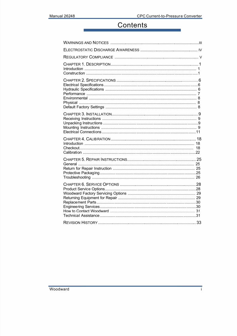
Contents
W ARNINGS AND NOTICES ............................................................................III
ELECTROSTATIC DISCHARGE AWARENESS ................................................. IV
REGULATORY COMPLIANCE ........................................................................V
CHAPTER 1. DESCRIPTION ........................................................................... 1
Introduction ............................................................................................................. 1
Construction ........................................................................................................... 1
CHAPTER 2. SPECIFICATIONS ...................................................................... 6
Electrical Specifications .......................................................................................... 6
Hydraulic Specifications ......................................................................................... 6
Performance ........................................................................................................... 7
Environmental ......................................................................................................... 8
Physical .................................................................................................................. 8
Default Factory Settings ......................................................................................... 8
CHAPTER 3. INSTALLATION.......................................................................... 9
Receiving Instructions ............................................................................................ 9
Unpacking Instructions ........................................................................................... 9
Mounting Instructions ............................................................................................. 9
Electrical Connections .......................................................................................... 11
CHAPTER 4. C ALIBRATION ......................................................................... 18
Introduction ........................................................................................................... 18
Checkout............................................................................................................... 18
Calibration ............................................................................................................ 22
CHAPTER 5. REPAIR INSTRUCTIONS........................................................... 25
General ................................................................................................................. 25
Return for Repair Instruction ................................................................................ 25
Protective Packaging ............................................................................................ 25
Troubleshooting .................................................................................................... 26
CHAPTER 6. SERVICE OPTIONS ................................................................. 28
Product Service Options ....................................................................................... 28
Woodward Factory Servicing Options .................................................................. 29
Returning Equipment for Repair ........................................................................... 29
Replacement Parts ............................................................................................... 30
Engineering Services ............................................................................................ 30
How to Contact Woodward ................................................................................... 31
Technical Assistance ............................................................................................ 31
REVISION HISTORY .................................................................................... 33
8/10/2019 9907-802 Woodward
http://slidepdf.com/reader/full/9907-802-woodward 4/42
CPC Current-to-Pressure Converter Manual 26248
ii Woodward
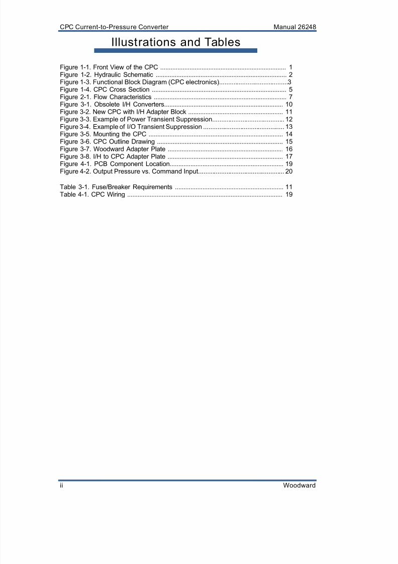
Illustrations and Tables
Figure 1-1. Front View of the CPC .........................................................................1
Figure 1-2. Hydraulic Schematic ............................................................................2
Figure 1-3. Functional Block Diagram (CPC electronics) ....................................... 3
Figure 1-4. CPC Cross Section ..............................................................................5
Figure 2-1. Flow Characteristics .............................................................................7 Figure 3-1. Obsolete I/H Converters.....................................................................10
Figure 3-2. New CPC with I/H Adapter Block .......................................................11
Figure 3-3. Example of Power Transient Suppression .........................................12
Figure 3-4. Example of I/O Transient Suppression ..............................................13
Figure 3-5. Mounting the CPC ..............................................................................14
Figure 3-6. CPC Outline Drawing .........................................................................15
Figure 3-7. Woodward Adapter Plate ...................................................................16
Figure 3-8. I/H to CPC Adapter Plate ...................................................................17
Figure 4-1. PCB Component Location..................................................................19
Figure 4-2. Output Pressure vs. Command Input .................................................20
Table 3-1. Fuse/Breaker Requirements ...............................................................11
Table 4-1. CPC Wiring ..........................................................................................19

8/10/2019 9907-802 Woodward
http://slidepdf.com/reader/full/9907-802-woodward 5/42

8/10/2019 9907-802 Woodward
http://slidepdf.com/reader/full/9907-802-woodward 6/42
CPC Current-to-Pressure Converter Manual 26248
iv Woodward
Battery ChargingDevice
To prevent damage to a control system that uses an alternator orbattery-charging device, make sure the charging device is turned offbefore disconnecting the battery from the system.
Electrostatic Discharge Awareness
ElectrostaticPrecautions
Electronic control s contain s tatic-sensitive parts. Observe thefollowing precautions to prevent damage to these parts:
Discharge body static before handling the contro l (with power tothe control turned off, contact a grounded surface and maintaincontact while handling the control).
Avoid al l plastic, vinyl, and Styrofoam (except antistatic vers ions)
around printed circuit boards. Do not touch the components or conductors on a printed circuit
board with your hands or with conductive devices.
To prevent damage to electronic components caused by improperhandling, read and observe the precautions in Woodward manual
82715, Guide for Handling and Protection of Electronic Contro ls,Printed Circuit Boards, and Modules.
Follow these precautions when working with or near the control.1. Avoid the build-up of static electricity on your body by not wearing clothing
made of synthetic materials. Wear cotton or cotton-blend materials as muchas possible because these do not store static electric charges as much as
synthetics.2. Do not remove the printed circuit board (PCB) from the control cabinet
unless absolutely necessary. If you must remove the PCB from the controlcabinet, follow these precautions:
Do not touch any part of the PCB except the edges.
Do not touch the electrical conductors, the connectors, or thecomponents with conductive devices or with your hands.
When replacing a PCB, keep the new PCB in the plastic antistaticprotective bag it comes in until you are ready to install it. Immediatelyafter removing the old PCB from the control cabinet, place it in theantistatic protective bag.
8/10/2019 9907-802 Woodward
http://slidepdf.com/reader/full/9907-802-woodward 7/42
Manual 26248 CPC Current-to-Pressure Converter
Woodward v
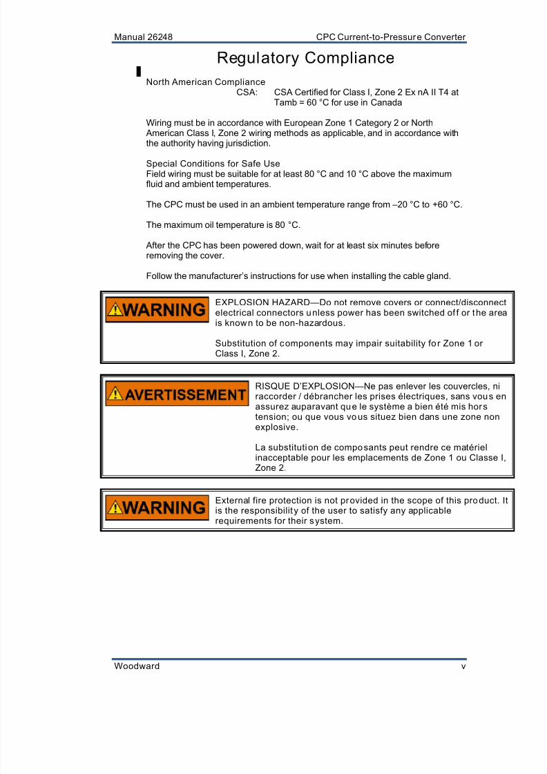
Regulatory Compliance
North American ComplianceCSA: CSA Certified for Class I, Zone 2 Ex nA II T4 at
Tamb = 60 °C for use in Canada
Wiring must be in accordance with European Zone 1 Category 2 or North
American Class I, Zone 2 wiring methods as applicable, and in accordance withthe authority having jurisdiction.
Special Conditions for Safe UseField wiring must be suitable for at least 80 °C and 10 °C above the maximumfluid and ambient temperatures.
The CPC must be used in an ambient temperature range from –20 °C to +60 °C.
The maximum oil temperature is 80 °C.
After the CPC has been powered down, wait for at least six minutes beforeremoving the cover.
Follow the manufacturer’s instructions for use when installing the cable gland.
EXPLOSION HAZARD—Do not remove covers or connect/disconnectelectrical connectors unless power has been switched of f or the areais known to be non-hazardous.
Substitution of components may impair suitability fo r Zone 1 orClass I, Zone 2.
RISQUE D’EXPLOSION—Ne pas enlever les couvercles, niraccorder / débrancher les prises électriques, sans vous en
assurez auparavant que le système a bien été mis horstension; ou que vous vous situez bien dans une zone nonexplosive.
La substituti on de composants peut rendre ce matérielinacceptable pour les emplacements de Zone 1 ou Classe I,Zone 2.
External fire protection is not provided in the scope of this product. Itis the responsibilit y of the user to satisfy any applicablerequirements for their system.

8/10/2019 9907-802 Woodward
http://slidepdf.com/reader/full/9907-802-woodward 8/42
CPC Current-to-Pressure Converter Manual 26248
vi Woodward
8/10/2019 9907-802 Woodward
http://slidepdf.com/reader/full/9907-802-woodward 9/42
Manual 26248 CPC Current-to-Pressure Converter
Woodward 1
Chapter 1.Description
Introduction
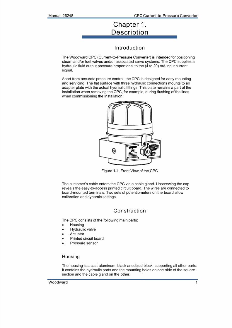
The Woodward CPC (Current-to-Pressure Converter) is intended for positioningsteam and/or fuel valves and/or associated servo systems. The CPC supplies ahydraulic fluid output pressure proportional to the (4 to 20) mA input currentsignal.
Apart from accurate pressure control, the CPC is designed for easy mountingand servicing. The flat surface with three hydraulic connections mounts to anadapter plate with the actual hydraulic fittings. This plate remains a part of theinstallation when removing the CPC, for example, during flushing of the lineswhen commissioning the installation.
Figure 1-1. Front View of the CPC
The customer’s cable enters the CPC via a cable gland. Unscrewing the capreveals the easy-to-access printed circuit board. The wires are connected toboard-mounted terminals. Two sets of potentiometers on the board allowcalibration and dynamic settings.
Construction
The CPC consists of the following main parts:
Housing
Hydraulic valve Actuator
Printed circuit board
Pressure sensor
Housing
The housing is a cast-aluminum, black anodized block, supporting all other parts.It contains the hydraulic ports and the mounting holes on one side of the squaresection and the cable gland on the other.

8/10/2019 9907-802 Woodward
http://slidepdf.com/reader/full/9907-802-woodward 10/42
CPC Current-to-Pressure Converter Manual 26248
2 Woodward
Figure 1-2. Hydraulic Schematic
Together with the aluminum cover, the flameproof enclosure contains theelectronics, the actuator, and the pressure sensor.
The spiral return spring is installed on the base and protected by a cover.
The CPC is protected against water and dust ingress per IEC 60529, IP65.
Hydraulic Valve
An innovative hydraulic valve controls the oil flow from supply to output port, orfrom output to tank. (see Figure 1-2). The valve consists of a steel bushing inwhich a steel plunger moves. The special construction ensures proper, reliable,and contaminant-tolerant operation, using standard lube oil.
Actuator
The CPC uses a Woodward-developed, rotary limited angle torque (LAT)actuator. It is a type of stepping motor with steps of 90 degrees, operated using amini-stepping technique in one quadrant. The rotating angle is mechanicallylimited to ±22.5°. The rotor, with the permanent magnet, is directly coupled to thehydraulic valve. The current signal to the coils is generated by the driver circuit ofthe electronics.
8/10/2019 9907-802 Woodward
http://slidepdf.com/reader/full/9907-802-woodward 11/42
Manual 26248 CPC Current-to-Pressure Converter
Woodward 3
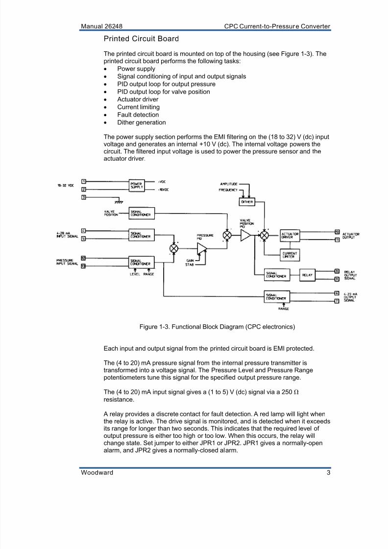
Printed Circuit Board
The printed circuit board is mounted on top of the housing (see Figure 1-3). Theprinted circuit board performs the following tasks:
Power supply
Signal conditioning of input and output signals
PID output loop for output pressure
PID output loop for valve position
Actuator driver
Current limiting
Fault detection
Dither generation
The power supply section performs the EMI filtering on the (18 to 32) V (dc) inputvoltage and generates an internal +10 V (dc). The internal voltage powers thecircuit. The filtered input voltage is used to power the pressure sensor and theactuator driver.
Figure 1-3. Functional Block Diagram (CPC electronics)
Each input and output signal from the printed circuit board is EMI protected.
The (4 to 20) mA pressure signal from the internal pressure transmitter istransformed into a voltage signal. The Pressure Level and Pressure Rangepotentiometers tune this signal for the specified output pressure range.
The (4 to 20) mA input signal gives a (1 to 5) V (dc) signal via a 250
resistance.
A relay provides a discrete contact for fault detection. A red lamp will light whenthe relay is active. The drive signal is monitored, and is detected when it exceedsits range for longer than two seconds. This indicates that the required level ofoutput pressure is either too high or too low. When this occurs, the relay willchange state. Set jumper to either JPR1 or JPR2. JPR1 gives a normally-openalarm, and JPR2 gives a normally-closed alarm.

8/10/2019 9907-802 Woodward
http://slidepdf.com/reader/full/9907-802-woodward 12/42
CPC Current-to-Pressure Converter Manual 26248
4 Woodward
The Signal Range potentiometer adjusts the current output signal so that theminimum and maximum pressures correspond with 4 mA and 20 mArespectively.
The actual valve position is measured by a non-contacting position sensor,integrated into the board.
The pressure output loop, with adjustable gain and stability, generates a valve
position reference signal for the valve position output loop, depending on thepressure reference signal and measured pressure signal. The dynamic settingscan be adjusted to match the characteristics of the controlled servo system.
The driver provides the actuator with a high-current, pulse-width-modulated(PWM) signal, depending on the drive demand signal.
The current passing through the actuator is monitored. It can go up to 5 A for aperiod of three seconds, boosting the torque of the actuator to its maximum.Then the current is limited to approximately 1.5 A, in order to protect the circuitry.
The drive demand signal checks that the CPC is functioning correctly. When thesignal exceeds its normal operating window for longer than two seconds, the
CPC is presumably unable to maintain the required pressure level, and the relaywill change state. A red lamp indicates when the alarm relay is active
A dither signal can be superimposed on the drive signal. The amplitude andfrequency can be adjusted. The dither signal is intended to give a relatively highfrequency ripple on the output pressure. It can be used to reduce the effect ofstatic friction in the CPC and the attached servo system.
Pressure Sensor
The pressure sensor is a two-wire (4 to 20) mA transmitter (with a third wire forshielding purposes).
When the CPC is supplied with hydraulic and electric power, and a current inputsignal between 4 mA and 20 mA, it will output a certain pressure within thefactory set pressure range. The operation is as follows. See also Figures 1-3 and1-4.
1. The pressure reference and actual pressure signals are compared by thepressure output loop, and generate a reference valve position signal.
2. The valve position is measured with a board-mounted sensor. The positionsignal, together with the valve position reference, is used by the positionoutput loop with fixed dynamics. This provides a fast and stable valveposition output.
3. The output loop outputs a drive signal. The driver generates the correct PWMhigh current signal to the actuator, which results in the valve position asrequired.
4. The hydraulic valve has two ports: Supply to Output and Output to Tank. Thethree hydraulic connections are indicated on the CPC.
5. With the hydraulic valve in its mid position, both ports are closed, andassuming no leakage is present, the output or output pressure is maintainedat its level.
8/10/2019 9907-802 Woodward
http://slidepdf.com/reader/full/9907-802-woodward 13/42
Manual 26248 CPC Current-to-Pressure Converter
Woodward 5
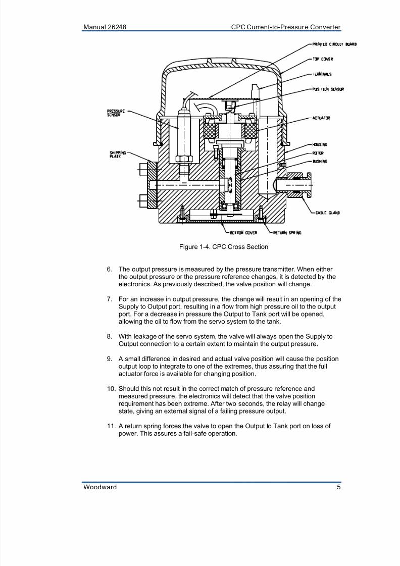
Figure 1-4. CPC Cross Section
6. The output pressure is measured by the pressure transmitter. When eitherthe output pressure or the pressure reference changes, it is detected by theelectronics. As previously described, the valve position will change.
7. For an increase in output pressure, the change will result in an opening of theSupply to Output port, resulting in a flow from high pressure oil to the outputport. For a decrease in pressure the Output to Tank port will be opened,allowing the oil to flow from the servo system to the tank.
8. With leakage of the servo system, the valve will always open the Supply toOutput connection to a certain extent to maintain the output pressure.
9. A small difference in desired and actual valve position will cause the positionoutput loop to integrate to one of the extremes, thus assuring that the fullactuator force is available for changing position.
10. Should this not result in the correct match of pressure reference and
measured pressure, the electronics will detect that the valve positionrequirement has been extreme. After two seconds, the relay will changestate, giving an external signal of a failing pressure output.
11. A return spring forces the valve to open the Output to Tank port on loss ofpower. This assures a fail-safe operation.

8/10/2019 9907-802 Woodward
http://slidepdf.com/reader/full/9907-802-woodward 14/42
CPC Current-to-Pressure Converter Manual 26248
6 Woodward
Chapter 2.Specifications
Electrical Specifications
Connections 9 terminals on the internal printed circuit boardsuitable for 0.5 mm² to 4 mm² solid or 0.5 mm²to 2.5 mm² stranded wire (22 AWG to 12 AWG)
Cable Entry via cable gland. Cable dia. 10.5 mm to 13 mmSupply Voltage (18 to 30) V (dc) / 24 V (dc) nominal (use cable
at least 1.5 mm²/16 AWG)Power Consumption 8 W during steady state, 48 W maximum, 65 W
peak transient (3 s maximum)Current Input Signal (4 to 20) mA into 250 . CMRR max. ±20 V (dc)
Analog Output Signal (4 to 20) mA. Maximum external load: 300
Accuracy ±1 % of full scaleDiscrete Output Signal Relay, jumper selectable for NO or NC, 100 000
operations
1.0 A at 30 V (dc), max. 33 V (dc)0.75 A inductive at 28 V (dc) 0.2 henry
Dither Frequency (10 to 30) Hz. Default setting is 30 HzDither Amplitude Zero is minimum and default. Maximum
depends on adjusted frequency and dynamiccharacteristics of the entire system.
The CPC must be powered by a power supply with a lim ited poweroutput according to NEC Class 02 (low voltage, low current).
Hydraulic SpecificationsConnections Flat mounting face with 3 holes. See Figure 3-6
for hydraulic connections, and Figures 3-7 or 3-8for mounting via an adapter plate (optional).
Supply Pressure 17 bar (250 psi) maximum. At least 0.5 barhigher than the maximum output pressure.
Tank Pressure At least 0.5 bar lower than the minimum outputpressure.
Output Pressure Min. level: 1 bar (14.5 psi), max. level: 15 bar(217.5 psi)Min. range: 1 bar (14.5 psi), max. range: 14 bar(203 psi)
Recommended External 40 µm nominal, 75 µm absolute or better (β40 =
Filter Rating 75 or better)(customer-installed)
Viscosity 20 cSt to 100 cStLeakage Depends on viscosity and supply pressure. See
Figure 2-1.Flow Capacity Depends on viscosity and pressure difference.
See Figure 2-1. Reverse flow is 30 % to 50 %greater than forward flow, due to the external(customer-supplied) filter near the supply input.
8/10/2019 9907-802 Woodward
http://slidepdf.com/reader/full/9907-802-woodward 15/42
Manual 26248 CPC Current-to-Pressure Converter
Woodward 7
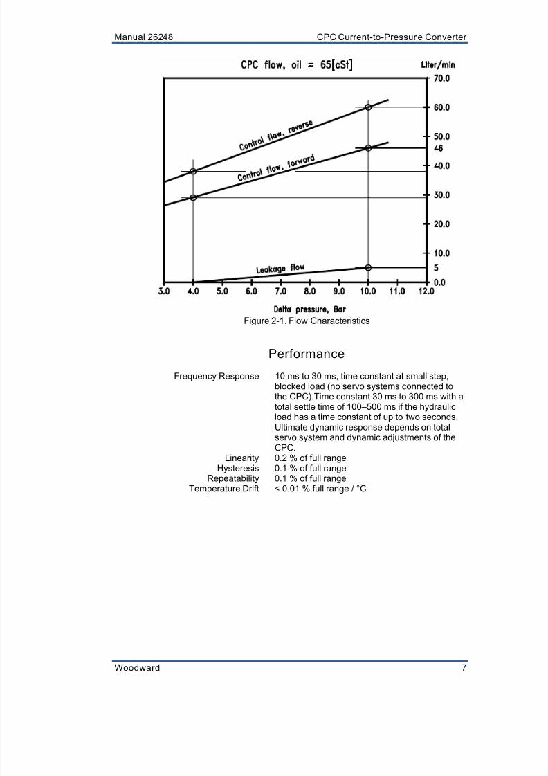
Figure 2-1. Flow Characteristics
Performance
Frequency Response 10 ms to 30 ms, time constant at small step,blocked load (no servo systems connected tothe CPC).Time constant 30 ms to 300 ms with a
total settle time of 100–500 ms if the hydraulicload has a time constant of up to two seconds.Ultimate dynamic response depends on totalservo system and dynamic adjustments of theCPC.
Linearity 0.2 % of full rangeHysteresis 0.1 % of full range
Repeatability 0.1 % of full rangeTemperature Drift < 0.01 % full range / °C

8/10/2019 9907-802 Woodward
http://slidepdf.com/reader/full/9907-802-woodward 16/42
CPC Current-to-Pressure Converter Manual 26248
8 Woodward
Environmental
Ambient Temperature (–20 to +60) °CHumidity 95 % relative humidity
Oil Temperature Continuously 60 °C max. Peak 80 °C (2–3 daysmaximum)
Max. Surface Temperature 85 °CVibration Lloyd’s LR type approval test spec. 1 and 2
(5 Hz to 100 Hz at 4G)
Ingress Protection IP65 per EN60529
Physical
See also Figure 3-6, CPC Outline Drawing.
Height x Width x Depth Approx. (220 x 170 x 170) mm / (8.7 x 6.7 x 6.7)inches
Weight Approx. 10 kg without oilMounting Four M10 threaded holes, (20 to 24) mm deep,
on the face with the hydraulic ports
Default Factory Settings
Gain = 30 % (1 turn potentiometer)Stability = 30 % (1 turn potentiometer)
Dither Amplitude = 0 % (1 turn potentiometer)Dither Frequency = 30 Hz (1 turn potentiometer)
Output Pressure Range = 1.5 bar to 4.5 bar (4 mA to 20 mA)

8/10/2019 9907-802 Woodward
http://slidepdf.com/reader/full/9907-802-woodward 17/42
Manual 26248 CPC Current-to-Pressure Converter
Woodward 9
Chapter 3.Installation
Receiving Instructions
The CPC is carefully packed at the factory to protect it from damage duringshipping; however, careless handling during shipment can result in damage. Ifany damage to the CPC is discovered, immediately notify both the shippingagent and Woodward. When unpacking the CPC, do not remove the hydraulicblanking plugs until you are ready to mount the unit.
Unpacking Instructions
Carefully unpack the CPC and remove it from the shipping container. Do notremove the shipping plate or plugs, until ready to mount.
External fire protection is not provided in the scope of this product. It
is the responsibilit y of the user to satisfy any applicablerequirements for their system.
Due to typical noise levels in turbine environments, hearingprotection should be worn when working on or around the CPC.
The surface of this product can become hot enough or cold enoughto be a hazard. Use protective gear for product handling in thesecircumstances. Temperature ratings are included in the specificationsection of th is manual.
Mounting Instructions
Location Considerations
When selecting a location for the CPC, consider the following:
Provide adequate ventilation and avoid placing or attaching the CPC to heatgenerating or conducting parts of the installation.
Locate the CPC as close as possible to the servo: short hydraulic lines (andvolume) help to achieve optimum response.
Avoid mounting the CPC at places with excessive vibration.
Mounting the CPC(Figure 3-5)
The CPC is designed for vertical or horizontal mounting.
The CPC mounts to an adapter block (or plate). The adapter block connects thethree hydraulic CPC ports with the external oil supply, turbine drain, and control-output of the steam valve servo. The CPC is attached (clamped) to the adapterblock by M10 screws. The screws should screw into the CPC a minimum of20 mm for a reliable and solid mounting.
8/10/2019 9907-802 Woodward
http://slidepdf.com/reader/full/9907-802-woodward 18/42

8/10/2019 9907-802 Woodward
http://slidepdf.com/reader/full/9907-802-woodward 19/42
8/10/2019 9907-802 Woodward
http://slidepdf.com/reader/full/9907-802-woodward 20/42
CPC Current-to-Pressure Converter Manual 26248
12 Woodward
Transient Suppression
Protecting electrical loads and sensitive digital equipment from hazardous powerdisturbances is critical. Protection is required if the transients may exist, if I/Ocabling is long (>30 m), or when the power cable is not connected to local ordistributed power, and is not relatively short (<10 m).
Transient voltage on the input power lines can be caused by external events
such as lightning, or from power factor corrections and grid switching on theutility network. The transients can also be caused internally by turning on and offlarge inductive loads with long cable length. Transient voltage suppression(TVS or MOV devices) must be installed to avoid these problems.
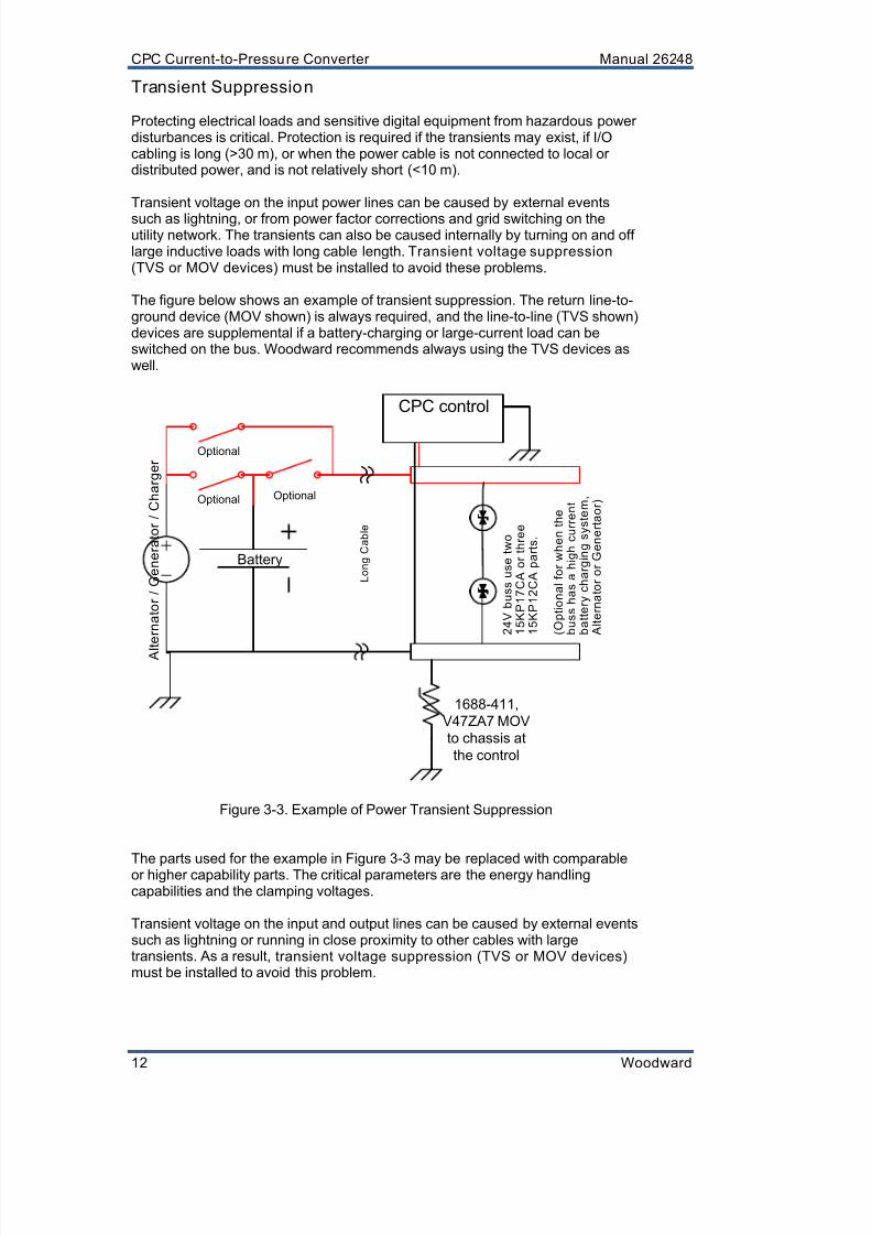
The figure below shows an example of transient suppression. The return line-to-ground device (MOV shown) is always required, and the line-to-line (TVS shown)devices are supplemental if a battery-charging or large-current load can beswitched on the bus. Woodward recommends always using the TVS devices aswell.
Optional
Battery
A l t e r n a t o r / G e n e r a t o r / C h a r g e r
Optional
L o n g C a b l e
CPC control
Optional
1688-411,
V47ZA7 MOV
to chassis at
the control
2 4 V
b u s s u s e t w o
1 5 K P 1 7 C A
o r t h r e e
1 5 K P 1 2 C A
p a r t s .
( O p t i o n a l f o r w h e n t h e
b u s s h a s a h i g h c u r r e n t
b a t t e r y c h a r g i n g s y s t e m ,
A l t e r n a t o r o r G e n e r t a o r )
Figure 3-3. Example of Power Transient Suppression
The parts used for the example in Figure 3-3 may be replaced with comparableor higher capability parts. The critical parameters are the energy handlingcapabilities and the clamping voltages.
Transient voltage on the input and output lines can be caused by external eventssuch as lightning or running in close proximity to other cables with largetransients. As a result, transient voltage suppression (TVS or MOV devices) must be installed to avoid this problem.
8/10/2019 9907-802 Woodward
http://slidepdf.com/reader/full/9907-802-woodward 21/42
Manual 26248 CPC Current-to-Pressure Converter
Woodward 13
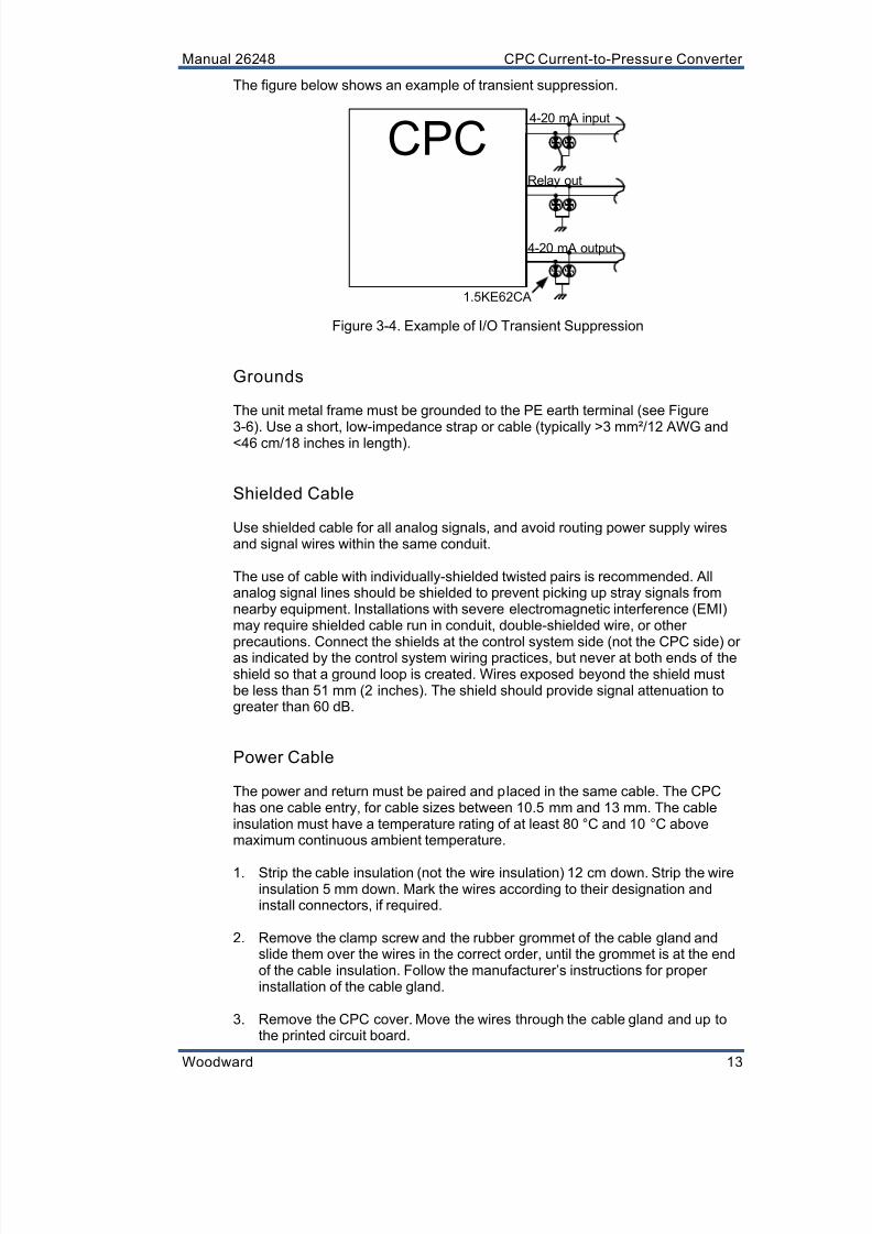
The figure below shows an example of transient suppression.
CPC4-20 mA input
4-20 mA output
Relay out
1.5KE62CA
Figure 3-4. Example of I/O Transient Suppression
Grounds
The unit metal frame must be grounded to the PE earth terminal (see Figure
3-6). Use a short, low-impedance strap or cable (typically >3 mm²/12 AWG and<46 cm/18 inches in length).
Shielded Cable
Use shielded cable for all analog signals, and avoid routing power supply wiresand signal wires within the same conduit.
The use of cable with individually-shielded twisted pairs is recommended. Allanalog signal lines should be shielded to prevent picking up stray signals fromnearby equipment. Installations with severe electromagnetic interference (EMI)may require shielded cable run in conduit, double-shielded wire, or other
precautions. Connect the shields at the control system side (not the CPC side) oras indicated by the control system wiring practices, but never at both ends of theshield so that a ground loop is created. Wires exposed beyond the shield mustbe less than 51 mm (2 inches). The shield should provide signal attenuation togreater than 60 dB.
Power Cable
The power and return must be paired and placed in the same cable. The CPChas one cable entry, for cable sizes between 10.5 mm and 13 mm. The cableinsulation must have a temperature rating of at least 80 °C and 10 °C abovemaximum continuous ambient temperature.
1. Strip the cable insulation (not the wire insulation) 12 cm down. Strip the wireinsulation 5 mm down. Mark the wires according to their designation andinstall connectors, if required.
2. Remove the clamp screw and the rubber grommet of the cable gland andslide them over the wires in the correct order, until the grommet is at the endof the cable insulation. Follow the manufacturer’s instructions for properinstallation of the cable gland.
3. Remove the CPC cover. Move the wires through the cable gland and up tothe printed circuit board.

8/10/2019 9907-802 Woodward
http://slidepdf.com/reader/full/9907-802-woodward 22/42
CPC Current-to-Pressure Converter Manual 26248
14 Woodward
4. Re-install and tighten the clamp screw. The Teflon tubing provided with theCPC can be used to protect the wires inside the CPC.
5. Connect the wires to the terminals on the printed circuit board. The terminalsaccept wires as specified in the Electrical Specifications in Chapter 2. Aminimum wire size of 1 mm² or 18 AWG is recommended for signals. Aminimum wire size of 1.5 mm² is recommended for power. The terminaldesignations are shown in Table 4-1. Terminals 10 to 13 are pre-wired at the
Woodward factory and should not be changed.
6. Secure the cable outside the CPC to prevent pull forces on the cable gland.
Figure 3-5. Mounting the CPC
SUPPLY
OUTPUT
TANK
Torque rating forlocking block screw:Torque the screw to2.5 N
m (1.8 lb-ft).

8/10/2019 9907-802 Woodward
http://slidepdf.com/reader/full/9907-802-woodward 23/42
Manual 26248 CPC Current-to-Pressure Converter
Woodward 15
Figure 3-6. CPC Outline Drawing
8/10/2019 9907-802 Woodward
http://slidepdf.com/reader/full/9907-802-woodward 24/42
CPC Current-to-Pressure Converter Manual 26248
16 Woodward
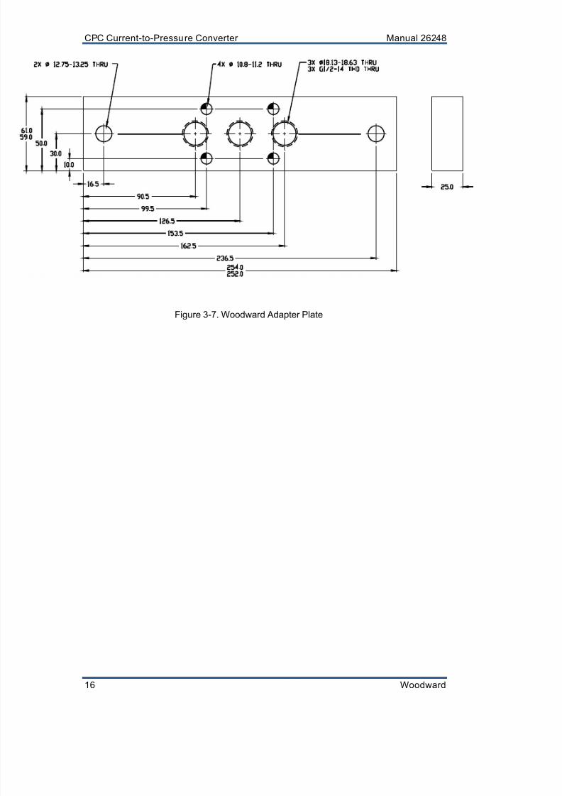
Figure 3-7. Woodward Adapter Plate

8/10/2019 9907-802 Woodward
http://slidepdf.com/reader/full/9907-802-woodward 25/42
Manual 26248 CPC Current-to-Pressure Converter
Woodward 17
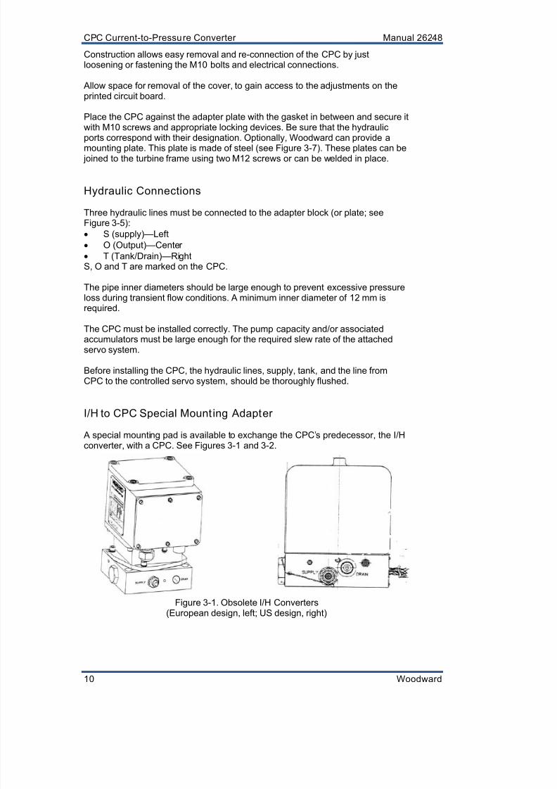
The Woodward I/H converter is obsolete. It can easily be replaced bythe CPC using Woodward adapter p late 3689-097.
Figure 3-8. I/H to CPC Adapter Plate
4 X
°
1 0 . 5 - 1 1 . 5
T H R U
4 X
=
°
2 0 . 6 - 2 1 . 4
?
1 2 . 2 - 1 3 . 2
4 X
°
1 0 . 5 - 1 1 . 5
T H R U
4 X
=
°
2 0 . 6 - 2 1 . 4
?
1 2
. 2 - 1 3 . 2
F R O M
O T H E R
S I D E
3 X
°
1 0 . 5 - 1 1 . 5
. 7 5 0 - 1 6
U N J F - 2 B
T H D
S T R A I G H T
T H R E A D
P O R T
P E R
S S - 1 4 5
S
T
2 X
. 7 5 0 - 1 6
U N J F - 2 B
T H D
S T R A I G H T T
H R E A D
P O R T
P E R
S S - 1 4 5
2 5 .
4
3 9 .
9
9 8 .
6
5 4 . 0
2 5 .
4
8 6 .
5
4 6 . 2
1 6 7 . 9
1 5 3 . 8
8 3 . 9
5
3 6 . 0
2 7 . 0
2 7 . 0
3 6 . 0
1 4 . 1
2 0 . 6 5
2 0 . 6 5
1 1 7 .
0
1 5 3 .
8
1 6 7 . 9
1 4 .
1
8
5 . 9
8/10/2019 9907-802 Woodward
http://slidepdf.com/reader/full/9907-802-woodward 26/42
CPC Current-to-Pressure Converter Manual 26248
18 Woodward
Chapter 4.Calibration
Introduction
After installation, the CPC must be checked for proper operation and calibrationbefore use. The factory has conducted a functional test. Final checkout andcustomer calibration must be completed after installation. For default factorysettings, see Chapter 2.
The engine, turbine, or other type of prime mover should beequipped with an overspeed shutdown device to protect againstrunaway or damage to the prime mover with possible personal injury,loss o f life, or property damage.
The overspeed shutdown device must be totally independent of theprime mover contro l system. An overtemperature or overpressureshutdown device may also be needed for safety, as appropr iate.
EXPLOSION HAZARD—In the case of an explosion hazardousenvironment, ensure that the area is non-hazardous prior to openingthe flameproof compartment. After the CPC has been powered down,wait for at least six minutes before removing the cover.
Checkout
A checkout of the CPC is done to verify proper installation, wiring, andconnection of the hydraulic lines.
The checkout procedure will verify correct installation. Thisprocedure is a bench test o f the CPC.
The checkout procedure cannot be run, if the prime mover ispowered up.
8/10/2019 9907-802 Woodward
http://slidepdf.com/reader/full/9907-802-woodward 27/42
Manual 26248 CPC Current-to-Pressure Converter
Woodward 19
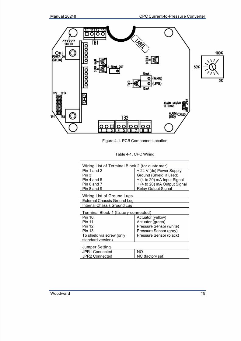
Figure 4-1. PCB Component Location
Table 4-1. CPC Wiring
Wiring List of Terminal Block 2 (for customer)
Pin 1 and 2 + 24 V (dc) Power SupplyPin 3 Ground (Shield, if used)
Pin 4 and 5 + (4 to 20) mA Input SignalPin 6 and 7 + (4 to 20) mA Output SignalPin 8 and 9 Relay Output Signal
Wiring List of Ground Lugs
External Chassis Ground Lug
Internal Chassis Ground Lug
Terminal Block 1 (factory connected)
Pin 10 Actuator (yellow)Pin 11 Actuator (green)Pin 12 Pressure Sensor (white)Pin 13 Pressure Sensor (gray)To shield via screw (only
standard version)
Pressure Sensor (black)
Jumper Setting
JPR1 Connected NOJPR2 Connected NC (factory set)
8/10/2019 9907-802 Woodward
http://slidepdf.com/reader/full/9907-802-woodward 28/42
CPC Current-to-Pressure Converter Manual 26248
20 Woodward
Explanation of Adjus tments and Test Points
Seven adjustments can be made, and 14 test points have been provided. Theadjustments are explained below. See Figure 4-1 for the location of thepotentiometers and test points (TPs). For default factory settings, see Chapter 2.
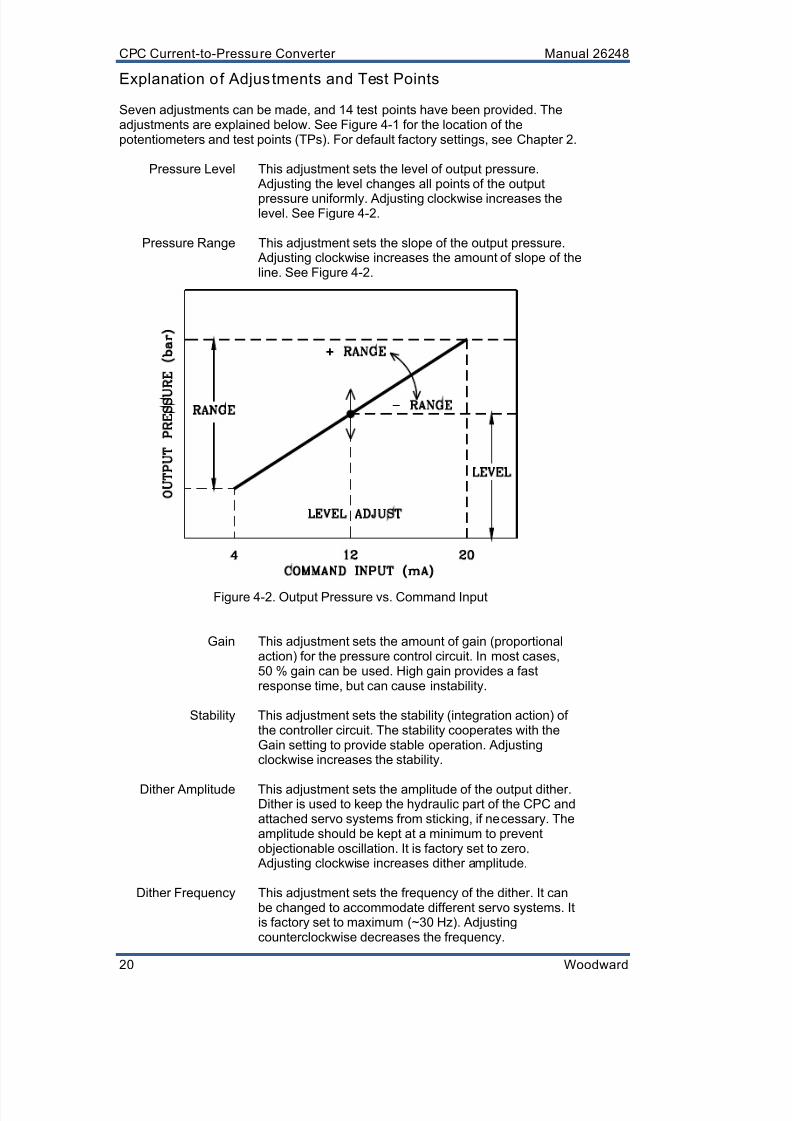
Pressure Level This adjustment sets the level of output pressure. Adjusting the level changes all points of the output
pressure uniformly. Adjusting clockwise increases thelevel. See Figure 4-2.
Pressure Range This adjustment sets the slope of the output pressure. Adjusting clockwise increases the amount of slope of theline. See Figure 4-2.
Figure 4-2. Output Pressure vs. Command Input
Gain This adjustment sets the amount of gain (proportionalaction) for the pressure control circuit. In most cases,50 % gain can be used. High gain provides a fastresponse time, but can cause instability.
Stability This adjustment sets the stability (integration action) ofthe controller circuit. The stability cooperates with theGain setting to provide stable operation. Adjustingclockwise increases the stability.
Dither Amplitude This adjustment sets the amplitude of the output dither.Dither is used to keep the hydraulic part of the CPC andattached servo systems from sticking, if necessary. Theamplitude should be kept at a minimum to preventobjectionable oscillation. It is factory set to zero.
Adjusting clockwise increases dither amplitude.
Dither Frequency This adjustment sets the frequency of the dither. It canbe changed to accommodate different servo systems. Itis factory set to maximum (~30 Hz). Adjustingcounterclockwise decreases the frequency.
8/10/2019 9907-802 Woodward
http://slidepdf.com/reader/full/9907-802-woodward 29/42
Manual 26248 CPC Current-to-Pressure Converter
Woodward 21
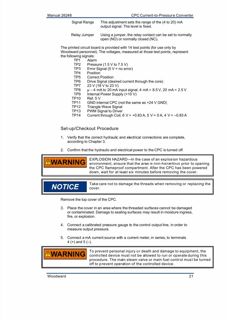
Signal Range This adjustment sets the range of the (4 to 20) mAoutput signal. The level is fixed.
Relay Jumper Using a jumper, the relay contact can be set to normallyopen (NO) or normally closed (NC).
The printed circuit board is provided with 14 test points (for use only byWoodward personnel). The voltages, measured at those test points, represent
the following signals:TP1 AlarmTP2 Pressure (1.5 V to 7.5 V)TP3 Error Signal (5 V = no error)TP4 PositionTP5 Correct PositionTP6 Drive Signal (desired current through the core)TP7 23 V (18 V to 23 V)TP8 µ – 4 mA to 20 mA input signal, 4 mA = 8.5 V, 20 mA = 2.5 VTP9 Internal Power Supply (+10 V)
TP10 Ref. 5 VTP11 GND internal CPC (not the same as +24 V GND)TP12 Triangle Wave Signal
TP13 PWM Signal to DriverTP14 Current through Coil, 6 V = +0.83 A, 5 V = 0 A, 4 V = –0.83 A
Set-up/Checkout Procedure
1. Verify that the correct hydraulic and electrical connections are complete,according to Chapter 3.
2. Confirm that the hydraulic and electrical power to the CPC is turned off.
EXPLOSION HAZARD—In the case of an exp losion hazardousenvironment, ensure that the area is non-hazardous prior to opening
the CPC flameproof compartment. After the CPC has been powereddown, wait for at least six minutes before removing the cover.
Take care not to damage the threads when removing or replacing thecover.
Remove the top cover of the CPC.
3. Place the cover in an area where the threaded surfaces cannot be damagedor contaminated. Damage to sealing surfaces may result in moisture ingress,fire, or explosion.
4. Connect a calibrated pressure gauge to the control output line, in order tomeasure output pressure.
5. Connect a mA current source with a current meter, in series, to terminals4 (+) and 5 (–).
To prevent personal injury o r death and damage to equipment, thecontro lled device must not be allowed to run or operate during thisprocedure. The main steam valve or main fuel control must be turnedoff to prevent operation of the controlled device.

8/10/2019 9907-802 Woodward
http://slidepdf.com/reader/full/9907-802-woodward 30/42
CPC Current-to-Pressure Converter Manual 26248
22 Woodward
6. Apply electrical power to the CPC. The green LED will illuminate.
7. Check the power supply by measuring the voltage at terminal 1 and 2.
8. Check internal power supply at test pins TP9 and TP11. The reading shouldbe (+10 ± 0.1) V (dc).
9. Start the hydraulic supply system and turn the current source on. Check that
the oil is up to operating temperature and that all air has been purged fromthe system. The air can be purged by adjusting the current input signal upand down several times. Allow for warm-up time.
10. Observe the pressure gauge when changing the current input signal. Thepressure level should correspond with the default values specified in Chapter 2.
Calibration
This section covers calibration and other electrical adjustments of the CPC. Referto Figure 4-1 for the location of the different potentiometers.
Output Pressure vs. Command Input
1. Set the current source to 12 mA and measure the output pressure.
2. Adjust the Pressure Level for the desired output pressure.
3. Adjust the current source to 20 mA and measure the output pressure.
4. Adjust the Pressure Range for the desired output pressure.
5. Check the 12 mA setting again, and adjust the level if necessary.
6. Check the 4 mA setting again, and adjust the output with range if necessary.Note that turning the range clockwise results in a decrease of pressure.
7. Repeat steps 1 through 6 until the output pressures at both extremes fall inthe desired tolerance.
The pressure level and pressure range adjustments are 25-turnpotentiometers.
Dynamic Adjustments
1. Adjust the current source to 12 mA.
2. Adjust the Gain slowly clockwise to the middle position. If the controlledoutput pressure becomes unstable, adjust the Gain counterclockwise.Normally 50 % gain can be used for all types of loads.
3. Turn the Gain counterclockwise for small servo volumes, and clockwise forbigger servo volumes.

8/10/2019 9907-802 Woodward
http://slidepdf.com/reader/full/9907-802-woodward 31/42
Manual 26248 CPC Current-to-Pressure Converter
Woodward 23
4. Use 10 % to 20 % stability for a small or blocked servo. Use 50 % to 60 % fora bigger servo, with about two seconds time constant. Increase the stabilityfurther if the oil is cold or has a high viscosity.
5. If high frequency oscillations are observed, the Stability can be decreased.Decreasing the Stability normally results in the possibility to further increasethe Gain.
6. Check the stability over the full range by adjusting the input current between4 mA and 20 mA in small stepwise changes.
Output Current Signal
This signal is factory calibrated. If needed, re-adjust as follows:
1. Connect a current meter to terminals 6 (+) and 7 (–). Set the input currentsource to 12 mA and measure the output current signal.
2. Adjust the Signal Range until the output signal is 12 mA.
3. Adjust the current source to 4 mA and 20 mA and measure the output currentsignal.
4. Adjust the Signal Range until both the 4 mA and 20 mA fall within ±1 %accuracy.
The level is fixed to 0 mA.
Discrete Output Signal
The jumper setting for a NO or NC contact is shown in Figure 4-1. When an errorcondition is present, such as incorrect pressure or incorrect position at the
internal valve, the relay will switch and the red lamp will illuminate. This majoralarm has a set and reset time of two seconds. A non-resettable function of therelay can be achieved by adding an external relay circuit.
Dither
The dither can be adjusted while the prime mover is operating. Beware ofunacceptable oscillations when introducing dither. It is recommended to alwaysuse some dither.
1. Turn the Dither Amplitude clockwise to increase the amplitude until oscillationof the output pressure or valve position can be observed. Decrease the
amplitude slightly to prevent objectionable wear in the system.
2. If the frequency is too high for the attached servo system, reduce it by turningthe Dither Frequency counterclockwise.
Due to the dynamic characteristics of the CPC, the amplitude of the pressurefluctuations will normally increase when reducing the frequency.
8/10/2019 9907-802 Woodward
http://slidepdf.com/reader/full/9907-802-woodward 32/42
CPC Current-to-Pressure Converter Manual 26248
24 Woodward
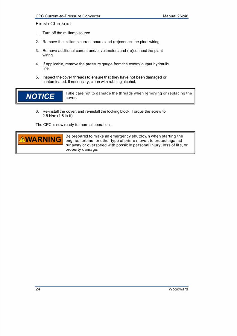
Finish Checkout
1. Turn off the milliamp source.
2. Remove the milliamp current source and (re)connect the plant wiring.
3. Remove additional current and/or voltmeters and (re)connect the plantwiring.
4. If applicable, remove the pressure gauge from the control output hydraulicline.
5. Inspect the cover threads to ensure that they have not been damaged orcontaminated. If necessary, clean with rubbing alcohol.
Take care not to damage the threads when removing or replacing thecover.
6. Re-install the cover, and re-install the locking block. Torque the screw to
2.5 N
m (1.8 lb-ft).
The CPC is now ready for normal operation.
Be prepared to make an emergency shutdown when starting theengine, turbine, or other type of prime mover, to protect againstrunaway or overspeed with possib le personal injury, loss of lif e, orproperty damage.

8/10/2019 9907-802 Woodward
http://slidepdf.com/reader/full/9907-802-woodward 33/42
Manual 26248 CPC Current-to-Pressure Converter
Woodward 25
Chapter 5.Repair Instructions
General
EXPLOSION HAZARD—In the case of an exp losion hazardousenvironment, ensure that the area is non-hazardous prior to openingthe CPC flameproof compartment. After the CPC has been powereddown, wait for at least six minutes before removing the cover.
Repairs and servicing of the CPC must be performed by Woodward or itsauthorized service facilities.
Replacement of the cable gland by an uncertified (not EEx-d) cable gland or withanother thread size will invalidate the suitability for hazardous locations.
Removal or vandalism of the nameplate is prohibited.
Return for Repair Instruction
Should the CPC need to be returned for repair, attach a tag on the unit. Includethe following information on the tag:
Customer's name and address
The name and location where the equipment is installed
Complete Woodward part number and serial number
Description of the failure
Instructions as to what type of repair is to be done
Protective Packaging
The following procedures are used for protective packaging of the CPC, ifreturning for repair:1. Install shipping plates or plugs in all hydraulic connection ports or seal with
tape.2. Wrap the CPC with packaging materials that will not damage the surface of
the unit.3. Place in a double-walled packing carton.4. Place at least 10 cm of tightly packed, industry-approved, shock-absorbing
material around the unit.5. Secure the carton with strong tape around the outside of the carton to
increase the strength of the carton.

8/10/2019 9907-802 Woodward
http://slidepdf.com/reader/full/9907-802-woodward 34/42
CPC Current-to-Pressure Converter Manual 26248
26 Woodward
Troubleshooting
General
The following troubleshooting guide will help you isolate trouble with the controlcircuit board, actuator, wiring, or elsewhere. Troubleshooting beyond this level isrecommended ONLY when a complete facility for control testing is available.
The wrong voltage can damage the control. When replacing a control, check thepower source and wiring connections for the correct voltage.
Troubleshooting Procedure
This table is a general guide for isolating system problems. Before using theguide, make sure that the system wiring contacts and input/output connectionsare correct and in good working order. Complete the checks in order. Each checkassumes that the preceding checks have been completed and any problemshave been corrected.
Be prepared to make an emergency shutdown when starting theengine, turbine, or other type of prime mover, to protect againstrunaway or overspeed with possib le personal injury, loss of lif e, orproperty damage.
Problem Cause Remedy
No pressure out. Faulty power, check green lamp. Check power connections, 24 V (dc) atpins 1 and 2 (pin 1 should be +).
Error condition, check red lamp(= alarm = discrete output isactive).
If on: Check actuator wire connection.
If off: Check pressure sensorwires.
Power supply too weak. Change power supply. Seespecification.
Power supply is limiting current. Change limit level to maximum(>= 5 A).
Bad power supply. Use Woodward recommended powersupply.
Full pressure out. Pressure sensor connectedincorrectly.
Check wire connections (Table 4-1).
Other faulty wiring. Check wire connections (Table 4-1).
Slow dynamics. Dynamic adjustments notoptimal.
Raise Stability, and maybe Gain.
Cold oil (viscosity too high). Wait until normal temperature isreached or change dynamicadjustments (raise Stability).
Tubes too small or too long. Use bigger and/or shorter tubes.
Water in oil. Clean or change the oil.
High-frequencyoscillation. Servo is outside its workingrange. Nothing—this is normal.
Oil viscosity changed. Re-adjust dynamics or reduce dither.
Faulty valve position feedback. Contact Woodward service.
Low-frequencyoscillation.
High friction in servo. Change dither amplitude andfrequency.
Abnormal high friction in servo. Clean or change servo piston. Low CPC internal friction. Change dither amplitude and
frequency. High CPC internal friction. Contact Woodward service.
8/10/2019 9907-802 Woodward
http://slidepdf.com/reader/full/9907-802-woodward 35/42
Manual 26248 CPC Current-to-Pressure Converter
Woodward 27
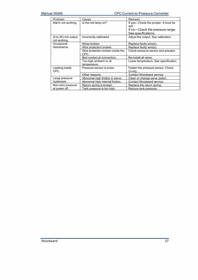
Problem Cause Remedy
Alarm not working. Is the red lamp on? If yes—Check the jumper. It must beset!
If no—Check the pressure range.See specifications.
(4 to 20) mA outputnot working.
Incorrectly calibrated. Adjust the output. See calibration.
Occasionaldisturbance.
Wires broken. Replace faulty wire(s).
Wire protection broken. Replace faulty wire(s).
Wire protection broken inside theCPC.
Check pressure sensor and actuator.
Bad contact at connectors. Re-install all wires.
Too high ambient or oiltemperature.
Lower temperature. See specification.
Leaking insideCPC.
Pressure sensor is loose. Fasten the pressure sensor. CheckO-ring.
Other reasons. Contact Woodward service.
Large pressurehysteresis.
Abnormal high friction in servo. Clean or change servo piston.
Abnormal high internal friction. Contact Woodward service.
Non-zero pressureat power off.
Return spring is broken. Replace the return spring.
Tank pressure is too high. Reduce tank pressure.

8/10/2019 9907-802 Woodward
http://slidepdf.com/reader/full/9907-802-woodward 36/42
CPC Current-to-Pressure Converter Manual 26248
28 Woodward
Chapter 6.Service Options
Product Service Options
If you are experiencing problems with the installation, or unsatisfactoryperformance of a Woodward product, the following options are available:
Consult the troubleshooting guide in the manual.
Contact the manufacturer or packager of your system.
Contact the Woodward Full Service Distributor serving your area.
Contact Woodward technical assistance (see “How to Contact Woodward”later in this chapter) and discuss your problem. In many cases, yourproblem can be resolved over the phone. If not, you can select which courseof action to pursue based on the available services listed in this chapter.
OEM and Packager Support : Many Woodward controls and control devices areinstalled into the equipment system and programmed by an Original EquipmentManufacturer (OEM) or Equipment Packager at their factory. In some cases, the
programming is password-protected by the OEM or packager, and they are the bestsource for product service and support. Warranty service for Woodward productsshipped with an equipment system should also be handled through the OEM orPackager. Please review your equipment system documentation for details.
Woodward Business Partner Support : Woodward works with and supports aglobal network of independent business partners whose mission is to serve theusers of Woodward controls, as described here:
A Full Service Distributor has the primary responsibility for sales, service,system integration solutions, technical desk support, and aftermarketmarketing of standard Woodward products within a specific geographic areaand market segment.
An Author ized Independent Service Facil ity (AISF) provides authorizedservice that includes repairs, repair parts, and warranty service on Woodward'sbehalf. Service (not new unit sales) is an AISF's primary mission.
A Recognized Engine Retrof itter (RER) is an independent company thatdoes retrofits and upgrades on reciprocating gas engines and dual-fuelconversions, and can provide the full line of Woodward systems andcomponents for the retrofits and overhauls, emission compliance upgrades,long term service contracts, emergency repairs, etc.
A Recognized Turbine Retrofitter (RTR) is an independent company thatdoes both steam and gas turbine control retrofits and upgrades globally, andcan provide the full line of Woodward systems and components for theretrofits and overhauls, long term service contracts, emergency repairs, etc.
You can locate your nearest Woodward distributor, AISF, RER, or RTR on ourwebsite at:
www.woodward.com/directory

8/10/2019 9907-802 Woodward
http://slidepdf.com/reader/full/9907-802-woodward 37/42
Manual 26248 CPC Current-to-Pressure Converter
Woodward 29
Woodward Factory Servicing Options
The following factory options for servicing Woodward products are availablethrough your local Full-Service Distributor or the OEM or Packager of theequipment system, based on the standard Woodward Product and ServiceWarranty (5-01-1205) that is in effect at the time the product is originally shippedfrom Woodward or a service is performed:
Replacement/Exchange (24-hour service)
Flat Rate Repair
Flat Rate Remanufacture
Replacement/Exchange: Replacement/Exchange is a premium programdesigned for the user who is in need of immediate service. It allows you torequest and receive a like-new replacement unit in minimum time (usually within24 hours of the request), providing a suitable unit is available at the time of therequest, thereby minimizing costly downtime. This is a flat-rate program andincludes the full standard Woodward product warranty (Woodward Product andService Warranty 5-01-1205).
This option allows you to call your Full-Service Distributor in the event of anunexpected outage, or in advance of a scheduled outage, to request a
replacement control unit. If the unit is available at the time of the call, it canusually be shipped out within 24 hours. You replace your field control unit withthe like-new replacement and return the field unit to the Full-Service Distributor.
Charges for the Replacement/Exchange service are based on a flat rate plusshipping expenses. You are invoiced the flat rate replacement/exchange chargeplus a core charge at the time the replacement unit is shipped. If the core (fieldunit) is returned within 60 days, a credit for the core charge will be issued.
Flat Rate Repair: Flat Rate Repair is available for the majority of standardproducts in the field. This program offers you repair service for your products withthe advantage of knowing in advance what the cost will be. All repair work carriesthe standard Woodward service warranty (Woodward Product and Service
Warranty 5-01-1205) on replaced parts and labor.
Flat Rate Remanufacture: Flat Rate Remanufacture is very similar to the FlatRate Repair option with the exception that the unit will be returned to you in “like-new” condition and carry with it the full standard Woodward product warranty(Woodward Product and Service Warranty 5-01-1205). This option is applicableto mechanical products only.
Returning Equipment for Repair
If a control (or any part of an electronic control) is to be returned for repair,please contact your Full-Service Distributor in advance to obtain Return
Authorization and shipping instructions.
When shipping the item(s), attach a tag with the following information:
return authorization number;
name and location where the control is installed;
name and phone number of contact person;
complete Woodward part number(s) and serial number(s);
description of the problem;
instructions describing the desired type of repair.
8/10/2019 9907-802 Woodward
http://slidepdf.com/reader/full/9907-802-woodward 38/42
CPC Current-to-Pressure Converter Manual 26248
30 Woodward
Packing a Contro l
Use the following materials when returning a complete control:
protective caps on any connectors;
antistatic protective bags on all electronic modules;
packing materials that will not damage the surface of the unit;
at least 100 mm (4 inches) of tightly packed, industry-approved packingmaterial;
a packing carton with double walls;
a strong tape around the outside of the carton for increased strength.
To prevent damage to electronic components caused by improperhandling, read and observe the precautions in Woodward manual82715, Guide for Handling and Protection of Electronic Contro ls,Printed Circuit Boards, and Modules.
Replacement Parts
When ordering replacement parts for controls, include the following information: the part number(s) (XXXX-XXXX) that is on the enclosure nameplate;
the unit serial number, which is also on the nameplate.
Engineering Services
Woodward offers various Engineering Services for our products. For these services,you can contact us by telephone, by email, or through the Woodward website.
Technical Support
Product Training
Field Service
Technical Support is available from your equipment system supplier, your local Full-Service Distributor, or from many of Woodward’s worldwide locations, dependingupon the product and application. This service can assist you with technicalquestions or problem solving during the normal business hours of the Woodwardlocation you contact. Emergency assistance is also available during non-businesshours by phoning Woodward and stating the urgency of your problem.
Product Training is available as standard classes at many of our worldwidelocations. We also offer customized classes, which can be tailored to your needsand can be held at one of our locations or at your site. This training, conductedby experienced personnel, will assure that you will be able to maintain systemreliability and availability.
Field Service engineering on-site support is available, depending on the productand location, from many of our worldwide locations or from one of our Full-Service Distributors. The field engineers are experienced both on Woodwardproducts as well as on much of the non-Woodward equipment with which ourproducts interface.
For information on these services, please contact us via telephone, email us, oruse our website: www.woodward.com.

8/10/2019 9907-802 Woodward
http://slidepdf.com/reader/full/9907-802-woodward 39/42
Manual 26248 CPC Current-to-Pressure Converter
Woodward 31
How to Contact Woodward
For assistance, call one of the following Woodward facilities to obtain the addressand phone number of the facility nearest your location where you will be able toget information and service.
Electrical Power SystemsFacili ty ---------------- Phone NumberBrazil ------------- +55 (19) 3708 4800China ----------- +86 (512) 6762 6727Germany --------- +49 (0) 21 52 14 51India --------------- +91 (129) 4097100Japan -------------- +81 (43) 213-2191Korea -------------- +82 (51) 636-7080Poland --------------- +48 12 295 13 00United States ---- +1 (970) 482-5811
Engine SystemsFacili ty ---------------- Phone NumberBrazil ------------- +55 (19) 3708 4800China ----------- +86 (512) 6762 6727Germany ------- +49 (711) 78954-510India --------------- +91 (129) 4097100Japan -------------- +81 (43) 213-2191Korea -------------- +82 (51) 636-7080The Netherlands - +31 (23) 5661111United States ---- +1 (970) 482-5811
Turbine SystemsFacil ity ---------------- Phone NumberBrazil ------------- +55 (19) 3708 4800China ----------- +86 (512) 6762 6727India --------------- +91 (129) 4097100Japan -------------- +81 (43) 213-2191Korea -------------- +82 (51) 636-7080The Netherlands - +31 (23) 5661111Poland --------------- +48 12 295 13 00United States ---- +1 (970) 482-5811
You can also locate your nearest Woodward distributor or service facility on ourwebsite at:
www.woodward.com/directory
Technical AssistanceIf you need to telephone for technical assistance, you will need to provide the following information.Please write it down here before phoning:
Your Name
Site Location
Phone Number
Fax Number
Engine/Turbine Model Number
Manufacturer
Number of Cylinders (if applicable)
Type of Fuel (gas, gaseous, steam, etc)
Rating
Application
Control/Governor #1
Woodward Part Number & Rev. Letter
Control Description or Governor Type
Serial Number
Control/Governor #2
Woodward Part Number & Rev. Letter
Control Description or Governor Type
Serial Number
Control/Governor #3
Woodward Part Number & Rev. Letter
Control Description or Governor Type
Serial Number
If you have an electronic or programmable control, please have the adjustment setting positions orthe menu settings written down and with you at the time of the call.

8/10/2019 9907-802 Woodward
http://slidepdf.com/reader/full/9907-802-woodward 40/42
CPC Current-to-Pressure Converter Manual 26248
32 Woodward

8/10/2019 9907-802 Woodward
http://slidepdf.com/reader/full/9907-802-woodward 41/42
Revision History
Changes in Revision E—
CE and ATEX compliance removed (no longer applicable)

8/10/2019 9907-802 Woodward
http://slidepdf.com/reader/full/9907-802-woodward 42/42
We appreciate your comments about the content of our pub lications.
Send comments to: [email protected]
Please reference publ ication 26248E.
PO Box 1519, Fort Collins CO 80522-1519, USA1000 East Drake Road, Fort Collins CO 80525, USA
Phone +1 (970) 482-5811 Fax +1 (970) 498-3058
Email and Website—www.woodward.com
Woodward has company-owned plants, subsidiaries, and branches,as well as authorized distributors and other authorized service and sales facilities throughout the wor ld.