development of plilanning modldels for solar pv systems modeling - nov 18, 2009 wecc.pdfpscad,...
TRANSCRIPT

Western Electricity Coordinating CouncilModeling and Validation Work GroupRenewable Energy Modeling Task ForceRenewable Energy Modeling Task Force
l f l i d lDevelopment of Planning Models for Solar PV Systems
November 18, 2009 – Phoenix, AZ
Contact: Abraham Ellis ([email protected]) Sandia National Laboratories, Albuquerque, NM
Sandia is a multiprogram laboratory operated by Sandia Corporation, a Lockheed Martin Company,for the United States Department of Energy’s National Nuclear Security Administration
under contract DE-AC04-94AL85000.

Utility Industry Modeling NeedsUtility Industry Modeling Needs
• The not‐so‐distant future
Proposed PV Capacity (MW) Based on LGIP Queue
Utility 2010 2011 2012 2013
R bl
SCE 1350 2822 1540 2180
NV Energy (S) 469 776 484 980
• Reasonable concerns– Within a few years, inverter‐based PV generation will displace a non‐trivial amount of conventional generationdisplace a non trivial amount of conventional generation
– WECC likely to see higher penetration, larger projects
– Need models for interconnection studies & regional planning
– NERC reliability standards (MOD)
s1
Slide 2
s1 in the next several slides a slash is needed between Utility/Industrysgonza, 10/6/2009
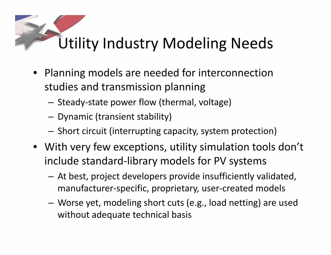
Utility Industry Modeling NeedsUtility Industry Modeling Needs
• Planning models are needed for interconnection studies and transmission planning– Steady‐state power flow (thermal, voltage)
– Dynamic (transient stability)
– Short circuit (interrupting capacity, system protection)
With f ti tilit i l ti t l d ’t• With very few exceptions, utility simulation tools don’t include standard‐library models for PV systems
At best project developers provide insufficiently validated– At best, project developers provide insufficiently validated, manufacturer‐specific, proprietary, user‐created models
– Worse yet, modeling short cuts (e.g., load netting) are used without adequate technical basis

Utility Industry Modeling NeedsUtility Industry Modeling Needs• NERC Integration of Variable Generation Task Force (IVGTF) has identified the lack of planning models as(IVGTF) has identified the lack of planning models as major barrier to variable generation integration
“Validated generic non confidential and public standard power flow andValidated, generic, non‐confidential, and public standard power flow and stability (positive‐sequence) models for variable generation technologies are needed. Such models should be readily validated and publicly available to power utilities and all other industry stakeholders Model parameters shouldpower utilities and all other industry stakeholders. Model parameters should be provided by variable generation manufacturers and a common model validation standard across all technologies should be adopted. The NERC Planning Committee should undertake a review of the appropriate Modeling, g pp p g,Data and Analysis (MOD) Standards to ensure high levels of variable generation can be simulated.”
Source: NERC Special Report Accommodating High Levels of Variable GenerationSource: NERC Special Report, Accommodating High Levels of Variable Generation,
http://www.nerc.com/files/IVGTF_Report_041609.pdf
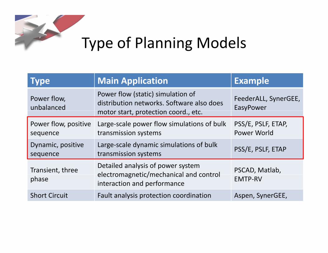
Type of Planning ModelsType of Planning Models
T M i A li ti E lType Main Application Example
Power flow, unbalanced
Power flow (static) simulation of distribution networks. Software also does
t t t t ti d t
FeederALL, SynerGEE,EasyPower
motor start, protection coord., etc.y
Power flow, positive sequence
Large‐scale power flow simulations of bulk transmission systems
PSS/E, PSLF, ETAP, Power World
D i i i L l d i i l i f b lkDynamic, positive sequence
Large‐scale dynamic simulations of bulk transmission systems
PSS/E, PSLF, ETAP
Transient, three Detailed analysis of power system electromagnetic/mechanical and control
PSCAD, Matlab, phase
electromagnetic/mechanical and control interaction and performance
EMTP‐RV
Short Circuit Fault analysis protection coordination Aspen, SynerGEE,

WECC Renewable Energy Modeling Task Force
NERCNERC
WECCWECC Other RE
Other RE
PCCPCC
TSSTSS Other SubOther Sub
Other Standing Committees
Other Standing Committees
TSSTSS
MVWGMVWG Other WGOther WG
Other Sub Comm.
Other Sub Comm.
REMTFREMTF Other TF
Other TF
WindWind SolarSolar
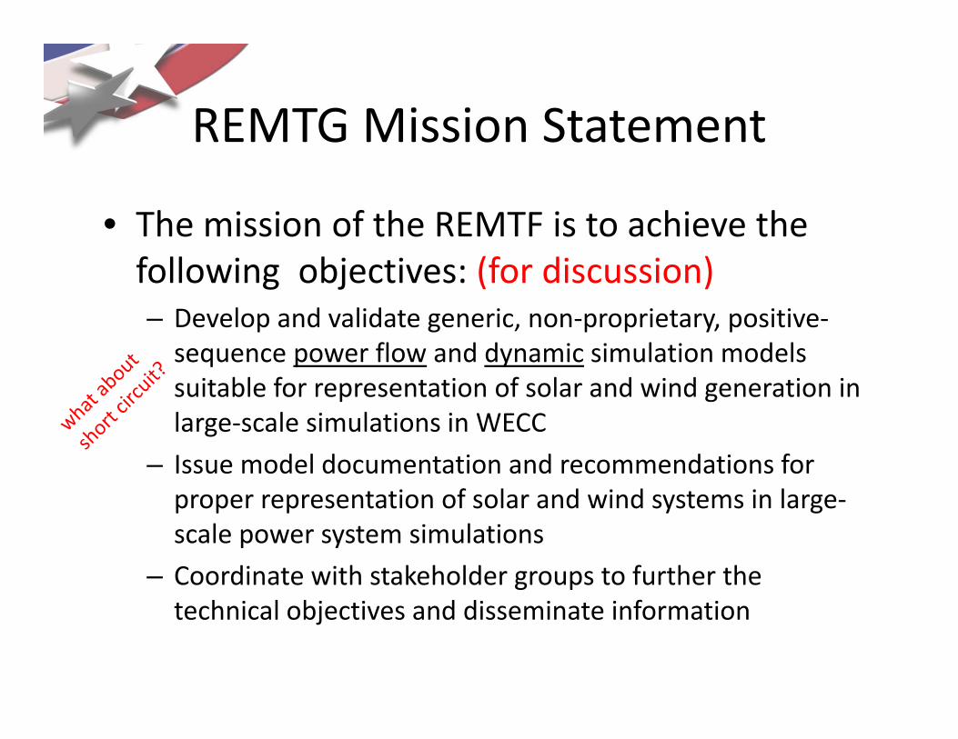
REMTG Mission StatementREMTG Mission Statement
• The mission of the REMTF is to achieve theThe mission of the REMTF is to achieve the following objectives: (for discussion)– Develop and validate generic non‐proprietary positive‐Develop and validate generic, non proprietary, positivesequence power flow and dynamic simulation models suitable for representation of solar and wind generation in l l i l ti i WECClarge‐scale simulations in WECC
– Issue model documentation and recommendations for proper representation of solar and wind systems in large‐p p p y gscale power system simulations
– Coordinate with stakeholder groups to further the t h i l bj ti d di i t i f titechnical objectives and disseminate information

PV System Power Flow ModelsPV System Power Flow Models
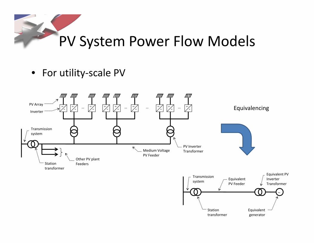
• Large PV systems– Single generator representation
• Requires “equivalencing” of PV collector system
• Explicit representation of station transformer
• Based on WECC Modeling Guide for Wind Generation
– Use conventional generation with proper reactive limits and reactive control mode
• Constant PF, constant reactive power, voltage regulation
• Distributed PV Systems– Approach TBD
PV System Power Flow Models
• For utility‐scale PV
PV System Power Flow Models
For utility scale PV
= = = = = = = = =PV ArrayE i l i… … ……= .
. ~= .. ~
= .. ~
= .. ~
= .. ~
= .. ~
= .. ~
= .. ~
= .. ~Inverter
y
Transmission system
Equivalencing
Station t f
Other PV plant Feeders
Medium Voltage PV Feeder
PV Inverter Transformer
Equivalent PV Feeder
transformer
Transmission system
Equivalent PV Inverter Transformer
~
Station transformer
Equivalent generator

PV System Power Flow Models
• For distributed PV
PV System Power Flow Models
For distributed PVTransmission
system
Unit StationTransmission
Distribution system
Unit Station Transformer
system
Unit Station Transformer (LTC)
Utility‐scale PV
~
LoadDG
Residential
Commercial
Pad/Pole Transformer
LoadDG
Model feeder impedance for dynamics(e.g., WECC Composite Load Model)

PV System Dynamic ModelsPV System Dynamic Models
• Basic Specifications (for discussion)– Approximate aggregate dynamic response of multiple grid‐connected inverters in a PV plant
bl f l f d d h– Suitable for simulation of during grid events with constant irradiance
• 3‐phase faults (up to 9 cycles), 1‐phase faults (up to 30 cycles), p ( p y ), p ( p y ),frequency events, oscillatory events
– Numerically stable with time steps of ¼ to ½ cycle
I l d t f i ti d i t l ti &– Includes set of existing and emerging control options & capabilities
• Volt/Var control options, power control (ramp rate, output limit), frequency support
PV System Dynamic ModelsPV System Dynamic Models
• Basic Specifications (continued)– Has user‐settable parameters (gains, time constants, etc) for representation of manufacturer‐specific hardware
l f fl h l– Initializes from power flow without special scripts
– Validated!
St i t t i i l ti PV t t• Strong interest in simulating PV output variability in dynamic simulations
d l f h d d l (??) ld b– A module separate from the dynamic model (??) could be used to inject PV power profile (similar to PSLF GENCLS)
• User‐specified P,Q vs. time seriesp ,
• User‐specified Irradiance vs. time series (user needs to account for effect of tracking, size of plant, etc)
PV System Dynamic ModelsPV System Dynamic Models
• Model Validation– Critical part of model development
– Need to demonstrate that models can match • Field recordings• Field recordings
• Laboratory test
• Manufacturer high‐order (EMTP‐type) models
– Need assistance from manufacturers
• User experience and model testing should guide d l i t timodel improvements over time
A Potential Implementationp
• Basic Assumptions– PV array is voltage‐ and irradiance‐dependent current source
• Temperature impacts can be neglected
• Current response to voltage or irradiance transient is instantaneousCurrent response to voltage or irradiance transient is instantaneous (algebraic)
– Inverters are high‐frequency PWM, current‐regulated, voltage sourcevoltage‐source
• With ¼ cycle time step, current regulator and modulator dynamics may be neglected… perhaps
• Primary dynamics are due to inverter dc capacitor bank, dc voltage regulator and ac phase lock algorithms
• Additional dynamics may be introduced to influence real and reactive power ramp rates
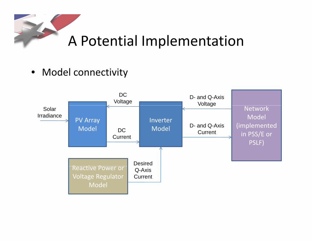
A Potential ImplementationA Potential Implementation
• Model connectivity
DC Voltage
D- and Q-Axis Voltage
Model connectivity
PV Array Model
Inverter Model
Network Model
(implemented in PSS/E or
Solar Irradiance
DC C t
D- and Q-Axis Current
Voltage
in PSS/E or PSLF)
R ti P
Current
Desired Reactive Power or Voltage Regulator
Model
Q-Axis Current

A Potential ImplementationA Potential Implementation
• PV array model – represent algebraically (can we ll i MPPT d i f id di b ?)
1.4
really ignore MPPT dynamics for grid disturbances?)
1
1.2
rent
(pu)
wer
(pu)
Increasing Irradiance
Increasing I di
0.6
0.8
Arr
ay C
urr
Arr
ay P
ow Irradiance
Increasing Irradiance
0
0.2
0.4
00.0 0.2 0.4 0.6 0.8 1.0 1.2 1.4
Array Voltage (pu)

A Potential ImplementationA Potential Implementation
• Inverter model – Similar to WT4 generic wind modelInverter model Similar to WT4 generic wind model

Questions and DiscussionQuestions and DiscussionQuestions and DiscussionQuestions and Discussion