development of nano/micro scale sectioning tools based on charged particle beam for biological...
TRANSCRIPT


Development of nano/micro scale sectioning tools based on charged particle beam for biological systems
Jing Fu Sanjay B. JoshiDepartment of Industrial and Manufacturing EngineeringThe Pennsylvania State University
Jeffrey M. CatchmarkDepartment of Agricultural and Biological EngineeringThe Pennsylvania State University

Background
• Future biomedical research will rely on “more detailed understanding of the vast networks of molecules that make up our cells and tissues, their interactions, and their regulation” (NIH Roadmap for Medical Researches)
Subramaniam, Current Opinion in Microbiology 2005
• The development of Electron Microscopy (EM) has bridged a gap between cellular structure and protein structure (Subramaniam, 2005)

Background - Bioimaging
• Electron Microscopy– Scanning Electron Microscopy (SEM)– Transmission Electron Microscopy (TEM)
• Sample Preparation– Chemical fixation– Resin embedded– Vitrification (Cryo-fixation)
• Amorphous ice by plunge freezing to <~136K• Immobilized instantly for in situ imaging
• Sectioning by microtome required for bulk samples– Vitrification only applies to sections of µm thickness– TEM requires thickness of several hundreds nanometers

Background – Charged Particle Beams
• Charged Particle Beam (Ion Beam, Electron Beam)– Advancements of Electrostatic optics
(ion beam) and Magnetic lenses (e-beam)
– Submicron feature patterning
• Focused Ion Beam (FIB)– Typical based on gallium ions (Ga+)– Digitally controlled with 3D geometry
capability– Larger material removal rate (ion vs.
photon, electron)

FIB for Biosectioning
• Frozen hydrated samples (cryo-fixed)– A preliminary study (Heymann, J. Structural Bio. 2006)– Plant cells, E.coli (Marko et al., Nature method, 2007), Mammalian
cells (McGeoch, J. Microscopy, 2007)
FIB milled Arabidopsis courtesy of Gang Ning at PSU
FIB milled E.coli and reconstruction (Nature method, 2007), with permission
from Michael Marko at Wadsworth Center

Advantages
• Provide in situ sectioning and imaging of cell structures or systems• Fully digitally controlled operations for “Slice and View” by dual beam
(FIB/SEM) system and 3D tomography • Less distortion or compression vs. conventional microtome• Occupational safety (risk of neuropathy using cryomicrotome)
Optical Image (scale: 20 μm) SEM Image (scale: 3 μm)
FIB milled frozen Acetobacter xylinum

Ion-Solid Interactions - Overview
en x
E
x
E
x
E
d
d
d
d
d
d

Challenges
• Ion-solid interactions– Limited study on ion sputtering in a cryogenic environment– Ultrahigh sputtering rate reported which invalidates conventional
models
• Process control– System Settings: ion energy, ion current, etc.– Process Parameters: temperature, target material, etc.
• Process characteristics– Surface morphology – Aspect ratio of features

Material Removal Rate Y
• Defined as Sputtering Yield (molecule/ion) or Sputtering Rate (µm3/nC)
• Classical model (For monatomic or alloys materials)– Linear Cascade Collisions (LSS) by Sigmund
– Nuclear sputtering dominant
• Monte Carlo simulation (SRIM/TRIM)

Setup
Control Units for Cryo Transfer
Preparation Chamber
Electron Beam Column
Ion Beam Column
FIB/SEM Main Chamber
Control Units for Cryo Transfer
Preparation Chamber
Electron Beam Column
Ion Beam Column
FIB/SEM Main Chamber
FEI Quanta 200 3D DualBeam (FIB/SEM) at Material Characterization Lab, Penn State University
• Ion Beam– Ga+, 10-30 keV– Beam Spot Size (Minimum 7
nm)
• Target Samples– Amorphous Solid Water
(ASW) by Vapor Deposition– Hyperquenching Glassy
Water (HGW) by Plunge Freezing
• Temperature– 83 K – 123K

Sputtering Rate of Solid H2O
• Previously limited to astrophysics since early 1980• Ion energy dependent (10 keV – 30 keV Ga+)
– Y=Yn+Ye , Magnitude of 10 µm3/nC at 30 keV (~0.3 µm3/nC for Si)
– Nuclear sputtering Yn Sn
– Electronic sputtering Ye (Se )2
0
10
20
30
40
50
60
5 10 15 20 25 30 35
Ion Energy (keV)
Spu
tte
ring
Ra
te (μ
m3 /
nC
)
8
4
12
Y
Ye
Yn
0
10
20
30
40
50
60
5 10 15 20 25 30 35
Ion Energy (keV)
Spu
tte
ring
Ra
te (μ
m3 /
nC
)
8
4
12
8
4
12
Y
Ye
Yn
J. Fu, S.B. Joshi, J.M. Catchmark, J. Vacuum Sci Tech A, to appear

Sputtering Rate of Solid H2O
• Temperature dependent– Y increases with the increase of T– Y(T)=Y(0)(1+αe-β/kT )
• Varied energy dissipation
0
20
40
60
80
70 80 90 100 110 120 130
Experiment
Fitted
Temperature (K)
Spu
tter
ing
Rat
e (μ
m3 /
nC)
8
4
12
16
0
20
40
60
80
70 80 90 100 110 120 130
Experiment
Fitted
Temperature (K)
Spu
tter
ing
Rat
e (μ
m3 /
nC)
8
4
12
16
8
4
12
16

Sputtering Rate of Solid H2O
• Incident angle dependent– Maximum of Y at 70 degree– Y(θ)=cos-1.3Y(0) from 0 degree to 70 degree
• Energy transfer by Ion closer to the surface
• Decrease of ion effective volume at high θ
0
10
20
30
40
0 10 20 30 40 50 60 70 80 90
Incident Angle θ (deg)
Fitted model curveSRIM simulation
Sp
utte
ring
Ra
te (
μm
3/n
C)
0
10
20
30
40
0 10 20 30 40 50 60 70 80 90
Incident Angle θ (deg)
Fitted model curveSRIM simulation
Sp
utte
ring
Ra
te (
μm
3/n
C)

Surface Morphology
• Submicron features developed on ice upon ion sputtering• Various morphology, dome/pillar, terraces, etc.• Incident angle dependant
FIB milled water ice at different incident angle (100 pA, 30 keV, 93 K)
Redeposition
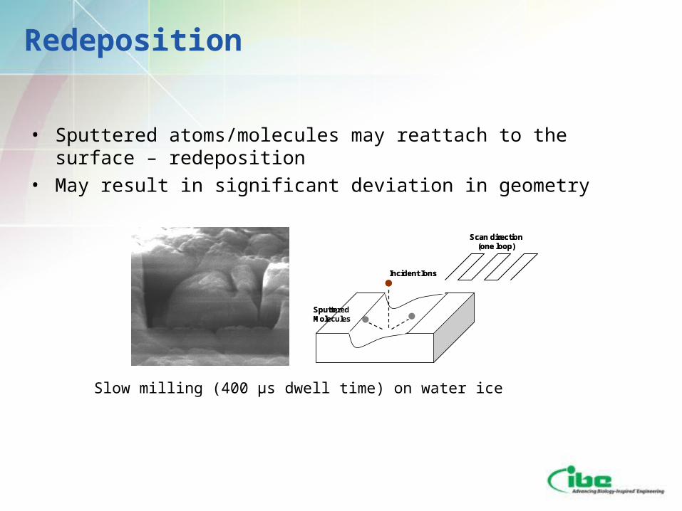
• Sputtered atoms/molecules may reattach to the surface – redeposition
• May result in significant deviation in geometry
Scan direction (one loop)
Incident Ions
Sputtered Molecules
Scan direction (one loop)
Incident Ions
Sputtered Molecules
Slow milling (400 µs dwell time) on water ice

Process Simulation
300 nm trench milled on water ice at 93 K
Cylindrical features of diameter 5 µm milled on water ice at 93 K
Results of process simulation
Results of process simulation

Closing Remarks
• Highlights– Development of charged particle beams (ion and possible electron
beam) as cryomicrotome for sectioning biological samples– Modeling of ion sputtering (keV Ga+) water ice– Investigation of process and system variables
• Future development– Cryo-transfer methods and protocols– Ion interactions with macromolecules and process database– Biological effects for development of cell surgery

Acknowledgements
• Lucille A. Giannuzzi, FEI company• Michael Marko, Wadsworth Center• Gang Ning, Penn State University• Sriram Subramaniam, NIH
• Use of facilities at the PSU Site of the NSF NNIN under Agreement # 0335765
• Cryo-FIB seed fund, MCL, Penn State University

Thank you
Thin section of ice about 400nm ready for TEM lift out (scale: 5 μm )
Top View
FIB milled Ice section 93 K