development of nano-oxide dispersed 304l steels by ... · austenitic stainless steel (304l) ......
TRANSCRIPT

DOI: http://dx.doi.org/10.1590/1980-5373-MR-2015-0593Materials Research. 2016; 19(1): 175-182 © 2016
*e-mail: [email protected]
1. IntroductionFerritic-martensitic steels are widely used in nuclear
power plants due to their excellent void swelling resistant property but their creep resistant property is poor, this is due to the fact that they have open body centre cubic structure. As an alternative, austenitic steels are being studied as these steels have excellent creep resistance at high temperature, and reasonable corrosion and oxidation resistance as compared to ferritic or martensitic steels. In addition to that, these steels have better chemical compatibility (such as resistance to stress corrosion cracking, irradiation assisted stress corrosion cracking (IASCC) with fuel and coolant materials in a nuclear reactor. Therefore, studies on austenitic stainless steels in place of ferritic martensitic steels are the major concern in future nuclear and structural applications. Austenitic stainless steel (304L) is a main candidate material in residual heat removal circuits of pressurised water reactors applications.1-4 As nuclear applications require high-temperature strength of the candidate material, improving strength of austenitic stainless steels is a challenge. By dispersing fine oxide particles into austenitic matrix higher strength of the material was achieved.5 Recently, considerable amount of research work has been carried out on oxide dispersion strengthened (ODS) steels as candidate materials for fusion reactor structural components. Enhanced properties of oxide dispersion strengthened steels can be attributed to the homogenous distribution of nano-oxides in the alloy matrix.
6 High density of dislocations in the alloy results in better void formation resistance. 7
There have been reports suggesting that, with higher dislocation densities in austenitic stainless steels better irradiation properties can be achieved. Investigations on size and density of cavities revealed that cavities formed upon irradiation in ODS steels are smaller in size and have double the density compared to conventional steels. Hence ODS steels have better swelling resistance.8 Austenitic stainless steels produced by powder metallurgical route have yielded better mechanical (UTS/YS) properties compared to same alloys produced by traditional techniques with loss of ductility.9 Although alternative routes have been experimented on and suggested to disperse oxide nano-particles into steel matrix,10 powder metallurgy route is widely used method to produce oxide dispersion strengthened steels.
Mechanical alloying is a solid state synthesis process that consists of repeated cold-welding, fracturing, dynamic recrystallization and mechanically activated inter-diffusion among the powder particles in a high energy ball mill.11 It has been repeatedly proven that reduction of grain size can substantially improve properties of the alloy. By using simple equipment i.e. a planetary ball mill, powders of few microns size can be brought to nano sized level, hence a nano- structured stainless steel is produced.12 In addition to the structure refinement of powder particles, mechanical alloying has few characteristic benefits such as: dissimilar metal elements can be alloyed at room temperature by high energy mechanical milling; nano-sized oxide particles
Development of nano-oxide dispersed 304L steels by mechanical milling and conventional sintering
Sambaraj Sravan Kumara, Sandeep E Sa, S.B. Chandrasekharb, Swapan Kumar Karaka*
aDepartment of Metallurgical and Materials Engineering, National Institute of Technology, 769008, Rourkela, Odisha, India
bInternational Advanced Research Centre for Powder Metallurgy and New Materials – ARCI, Balapur P.O., 500005, Hyderabad, Telangana, India
Received: October 3, 2015; Accepted: November 26, 2015
In the present work an attempt has been made to synthesize 304L stainless steels alloy powders with nominal compositions 70.00Fe-19.00Cr-11.00Ni (alloy A), 69.00Fe-19.00Cr-11.00Ni- 1.0 Y2O3(alloy B), and 69.00Fe-19.00Cr-11.00Ni- 1.0 TiO2(alloy C), (all in wt.%) by mechanical milling and conventional sintering at 1150°C for 1.0 hour in argon atmosphere. Extensive characterization has been done by SEM, TEM, X-ray diffraction analysis, EDS and particle size analysis at different stages of milling. The minimum crystallite size of powder at final stage of milling was found in the range of 20-25 nm. The bulk hardness values of base and Oxide dispersion strengthened alloys are 2.628 GPa, 4.125 GPa (average) respectively. Wear resistance of TiO2 dispersed alloy C is found to be superior to that of yttria dispersed alloy B and base alloy A. The nanometric oxide (20-25 nm) particles uniformly dispersed in the alloy matrix contribute to superior mechanical properties.
Keywords: Oxide dispersion strengthened stainless steels, Mechanical milling, conventional sintering, Scanning electron microscopy, X-ray diffraction analysis, mechanical properties.
Kumar et al.176 Materials Research
added to the base alloy powder can be effectively dispersed into its matrix and get further refined during the milling process. Such an extensive refinement of these nano-oxides leads to ultra fine complex oxide particles which can be precipitated with suitable heat treatment.13 Nano-structured materials exhibit improved strength and hardness along with very high diffusion rates. High diffusion rates of these materials results in reduced sintering duration for powder consolidation.14 Powder consolidation by conventional sintering (electrically-heated) is a very commonly used sintering technique, as compared to other techniques such as microwave sintering and spark plasma sintering. In the case of conventional sintering, the compacts get radiatively heated and at high temperatures this leads to microstructural coarsening. However, consolidation of 316L austenitic steel involving microwave sintering which employs high heating rates has failed to produce a better sintered compact, low hardness; strength and ductility with lower sintered density were reported, compared to a conventionally sintered one. These inferior properties of microwave sintered 316L steel were correlated with irregular and elongated pore morphology.15 Conventional sintering of mechanically alloyed austenitic stainless steel powders has resulted in improved precipitation of oxide particles in the recrystallized grains.16
2. Experimental procedure2.1 Mechanical milling of austenitic stainless
steel powderPre-alloyed powder of 304L austenitic stainless steel
(Alloy A: average particle size ~ 30–80 µm) is subjected to milling by a Fritsch PM400 planetary ball mill, operated at 300 rpm using stainless steel vials (250 ml) and balls (10mm diameter) for several milling time (0h, 1h, 5h,10h,20h,30h and 40h). The nano-Y2O3 (~40nm) and nano-TiO2 (~40nm) with 1.0 wt % each were added to 40 h milled powders by sonication and blending process to obtain alloy B with nominal composition of 69.00Fe-19.00Cr-11.00Ni- 1.0 Y2O3 and alloy C with nominal composition of 69.00Fe-19.00Cr-11.00Ni- 1.0 TiO2, all in wt.%, respectively. Milling was carried out in toluene medium with a ball-to-powder ratio (BPR) of 10:1. Toluene acts as an additive (diluents/coolant) and restricts the combustion event. It avoids inter-particle welding during collisions, which results in reduction of particle size. 17 The phase evolution of powder samples at different stages of mechanical milling (0h, 1h, 5h,10h,20h,30h and 40h) and sintered pellets (alloy A, alloy B and alloy C) were studied by XRD analysis using the Cu Kα (λ=1.542Å) in a Philips X-pert MPD X-ray diffractometer. Microstructural characterisation of milled powders at different stages of milling was carried out by using JEOL/EO scanning electron microscope. Surface morphology and EDS of sintered pellets were done using FESEM (NOVA NANOSEM 450). To obtain details of internal structure transmission electron microscopy of milled powders and sintered products was done using JEOL JEM 2100 high resolution transmission electron microscope (HRTEM) operated at 200KV.
2.2 Consolidation of three different austenitic stainless steel powders by sintering
Mechanically milled powders of alloy A (pure 304L austenitic stainless steel), alloy B (nano- Y2O3 added) and alloy C ( nano- TiO2 added) are compacted under a uniaxial pressure of 750MPa in hardened steel cylindrical die for 3 minutes holding time and were subsequently sintered at 1150oC for 1h in a tube furnace with controlled argon gas atmosphere. Densities of sintered pellets were measured by using Archimedes principle. Mechanical properties (mainly hardness and wear) of the sintered products were carried out by using universal testing machine. Microhardness measurements of all the samples sintered at 1150oC were carried out by using LECO (LM248AT) Vickers micro-hardness testing machine with an applied load of 50gf for a dwell time of 10s. For better evaluation, the hardness value of the sample was calculated as average of at least 10 hardness measurement readings. Wear testing of the sintered samples was done by using a DUCOM TR-208-M1 ball on plate type wear testing instrument having a diamond indenter. The device was operated at 0.084 m/s speed and 500g load for 5 min at the ambient temperature (22–25°C) and humidity (50-55%). To study the surface damage and topology of the worn surfaces generated due to wear testing, the samples were examined using JEOL/EO scanning electron microscope at different magnifications.
3. Results and Discussion3.1 Phase evolution of milled powders and
sintered products by XRD analysisFig.1 (a) shows series of XRD patterns of pre-alloyed
304L steel (alloy A) powder milled for different increasing time periods (0 h, 1 h, 5 h, 10 h, 15 h, 20 h, 30 h and 40 h). In the XRD patterns of initial pre-alloyed powder (0h) high intensity peaks of austenitic phase can be observed. It is also relevant peaks are very sharp in nature in the initial stages of milling then they gradually decreases as milling time increases. This due to the fact that the crystallite size decreases with increasing milling time which leads to peak broadening. Increase in full-width at half-maximum (FWHM) with increasing milling time depict that both plastic strain build up and reduction in crystallite size. Fig.1 (b) shows the XRD patterns of alloy A, alloy B, and alloy C all sintered at 1150°C for 1 hour in Argon atmosphere.
It appears that FCC γ austenite phase is the predominant constituent and also the presence of BCC α ferrite phase has been identified in the sintered product. Similar kind of observations have been found by Shahsanka et al.12 In addition to the phases present in alloy A, Y2O3 and TiO2 phases were also observed in XRD profile of alloy B and alloy C, respectively. Particle size analysis of different stages of milled powder shows the reduction of average particle size from 51µm to 3.5 µm with increase of milling time. Fig.2 shows the crystallite size and lattice strain of the powder, calculated by using Williamson–Hall equation (Eq. 1), plotted against milling time.
0.94 4cos sinDλ β θ = + η θ
(1)

Development of nano-oxide dispersed 304L steels by mechanical milling and conventional sintering2016; 19(1) 177
It is observed that the crystallite size gradually decreases and residual strain increases with increase in milling time. The average crystallite size of pre-alloyed powder before milling (alloy A) is 210 nm while after 40h of milling it decreased to 20 nm.
3.2 Phase evolution of milled powders and sintered products by SEM and EDS analysis
3.2.1 SEM and EDS analysis of mechanically alloyed powders
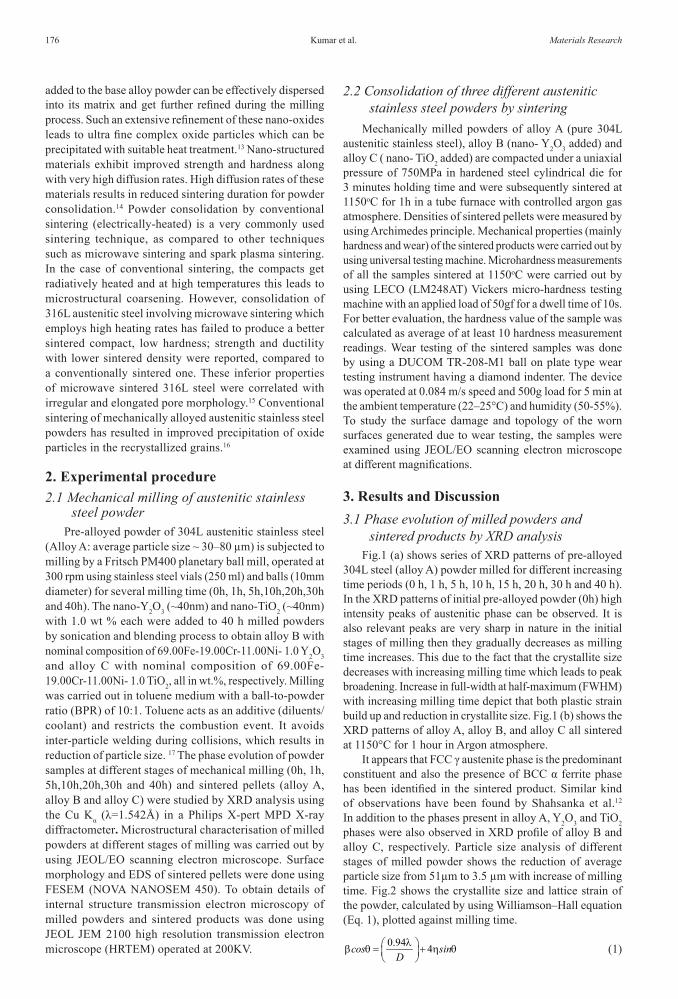
SEM micrographs of unmilled (0h) and milled austenitic stainless steel powders at different time intervals (5 h, 10 h, 20 h and 40 h) are shown in Fig. 3. It is clear from the images that there is substantial variation in morphology and size of the powder particles during course of milling. It is found that powder particles at unmilled condition (0h) were irregular in shape and larger size. During the early stages of milling,
the stainless steel powder particles are soft and ductile. Soft particles have tendency to weld together and form particles of larger sizes. As milling continues, the ductile nature of the austenitic stainless steel powder particles leads to particle agglomeration and after completing 5h of milling the size of the powder particles gets reduced and also these particles get flattened. At the later stages of milling, the flat powder particles lamellae weld together to form a single large lamella. It is observed that powder particles milled at 15 h are more spherical in shape and their size distribution is uniform. Apparent particle size of 15h milled product is analyzed by SEM micrograph and the average particle size from particle size analysis with calculated standard deviation values are shown in table 1. It may be demonstrated that there is a possibility of work hardening phenomenon in the sub-micron size particles from 15h to 20h of milling. Particles size analysis shows increase in lattice strain with milling time, which can be directly related to increase in work hardening of the powder particles. Increase in work hardening is linear up to 30h of milling as a result the particles gradually lose ductility and becomes brittle in nature. Plastic deformation and subsequent work hardening have lead to fatigue and fragmentation of brittle powder particles. Work hardening of powder particles during milling was reported earlier by Shahsanka et al.(10) Beyond 30h of milling although there was no significant change in powder morphology, average size of the particles was reduced from 20.58µm to 5.12µm. Compared to other milling times, the minimum to maximum size variation of the powder particles was found to be least after 40h milled condition. Hence it can be suggested that particle size distribution upon 40h of milling is relatively more uniform as compared to the previous milling stages. Small particle size helps in improving densification of the powder due to large surface to volume ratio. Initially the average particle size is about 50 µm, and then it reduced to 3.5 µm after 40h milling.
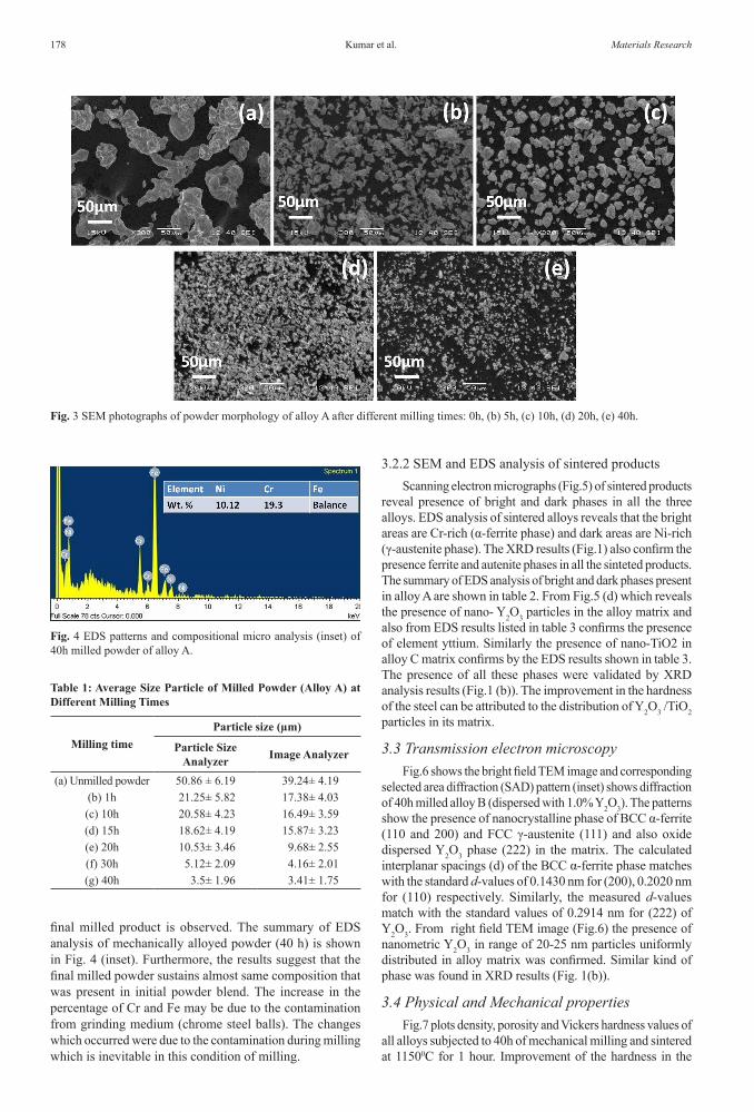
Fig.4 shows the EDS pattern of 40 h milled powder. From Fig. 4 the presence of Fe, Cr and Ni elements in the
Fig. 1 X-ray diffraction patterns of mechanically milled powders (a) Pre-alloyed powder at different milling times 0 h to 40 h, and (b) sintered products alloy A, alloy B, alloy C.
Fig. 2 Variation in crystallite size and residual strain with milling times of pre-alloyed powder (alloy A).
Kumar et al.178 Materials Research
final milled product is observed. The summary of EDS analysis of mechanically alloyed powder (40 h) is shown in Fig. 4 (inset). Furthermore, the results suggest that the final milled powder sustains almost same composition that was present in initial powder blend. The increase in the percentage of Cr and Fe may be due to the contamination from grinding medium (chrome steel balls). The changes which occurred were due to the contamination during milling which is inevitable in this condition of milling.
3.2.2 SEM and EDS analysis of sintered productsScanning electron micrographs (Fig.5) of sintered products
reveal presence of bright and dark phases in all the three alloys. EDS analysis of sintered alloys reveals that the bright areas are Cr-rich (α-ferrite phase) and dark areas are Ni-rich (γ-austenite phase). The XRD results (Fig.1) also confirm the presence ferrite and autenite phases in all the sinteted products. The summary of EDS analysis of bright and dark phases present in alloy A are shown in table 2. From Fig.5 (d) which reveals the presence of nano- Y2O3 particles in the alloy matrix and also from EDS results listed in table 3 confirms the presence of element yttium. Similarly the presence of nano-TiO2 in alloy C matrix confirms by the EDS results shown in table 3. The presence of all these phases were validated by XRD analysis results (Fig.1 (b)). The improvement in the hardness of the steel can be attributed to the distribution of Y2O3 /TiO2 particles in its matrix.
3.3 Transmission electron microscopyFig.6 shows the bright field TEM image and corresponding
selected area diffraction (SAD) pattern (inset) shows diffraction of 40h milled alloy B (dispersed with 1.0% Y2O3). The patterns show the presence of nanocrystalline phase of BCC α-ferrite (110 and 200) and FCC γ-austenite (111) and also oxide dispersed Y2O3 phase (222) in the matrix. The calculated interplanar spacings (d) of the BCC α-ferrite phase matches with the standard d-values of 0.1430 nm for (200), 0.2020 nm for (110) respectively. Similarly, the measured d-values match with the standard values of 0.2914 nm for (222) of Y2O3. From right field TEM image (Fig.6) the presence of nanometric Y2O3 in range of 20-25 nm particles uniformly distributed in alloy matrix was confirmed. Similar kind of phase was found in XRD results (Fig. 1(b)).
3.4 Physical and Mechanical propertiesFig.7 plots density, porosity and Vickers hardness values of
all alloys subjected to 40h of mechanical milling and sintered at 11500C for 1 hour. Improvement of the hardness in the
Fig. 3 SEM photographs of powder morphology of alloy A after different milling times: 0h, (b) 5h, (c) 10h, (d) 20h, (e) 40h.
Fig. 4 EDS patterns and compositional micro analysis (inset) of 40h milled powder of alloy A.
Table 1: Average Size Particle of Milled Powder (Alloy A) at Different Milling Times
Milling timeParticle size (µm)
Particle SizeAnalyzer Image Analyzer
(a) Unmilled powder 50.86 ± 6.19 39.24± 4.19(b) 1h 21.25± 5.82 17.38± 4.03(c) 10h 20.58± 4.23 16.49± 3.59(d) 15h 18.62± 4.19 15.87± 3.23(e) 20h 10.53± 3.46 9.68± 2.55(f) 30h 5.12± 2.09 4.16± 2.01(g) 40h 3.5± 1.96 3.41± 1.75

Development of nano-oxide dispersed 304L steels by mechanical milling and conventional sintering2016; 19(1) 179
Fig. 5 FE-SEM micrographs of alloys A, B and C at different magnifications: Alloy A (a), (b); Alloy B (c), (d); alloy C (e),(f).
Table 2: Summary of EDS analysis of bright phase and dark phase in alloy A.
Elements Bright phaseWt %
Dark phaseWt %
Fe 73.17 72.96Cr 23.08 8.81Ni 3.75 18.23
Table 3: Summary of EDS analysis of all the three alloys sintered at 1150 °C.
AlloyElements (wt %)
Cr Ni Ti Y O FeA 19.4 10.96 - - 0.03 BalanceB 19.29 10.92 - 0.37 0.54 BalanceC 19.21 10.94 0.58 - 0.38 Balance

Kumar et al.180 Materials Research
Fig.6 TEM images of alloy B powder sample after 40 h of mechanical milling
Fig. 7 Variation of hardness and density plot of the consolidated alloys
present alloys can be attributed to reduction of grain size by mechanical milling, according to the Hall-Petch equation and uniform dispersion of oxide particles in the base alloy matrix. Since average particle size is same for alloys B and C, the factors resulting in variation of hardness of these alloys are density of the sample and type of oxide dispersion.
As alloy A does not contain any oxide dispersions its hardness value is the lowest recorded among the three alloys. For comparison hardness values of consolidated pure TiO2 and pure Y2O3, which are 10.29 GPa and 7.5 GPa respectively are noted. It is observed that hardness value is more in case of alloy C which contains 1 wt. % TiO2, followed by alloy B with 1 wt. % Y2O3. The high hardness of alloy C can be attributed to its high densification, more than 90%, among the other two alloys i.e. 88.6% for alloy A and 89.35% for alloy B and also to the hardness of TiO2 which is greater than that of Y2O3.
Fig. 8 shows the plot for the variation of wear depth (µm) vs. time (s) of alloy A, alloy B, and alloy C. It is evident from the plot the maximum wear depth value of alloy C is the least among other three alloys. This result suggests the superior wear resistance of TiO2 dispersed alloy C over Y2O3 dispersed alloy B. While the maximum wear depth values of both alloy B and alloy C were observed to be lower than that of alloy A, indicating the improvement in wear resistance behaviour by oxide dispersion (Y2O3/TiO2) in general.

Development of nano-oxide dispersed 304L steels by mechanical milling and conventional sintering2016; 19(1) 181
Scanning electron microscopy at the wear scar region which were carried out to better understand the wear behaviour of the alloy B and alloy C showed difference in width of wear tracks. The wear track of Alloy B (shown in Fig.9 (b)) is larger in size than that of alloy C (shown in Fig.9 (a)) indicating the resistance to wear is higher in alloy C among the two alloys.
EDS results of wear scar region of both alloy B and alloy C further explains the wear mechanism involved in the respective alloys. It was found that chemical composition of the worn surfaces changes during wear. Table 4 lists the
chemical composition results (in wt. %) of the wear scar regions obtained from EDS analysis. From XRD results of sintered products it is know that oxygen exists as TiO2 which contributes to the overall wear resistance of the alloy, in addition to TiO2 the Ni-Ti intermetallic Ni4Ti3 as Ni is present in higher amounts (compared to Ni in total alloy composition) can be a major factor in improved wear and other mechanical properties of the alloy. Similar kind of results was obtained in case of alloy B, except for the higher oxygen content in this alloy than that of in alloy C. However the variation in oxygen content from interior region of wear scar to the scar boundary was observed commonly in both the alloys. The variation in oxygen content across the boundary of wear scar was reported earlier by S.K. Karak et al,(11) in case of nano-Y2O3 dispersed ferritic steel which was developed by mechanical alloying and hot isostatic pressing.
4. Summary and ConclusionsIn the present study, a comprehensive effort has been
arranged to develop 1.0 wt% nano-Y2O3 or TiO2 dispersed 304L austenitic alloys by mechanical alloying and subsequent consolidation by conventional sintering at 1150° C for 1.0 hour in argon atmosphere. Through close analysis of the results in terms of synthesis and characterization, sintering, density, hardness, and wear resistant property in three set of alloys, a new perceptive on structure-property correlation has distended about nano-oxide dispersed ODS 304L austenitic alloys. The summary and conclusions of the current investigations are primed as follows:
• Mechanical alloying is a novel technique for the synthesis of nano-Y2O3 and nano-TiO2 dispersed ODS 304L austenitic alloys.
• XRD analysis of the milled alloy powder shows that Cr and Ni peaks are completely dissolved in Fe matrix in course of high-energy ball milling for 0-1h. The interesting phenomenon is that the new ferrite peak α and austenitic peak γ have been observed after 1 h of milling, and after 40 h of milling only austenitic peak γ is present.
Table 4: EDS analysis results of alloy C and alloy B wear scar region.
ElementAlloy C (wt. %)
(At the boundary) (wear scar interior)
Alloy B (wt. %)(At the boundary)
(wear scar interior)O K 6.86 9.45 10.66 7.22Ti K 0.46 0.08 -- --Y L -- -- 0.43 0.47Cr K 7.61 7.06 9.79 9.94Fe K 64.87 68.26 48.85 63.58Ni K 20.20 15.16 17.45 18.80
Fig. 9 SEM micrographs of wear tracks (a) nano-TiO2 dispersed alloy C (b) nano-Y2O3 dispersed alloy B.
Fig. 8 Variation of wear depth vs. time of the sintered products

Kumar et al.182 Materials Research
• Reduction in crystallite size of the parent matrix phase (γ phase) to 210-20 nm with increase of milling time is observed. Particle size analysis of different stages of milled powders show the reduction of apparent particle size to 51µm to 3.5µm with increase of milling time. The similar kind of trends has been found by SEM analysis that the average particles size in range of 40µm to 3.4µm with increase in milling time.
• Presence of the nanometric (20-35 nm) dispersed phases (nano-Y2O3or nano-TiO2) in 304L austenitic matrix are confirmed by TEM and FESEM analysis.
• Alloy C (nano-TiO2 dispersion) consistently records superior property in terms of density, hardness and wear resistance as compared to that of alloy A and alloy B. The high hardness values of ODS alloys may be due to uniformly distributed oxide particles in the alloy matrix.
Therefore, by evaluation of the above mentioned conclusions it can be recommended that mechanical alloying followed by conventional sintering with nano-oxide dispersed matrix offers attractive mechanical properties.
References1. Baldev R, Vijayalakshmi M, Vasudeva Rao PR, Rao KB.
Challenges in materials research for sustainable nuclear energy. MRS Bulletin. 2008; 33(4):327-337. http://dx.doi.org/10.1557/mrs2008.67
2. Shulga AV. A comparative study of the mechanical properties and the behaviour of carbon and boron in stainless steel cladding tubes fabricated by PM HIP and traditional technologies. Journal of Nuclear Materials. 2013;434(1-3):133-140. doi:10.1016/j.jnucmat.2012.11.008
3. Le Pécheur A, Curtit F, Clavel M, Stephan JM, Rey C. Thermo-mechanical FE model with memory effect for 304L austenitic stainless steel presenting microstructure gradient. International Journal of Fatigue. 2012;45:106-115. doi:10.1016/j.ijfatigue.2012.05.016
4. Murty KL, Charit I. Structural materials for Gen-IV nuclear reactors: Challenges and opportunities. Journal of Nuclear Materials. 2008; 383(1-2):189-195.
5. Zhangjian Zhou, Shuo Yang, Wanhua Chen, Lu Liao, Yingli Xu. Processing and characterization of a hipped oxide dispersion strengthened austenitic steel. Journal of Nuclear Materials. 2012; 428: 31-34. DOI: 10.1016/j.jnucmat.2011.08.027
6. Kim TK, Bae CS, Kim DH, Jang J, Kim SH, Lee CB, Hahn D. Microstructural observation and tensile isotropy of an austenitic ODS steel. Nuclear Engineering and Technology. 2008; 40:305-310. http://kns.org/jknsfile/v40/JK0400305.pdf
7. Arzt E, Behr R, Gohring E, Grahle P, Mason RP. Dispersion strengthening of intermetallics. Materials Science and Engineering A. 1997; 22: 234–236.
8. Kazimierzak B, Prignon JM, Fromont RI. An ODS material with outstanding creep and oxidation resistance above 1100°C. Materials & Design. 1992;13(2): 67-70.
9. Susila P, Sturm D, Heilmaier M, Murty BS, Subramanya Sarma V. Microstructural studies on nanocrystalline oxide dispersion strengthened austenitic (Fe–18Cr– 8Ni–2W–0.25Y2O3) alloy synthesized by high energy ball milling and vacuum hot pressing. Journal of Materials Science. 2010;45(17):4858–4865.
10. Verhiest K, Almazouzi A, De Wispelaere N, Petrov R, Claessens S. Development of oxides dispersion strengthened steels for high temperature nuclear reactor applications. Journal of Nuclear Materials. 2009;385(2):308-311.
11. Karak SK, Vishnu CS, Witczak Z, Lojkowski W, Dutta Majumdar J, Manna I. Studies on wear behavior of nano-Y2O3 dispersed ferritic steel developed by mechanical alloying and hot isostatic pressing. Wear. 2010;270(1-2):5-11. DOI: 10.1016/j.wear.2010.08.021
12. Shashanka R, Chaira D. Development of nano-structured duplex and ferritic stainless steels by pulverisette planetary milling followed by pressureless sintering. Materials Characterization. 2015;99:220–229.
13. Yingli Xu, Zhangjian Zhou, Ming Li, Pei He. Fabrication and characterization of ODS austenitic steels. Journal of Nuclear Materials. 2011;417(1-3):283-285.
14. Suryanarayana C, Nasser Al-Aqeeli. Mechanically alloyed nanocomposites. Progress in Materials Science. 2013;58(4):383-502.
15. Panda SS, Singh V, Upadhyaya A, Agrawal D. Sintering response of austenitic (316L) and ferritic (434L) stainless steel consolidated in conventional and microwave furnaces. Scripta Materialia. 2006;54(12):2179-2183.
16. Alamo A, Lambard V, Averty X, Mathon MH. Assessment of ODS-14%Cr ferritic alloy for high temperature applications. Journal of Nuclear Materials. 2004;329-333(1-3):333-337.
17. Suryanarayana C. Mechanical alloying and milling. Progress in Materials Science. 2001;46(1-2):1-184,