development of high-performance soft robotic fish by
TRANSCRIPT
Research ArticleDevelopment of High-Performance Soft Robotic Fish byNumerical Coupling Analysis
Wenjing Zhao ,1 Aiguo Ming,2 and Makoto Shimojo2
1College of Mechanical Engineering, Zhejiang University of Technology, Hangzhou 310014, China2Department of Mechanical Engineering and Intelligent Systems, The University of Electro-Communications, Tokyo 182-8585, Japan
Correspondence should be addressed to Wenjing Zhao; [email protected]
Received 22 March 2018; Accepted 3 July 2018; Published 27 November 2018
Academic Editor: Nan Xiao
Copyright © 2018 Wenjing Zhao et al. This is an open access article distributed under the Creative Commons Attribution License,which permits unrestricted use, distribution, and reproduction in any medium, provided the original work is properly cited.
To design a soft robotic fish with high performance by a biomimetic method, we are developing a soft robotic fish usingpiezoelectric fiber composite (PFC) as a flexible actuator. Compared with the conventional rigid robotic fish, the design andcontrol of a soft robotic fish are difficult due to large deformation of flexible structure and complicated coupling dynamics withfluid. That is why the design and control method of soft robotic fish have not been established and they motivate us to make afurther study by considering the interaction between flexible structure and surrounding fluid. In this paper, acoustic fluid-structural coupling analysis is applied to consider the fluid effect and predict the dynamic responses of soft robotic fish in thefluid. Basic governing equations of soft robotic fish in the fluid are firstly described. The numerical coupling analysis is thencarried out based on different structural parameters of soft robotic fish. Through the numerical analysis, a new soft robotic fishis finally designed, and experimental evaluation is performed. It is confirmed that the larger swimming velocity and better fish-like swimming performance are obtained from the new soft robotic fish. The new soft robotic fish is developed successfully forhigh performance.
1. Introduction
With the development of interdisciplinary sciences, includ-ing the science of electronic information and biological tech-nology, biomimetic robots have made a lot of irreplaceablecontributions in human life [1, 2]. Many researchers havebeen dedicated to the fields of biomimetic robots, especiallyon the development of a biomimetic robotic fish by mimick-ing the real fish [3–7]. The biomimetic robotic fish, expressedas high efficiency, good mobility, and small disturbance, willbe widely available for the rescue, exploration and observa-tion of the seabed, and other special tasks.
In order to fulfil some special work in the complicated orunknown environment accurately and reliably, the biomi-metic robotic fish should be designed as soft as the real fishes,and the actuation strategy using a soft structure is needed dueto the obvious advantages of smooth propulsion, high safety,and high mobility. It has been proven difficult to reproducethe fish-like smooth propulsion by using conventional rigid
mechanisms, causing a relatively complex and unreliablepropulsion structure with low efficiency and mobility [8, 9].A soft robotic fish combining soft behaviors of real fisheswith robotics is thus gradually turning up [6, 7, 10–13]. Asa young field, the relative theories and technologies havenot yet been defined in a general method and activities ofrobot development are still exploring the new ways [8, 13].Therefore, it motivates us to challenge the design and controlof the soft robotic fish by biomimetic approach for the devel-opment of a high-performance soft robot. Many soft robotsuse flexible actuators with smart materials for smooth pro-pulsion, such as shape memory alloy (SMA), electrostaticfilm, PZT film, ionic polymer metal composite (IPMC), orPFC. Based on the propulsionmechanism using flexible actu-ators, the soft robotic fish can obtain relatively better propul-sion performances similar to those of real fishes.
When designing a soft robotic fish, it must consider a sur-rounding fluid. The fluid increases the system mass, stiffness,and damping and changes the dynamic characteristics of the
HindawiApplied Bionics and BiomechanicsVolume 2018, Article ID 5697408, 12 pageshttps://doi.org/10.1155/2018/5697408

soft robotic fish. The fluid-structural coupling analysis con-sidering the interaction between the flexible structure andthe surrounding fluid is performed in the design ofdynamic behaviors of the soft robotic fish. Most of fluid-structural coupling problems involve a fluid without signifi-cant flow, and the main concern in the fluid is pressure wavepropagation. The acoustic fluid-structure coupled methodconsidering the sound pressure can thus be utilized tosolve these coupling problems and predict their dynamicresponses. According to the coupling analysis using finite ele-ment method (FEM), Ai and Sun [14] studied the vibrationresponse of underwater cylindrical shells, Sung and Nefske[15] analyzed dynamic responses of an automobile com-partment, and Djojodihardjo and Safari [16] achieved thecharacteristics of spacecraft structures, etc. These researchesprovided a basis of flow formulation and boundary condi-tions. However, the coupling problem is very difficult to besolved, and the design and control of the soft robotic fishhave not been established due to large deformation andcomplicated coupling dynamics with fluid. It is necessaryto investigate the design and control problems of the softrobotic fish by analytical simulation with a coupling effect.
In the present research, the fish’s body and/or caudal fin(BCF) propulsion is focused. PFC can be constructed to asimple structure with high energy conversion efficiency andlarge displacement response and is utilized as a soft actuatorto develop a BCF-propulsion prototype. In the paper, theacoustic fluid-structural coupling using FEM is applied topredict dynamic responses of the soft robotic fish in thefluid. Through the coupling analysis, a new soft robot struc-ture is proposed, and a well-established experiment is per-formed to evaluate dynamic behaviors with the couplingmethod. From the results, it is confirmed that the new softrobotic fish with larger velocity and better fish-like swim-ming performance is achieved by the established couplingmethod. The new high-performance soft robotic fish isdeveloped successfully.
2. Materials and Methods
2.1. Piezoelectric Fiber Composite. In this study, macrofibercomposite (MFC) [17], one of the typical PFC, was adoptedas a soft actuator. Figure 1 shows the structure model ofMFC. The piezoceramic fiber was embedded in epoxy tomake a rectangular plate. The plate was sandwiched bytwo pieces of polyimide film on which the interdigitated elec-trodes were placed. When a voltage from −500V to +1500Vwas applied, the strain and stress would be generated, andan equivalent driving load could be finally obtained by (1)
for expansion and contraction in the direction of thefibers [18]:
Px
Py
= 11 − vxyvyx
Ex Exvyx
Eyvxy Ey
d33
d31
VW
, 1
where Ex and Ey are the tensile modulus in the X andY directions, respectively, vxy and vyz are Poisson’s ratio,d33 and d31 are the piezoelectric constants, V is the voltage,W is the distance between the electrodes, and P is thedriving load.
When MFC combined with a thin elastic plate, thebending deformation generated due to resonance. The char-acteristics of bending deformation were utilized to design thesoft robotic fish with BCF propulsion. The carbon-fiber-reinforced polymer (CFRP) was adopted as the thin elasticplate in the research.
2.2. Design Method and Numerical Coupling System of SoftRobotic Fish. The biomimetic approach has been used todesign the soft robotic fish in the unknown or complicatedenvironments. Through mimicking the real fish, the con-cerned functions of the soft robot can be classified into twotypes: moving like a fish and looking like a fish, describedin Figure 2. The type of moving like a fish focuses on the pro-pulsion modes and motions similar to those of real fishes.The swimming performances such as velocity and swimmingnumber are adopted to evaluate the propulsion performanceof the soft robot. For the type of looking like a fish, it con-cerns a fish species by matching its body shape and colorpattern [19]. In the study, the function of moving like afish was mainly focused.
In the research, the main research purpose is to developthe high-performance soft robotic fish by a biomimeticmethod. The design method based on numerical analysis ispresented. It takes into account the interaction between the
Piezoelectric fiber
Epoxy
Interdigitated electrode
Structure material(elastic plate)
V
x
z
y
W
P P
Figure 1: Structure and driving model of MFC.
Robot by mimicking the fish
Moving like a fish Looking like a fish
Propulsionmode
Swimmingmotion
Bodyshape
Colorpattern
Figure 2: Decomposition of functions for a soft robot mimickingthe fish.
2 Applied Bionics and Biomechanics
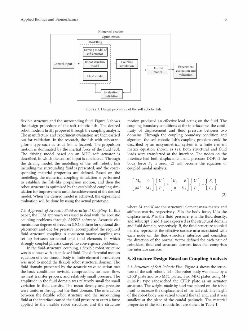
flexible structure and the surrounding fluid. Figure 3 showsthe design procedure of the soft robotic fish. The desiredrobot model is firstly proposed through the coupling analysis.The manufacture and experiment evaluation are then carriedout for validation. In the research, the fish with subcaran-giform type such as trout fish is focused. The propulsionmotion is dominated by the inertial force of the fluid [20].The driving model based on an MFC soft actuator isdescribed, in which the control input is considered. Throughthe driving model, the modelling of the soft robotic fishincluding the surrounding fluid is presented, and the corre-sponding material properties are defined. Based on themodelling, the numerical coupling simulation is performedto establish the fish-like propulsion motion, and then therobot structure is optimized by the established coupling sim-ulation for improvement until the achievement of the desiredmodel. When the desired model is achieved, the experimentevaluation will be done by using the actual prototype.
2.3. Approach of Acoustic Fluid-Structural Coupling. In thispaper, the FEM approach was used to deal with the acousticcoupling problems through ANSYS software. Acoustic ele-ments, four degrees of freedom (DOF): three for optional dis-placement and one for pressure, accomplished the requiredfluid-structural coupling. A consistent matrix coupling wasset up between structural and fluid elements in whichstrongly coupled physics caused no convergence problems.
In the fluid-structural coupling, a flexible robot structurewas in contact with an enclosed fluid. The differential motionequation of a continuum body in finite element formulationwas used to model the flexible robot structural domain. Thefluid domain presented by the acoustic wave equation metthe basic conditions: inviscid, compressible, no mean flow,no heat transfer process, and relatively small pressure. Theamplitude in the fluid domain was relatively small for smallvariation in fluid density. The mean density and pressurewere uniform throughout the fluid domain. The interactionbetween the flexible robot structure and the surroundingfluid at the interface caused the fluid pressure to exert a forceapplied to the flexible robot structure, and the structure
motion produced an effective load acting on the fluid. Thecoupling boundary conditions at the interface met the conti-nuity of displacement and fluid pressure between twodomains. Through the coupling boundary condition andalgorism, the soft robotic fish’s coupling problem could bedescribed by an unsymmetrical system in a finite elementmatrix equation shown as (2). Both structural and fluidloads were transferred at the interface. The nodes on theinterface had both displacement and pressure DOF. If thebody force FS is zero, (2) will become the equation ofcoupled modal analysis:
MS 0ρRT MF
U
P+
KS −R
0 KF
U
P=
FS
FF
,
2
where M and K are the structural element mass matrix andstiffness matrix, respectively, F is the body force, U is thedisplacement, P is the fluid pressure, ρ is the fluid density,and subscript S and F are expressed as the structural domainand fluid domain, respectively. R, the fluid-structure coupledmatrix, represents the effective surface area associated witheach node on the fluid-structure interface and considersthe direction of the normal vector defined for each pair ofcoincident fluid and structure element faces that comprisesthe interface surface.
3. Structure Design Based on Coupling Analysis
3.1. Structure of Soft Robotic Fish. Figure 4 shows the struc-ture of the soft robotic fish. The robot body was made by aCFRP plate and two MFC plates. Two MFC plates using M-8528-P1 type sandwiched the CFRP plate as an actuatorstructure. The weight made by steel was placed on the robothead to increase the displacement of the tail end. The heightof the robot body was varied toward the tail end, and it wassmallest at the place of the caudal peduncle. The materialproperties of the soft robotic fish are shown in Table 1.
Control input
Driving model ofso� actuator
Robot structuremodel
Fluid model
Couplingsimulation
Evaluation/validation
ModellingOptimization
Desiredmodel
Experimentevaluation and
validation
Numerical analysis
Figure 3: Design procedure of the soft robotic fish.
3Applied Bionics and Biomechanics
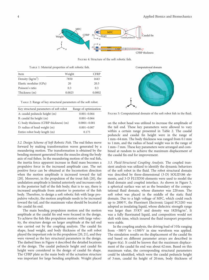
3.2. Design Scheme of Soft Robotic Fish. The real fishes moveforward by making transformation waves generated by ameandering motion. The transformation is obtained by thebending moment generated from the muscles along the bodyaxis of real fishes. In the meandering motion of the real fish,the inertia force apparent increase in fluid mass becomes apropulsive force in the increased amplitude case. The netpositive force can be obtained at the locomotion directionwhen the motion amplitude is increased toward the tail[20]. Moreover, in the propulsion of the trout fish [20], theundulation amplitude is limited anteriorly and increases onlyin the posterior half of the fish body; that is to say, there isincreased amplitude from anterior to posterior of the fishbody. Therefore, to design a soft robotic fish with large pro-pulsive velocity, the motion amplitude needs to be increasedtoward the tail, and the maximum value should be located atthe caudal fin end.
The main bending propulsion motion and the motionamplitude at the caudal fin end were focused in the design.To achieve the fish-like propulsion motion with large veloc-ity, the structure design on larger amplitude at the tail endwas carried out by the coupling analysis. The caudal finshape, head weight, and body thickness of the soft robotplayed the important role in the propulsion [20, 21], and theywere viewed as the key structural parameters in the design.The dashed lines in Figure 4 described the detailed locationsof the design. The caudal peduncle height and caudal finheight were considered in the design of caudal fin shape.The CFRP plate as the main body of the actuation structurewas important for large bending amplitude. Weight placed
on the robot head was utilized to increase the amplitude ofthe tail end. These key parameters were allowed to varywithin a certain range presented in Table 2. The caudalpeduncle and caudal fin height were in the range of1mm~64mm. The body thickness was ranged from 0.1mmto 1mm, and the radius of head weight was in the range of1mm~7mm. These key parameters were arranged and com-bined at random to achieve the maximum displacement ofthe caudal fin end for improvement.
3.3. Fluid-Structural Coupling Analysis. The coupled tran-sient analysis was utilized to identify the dynamic behaviorsof the soft robot in the fluid. The robot structural domainwas described by three-dimensional (3-D) SOLID186 ele-ments, and 3-D FLUID30 elements were used to model thefluid domain and coupled interface. As shown in Figure 5,a spherical surface was set as the boundary of the compu-tational fluid domain, whose diameter was 220mm. Thesoft robot was placed in the middle of the static fluiddomain. Due to a high voltage of MFC, which could reachup to 2000V, the Fluorinert Electronic Liquid FC3283 wasadopted as insulating liquid, whose dielectric strength rangewas larger than 35KV and density was 1820 kg/m3. Itwas a fully fluorinated liquid, and composition would notshift with time, which insured the fluid transport propertieswere stable.
In the coupling analysis, the driving load of 3Hz rangingfrom −500V to +1500V in sine waveform was applied.The simulation results on the displacement of the caudal finend based on different parameter arrays are described inFigure 6(a). It could be known that the maximum displace-ment of the caudal fin end was about 62mm. Based on thismaximum value, the corresponding structural parameterscould be identified, which were the caudal peduncle heightof 3mm, caudal fin height of 20mm, body thickness of
Table 1: Material properties of soft robotic fish.
Item Weight CFRP
Density (kg/m3) 7850 1643
Elastic modulus (GPa) 20 20.5
Poisson’s ratio 0.3 0.3
Thickness (m) 0.0025 0.0002
Table 2: Range of key structural parameters of the soft robot.
Key structural parameters of soft robot Range of optimization
A: caudal peduncle height (m) 0.001~0.064B: caudal fin height (m) 0.001~0.064C: body thickness (CFRP thickness) (m) 0.0001~0.001D: radius of head weight (m) 0.001~0.007Entire robot body length (m) 0.175
MFCMFC
Weight Weight
y
Y
XZ
y
zz
x
x
x
CFRPCaudal peduncle
Caudal fin
MFC CFRP
CFRP thicknessMFC
Figure 4: Structure of the soft robotic fish.
Computational domain
y
xz
Figure 5: Computational domain of the soft robot fish in the fluid.
4 Applied Bionics and Biomechanics

0.1mm, and radius of head weight of 7mm. A new robotmodel was therefore designed and is shown in Figure 6(b).
The bending mode frequencies of the new robot modelin the fluid are shown in Table 3, where the first three modeswere presented. The first bending mode frequency wasabout 2.5Hz, and its maximum deformation occurred atthe tail end. The second bending mode similar to S-shapewas obtained at about 9.5Hz. If the frequency was close to12Hz, the third bending mode occurred.
4. Experiment Evaluation
Figure 7 presents the prototype of the new soft robot. Thelow-density blowing agent as the float was placed on therobot head and top part to balance the robot weight in thefluid. The detailed specifications are shown in Table 4. The
epoxy 3M-DP460 was used to make the MFC and CFRPplates bond together.
Figure 8 presents the experiment platform and drivingsystem of the prototype. A cubical fluid tank filled withLiquid FC-3283 and a high-speed camera (Digital CameraEX-F1 from Casio Company) were utilized in the experi-ment. The main signal generation was controlled by a com-puter, and basic signal waveforms such as sine wave weredesigned. The signal processing circuit used a voltagefollower between a high-voltage amplifier (AMP PA05039)and a computer to reduce output impedance. The high-voltage amplifier was capable of delivering an output voltageof −500V to +1500V at an output current up to 50mA DC.The high-voltage output was controlled by the amplifierwhose input voltage was −2.5V~7.5V DC or peak AC corre-sponding to −500V~+1500V output. In the experiment, theinput voltage was ranged from −500V to +1500V and thefrequency was in the range of 1Hz~20Hz.
The bending mode frequencies of the prototype in thefluid are shown in Table 5. The main bending propulsionmode occurred at about 2Hz, and the second and third bend-ing modes generated at the frequency larger than 10Hz. Thesimulation results were validated by the experiment.
No. of parameter arraysA: 1-64 mmB: 1-64 mm
C: 0.1-1 mm
(A, B, C, D)(3,20,0.1,7)
D: 1-7 mm
0 10 20 30 40 50 60 70 80
0.07
0.06
0.05
0.04
0.03
0.02
0.01
0
Disp
lace
men
t (m
)
(a)
64 mm 20 mm3 mm14 mm
x
y
x
z
1.5 mm0.3 mm
0.1 mm
MFC
CFRP
Weight
(b)
Figure 6: Model of the soft robot. (a) Displacement of caudal fin end based on different parameter arrays. (b) New model of the soft robot.
Table 3: Bending mode frequencies of the new soft robot in thefluid.
Item Mode shape Frequency (Hz)
1st mode 2.5
2nd mode 9.5
3rd mode 11.8
Figure 7: Prototype of the new soft robotic fish.
Table 4: Specifications of the new soft robotic fish.
Item Specification
Caudal peduncle height (m) 0.003
Caudal fin height (m) 0.02
Radius of head weight (m) 0.007
Maximum body height (m) 0.064
Type of actuator MFC 8528P1× 2Actuator dimensions (m) 0.103× 0.035Actuator active area (m) 0.085× 0.028Actuator for adhering CFRP
Entire body length (m) 0.175
Adhesion bond Epoxy 3M-DP460
Weight (kg) 0.0141
5Applied Bionics and Biomechanics
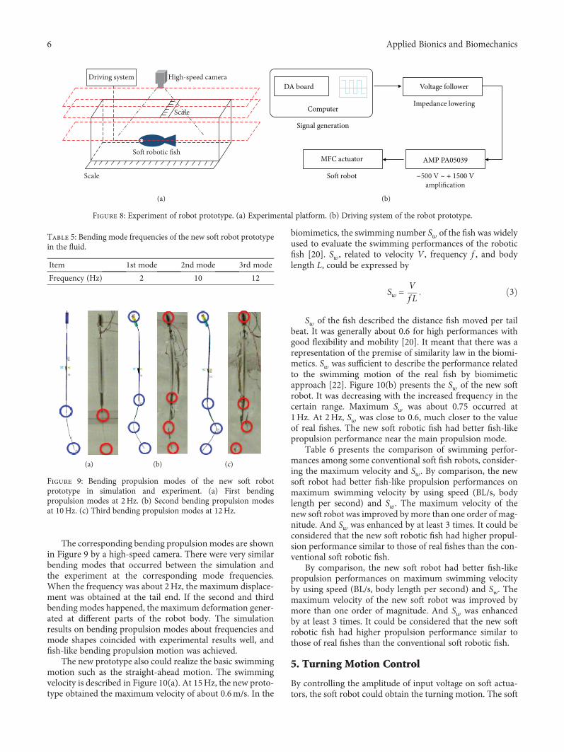
The corresponding bending propulsion modes are shownin Figure 9 by a high-speed camera. There were very similarbending modes that occurred between the simulation andthe experiment at the corresponding mode frequencies.When the frequency was about 2Hz, the maximum displace-ment was obtained at the tail end. If the second and thirdbending modes happened, the maximum deformation gener-ated at different parts of the robot body. The simulationresults on bending propulsion modes about frequencies andmode shapes coincided with experimental results well, andfish-like bending propulsion motion was achieved.
The new prototype also could realize the basic swimmingmotion such as the straight-ahead motion. The swimmingvelocity is described in Figure 10(a). At 15Hz, the new proto-type obtained the maximum velocity of about 0.6m/s. In the
biomimetics, the swimming number Sw of the fish was widelyused to evaluate the swimming performances of the roboticfish [20]. Sw, related to velocity V , frequency f , and bodylength L, could be expressed by
Sw = Vf L
3
Sw of the fish described the distance fish moved per tailbeat. It was generally about 0.6 for high performances withgood flexibility and mobility [20]. It meant that there was arepresentation of the premise of similarity law in the biomi-metics. Sw was sufficient to describe the performance relatedto the swimming motion of the real fish by biomimeticapproach [22]. Figure 10(b) presents the Sw of the new softrobot. It was decreasing with the increased frequency in thecertain range. Maximum Sw was about 0.75 occurred at1Hz. At 2Hz, Sw was close to 0.6, much closer to the valueof real fishes. The new soft robotic fish had better fish-likepropulsion performance near the main propulsion mode.
Table 6 presents the comparison of swimming perfor-mances among some conventional soft fish robots, consider-ing the maximum velocity and Sw. By comparison, the newsoft robot had better fish-like propulsion performances onmaximum swimming velocity by using speed (BL/s, bodylength per second) and Sw. The maximum velocity of thenew soft robot was improved bymore than one order of mag-nitude. And Sw was enhanced by at least 3 times. It could beconsidered that the new soft robotic fish had higher propul-sion performance similar to those of real fishes than the con-ventional soft robotic fish.
By comparison, the new soft robot had better fish-likepropulsion performances on maximum swimming velocityby using speed (BL/s, body length per second) and Sw. Themaximum velocity of the new soft robot was improved bymore than one order of magnitude. And Sw was enhancedby at least 3 times. It could be considered that the new softrobotic fish had higher propulsion performance similar tothose of real fishes than the conventional soft robotic fish.
5. Turning Motion Control
By controlling the amplitude of input voltage on soft actua-tors, the soft robot could obtain the turning motion. The soft
High-speed camera
So� robotic fish
Scale
Scale
Driving system
(a)
DA board
Computer
Signal generation
Voltage follower
Impedance lowering
AMP PA05039MFC actuator
So� robot −500 V ~ + 1500 Vamplification
(b)
Figure 8: Experiment of robot prototype. (a) Experimental platform. (b) Driving system of the robot prototype.
Table 5: Bending mode frequencies of the new soft robot prototypein the fluid.
Item 1st mode 2nd mode 3rd mode
Frequency (Hz) 2 10 12
(a) (b) (c)
Figure 9: Bending propulsion modes of the new soft robotprototype in simulation and experiment. (a) First bendingpropulsion modes at 2Hz. (b) Second bending propulsion modesat 10Hz. (c) Third bending propulsion modes at 12Hz.
6 Applied Bionics and Biomechanics

robot in [6] was taken as an example to describe in this part.The input voltage of 3Hz ranging from −500V to +1500V insine and square waveform was applied on this soft robot.
In the research, the soft robotic fish was composed of twosoft actuators for propulsion. When the input voltage signals
on both left and right MFC actuators had the same voltageamplitude and were distributed in opposite directionsfrom each other, the straight-ahead motion was realizedon the soft robotic fish. Figure 11 describes the input volt-ages in sine and square waveform on both left and right
0 5 10 15 200.0
0.2
0.4
0.6
0.8V
eloc
ity (m
/s)
Frequency (Hz)
(a)
0 5 10 15 200.0
0.2
0.4
0.6
0.8
1.0
Sw
Frequency (Hz)
(b)
Figure 10: Swimming performance of the new soft robotic fish. (a) Swimming velocity at different frequencies. (b) Swimming number atdifferent frequencies.
Table 6: Comparison of swimming performance of the conventional soft robotic fish.
Soft robotic fish Soft actuator Maximum Sw Maximum speed (BL/s)
Kagawa University ICPF 0.09 0.16
Polytechnic University of Madrid SMA 0.2 0.1
Tokyo University Electrostatic film 0.083 0.14
Michigan State University IPMC 0.044 0.04848
This study PFC 0.75 3.5
0.0 0.2 0.4 0.6 0.8 1.0 1.2 1.4 1.6 1.8
−500
0
500
1000
1500
Le�Right
Time (s)
Volta
ge (N
)
(a)
0.0 0.2 0.4 0.6 0.8 1.0 1.2 1.4 1.6 1.8
−500
0
500
1000
1500
Le�Right
Time (s)
Volta
ge (N
)
(b)
Figure 11: Waveforms on both MFC actuators at 3Hz in straight-ahead motion. (a) Input voltages in sine waveform. (b) Input voltages insquare waveform.
7Applied Bionics and Biomechanics

MFC actuators for straight-ahead motion of the soft roboticfish. The input voltages on both actuators are all in therange of −500V~+1500V, and they were applied on the softrobotic fish in the opposite directions.
Based on these input voltage signals on both MFC actua-tors, the straight-ahead motion of the soft robotic fish wasgenerated and the corresponding propulsion modes are pre-sented in Figure 12. In Figure 12, the positive displacementdescribed the displacement on the left side of the swing.Otherwise, it described the right-side displacement of theswing. The swing of the caudal fin in straight-ahead motionwas in symmetrical distribution around the midline of thesoft robotic fish in both sine and square waveform. Throughcharacterizing this propulsion mode, the straight-aheadmotion was realized. Besides, the swing displacement at the
tail end in square waveform was larger. This was becausethe square waveform not only considered fundamental fre-quency component but also contained harmonics of funda-mental frequency. It was possible that the soft robot hadthe faster swimming velocity by using the square waveform.
In order to realize the turning motion of the soft roboticfish, the asymmetric signals were applied based on the condi-tions of the straight-ahead motion. Through controllinginput voltage signals for bias voltage between two soft actu-ators, the turning motion could be obtained due to theasymmetrical output from actuators. When the voltageamplitude on the left actuator was larger, the motion ofturning right was obtained. On the contrary, the motion ofturning left occurred. Figure 13 presents the input voltageson both actuators in the motion of turning right. The input
0.00 0.03 0.06 0.09 0.12 0.15 0.18−0.03
−0.02
−0.01
0.00
0.01
0.02
0.03D
ispla
cem
ent (
m)
Body length (m)
(a)
0.00 0.03 0.06 0.09 0.12 0.15 0.18−0.04
−0.03
−0.02
−0.01
0.00
0.01
0.02
0.03
0.04
Disp
lace
men
t (m
)
Body length (m)
(b)
Figure 12: Propulsion modes of the soft robotic fish in one cycle at 3Hz in straight-ahead motion. (a) Results in sine waveform. (b) Results insquare waveform.
0.0 0.2 0.4 0.6 0.8 1.0 1.2 1.4 1.6 1.8
−500
0
500
1000
1500
Le�Right
Time (s)
Vol
tage
(V)
(a)
Le�Right
0.0 0.2 0.4 0.6 0.8 1.0 1.2 1.4 1.6 1.8
−500
0
500
1000
1500
Time (s)
Vol
tage
(V)
(b)
Figure 13: Waveforms on both MFC actuators at 3Hz in the motion of turning right. (a) Input voltages in sine waveform. (b) Input voltagesin square waveform.
8 Applied Bionics and Biomechanics

voltage on the left actuator was in the range of −500V~+1500V, larger than the voltage ranged from −500V to+500V on the right actuator.
Based on these asymmetrical signals, the motion of turn-ing right was achieved and corresponding propulsion modesare described in Figure 14. The swing of the caudal fin wasasymmetrical around the midline of the soft robotic fish inboth sine and square waveform. In Figure 14, the positivedisplacement described the displacement on the left side ofthe swing. Otherwise, it described the right-side displace-ment of the swing. The swing of the caudal fin mainlyoccurred on the right side of the soft robot, and the turningright motion thus generated. Besides, the swing displacementat the tail end in sine waveform was smaller than the resultsof square waveform due to the representation of only funda-mental frequency in sine waveform.
For the motion of turning left, the applied approachof input voltages was contrary to that of turning rightmotion. The voltage on the left actuator was in the range of−500V~+500V, and the voltage on the right actuator wasranged from −500V to +1500V. Based on these asymmet-rical input voltages, the turning left motion was achievedand the corresponding propulsion modes are presented inFigure 15. The displacement on the left side of the swingwas larger. It could also be found that the displacement atthe tail end in sine waveform was smaller.
Based on the controllability of input signals, swimmingmotions such as turning motion could be achieved. To val-idate the turning motion control of the soft robot, the cor-responding experiments on robot prototype in [10] wereperformed. The experimental platform on the measurementof the turning motion by a high-speed camera is described
0.00 0.03 0.06 0.09 0.12 0.15 0.18−0.03
−0.02
−0.01
0.00
0.01
0.02
0.03D
ispla
cem
ent (
m)
Body length (m)
(a)
0.00 0.03 0.06 0.09 0.12 0.15 0.18−0.04
−0.03
−0.02
−0.01
0.00
0.01
0.02
0.03
0.04
Disp
lace
men
t (m
)
Body length (m)
(b)
Figure 14: Propulsionmodes of soft robotic fish in one cycle at 3Hz in the motion of turning right. (a) Results in sine waveform. (b) Results insquare waveform.
0.00 0.03 0.06 0.09 0.12 0.15 0.18−0.03
−0.02
−0.01
0.00
0.01
0.02
0.03
Disp
lace
men
t (m
)
Body length (m)
(a)
0.00 0.03 0.06 0.09 0.12 0.15 0.18−0.04
−0.03
−0.02
−0.01
0.00
0.01
0.02
0.03
0.04
Disp
lace
men
t (m
)
Body length (m)
(b)
Figure 15: Propulsion modes of soft robotic fish in one cycle at 3Hz in the motion of turning left. (a) Results in sine waveform. (b) Results insquare waveform.
9Applied Bionics and Biomechanics
0.0 0.1 0.2 0.3 0.4 0.5
−500
0
500
1000
1500
Le�Right
Time (s)
Vol
tage
(V)
(a)
Le�Right
0.0 0.1 0.2 0.3 0.4 0.5
−500
0
500
1000
1500
Time (s)
Vol
tage
(V)
(b)
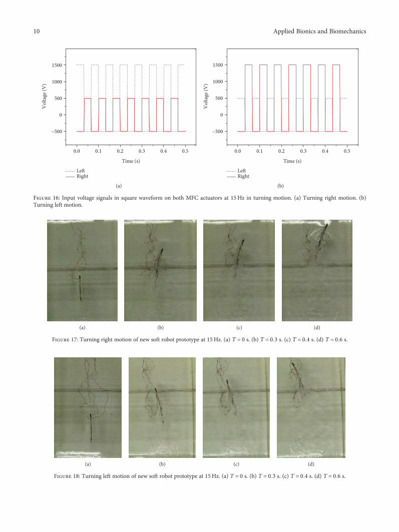
Figure 16: Input voltage signals in square waveform on both MFC actuators at 15Hz in turning motion. (a) Turning right motion. (b)Turning left motion.
(a) (b) (c) (d)
Figure 17: Turning right motion of new soft robot prototype at 15Hz. (a) T = 0 s. (b) T = 0 3 s. (c) T = 0 4 s. (d) T = 0 6 s.
(a) (b) (c) (d)
Figure 18: Turning left motion of new soft robot prototype at 15Hz. (a) T = 0 s. (b) T = 0 3 s. (c) T = 0 4 s. (d) T = 0 6 s.
10 Applied Bionics and Biomechanics

in Figure 8. The high-speed camera was placed on the topof the fluid tank. The turning velocity of the soft robotcould be predicted by photographing the turning motionvideo. Due to the achievement of larger velocity by usingsquare waveform in robot actuation, the input voltages insquare waveform were applied on the prototype to describethe turning motion.
Through applying the asymmetrical signals on both actu-ators, motions of turning right and turning left were achievedsuccessfully. Based on the trajectory of turning motion andcorresponding time, the turning velocity was determined,and the maximum turning velocity was about 27 deg/s byusing square waveform.
According to the control method of input voltage signalson both actuators, the turning motion was also achieved onthe new soft robot prototype. To describe the turning motionof the new soft robot, the input voltage signals with 15Hz insquare waveform shown in Figure 16 were adopted, wherethe signals within 0.5 s were used as an example for descrip-tion. In turning right motion, the input voltage on the rightactuator was in the range of −500V~+500V, smaller thanthe voltage ranged from −500V to +1500V on the left actu-ator. For the turning left motion, the applied approach ofinput voltage signals on both actuators was contrary to thatof turning right motion.
Based on these asymmetrical input voltage signals, theturning motions of the new soft robotic fish were achieved.Figures 17 and 18 present the turning right motion and turn-ing left motion of the new soft robot prototype at its maxi-mum swimming velocity by using a high-speed camera,respectively. Based on the trajectory of turning motion andcorresponding time, the turning velocity was determined.The turning right motion with about 51.6 deg/s and turningleft motion with about 53 deg/s were obtained at 15Hz. Awell-established experiment on a new soft robot prototypealso validated the turning motion control.
6. Conclusions
In this paper, a new soft robotic fish using PFC was designedthrough the fluid-structural coupling analysis based on bio-mimetic approach. Through the experiment evaluation, itwas confirmed that the better fish-like swimming perfor-mances were achieved successfully by the new soft roboticfish. The new soft robotic fish with high performance similarto those of real fishes had been developed successfully. Inaddition, the turning motion control of the soft robotic fishwas established by controlling the input signals on both actu-ators. The turning left motion about 53 deg/s and turningright motion about 51.6 deg/s were achieved through thenew soft robotic fish at the place where the maximum swim-ming velocity occurred.
Data Availability
The data used to support the findings of this study are avail-able from the corresponding author upon request.
Conflicts of Interest
The authors declare that there is no conflict of interestregarding the publication of this paper.
Acknowledgments
The work reported in this paper was supported by theNational Natural Science Foundation of China (51605436)and the Natural Science Foundation of Zhejiang Provinceof China (LQ16E050009).
References
[1] E. J. Kim and Y. Youm, “Design and dynamic analysis of fishrobot: Potuna,” in Proceedings of the IEEE Int. Conf. on Robot-ics and Automation, pp. 4887–4892, New Orleans, LA, USA,2004.
[2] J. M. Anderson, “The vorticity control unmanned underseavehicle-an autonomous robot tuna,” in Proceedings of Associa-tion for Unmanned Vehicle System International, pp. 663–668,Huntsville, AL, USA, 1998.
[3] K. H. Low, C. W. Chong, and C. L. Zhou, “Performance studyof a fish robot propelled by a flexible caudal fin,” in 2010 IEEEInternational Conference on Robotics and Automation, pp. 90–95, Anchorage, AK, USA, 2010.
[4] A. Crespi, A. Badertscher, A. Guignard, and A. J. Ijspeert,“AmphiBot I: an amphibious snake-like robot,” Robotics andAutonomous Systems, vol. 50, no. 4, pp. 163–175, 2005.
[5] M. Mojarrad andM. Shahinpoor, “Biomimetic robotic propul-sion using polymeric artificial muscles,” in Proceedings ofInternational Conference on Robotics and Automation,pp. 2152–2157, Albuquerque, New Mexico, 1997.
[6] W. Zhao, J. Shintake, A. Ming, and M. Shimojo, “Structuraldesign and dynamic analysis of robotic fish with piezoelectricfiber composite,” in 2012 9th France-Japan & 7th Europe-Asia Congress on Mechatronics (MECATRONICS) / 13th Int'lWorkshop on Research and Education in Mechatronics(REM), pp. 161–168, Paris, France, 2012.
[7] W. Zhao, A. Ming, and M. Shimojo, “Dynamic analysis andoptimization of soft robotic fish using fluid-structural couplingmethod,” in 2014 IEEE International Conference on Roboticsand Automation (ICRA), pp. 1474–1479, Hong Kong, 2014.
[8] D. Trivedi, C. D. Rahn, W. M. Kier, and I. D. Walker, “Softrobotics: biological inspiration, state of the art, and futureresearch,” Applied Bionics and Biomechanics, vol. 5, no. 3,117 pages, 2008.
[9] H. Liu, Y. Tang, Q. Zhu, and G. Xie, “Present research situa-tions and future prospects on biomimetic robot fish,” Interna-tional Journal on Smart Sensing and Intelligent Systems, vol. 7,no. 2, pp. 458–480, 2014.
[10] A. D. Marchese, C. D. Onal, and D. Rus, “Autonomous softrobotic fish capable of escape maneuvers using fluidic elasto-mer actuators,” Soft Robotics, vol. 1, no. 1, pp. 75–87, 2014.
[11] Z. Zhang, N. Yamashita, and M. Gondo, “Electrostaticallyactuated robotic fish: design and control for high-mobilityopen-loop swimming,” IEEE Transactions on Robotics,vol. 24, no. 1, pp. 118–129, 2008.
[12] A. Suleman and C. Crawford, “Design and testing of a biomi-metic tuna using shape memory alloy induced propulsion,”Computers & Structures, vol. 86, no. 3–5, pp. 491–499, 2008.
11Applied Bionics and Biomechanics
[13] S. Kim, C. Laschi, and B. Trimmer, “Soft robotics: a bioin-spired evolution in robotics,” Trends Biotechnology, vol. 31,no. 5, pp. 287–294, 2013.
[14] S. Ai and L. Sun, “Fluid-structure coupled analysis of underwa-ter cylindrical shells,” Journal of Marine Science and Applica-tion, vol. 7, no. 2, pp. 77–81, 2008.
[15] S. Sung and D. J. Nefske, “A coupled structural-acousticfinite element model for vehicle interior noise analysis,” Jour-nal of Vibration, Acoustics, Stress, and Reliability in Design,vol. 106, no. 2, pp. 314–318, 1984.
[16] H. Djojodihardjo and I. Safari, “BEM-FEM acoustic-structureinteraction for modeling and analysis of spacecraft structuressubject to acoustic excitation,” in 2007 3rd International Con-ference on Recent Advances in Space Technologies, pp. 165–170,Istanbul, 2007.
[17] R. B. Williams, G. Park, D. J. Inman, and W. K. Wilkie, “Anoverview of composite actuators with piezoceramic fibers,” in20th International Modal Analysis Conference, pp. 421–427,Los Angeles, CA, USA, 2002.
[18] R. B. Williams, Nonlinear mechanical and actuation character-ization of piezoceramic fiber composites, [Ph.D. thesis], VirginiaPolytechnic Institute and State University, USA, 2004.
[19] A. C. Price, C. J. Weadick, J. Shim, and F. H. Rodd, “Pigments,patterns, and fish behavior,” Zebrafish, vol. 5, no. 4, pp. 297–307, 2008.
[20] A. Azuma, Encyclopaedia of Creature’s Motion, Asakura Pub-lishing, Asakura, 1997.
[21] H. Kagemoto, D. K. P. Yue, and M. S. Triantafyllou, “Why dofish have the ‘fish-like geometry?’,” in Proceedings of theAnnual Meeting, Japan Society of Fluid Mechanics, vol. 29,pp. 395-396, 2010.
[22] I. Tanaka and M. Nagai, Hydrodynamic of Resistance andPropulsion-Learn from the Fast Swimming Ability of AquaticAnimals, Ship & Ocean Foundation, 1996.
12 Applied Bionics and Biomechanics

International Journal of
AerospaceEngineeringHindawiwww.hindawi.com Volume 2018
RoboticsJournal of
Hindawiwww.hindawi.com Volume 2018
Hindawiwww.hindawi.com Volume 2018
Active and Passive Electronic Components
VLSI Design
Hindawiwww.hindawi.com Volume 2018
Hindawiwww.hindawi.com Volume 2018
Shock and Vibration
Hindawiwww.hindawi.com Volume 2018
Civil EngineeringAdvances in
Acoustics and VibrationAdvances in
Hindawiwww.hindawi.com Volume 2018
Hindawiwww.hindawi.com Volume 2018
Electrical and Computer Engineering
Journal of
Advances inOptoElectronics
Hindawiwww.hindawi.com
Volume 2018
Hindawi Publishing Corporation http://www.hindawi.com Volume 2013Hindawiwww.hindawi.com
The Scientific World Journal
Volume 2018
Control Scienceand Engineering
Journal of
Hindawiwww.hindawi.com Volume 2018
Hindawiwww.hindawi.com
Journal ofEngineeringVolume 2018
SensorsJournal of
Hindawiwww.hindawi.com Volume 2018
International Journal of
RotatingMachinery
Hindawiwww.hindawi.com Volume 2018
Modelling &Simulationin EngineeringHindawiwww.hindawi.com Volume 2018
Hindawiwww.hindawi.com Volume 2018
Chemical EngineeringInternational Journal of Antennas and
Propagation
International Journal of
Hindawiwww.hindawi.com Volume 2018
Hindawiwww.hindawi.com Volume 2018
Navigation and Observation
International Journal of
Hindawi
www.hindawi.com Volume 2018
Advances in
Multimedia
Submit your manuscripts atwww.hindawi.com