development of design tool for nigerian (cbr) design of flexible pavement · development of design...
TRANSCRIPT
www.scholarsresearchlibrary.comtAvailable online a
Scholars Research Library
Archives of Applied Science Research, 2015, 7 (10):1-16
(http://scholarsresearchlibrary.com/archive.html)
ISSN 0975-508X
CODEN (USA) AASRC9
1 Scholars Research Library
Development of design tool for Nigerian (CBR) design of flexible pavement
Ekwulo E. O and Bresford J.
Civil Engineering Department, Rivers State University of Science and Technology, Port Harcourt, Rivers State, Nigeria
_____________________________________________________________________________________________ ABSTRACT As a result of the inconsistencies in the result of structural thickness design of flexible pavements, arising from individual differences in sight and judgment in the use of design charts and tables, a study on the development of a computer program for the design of flexible pavement was carried out. The study was based on the Nigerian (CBR) design method for flexible pavement. The thickness above layer for each pavement material was obtained by interpolation at 1% CBR interval. Using the data obtained, equations for curves A to F were developed. Using the developed equations, Algorithm and codes were written in accordance with the Nigerian (CBR) designs procedure. The results of developed program, N-Flex-Pave were validated by comparing it results with that of the conventional procedure (CBR design curve). Results show that structural thickness design using N-Flex-Pave compared favorably with the conventional procedure with a minimum ratio of 0.97 and a maximum ratio of 1.10. Calibration of N-Flex-Pave-calculated and Design Curve-measured results were compared using linear regression analysis and the results were found to be good with minimum coefficient of determination R2 of 0.996 and maximum R2 of 0.999 indicating that N-Flex-Pave is a good estimator of pavement layer thickness using the Nigerian (CBR) design procedure. Result also indicated that design can be completed in few seconds when compared to the time spent when conventional procedures are employed. A conclusion was made that N-Flex-Pave is capable of carrying out structural thickness design for the Nigerian (CBR) method and should be recommended for use by pavement engineers in Nigeria. Key words: Computer Program, CBR, Flexible Pavement, Design. _____________________________________________________________________________________________
INTRODUCTION
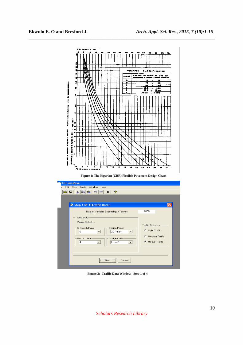
In Nigeria, the only developed and most common method of flexible pavement design is the Nigerian (CBR) method. In this method, the determination of structural thickness of the pavement is made using design charts and Tables. In most cases, no two individual obtains the same result even when the same design information is used. The Nigerian (CBR) method is an empirical procedure which uses the California Bearing Ratio and traffic volume as the sole design inputs. The method was originally developed by the U.S Corps of Engineers, modified by the British Road Research Laboratory [1] and adopted by Nigeria as contained in the Federal Highway Manual [2]. The Nigerian (CBR) design method is a CBR-Traffic volume method, the thickness of the pavement structure is dependent on the anticipated traffic, the strength of the foundation material, the quality of pavement material used and the construction procedure adopted. The method considers traffic in the form of number of commercial vehicles/day exceeding 29.89kN (3 tons). To determine the no of vehicles/day exceeding 3 tons loaded weight, the anticipated traffic is adjusted using the traffic adjustment factor in Table 1 and percentage of trucks in the design
Ekwulo E. O and Bresford J. Arch. Appl. Sci. Res., 2015, 7 (10):1-16 ______________________________________________________________________________
2 Scholars Research Library
lawne in Table 2. The selection of pavement structure is made from design curves as shown in Figure 1. The thickness of the pavement layers is dependent on the expected traffic loading. The recommended minimum asphalt pavement surface thickness is considered in terms of light, medium and heavy traffic as follows: Light traffic - 50mm Medium - 75mm Heavy - 100mm The inconsistencies and variations in the result of structural thickness design of pavements arising from individual differences in sight and judgment in the use of design charts and tables have become a matter of concern for pavement designers. Hence, the need to develop a more precise and accurate design tool that will enable pavement designers produce uniform structural thickness design results. There is no existing computer program for the design of flexible pavement for the Nigerian (CBR) design method. The purpose of this paper is to develop the design tool, N-Flex-Pave, for the Nigerian (CBR) design of flexible pavement. This will ease design process and provide a uniform flexible pavement structural design result using the Nigerian (CBR) procedure. Prior to the invention of the computers, pavement designs were solely carried out using design charts, Tables and nomographs. In contemporary times with the invention of computers, pavement design could be carried out using computer programs. Several computer programs have been developed for the design of pavements. The programs are either empirical, layered elastic analysis or finite element programs. The American Association of State Highway and Transportation Official AASHTO [3] developed its empirical design utility for flexible and rigid pavement. The program solves the 1993 AASHTO Guide basic empirical design equation for flexible and Rigid pavements. It also provides information on variable descriptions, typical values and equation precautions. A number of computer programs based on layered elastic theory [4] have been developed for layered elastic analysis. The program CHEV [5] developed by the Chevron Research Company can be applied to linear materials, however, CHEV program was modified to account for material non-linearity and called DAMA [6]. The DAMA computer program can be used to analyze a multi-layered elastic pavement structure under single or dual-wheel load, the number of layers cannot exceed five. In DAMA, the subgrade and the asphalt layers are considered to be linearly elastic and the untreated subbase to be non-linear. Instead of using iterative method to determine the modulus of granular layer, the effect of stress dependency is included by effective elastic modulus computed according to equation 1.0. E2 = 10.447h1
-0.471h2-0.041E1
-0.139E3-0.287K1
0.868 (1.0) Where, E1, E2 and E3 are the modulus of asphalt layer, granular base and subgrade respectively; h1 and h2 are the thicknesses of the asphalt layer and granular base. K1 and K2 are parameters for K-θ model with k2 = 0.5. ELSYM5 developed at the University of California is a five layer linear elastic program for the determination of stresses and strains in pavements [7; 8]. The KENLAYER computer program developed at the University of Kentucky in 1985 incorporates the solution for an elastic multiple-layered system under a circular load. KENLAYER can be applied to layered system under single, dual, dual-tandem wheel loads with each layer material properties being linearly elastic, non-linearly elastic or visco-elastic. The Everstress [9] layered elastic analysis program from the Washington State Department of Transportation was developed from WESLEA layered elastic analysis program. The pavement system model is multilayered elastic using multiple wheel loads (up to 20). The program can analyze hot mix asphalt (HMA) pavement structure containing up to five layers and can consider the stress sensitive characteristics of unbound pavement materials. The consideration of the stress sensitive characteristics of unbound materials can be achieved through adjusting the layer moduli in an iterative manner by use of stress-modulus relationships in equations 2.0 and 3.0; Eb = K1θK2 for granular soils (2.0) Eb = K3σdK4 for fine grained soils (3.0) Where, Eb = Resilient modulus of granualar soils (ksi or MPa)
Ekwulo E. O and Bresford J. Arch. Appl. Sci. Res., 2015, 7 (10):1-16 ______________________________________________________________________________
3 Scholars Research Library
Es = Resilient modulus of fine grained soils (ksi or MPa) θ = Bulk stress (ksi or MPa) σd = (Deviator stress (ksi or Mpa) and K1, K2, K3, K4 = Regression constants K1, and K2, are dependent on moisture content, which can change with the seasons. K3, and K4 are related to the soil types, either coarse grained or fine-grained soil. K2 is positive and K4 is negative and remain relatively constant with the season. The ILLI_PAVE 2D computer program (10) developed at the University of Illinois at Urbana-Champaign treats the pavement system as an axi-symmetric solid domain. The resilient modulus is stress-dependent and failure criteria for granular material and fine-grained soils are incorporated in ILLI_PAVE. The principal stresses in the subbase and subgrade layers are updated iteratively. The Mohr-Coulomb theory is employed as a criterion to ensure the principal stresses do not exceed the strength of the material. When the base or subgrade layer is divided into several layers, the minor stresses in the upper layer may be very small or become tensile in the lower layers. Therefore, the replacement of the small or negative stress by a large positive stress results in a higher, modulus. The MICH_PAVE 2D [11] finite element computer program is very similar to ILLI_PAVE. It uses the same methods to model granular material and soils and the same Mohr-Coulomb failure criteria. MICH_PAVE uses a flexible boundary at a limited depth beneath the surface of subgrade instead of a rigid boundary at a large depth below the surface. MICH_PAVE is capable of performing both linear and non-linear finite element analysis of flexible pavements. It assumes axi-symmetric loading condition and computes an equivalent resilient modulus for each pavement layer that is obtained as the average of the moduli of the finite elements in the layer that lie within an assumed 2:1 load distribution zone. For non-linear material, MICH_PAVE employs the stress dependent K-θ model to characterize the resilient modulus of soils through a stress dependent modulus and constant Poisson’s ratio. ABAQUS, a commercially available 3D FE program has been used in the structural analysis of pavement systems. The program has the ability to accommodate both 2D FE analysis and 3D FE analysis and use reduced integration elements (3D) to reduce the total computational time [12].
MATERIALS AND METHODS
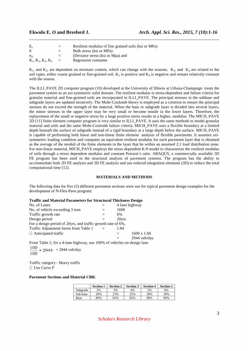
The following data for five (5) different pavement sections were use for typical pavement design examples for the development of N-Flex-Pave program: Traffic and Material Parameters for Structural Thic kness Design No. of Lanes = 4 lane highway No. of vehicle exceeding 3 tons = 1600 Traffic growth rate = 6% Design period = 20yrs For a design period of 20yrs, and traffic growth rate of 6%, Traffic Adjustment factor from Table 1 = 1.84 ∴ Anticipated traffic = 1600 x 1.84 = 2944 veh/day From Table 2, for a 4-lane highway, use 100% of vehicles on design lane
2944100
100 × = 2944 veh/day
Traffic category - Heavy traffic ∴ Use Curve F Pavement Sections and Material CBR:
Section 1 Section 2 Section 3 Section 4 Section 5 Subgrade 2% 3% 4% 5% 6% Sub-base 20% 23% 25% 28% 30% Base 80% 83% 85% 88% 90%
Ekwulo E. O and Bresford J. Arch. Appl. Sci. Res., 2015, 7 (10):1-16 ______________________________________________________________________________
4 Scholars Research Library
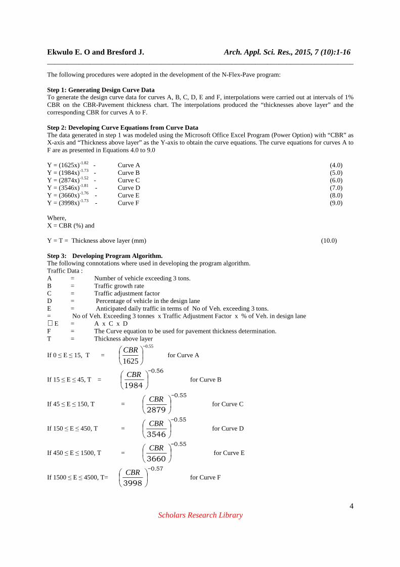
The following procedures were adopted in the development of the N-Flex-Pave program: Step 1: Generating Design Curve Data To generate the design curve data for curves A, B, C, D, E and F, interpolations were carried out at intervals of 1% CBR on the CBR-Pavement thickness chart. The interpolations produced the “thicknesses above layer” and the corresponding CBR for curves A to F. Step 2: Developing Curve Equations from Curve Data The data generated in step 1 was modeled using the Microsoft Office Excel Program (Power Option) with “CBR” as X-axis and “Thickness above layer” as the Y-axis to obtain the curve equations. The curve equations for curves A to F are as presented in Equations 4.0 to 9.0 Y = (1625x)-1.82 - Curve A (4.0) Y = (1984x)-1.73 - Curve B (5.0) Y = (2874x)-1.52 - Curve C (6.0) Y = (3546x)-1.81 - Curve D (7.0) Y = (3660x)-1.76 - Curve E (8.0) Y = (3998x)-1.73 - Curve F (9.0) Where, X = CBR (%) and Y = T = Thickness above layer (mm) (10.0) Step 3: Developing Program Algorithm. The following connotations where used in developing the program algorithm. Traffic Data : A = Number of vehicle exceeding 3 tons. B = Traffic growth rate C = Traffic adjustment factor D = Percentage of vehicle in the design lane E = Anticipated daily traffic in terms of No of Veh. exceeding 3 tons. = No of Veh. Exceeding 3 tonnes x Traffic Adjustment Factor x % of Veh. in design lane ∴E = A x C x D F = The Curve equation to be used for pavement thickness determination. T = Thickness above layer
If 0 ≤ E ≤ 15, T =
55.0
1625
−
CBR for Curve A
If 15 ≤ E ≤ 45, T = 560
1984
.−
CBR for Curve B
If 45 ≤ E ≤ 150, T = 550
2879
.−
CBR for Curve C
If 150 ≤ E ≤ 450, T = 550
3546
.−
CBR for Curve D
If 450 ≤ E ≤ 1500, T = 550
3660
.−
CBR for Curve E
If 1500 ≤ E ≤ 4500, T= 570
3998
.−
CBR for Curve F

Ekwulo E. O and Bresford J. Arch. Appl. Sci. Res., 2015, 7 (10):1-16 ______________________________________________________________________________
5 Scholars Research Library
Thickness Description: T1 = Total thickness T2 = Thickness of base and surface T3 = Thickness of surface = Tsurface T2 – T3 = Thickness of base = Tbase
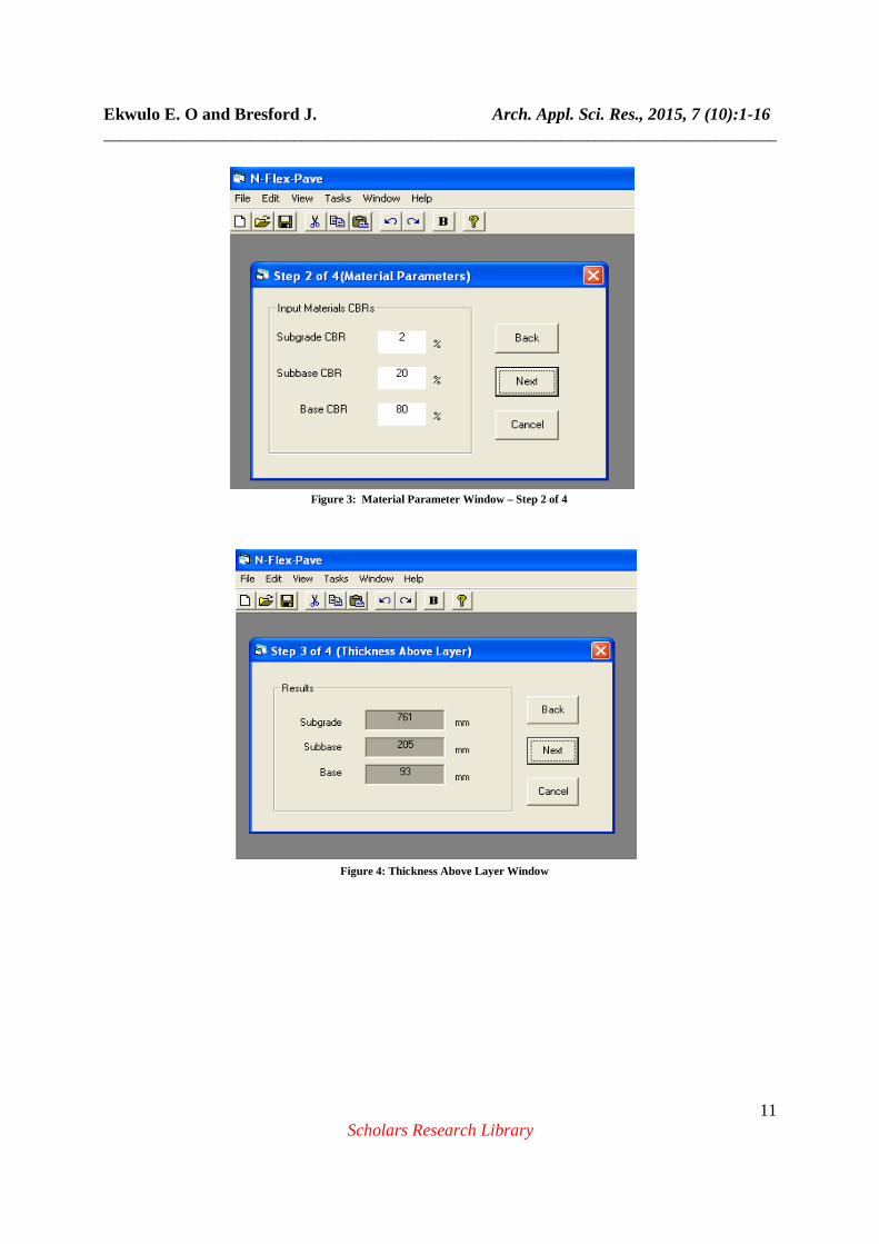
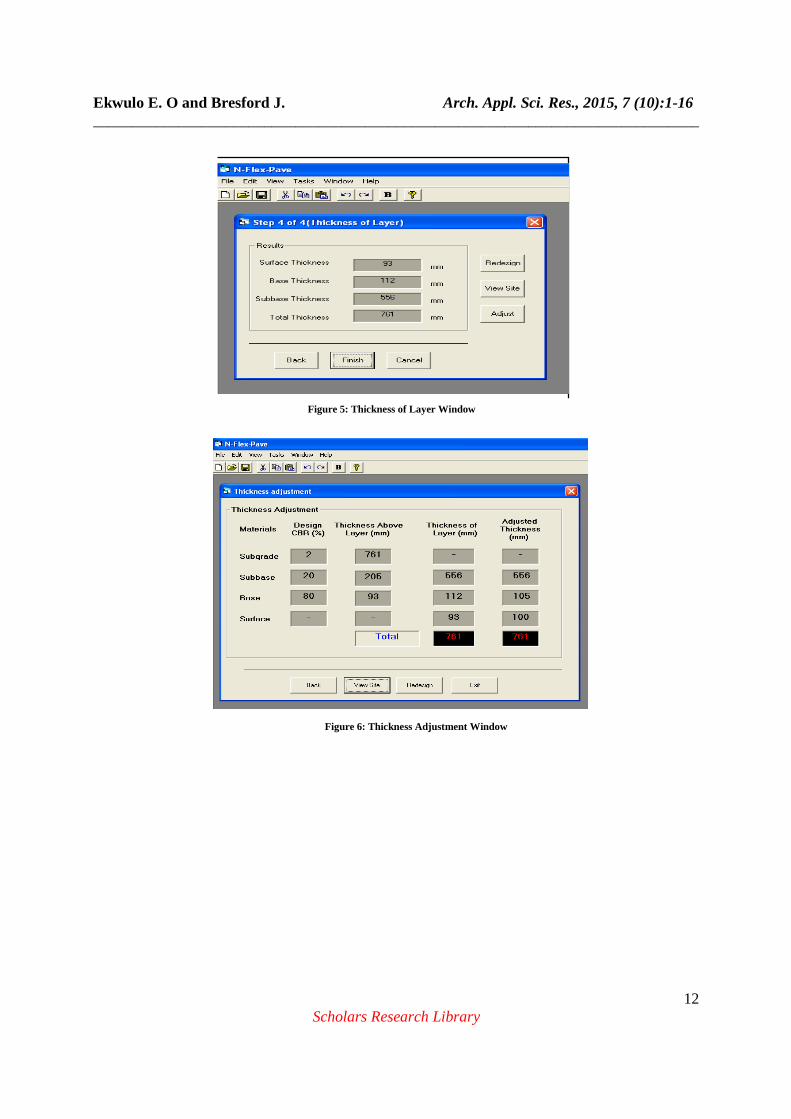
T1 – T2 = Thickness of sub-base = Tsubbase Recommended Thickness of Surface: Light traffic; T3 ≥ 50 Medium traffic; T3 ≥ 75 Heavy traffic; T3 ≥ 100 Step 4: Creating Interface on Visual Basic Package a) Creating Textbox: Pick text box on the tool box, set property name; b) Creating Label: Pick label on the toolbox, click caption then reset the name property. c) Set board style d) Insert name property e) Name property: This is where the calculated output is being displayed f) Pick command button, go to caption and type in text calculate, then go to name property and say cmd calc. g) Form addition: go to project and say add form. Step 5: Code Writing The codes were written in Visual basic 6.0 [13]. The following codes were written in line with the program algorithm; i. Codes to Determine Traffic Parameters ii. Codes to evaluate the various thicknesses iii. Codes for thickness adjustment iv. Codes for the cross section of the designed pavement Executing the N-Flex-Pave Program The N-Flex-Pave is a user-friendly program, it is simple to use and easy to run. The program is applicable to four-layered (Surface, base, subbase and subgrade) flexible pavement system. When all the necessary design input parameters have been made, the program can run successfully in less than 30 seconds. The following traffic and material parameters are required as inputs in N-Flex-Pave; i. Traffic Data: Number of vehicles exceeding 29.89kN(3 tons), traffic growth rate, Number of lanes, and design lane. ii. Material Properties: CBR of subgrade, subbase and base material. Four (4) steps are required to carry out a complete design of a flexible pavement using N-Flex-Pave; Step 1 of 4(Figure 2): This window takes Traffic data input; No. of veh/day exceeding 3tons, traffic growth rate, design period, No. of lanes and design lane, click next to go to step 2 of 4 - the “material parameter” window. Step 2 of 4(Figure 3): This window takes the material parameters input, click next to get to step 3 of 4 - the “thickness above layer” window,. Step 3 of 4(Figure 4): At step 3 of 4, the program displays computed “thickness above layer” for subgrade, subbase and base, click next for step 4 of 4 - the “thickness of layer” window. Step 4 of 4(Figure 5): On this window, the thickness of layer is automatically computed and displayed. Click Finish to end design. At this stage if the computed surface thickness is less than the recommended minimum for light, medium or heavy traffic,
Ekwulo E. O and Bresford J. Arch. Appl. Sci. Res., 2015, 7 (10):1-16 ______________________________________________________________________________
6 Scholars Research Library
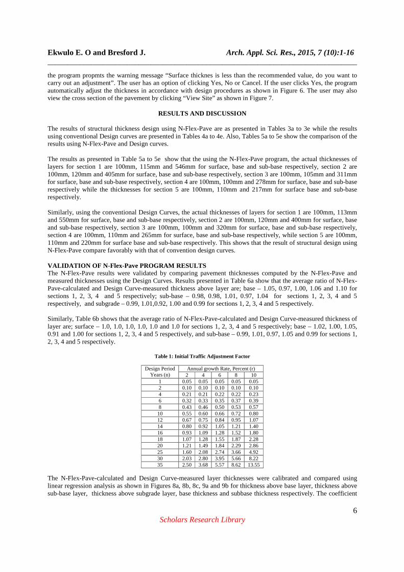
the program propmts the warning message “Surface thicknes is less than the recommended value, do you want to carry out an adjustment”. The user has an option of clicking Yes, No or Cancel. If the user clicks Yes, the program automatically adjust the thickness in accordance with design procedures as shown in Figure 6. The user may also view the cross section of the pavement by clicking “View Site” as shown in Figure 7.
RESULTS AND DISCUSSION
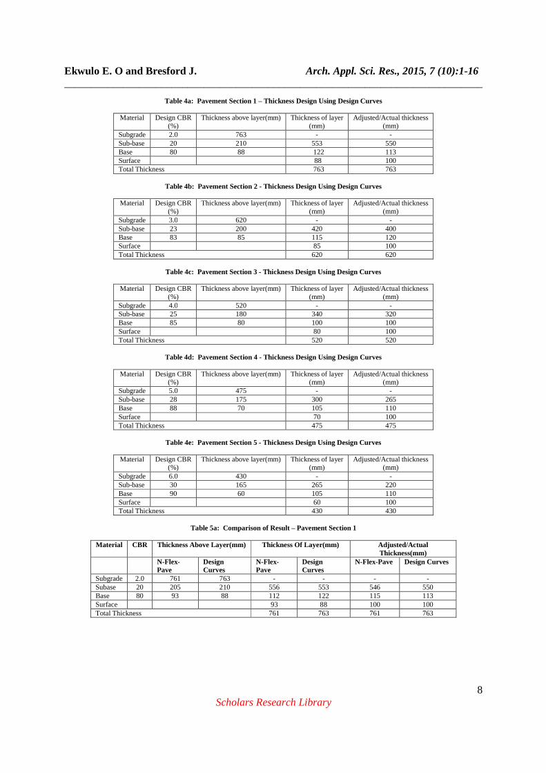
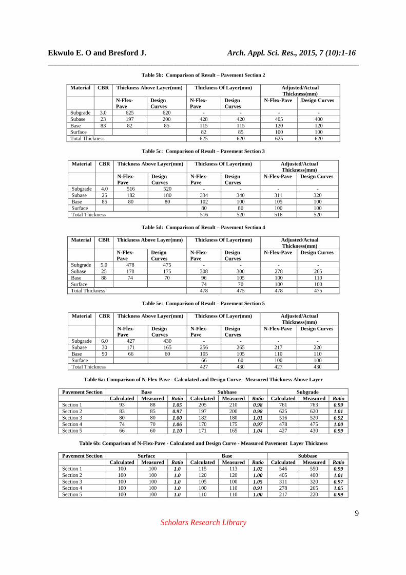
The results of structural thickness design using N-Flex-Pave are as presented in Tables 3a to 3e while the results using conventional Design curves are presented in Tables 4a to 4e. Also, Tables 5a to 5e show the comparison of the results using N-Flex-Pave and Design curves. The results as presented in Table 5a to 5e show that the using the N-Flex-Pave program, the actual thicknesses of layers for section 1 are 100mm, 115mm and 546mm for surface, base and sub-base respectively, section 2 are 100mm, 120mm and 405mm for surface, base and sub-base respectively, section 3 are 100mm, 105mm and 311mm for surface, base and sub-base respectively, section 4 are 100mm, 100mm and 278mm for surface, base and sub-base respectively while the thicknesses for section 5 are 100mm, 110mm and 217mm for surface base and sub-base respectively. Similarly, using the conventional Design Curves, the actual thicknesses of layers for section 1 are 100mm, 113mm and 550mm for surface, base and sub-base respectively, section 2 are 100mm, 120mm and 400mm for surface, base and sub-base respectively, section 3 are 100mm, 100mm and 320mm for surface, base and sub-base respectively, section 4 are 100mm, 110mm and 265mm for surface, base and sub-base respectively, while section 5 are 100mm, 110mm and 220mm for surface base and sub-base respectively. This shows that the result of structural design using N-Flex-Pave compare favorably with that of convention design curves. VALIDATION OF N-Flex-Pave PROGRAM RESULTS The N-Flex-Pave results were validated by comparing pavement thicknesses computed by the N-Flex-Pave and measured thicknesses using the Design Curves. Results presented in Table 6a show that the average ratio of N-Flex-Pave-calculated and Design Curve-measured thickness above layer are; base – 1.05, 0.97, 1.00, 1.06 and 1.10 for sections 1, 2, 3, 4 and 5 respectively; sub-base – 0.98, 0.98, 1.01, 0.97, 1.04 for sections 1, 2, 3, 4 and 5 respectively, and subgrade – 0.99, 1.01,0.92, 1.00 and 0.99 for sections 1, 2, 3, 4 and 5 respectively. Similarly, Table 6b shows that the average ratio of N-Flex-Pave-calculated and Design Curve-measured thickness of layer are; surface – 1.0, 1.0, 1.0, 1.0, 1.0 and 1.0 for sections 1, 2, 3, 4 and 5 respectively; base – 1.02, 1.00, 1.05, 0.91 and 1.00 for sections 1, 2, 3, 4 and 5 respectively, and sub-base – 0.99, 1.01, 0.97, 1.05 and 0.99 for sections 1, 2, 3, 4 and 5 respectively.
Table 1: Initial Traffic Adjustment Factor
Design Period Years (n)
Annual growth Rate, Percent (r) 2 4 6 8 10
1 0.05 0.05 0.05 0.05 0.05 2 0.10 0.10 0.10 0.10 0.10 4 0.21 0.21 0.22 0.22 0.23 6 0.32 0.33 0.35 0.37 0.39 8 0.43 0.46 0.50 0.53 0.57 10 0.55 0.60 0.66 0.72 0.80 12 0.67 0.75 0.84 0.95 1.07 14 0.80 0.92 1.05 1.21 1.40 16 0.93 1.09 1.28 1.52 1.80 18 1.07 1.28 1.55 1.87 2.28 20 1.21 1.49 1.84 2.29 2.86 25 1.60 2.08 2.74 3.66 4.92 30 2.03 2.80 3.95 5.66 8.22 35 2.50 3.68 5.57 8.62 13.55
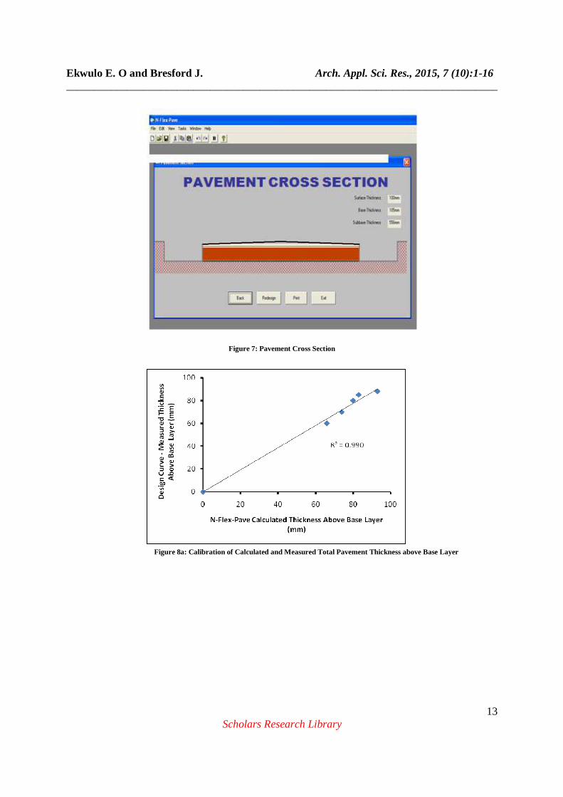
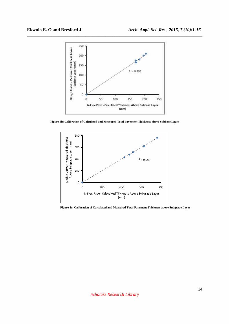
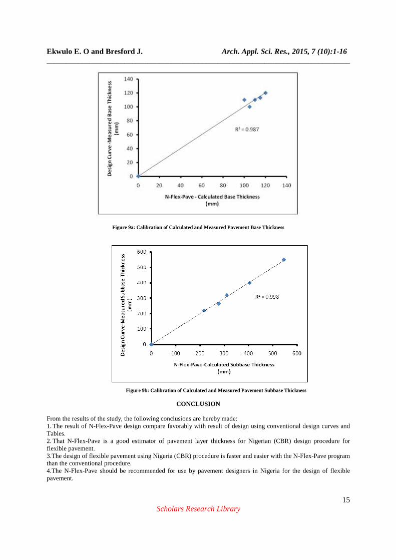
The N-Flex-Pave-calculated and Design Curve-measured layer thicknesses were calibrated and compared using linear regression analysis as shown in Figures 8a, 8b, 8c, 9a and 9b for thickness above base layer, thickness above sub-base layer, thickness above subgrade layer, base thickness and subbase thickness respectively. The coefficient
Ekwulo E. O and Bresford J. Arch. Appl. Sci. Res., 2015, 7 (10):1-16 ______________________________________________________________________________
7 Scholars Research Library
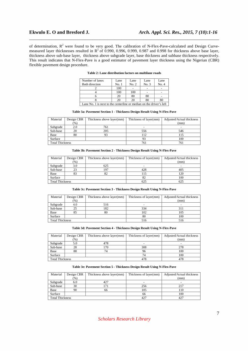
of determination, R2 were found to be very good. The calibration of N-Flex-Pave-calculated and Design Curve-measured layer thicknesses resulted in R2 of 0.990, 0.996, 0.999, 0.987 and 0.998 for thickness above base layer, thickness above sub-base layer, thickness above subgrade layer, base thickness and subbase thickness respectively. This result indicates that N-Flex-Pave is a good estimator of pavement layer thickness using the Nigerian (CBR) flexible pavement design procedure.
Table 2: Lane distribution factors on multilane roads
Number of lanes Both direction
Lane No. 1
Lane No. 2
Lane No. 3
Lane No. 4
2 100 - - - 4 100 100 - - 6 20 80 80 - 8 20 20 80 80
Lane No. 1 is next to the centerline or median on the driver’s left
Table 3a: Pavement Section 1 - Thickness Design Result Using N-Flex-Pave
Material Design CBR (%)
Thickness above layer(mm) Thickness of layer(mm) Adjusted/Actual thickness (mm)
Subgrade 2.0 761 - - Sub-base 20 205 556 546 Base 80 93 112 115 Surface 93 100 Total Thickness 761 761
Table 3b: Pavement Section 2 - Thickness Design Result Using N-Flex-Pave
Material Design CBR
(%) Thickness above layer(mm) Thickness of layer(mm) Adjusted/Actual thickness
(mm) Subgrade 3.0 625 - - Sub-base 23 197 428 405 Base 83 82 115 120 Surface 82 100 Total Thickness 625 625
Table 3c: Pavement Section 3 - Thickness Design Result Using N-Flex-Pave
Material Design CBR
(%) Thickness above layer(mm) Thickness of layer(mm) Adjusted/Actual thickness
(mm) Subgrade 4.0 516 - - Sub-base 25 182 334 311 Base 85 80 102 105 Surface 80 100 Total Thickness 516 516
Table 3d: Pavement Section 4 - Thickness Design Result Using N-Flex-Pave
Material Design CBR
(%) Thickness above layer(mm) Thickness of layer(mm) Adjusted/Actual thickness
(mm) Subgrade 5.0 478 - - Sub-base 28 170 308 278 Base 88 74 96 100 Surface 74 100 Total Thickness 478 478
Table 3e: Pavement Section 5 - Thickness Design Result Using N-Flex-Pave
Material Design CBR
(%) Thickness above layer(mm) Thickness of layer(mm) Adjusted/Actual thickness
(mm) Subgrade 6.0 427 - - Sub-base 30 171 256 217 Base 90 66 105 110 Surface 66 100 Total Thickness 427 427
Ekwulo E. O and Bresford J. Arch. Appl. Sci. Res., 2015, 7 (10):1-16 ______________________________________________________________________________
8 Scholars Research Library
Table 4a: Pavement Section 1 – Thickness Design Using Design Curves
Material Design CBR (%)
Thickness above layer(mm) Thickness of layer (mm)
Adjusted/Actual thickness (mm)
Subgrade 2.0 763 - - Sub-base 20 210 553 550 Base 80 88 122 113 Surface 88 100 Total Thickness 763 763
Table 4b: Pavement Section 2 - Thickness Design Using Design Curves
Material Design CBR
(%) Thickness above layer(mm) Thickness of layer
(mm) Adjusted/Actual thickness
(mm) Subgrade 3.0 620 - - Sub-base 23 200 420 400 Base 83 85 115 120 Surface 85 100 Total Thickness 620 620
Table 4c: Pavement Section 3 - Thickness Design Using Design Curves
Material Design CBR
(%) Thickness above layer(mm) Thickness of layer
(mm) Adjusted/Actual thickness
(mm) Subgrade 4.0 520 - - Sub-base 25 180 340 320 Base 85 80 100 100 Surface 80 100 Total Thickness 520 520
Table 4d: Pavement Section 4 - Thickness Design Using Design Curves
Material Design CBR
(%) Thickness above layer(mm) Thickness of layer
(mm) Adjusted/Actual thickness
(mm) Subgrade 5.0 475 - - Sub-base 28 175 300 265 Base 88 70 105 110 Surface 70 100 Total Thickness 475 475
Table 4e: Pavement Section 5 - Thickness Design Using Design Curves
Material Design CBR
(%) Thickness above layer(mm) Thickness of layer
(mm) Adjusted/Actual thickness
(mm) Subgrade 6.0 430 - - Sub-base 30 165 265 220 Base 90 60 105 110 Surface 60 100 Total Thickness 430 430
Table 5a: Comparison of Result – Pavement Section 1
Material CBR Thickness Above Layer(mm) Thickness Of Layer(mm) Adjusted/Actual
Thickness(mm) N-Flex-
Pave Design Curves
N-Flex-Pave
Design Curves
N-Flex-Pave Design Curves
Subgrade 2.0 761 763 - - - - Subase 20 205 210 556 553 546 550 Base 80 93 88 112 122 115 113 Surface 93 88 100 100 Total Thickness 761 763 761 763
Ekwulo E. O and Bresford J. Arch. Appl. Sci. Res., 2015, 7 (10):1-16 ______________________________________________________________________________
9 Scholars Research Library
Table 5b: Comparison of Result – Pavement Section 2
Material CBR Thickness Above Layer(mm) Thickness Of Layer(mm) Adjusted/Actual Thickness(mm)
N-Flex-Pave
Design Curves
N-Flex-Pave
Design Curves
N-Flex-Pave Design Curves
Subgrade 3.0 625 620 - - - - Subase 23 197 200 428 420 405 400 Base 83 82 85 115 115 120 120 Surface 82 85 100 100 Total Thickness 625 620 625 620
Table 5c: Comparison of Result – Pavement Section 3
Material CBR Thickness Above Layer(mm) Thickness Of Layer(mm) Adjusted/Actual
Thickness(mm) N-Flex-
Pave Design Curves
N-Flex-Pave
Design Curves
N-Flex-Pave Design Curves
Subgrade 4.0 516 520 - - - - Subase 25 182 180 334 340 311 320 Base 85 80 80 102 100 105 100 Surface 80 80 100 100 Total Thickness 516 520 516 520
Table 5d: Comparison of Result – Pavement Section 4
Material CBR Thickness Above Layer(mm) Thickness Of Layer(mm) Adjusted/Actual
Thickness(mm) N-Flex-
Pave Design Curves
N-Flex-Pave
Design Curves
N-Flex-Pave Design Curves
Subgrade 5.0 478 475 - - - - Subase 25 170 175 308 300 278 265 Base 88 74 70 96 105 100 110 Surface 74 70 100 100 Total Thickness 478 475 478 475
Table 5e: Comparison of Result – Pavement Section 5
Material CBR Thickness Above Layer(mm) Thickness Of Layer(mm) Adjusted/Actual
Thickness(mm) N-Flex-
Pave Design Curves
N-Flex-Pave
Design Curves
N-Flex-Pave Design Curves
Subgrade 6.0 427 430 - - - - Subase 30 171 165 256 265 217 220 Base 90 66 60 105 105 110 110 Surface 66 60 100 100 Total Thickness 427 430 427 430
Table 6a: Comparison of N-Flex-Pave - Calculated and Design Curve - Measured Thickness Above Layer
Pavement Section Base Subbase Subgrade Calculated Measured Ratio Calculated Measured Ratio Calculated Measured Ratio Section 1 93 88 1.05 205 210 0.98 761 763 0.99 Section 2 83 85 0.97 197 200 0.98 625 620 1.01 Section 3 80 80 1.00 182 180 1.01 516 520 0.92 Section 4 74 70 1.06 170 175 0.97 478 475 1.00 Section 5 66 60 1.10 171 165 1.04 427 430 0.99
Table 6b: Comparison of N-Flex-Pave - Calculated and Design Curve - Measured Pavement Layer Thickness
Pavement Section Surface Base Subbase Calculated Measured Ratio Calculated Measured Ratio Calculated Measured Ratio Section 1 100 100 1.0 115 113 1.02 546 550 0.99 Section 2 100 100 1.0 120 120 1.00 405 400 1.01 Section 3 100 100 1.0 105 100 1.05 311 320 0.97 Section 4 100 100 1.0 100 110 0.91 278 265 1.05 Section 5 100 100 1.0 110 110 1.00 217 220 0.99
Ekwulo E. O and Bresford J. Arch. Appl. Sci. Res., 2015, 7 (10):1-16 ______________________________________________________________________________
10 Scholars Research Library
Figure 2: Traffic Data Window– Step 1 of 4
Figure 1: The Nigerian (CBR) Flexible Pavement Design Chart
Ekwulo E. O and Bresford J. Arch. Appl. Sci. Res., 2015, 7 (10):1-16 ______________________________________________________________________________
11 Scholars Research Library
Figure 3: Material Parameter Window – Step 2 of 4
Figure 4: Thickness Above Layer Window
Ekwulo E. O and Bresford J. Arch. Appl. Sci. Res., 2015, 7 (10):1-16 ______________________________________________________________________________
12 Scholars Research Library
Figure 5: Thickness of Layer Window
Figure 6: Thickness Adjustment Window
Ekwulo E. O and Bresford J. Arch. Appl. Sci. Res., 2015, 7 (10):1-16 ______________________________________________________________________________
13 Scholars Research Library
Figure 7: Pavement Cross Section
Figure 8a: Calibration of Calculated and Measured Total Pavement Thickness above Base Layer
Ekwulo E. O and Bresford J. Arch. Appl. Sci. Res., 2015, 7 (10):1-16 ______________________________________________________________________________
14 Scholars Research Library
Figure 8b: Calibration of Calculated and Measured Total Pavement Thickness above Subbase Layer
Figure 8c: Calibration of Calculated and Measured Total Pavement Thickness above Subgrade Layer
Ekwulo E. O and Bresford J. Arch. Appl. Sci. Res., 2015, 7 (10):1-16 ______________________________________________________________________________
15 Scholars Research Library
Figure 9a: Calibration of Calculated and Measured Pavement Base Thickness
CONCLUSION
From the results of the study, the following conclusions are hereby made: 1. The result of N-Flex-Pave design compare favorably with result of design using conventional design curves and Tables. 2. That N-Flex-Pave is a good estimator of pavement layer thickness for Nigerian (CBR) design procedure for flexible pavement. 3.The design of flexible pavement using Nigeria (CBR) procedure is faster and easier with the N-Flex-Pave program than the conventional procedure. 4.The N-Flex-Pave should be recommended for use by pavement designers in Nigeria for the design of flexible pavement.
Figure 9b: Calibration of Calculated and Measured Pavement Subbase Thickness
Ekwulo E. O and Bresford J. Arch. Appl. Sci. Res., 2015, 7 (10):1-16 ______________________________________________________________________________
16 Scholars Research Library
REFERENCES [1] Road Research Laboratory, , “A Guide to the Structural Design of Pavement for New Roads –Road Note 29” 3rd Edition, Department of Environment, HMSO, London, (1970). [2] Highway Manuel –Part 1 Design, Federal Ministry of Works, Lagos (1973). [3] American Association of State Highway and Transportation Officials AASHTO, AASHTO Guide for Design of Pavement structures, Washington, D.C (1993). [4] D.M. Burmister. Journal of Applied Physics, 1945. [5] H. Warren, W. L. Dieckman. Numerical Computational Stresses and Strains in Multi-Layer Asphalt Pavement System, Internal Report, Cheron Research Corporation, Richmond, CA. 1963. [6] D. Huang, M. W. Witczack, Program DAMA (Chevron), User’s Manual, Department of Civil Engineering, University of Maryland, (1983). [7] G. Ahlborn. ELSYM5 [Computer Program for Determining Stresses and Strains in Five Layer System]. University of California, Berkeley (1972). [8] S. Kopperman, G. Tiller, M. Tseng. ELSYM5, Interactive Microcomputer Version, User’s Manual, Report No. FHWA-TA-87-206, Federal Highway Administration (1986). [9] N. Sivaneswaran, L. M. Piecce, J. S. Ulmeyer. Everstress (Version 5.0) [Layered Elastic Analysis Program] Washington State Department of Transportation (2001) [10] L. Raad, J. L. Figueroa. Transportation Engineering Journal, ASCE , 1980, Vol. 106, No. TE1, pp. 111-128 [11] R. S. Harichandran, Y. Ming-Shah, Y. B. Gilbert. MICH_PAVE, A Nonlinear Finite Element Program for Analysis of Flexible Pavement, Transportation Research Records No. 1286 pp. 123-131 (1990) [12] Y. Cho, B. F. McCullough, J. Weissmann. Transportation Research Record, no.1322, pp.112-121 (1996) [13] H. Howard., Visual Basic 6.0, MSCD Training Guide, New Riders Publishers, USA (1999).