development of computerized electronic … /archive-2016/august-2016/96.pdf · boredom, boredom...
TRANSCRIPT
[Bustillo* et al., 5(8): August, 2016] ISSN: 2277-9655
IC™ Value: 3.00 Impact Factor: 4.116
http: // www.ijesrt.com © International Journal of Engineering Sciences & Research Technology
[833]
IJESRT INTERNATIONAL JOURNAL OF ENGINEERING SCIENCES & RESEARCH
TECHNOLOGY
DEVELOPMENT OF COMPUTERIZED ELECTRONIC COUNTER AND TIMER
USING LCD MONITOR IN NAVAL STATE UNIVERSITY Reynold Garcia Bustillo, Homer Ricacho Ampong
Naval State University, Naval, Biliran Province, Philippines
DOI: 10.5281/zenodo.60755
ABSTRACT The main objective of this study was to develop a computerized electronic counter and timer using LCD monitor to
be used in cashier’s office of Naval State University, Naval, Biliran, Philippines. This study used the application
rapid development as a tool in making the project. The Computerized Electronic Counter and Timer Using LCD
Monitor was designed to ease the effort and boredoms of the students falling in line waiting for their turn to be
entertain by the cashier in whatsoever purposes they have. It is a great help to the administrator in making the students
entertain while they are waiting for their turn. It may also be a venture for the administrator to post important
announcements to the students. Computerized Electronic Counter and Timer Using LCD Monitor was design taking
into account various industry needs and practices. The system is an ideal solution for one service environment such
as the cashier, thus optimizing the space and enhancing the office operational efficiency. Computerized Electronic
Counter and Timer Using LCD Monitor is a simple and user friendly system which has teller button service whereby
the teller/agent instantly calls the next customer in the queue. This system is also equipped with a ticketing dispenser,
and display units alerting the customer to proceed to the available counter, video player for the customer to be
entertain while waiting, and a moving text to post important announcements. Moreover, more than one single line
queue systems can also be integrated together allowing more teller’s/agents to serve increasing customers. This
system allows us to enhance the customer experience in any environment. There is a need of future study to enhance
the implementation of this system.
KEYWORDS: Computerized; Electronic Counter; LCD Monitor; Timer.
INTRODUCTIONIn the present generation where Information Technology becomes larger and more refined as it rapidly developing,
usage of electronic machines and gadgets even in the simplest way is very helpful. Development in Information
Technology indeed makes our daily life easier and effortless through modernization. It is really true that with the
advancement in the area of computation, the role of human had decreased drastically but not completely (Mohamad,
2007).
Standing in a long queue or waiting for your turn is not anyone’s favorite activity. It is the low quality of service which
results in long waits thus decreasing the efficiency of the organization. Many industries face enormous customer
footfall and companies have to serve more people than it can handle.
EQMS (2014) contended that consulting; customers always over estimate their wait time by 50%. Waiting is extremely
frustrating, distressful and time consuming. Failure in meeting the time service expectation of a customer leads to
boredom, boredom leads to frustration, and frustration leads to argument. It is obviously the problem seen by the
respondents in any transactions at the Naval State University especially at the cashier during enrolment and
examination period.
[Bustillo* et al., 5(8): August, 2016] ISSN: 2277-9655
IC™ Value: 3.00 Impact Factor: 4.116
http: // www.ijesrt.com © International Journal of Engineering Sciences & Research Technology
[834]
With this regard, the proponents present a prototype computerized electronic counter and timer using LCD monitor
which help the institution and their employees to manage, track and prioritize the service to ensure timely and efficient
delivery to every customer.
It is the system which has an exceptional customer experience through Single & Multiple line queue system. Moreover,
the system has the capability to inform and entertain the customers through a video presentation and moving text. This
might be the solutions in reducing wait time and arguments in any school transactions. It may also provide fair delivery
and in return eliminate stress among the customers. It is on this premised that the proponents motivated to conduct
this study to s good delivery of service. (Benjaafar, S., Gayon, J., and Tepe, S., 2010).
OBJECTIVES OF THE STUDY This study aimed to develop a Computerized Electronic Counter and Timer using LCD Monitor for the Cashier’s
Office of the Naval State University. Specifically, the study sought to attain the following objectives:
[1] Promote and maintain orderliness in queuing at the cashier’s office during payment period.
[2] Inform students with the latest news about the university through scrolling text
[3] Entertain the students while waiting for their transaction.
[4] Prevent insertion of those students who are not following the rules during payment period.
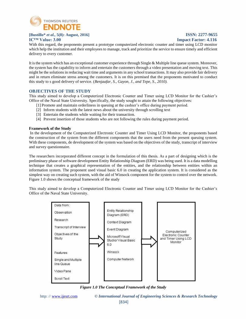
Framework of the Study
In the development of the Computerized Electronic Counter and Timer Using LCD Monitor, the proponents based
the construction of the system from the different components that the users need from the present queuing system.
With these components, de development of the system was based on the objectives of the study, transcript of interview
and survey questionnaire.
The researchers incorporated different concept in the formulation of this thesis. As a part of designing which is the
preliminary phase of software development Entity Relationship Diagram (ERD) was being used. It is a data modelling
technique that creates a graphical representation of the entities, and the relationship between entities within an
information system. The proponent used visual basic 6.0 in creating the application system. It is considered as the
simplest way on creating such system, with the aid of Winsock component for the system to control over the network.
Figure 1.0 shows the conceptual framework of the study
This study aimed to develop a Computerized Electronic Counter and Timer using LCD Monitor for the Cashier’s
Office of the Naval State University.
Figure 1.0 The Conceptual Framework of the Study
[Bustillo* et al., 5(8): August, 2016] ISSN: 2277-9655
IC™ Value: 3.00 Impact Factor: 4.116
http: // www.ijesrt.com © International Journal of Engineering Sciences & Research Technology
[835]
Scope and Delimitation of the Study This study only focuses on the development of computerized electronic counter and timer using LCD monitor at the
cashier’s office for this S.Y. 2014-2015.
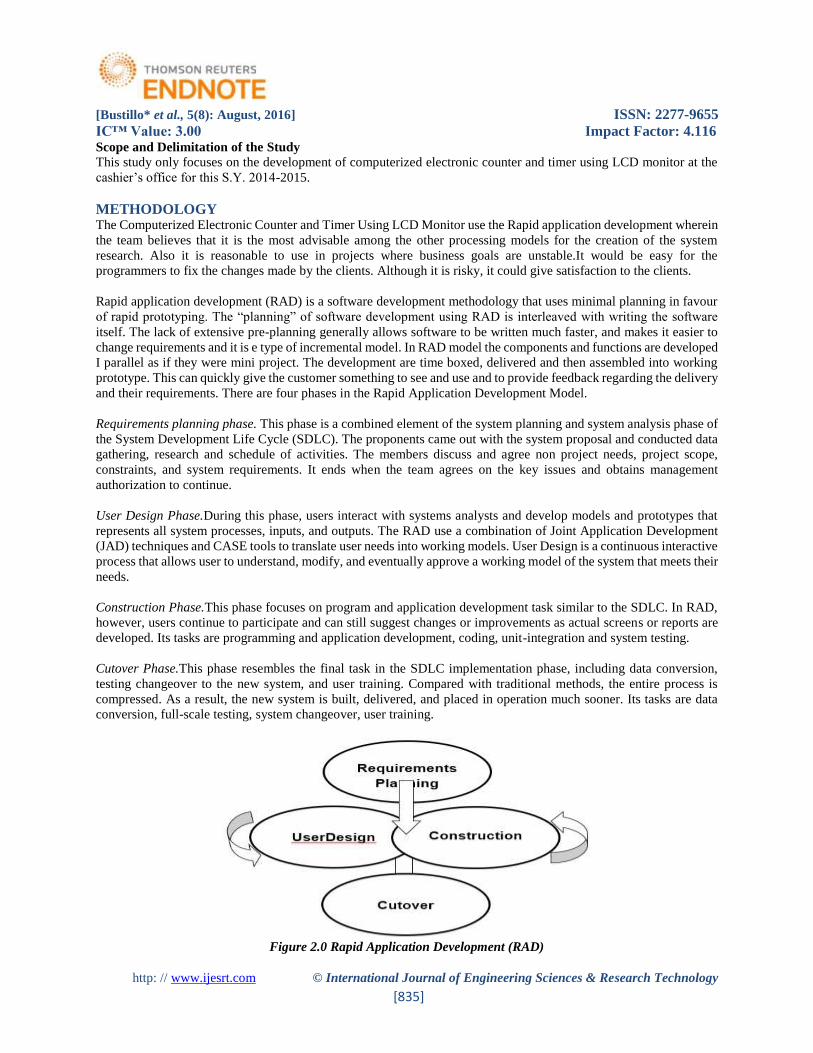
METHODOLOGY The Computerized Electronic Counter and Timer Using LCD Monitor use the Rapid application development wherein
the team believes that it is the most advisable among the other processing models for the creation of the system
research. Also it is reasonable to use in projects where business goals are unstable.It would be easy for the
programmers to fix the changes made by the clients. Although it is risky, it could give satisfaction to the clients.
Rapid application development (RAD) is a software development methodology that uses minimal planning in favour
of rapid prototyping. The “planning” of software development using RAD is interleaved with writing the software
itself. The lack of extensive pre-planning generally allows software to be written much faster, and makes it easier to
change requirements and it is e type of incremental model. In RAD model the components and functions are developed
I parallel as if they were mini project. The development are time boxed, delivered and then assembled into working
prototype. This can quickly give the customer something to see and use and to provide feedback regarding the delivery
and their requirements. There are four phases in the Rapid Application Development Model.
Requirements planning phase. This phase is a combined element of the system planning and system analysis phase of
the System Development Life Cycle (SDLC). The proponents came out with the system proposal and conducted data
gathering, research and schedule of activities. The members discuss and agree non project needs, project scope,
constraints, and system requirements. It ends when the team agrees on the key issues and obtains management
authorization to continue.
User Design Phase.During this phase, users interact with systems analysts and develop models and prototypes that
represents all system processes, inputs, and outputs. The RAD use a combination of Joint Application Development
(JAD) techniques and CASE tools to translate user needs into working models. User Design is a continuous interactive
process that allows user to understand, modify, and eventually approve a working model of the system that meets their
needs.
Construction Phase.This phase focuses on program and application development task similar to the SDLC. In RAD,
however, users continue to participate and can still suggest changes or improvements as actual screens or reports are
developed. Its tasks are programming and application development, coding, unit-integration and system testing.
Cutover Phase.This phase resembles the final task in the SDLC implementation phase, including data conversion,
testing changeover to the new system, and user training. Compared with traditional methods, the entire process is
compressed. As a result, the new system is built, delivered, and placed in operation much sooner. Its tasks are data
conversion, full-scale testing, system changeover, user training.
Figure 2.0 Rapid Application Development (RAD)
[Bustillo* et al., 5(8): August, 2016] ISSN: 2277-9655
IC™ Value: 3.00 Impact Factor: 4.116
http: // www.ijesrt.com © International Journal of Engineering Sciences & Research Technology
[836]
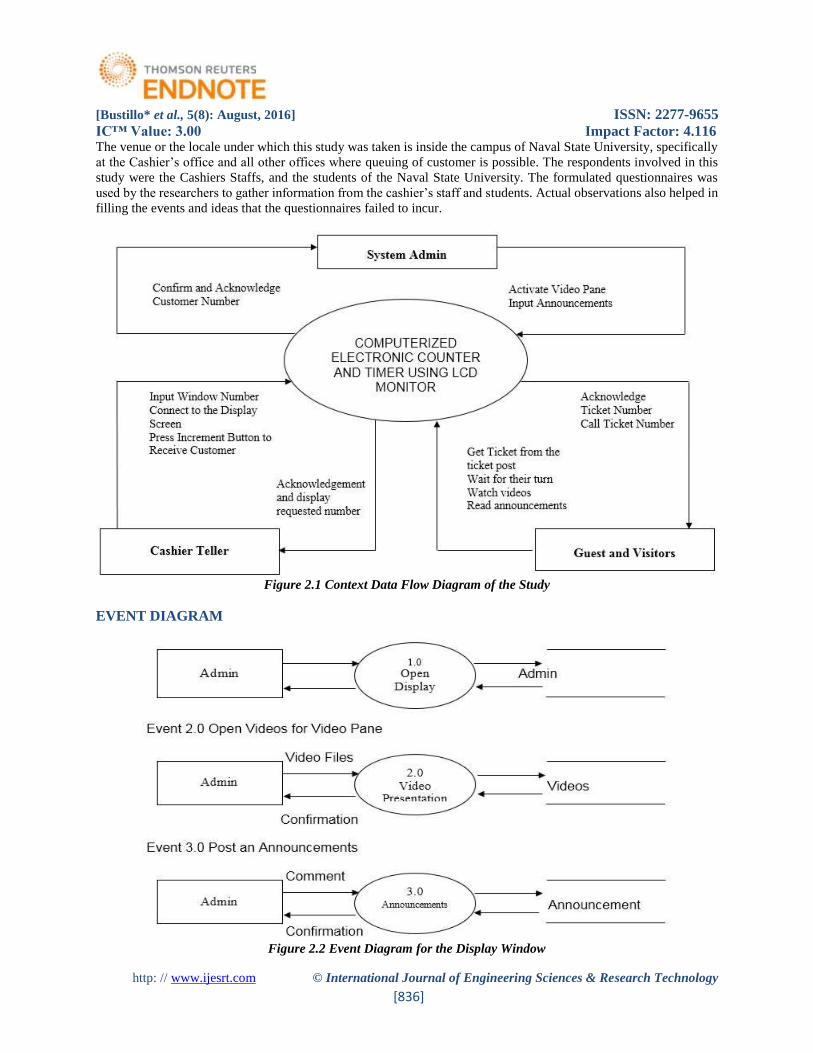
The venue or the locale under which this study was taken is inside the campus of Naval State University, specifically
at the Cashier’s office and all other offices where queuing of customer is possible. The respondents involved in this
study were the Cashiers Staffs, and the students of the Naval State University. The formulated questionnaires was
used by the researchers to gather information from the cashier’s staff and students. Actual observations also helped in
filling the events and ideas that the questionnaires failed to incur.
Figure 2.1 Context Data Flow Diagram of the Study
EVENT DIAGRAM
Figure 2.2 Event Diagram for the Display Window
[Bustillo* et al., 5(8): August, 2016] ISSN: 2277-9655
IC™ Value: 3.00 Impact Factor: 4.116
http: // www.ijesrt.com © International Journal of Engineering Sciences & Research Technology
[837]
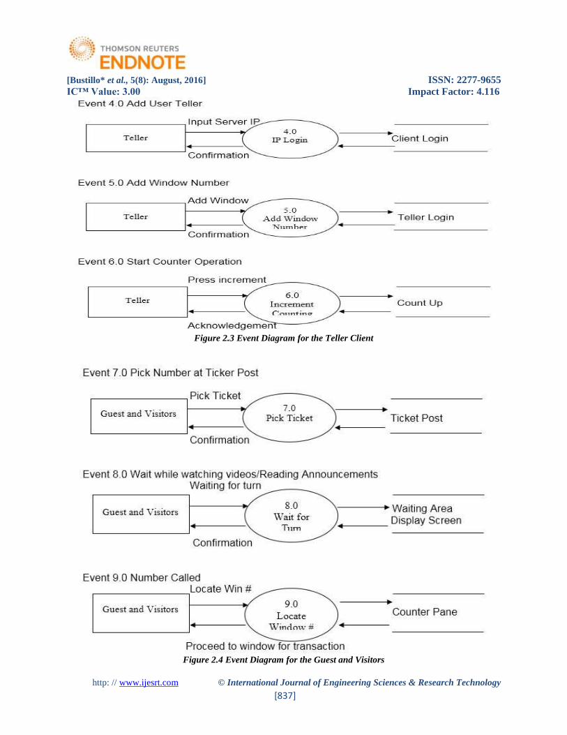
Figure 2.3 Event Diagram for the Teller Client
Figure 2.4 Event Diagram for the Guest and Visitors
[Bustillo* et al., 5(8): August, 2016] ISSN: 2277-9655
IC™ Value: 3.00 Impact Factor: 4.116
http: // www.ijesrt.com © International Journal of Engineering Sciences & Research Technology
[838]
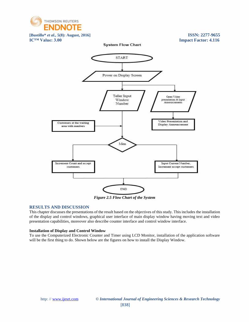
Figure 2.5 Flow Chart of the System
RESULTS AND DISCUSSION This chapter discusses the presentations of the result based on the objectives of this study. This includes the installation
of the display and control windows, graphical user interface of main display window having moving text and video
presentation capabilities, moreover also describe counter interface and control window interface.
Installation of Display and Control Window
To use the Computerized Electronic Counter and Timer using LCD Monitor, installation of the application software
will be the first thing to do. Shown below are the figures on how to install the Display Window.
[Bustillo* et al., 5(8): August, 2016] ISSN: 2277-9655
IC™ Value: 3.00 Impact Factor: 4.116
http: // www.ijesrt.com © International Journal of Engineering Sciences & Research Technology
[839]
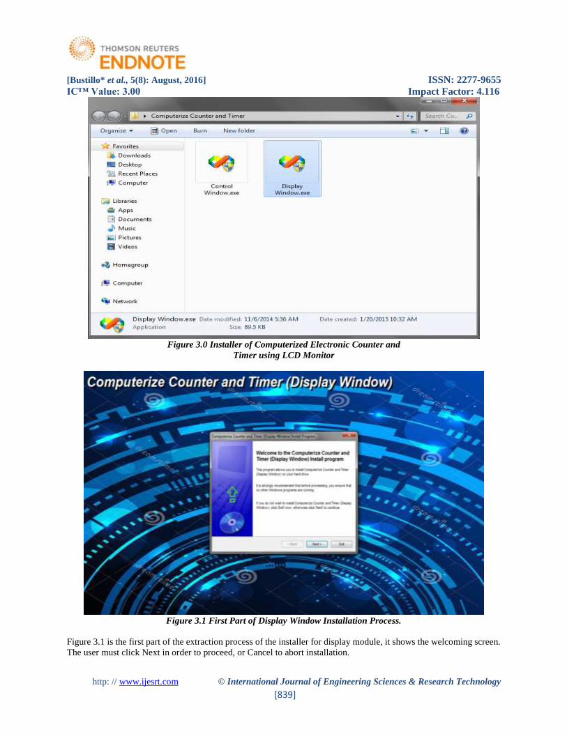
Figure 3.0 Installer of Computerized Electronic Counter and
Timer using LCD Monitor
Figure 3.1 First Part of Display Window Installation Process.
Figure 3.1 is the first part of the extraction process of the installer for display module, it shows the welcoming screen.
The user must click Next in order to proceed, or Cancel to abort installation.
[Bustillo* et al., 5(8): August, 2016] ISSN: 2277-9655
IC™ Value: 3.00 Impact Factor: 4.116
http: // www.ijesrt.com © International Journal of Engineering Sciences & Research Technology
[840]
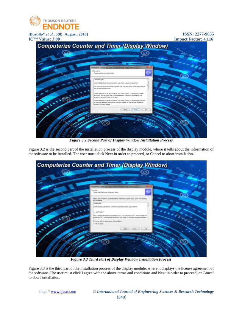
Figure 3.2 Second Part of Display Window Installation Process
Figure 3.2 is the second part of the installation process of the display module, where it tells about the information of
the software to be installed. The user must click Next in order to proceed, or Cancel to abort installation.
Figure 3.3 Third Part of Display Window Installation Process
Figure 3.3 is the third part of the installation process of the display module, where it displays the license agreement of
the software. The user must click I agree with the above terms and conditions and Next in order to proceed, or Cancel
to abort installation.
[Bustillo* et al., 5(8): August, 2016] ISSN: 2277-9655
IC™ Value: 3.00 Impact Factor: 4.116
http: // www.ijesrt.com © International Journal of Engineering Sciences & Research Technology
[841]
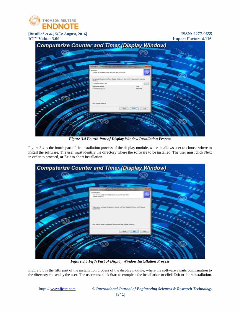
Figure 3.4 Fourth Part of Display Window Installation Process
Figure 3.4 is the fourth part of the installation process of the display module, where it allows user to choose where to
install the software. The user must identify the directory where the software to be installed. The user must click Next
in order to proceed, or Exit to abort installation.
Figure 3.5 Fifth Part of Display Window Installation Process
Figure 3.5 is the fifth part of the installation process of the display module, where the software awaits confirmation to
the directory chosen by the user. The user must click Start to complete the installation or click Exit to abort installation.
[Bustillo* et al., 5(8): August, 2016] ISSN: 2277-9655
IC™ Value: 3.00 Impact Factor: 4.116
http: // www.ijesrt.com © International Journal of Engineering Sciences & Research Technology
[842]
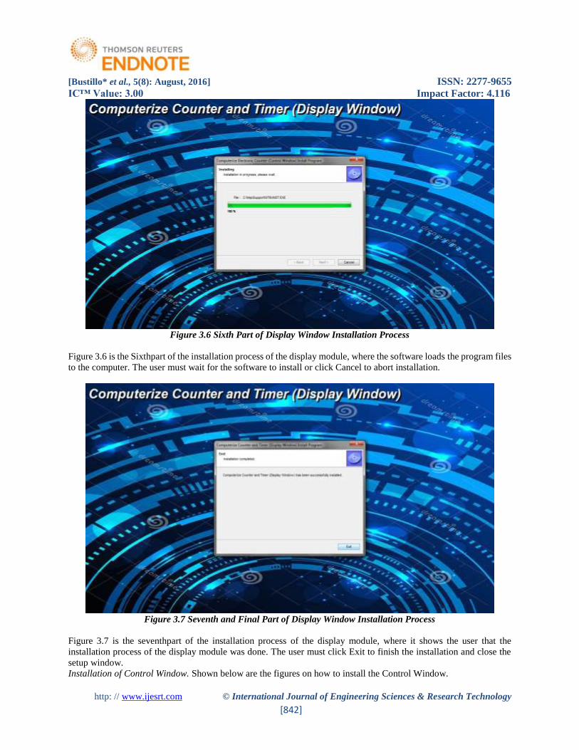
Figure 3.6 Sixth Part of Display Window Installation Process
Figure 3.6 is the Sixthpart of the installation process of the display module, where the software loads the program files
to the computer. The user must wait for the software to install or click Cancel to abort installation.
Figure 3.7 Seventh and Final Part of Display Window Installation Process
Figure 3.7 is the seventhpart of the installation process of the display module, where it shows the user that the
installation process of the display module was done. The user must click Exit to finish the installation and close the
setup window.
Installation of Control Window. Shown below are the figures on how to install the Control Window.
[Bustillo* et al., 5(8): August, 2016] ISSN: 2277-9655
IC™ Value: 3.00 Impact Factor: 4.116
http: // www.ijesrt.com © International Journal of Engineering Sciences & Research Technology
[843]
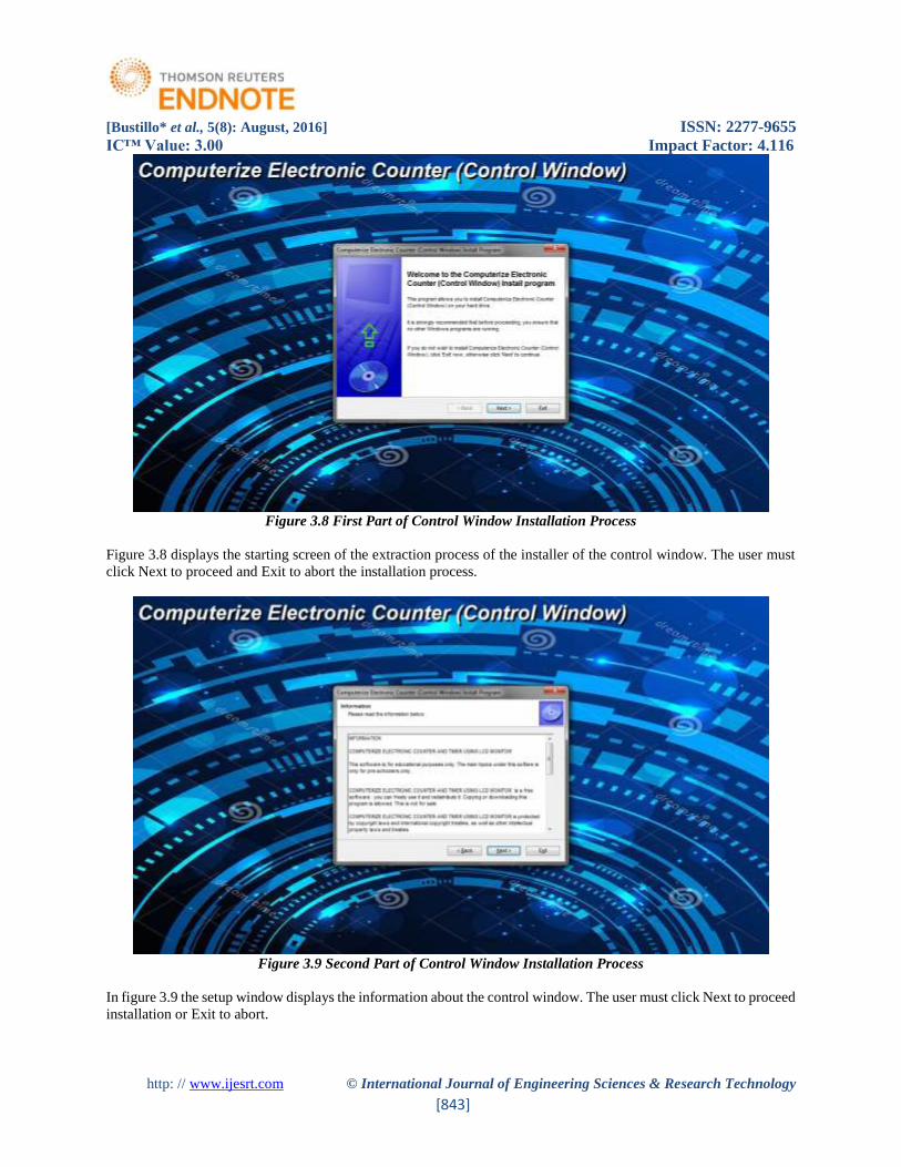
Figure 3.8 First Part of Control Window Installation Process
Figure 3.8 displays the starting screen of the extraction process of the installer of the control window. The user must
click Next to proceed and Exit to abort the installation process.
Figure 3.9 Second Part of Control Window Installation Process
In figure 3.9 the setup window displays the information about the control window. The user must click Next to proceed
installation or Exit to abort.
[Bustillo* et al., 5(8): August, 2016] ISSN: 2277-9655
IC™ Value: 3.00 Impact Factor: 4.116
http: // www.ijesrt.com © International Journal of Engineering Sciences & Research Technology
[844]
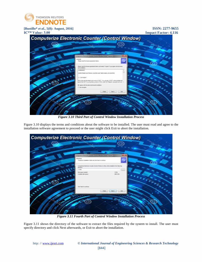
Figure 3.10 Third Part of Control Window Installation Process
Figure 3.10 displays the terms and conditions about the software to be installed. The user must read and agree to the
installation software agreement to proceed or the user might click Exit to abort the installation.
Figure 3.11 Fourth Part of Control Window Installation Process
Figure 3.11 shows the directory of the software to extract the files required by the system to install. The user must
specify directory and click Next afterwards, or Exit to abort the installation.
[Bustillo* et al., 5(8): August, 2016] ISSN: 2277-9655
IC™ Value: 3.00 Impact Factor: 4.116
http: // www.ijesrt.com © International Journal of Engineering Sciences & Research Technology
[845]
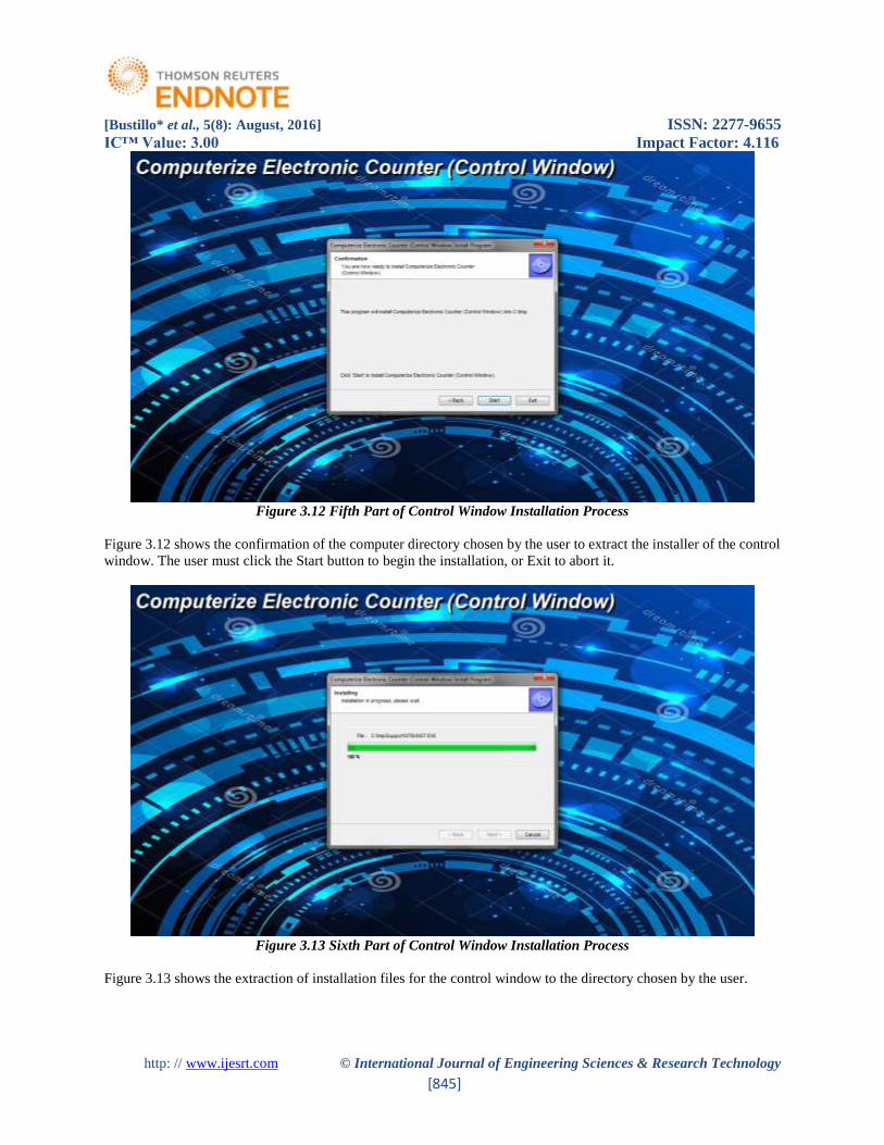
Figure 3.12 Fifth Part of Control Window Installation Process
Figure 3.12 shows the confirmation of the computer directory chosen by the user to extract the installer of the control
window. The user must click the Start button to begin the installation, or Exit to abort it.
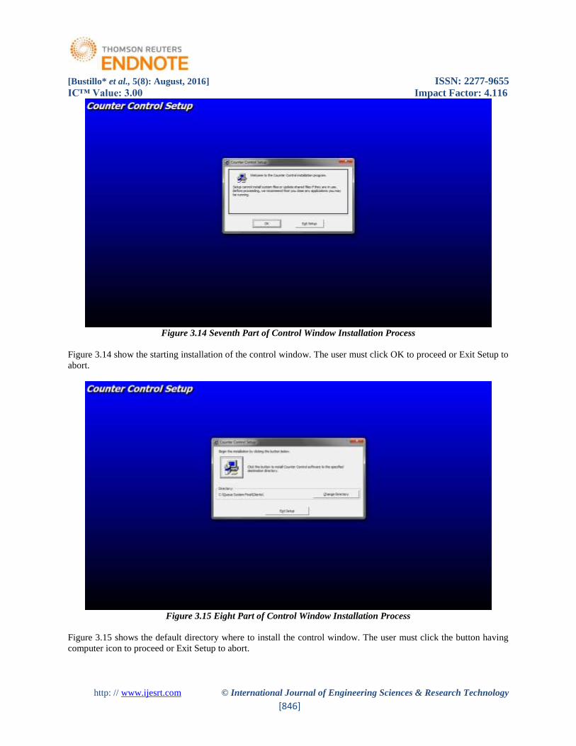
Figure 3.13 Sixth Part of Control Window Installation Process
Figure 3.13 shows the extraction of installation files for the control window to the directory chosen by the user.
[Bustillo* et al., 5(8): August, 2016] ISSN: 2277-9655
IC™ Value: 3.00 Impact Factor: 4.116
http: // www.ijesrt.com © International Journal of Engineering Sciences & Research Technology
[846]
Figure 3.14 Seventh Part of Control Window Installation Process
Figure 3.14 show the starting installation of the control window. The user must click OK to proceed or Exit Setup to
abort.
Figure 3.15 Eight Part of Control Window Installation Process
Figure 3.15 shows the default directory where to install the control window. The user must click the button having
computer icon to proceed or Exit Setup to abort.
[Bustillo* et al., 5(8): August, 2016] ISSN: 2277-9655
IC™ Value: 3.00 Impact Factor: 4.116
http: // www.ijesrt.com © International Journal of Engineering Sciences & Research Technology
[847]
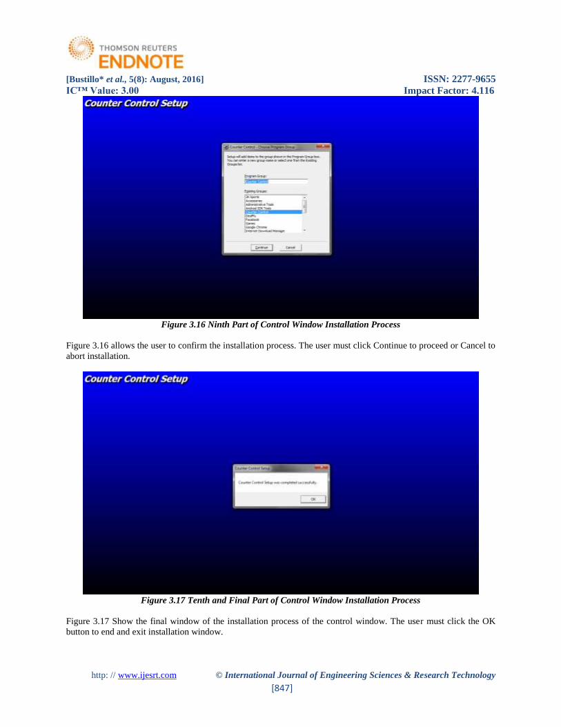
Figure 3.16 Ninth Part of Control Window Installation Process
Figure 3.16 allows the user to confirm the installation process. The user must click Continue to proceed or Cancel to
abort installation.
Figure 3.17 Tenth and Final Part of Control Window Installation Process
Figure 3.17 Show the final window of the installation process of the control window. The user must click the OK
button to end and exit installation window.
[Bustillo* et al., 5(8): August, 2016] ISSN: 2277-9655
IC™ Value: 3.00 Impact Factor: 4.116
http: // www.ijesrt.com © International Journal of Engineering Sciences & Research Technology
[848]
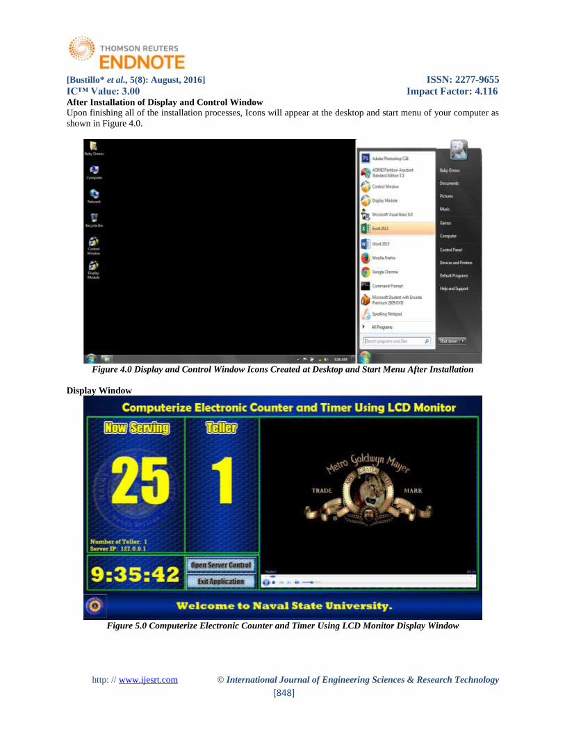
After Installation of Display and Control Window
Upon finishing all of the installation processes, Icons will appear at the desktop and start menu of your computer as
shown in Figure 4.0.
Figure 4.0 Display and Control Window Icons Created at Desktop and Start Menu After Installation
Display Window
Figure 5.0 Computerize Electronic Counter and Timer Using LCD Monitor Display Window
[Bustillo* et al., 5(8): August, 2016] ISSN: 2277-9655
IC™ Value: 3.00 Impact Factor: 4.116
http: // www.ijesrt.com © International Journal of Engineering Sciences & Research Technology
[849]
Figure 5.0 shows snapshot of the working display window of the system. It illustrates the service it can render in real
working condition especially in the queuing at the cashier’s office of the Naval State University. The display window
has ten features;
Counter.Serves as the queuing sequence of the customers having ticket;
Teller Number.Represents the window number at the cashier’s office;
Number of Teller Available.Shows how many available tellers for Service;
Digital Time Clock.Allows customers be oriented on what time it is;
Video Player.Entertains customers through video or movie showing while waiting;
Scrolling Text.Scrolling text can be useful for the administration to post News and Announcements for the
customers to the students, faculty and staff;
Playlist. The system has an ability to store video, movies and music in a playlist;
Network Controlled.The counter of the display window is controlled by a control window which is installed
on a computer connected through network;
User Friendly.All of the operations of this system is based on a windows application to secure a user friendly
interface that can be usedby an average computer user;
Supports Full Screen Resolution. The display window is a full screen resolution having a minimum of 1366
x 768. Thus, the system can also run using LED monitors capable of higher resolutions.
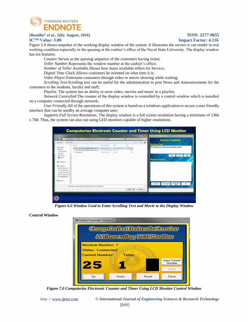
Figure 6.0 Window Used to Enter Scrolling Text and Movie to the Display Window
Control Window
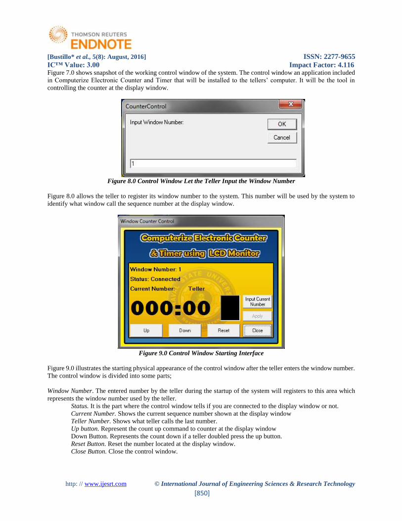
Figure 7.0 Computerize Electronic Counter and Timer Using LCD Monitor Control Window
[Bustillo* et al., 5(8): August, 2016] ISSN: 2277-9655
IC™ Value: 3.00 Impact Factor: 4.116
http: // www.ijesrt.com © International Journal of Engineering Sciences & Research Technology
[850]
Figure 7.0 shows snapshot of the working control window of the system. The control window an application included
in Computerize Electronic Counter and Timer that will be installed to the tellers’ computer. It will be the tool in
controlling the counter at the display window.
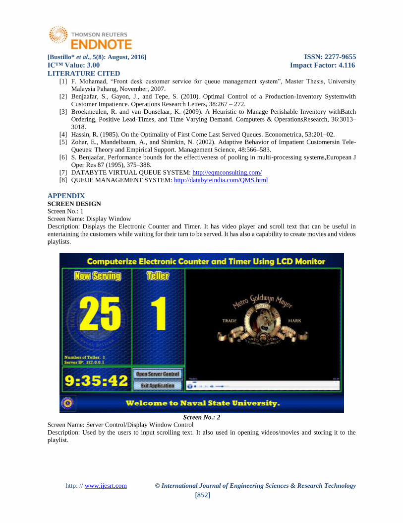
Figure 8.0 Control Window Let the Teller Input the Window Number
Figure 8.0 allows the teller to register its window number to the system. This number will be used by the system to
identify what window call the sequence number at the display window.
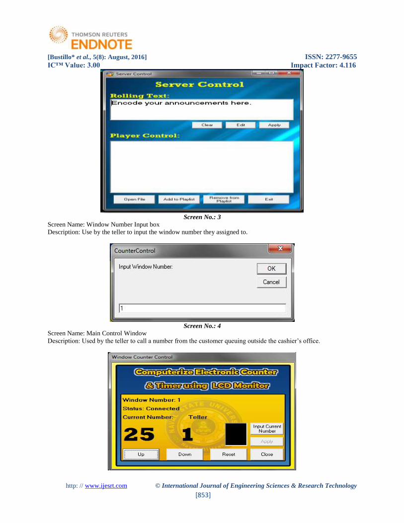
Figure 9.0 Control Window Starting Interface
Figure 9.0 illustrates the starting physical appearance of the control window after the teller enters the window number.
The control window is divided into some parts;
Window Number. The entered number by the teller during the startup of the system will registers to this area which
represents the window number used by the teller.
Status. It is the part where the control window tells if you are connected to the display window or not.
Current Number. Shows the current sequence number shown at the display window
Teller Number. Shows what teller calls the last number.
Up button. Represent the count up command to counter at the display window
Down Button. Represents the count down if a teller doubled press the up button.
Reset Button. Reset the number located at the display window.
Close Button. Close the control window.

[Bustillo* et al., 5(8): August, 2016] ISSN: 2277-9655
IC™ Value: 3.00 Impact Factor: 4.116
http: // www.ijesrt.com © International Journal of Engineering Sciences & Research Technology
[851]
Input Current Number Button. Serves asan emergency purpose button in terms of brownouts. The teller can enter the
current available number at the queue outside before brownout for it to display at the counter display window, then
they can proceed with the count up process.
Requirements Analysis and Specification Hardware Requirements. The proposed system run in network environment, it needs a client-server computer.Its
minimum system requires a Pentium 4 or higher computer specification, at least 1 GB memory, and 100 MB Hard
Drive space.
Software Requirements. The system can run perfectly with Windows XP Service Pack II (SP2) or higher windows
operating system.
Software and Application Being Used
The software application being used to develop the system is Microsoft Visual Basic 6.0. It was chosen by the
proponents for it is the simplest and most suitable application builder software that can cater full functionality of the
system.
Personnel
Personnel involve in using this system is the tellers and staff of the cashier’s office. They have all the authority to use
the system, for this system is intended for them to improve more their tasks.
Testing Strategies
Functionality Testing. Computerize Electronic Counter and Timer using LCD Monitor should undergo testing to
eliminate errors that usually occur from constant running of the program. Various testing activities were conducted
during the defense to check the systems performance and back end of this project.
System Testing. Users should evaluate the system accurately. Series of test should be conducted to ensure the flow of
the system in able to detect and debug immediately the error that may occur.
Installation and Maintenance Process
With the hardware and software requirements will be set up correctly, it till be followed by the installation of the
Computerize Electronic Counter and Timer using LCD Monitor. Instructions and User’s Manual should be properly
observed.
CONCLUSIONS Based on the findings of this research, the following conclusion are drawn Computerized Electronic Counter and
Timer using LCD Monitor for cashier’s Office. Computerized Electronic Counter and Timer using LCD Monitor
promotes and maintain orderliness in queuing at the cashier’s office during payment period. It Inform students with
the latest news about the university through scrolling text. It also entertains the students while waiting for their
transaction. Moreover, it prevents insertion of those students who are not following the rules during payment period.
Thus, Computerized Electronic Counter and Timer using LCD Monitor is relevant to the NSU cashier’s office and
students because the system will make their transaction fairly, easier, faster, most of all it is entertaining and less
stressful.
RECOMMENDATIONS In the light of the findings the following conclusions are forwarded: Replacement of system with the latest
Computerized Electronic Counter and Timer Using LCD Monitor comes with the sense of urgency. For the realization
and implementation of the Computerize Electronic Counter and Timer using LCD Monitor, both hardware and
software requirements should be followed. The administration should put up the number ticketing post near the
cashier’s office where the numbers are available. Further research should be conducted in region wide for the future
researchers with the same interest on Computerize Electronic Counter and Timer using LCD Monitor to optimize the
result of the present study.
[Bustillo* et al., 5(8): August, 2016] ISSN: 2277-9655
IC™ Value: 3.00 Impact Factor: 4.116
http: // www.ijesrt.com © International Journal of Engineering Sciences & Research Technology
[852]
LITERATURE CITED [1] F. Mohamad, “Front desk customer service for queue management system”, Master Thesis, University
Malaysia Pahang, November, 2007.
[2] Benjaafar, S., Gayon, J., and Tepe, S. (2010). Optimal Control of a Production-Inventory Systemwith
Customer Impatience. Operations Research Letters, 38:267 – 272.
[3] Broekmeulen, R. and van Donselaar, K. (2009). A Heuristic to Manage Perishable Inventory withBatch
Ordering, Positive Lead-Times, and Time Varying Demand. Computers & OperationsResearch, 36:3013–
3018.
[4] Hassin, R. (1985). On the Optimality of First Come Last Served Queues. Econometrica, 53:201–02.
[5] Zohar, E., Mandelbaum, A., and Shimkin, N. (2002). Adaptive Behavior of Impatient Customersin Tele-
Queues: Theory and Empirical Support. Management Science, 48:566–583.
[6] S. Benjaafar, Performance bounds for the effectiveness of pooling in multi-processing systems,European J
Oper Res 87 (1995), 375–388.
[7] DATABYTE VIRTUAL QUEUE SYSTEM: http://eqmconsulting.com/
[8] QUEUE MANAGEMENT SYSTEM: http://databyteindia.com/QMS.html
APPENDIX SCREEN DESIGN
Screen No.: 1
Screen Name: Display Window
Description: Displays the Electronic Counter and Timer. It has video player and scroll text that can be useful in
entertaining the customers while waiting for their turn to be served. It has also a capability to create movies and videos
playlists.
Screen No.: 2
Screen Name: Server Control/Display Window Control
Description: Used by the users to input scrolling text. It also used in opening videos/movies and storing it to the
playlist.
[Bustillo* et al., 5(8): August, 2016] ISSN: 2277-9655
IC™ Value: 3.00 Impact Factor: 4.116
http: // www.ijesrt.com © International Journal of Engineering Sciences & Research Technology
[853]
Screen No.: 3
Screen Name: Window Number Input box
Description: Use by the teller to input the window number they assigned to.
Screen No.: 4
Screen Name: Main Control Window
Description: Used by the teller to call a number from the customer queuing outside the cashier’s office.