development of a field laundry wastewater recycling … · development of a field laundry...
TRANSCRIPT

0VUS Army Corpsof EngkoeAD-A 169 585constuction elgweerftgaesawich Laborory
CERL TECHNICAL REPORT N-86/08 April 1986 AFESC REPORT ES1-TR-85-44
Development of a Field LaundryWastewater Recycling System
byJohn T. BandyWilliam P. GardinerTemkar M. PrakashRichard J. ScholzeEd D. Smith
A field laundry wastewater recycling system(FLWRS) using powdered activated carbon, acationic and an anionic polyelectrolyte, and dia-tomaceous earth filter was evaluated to determinethe effectiveness of the process to produce re-cycled water for reuse in mil'tary field laundryoperations. Analysis of the rtmsults of six batchruns with various treatment cycles indicated that
the FLWRS batch treatment process can be opera-ted effectively to treat laundry wastewater for
, - recycle use in lat-ndry units in the field.
A task and skill analysis was performed to g E L E CTE
develop a training program for military laundry JL0718j~. operators. A training course of 40 hours duration EU r
.- would be sufficient to enable a laundry specialistr to become proficient in operating a FLWRS. Nohealth hazard was anticipated to result from the E:
C_ use of detergents, bleaches, soaps, and waterV= treatment chemicals uuring operation of theC7 FLWRS.
Approved for public release;distribution unlimited.
86 7 3 0 3 5jsro .. =o" o. .°.°,'. ............ "..........o o*.- " o.°..•° .''-'-"o ..-. ° .° . ."......'.'.' o_- °O'

UNCLASSIFIED59CUmITY CLASSIFICAT1oW Of THIS PAGE (Nhe Dot Oaf E'.I@a)
DOCUENTAION AGERZAD INSTRUCIONSREPORT DOCMENATONAG BEFORE COMPLETING FORM41. REPORT NUNSER A4oTA r.ESSmONJK,. CATALOG UME
AFESC ESL-TR-85-44 Al 0: -A UME4. TI TLE (and Subtitle) S. TYPE OF REPORT & PERIOD COVERED
DEVELOPMENT OF A FIELD LAUND)RY WASTEWATER FinalRECYCLrNG SYSTEM ______________
f. PERFORMING. ORtG. REPORT M4BMEFI
CERL TR N-86/087. AUT,4OR~s) 6. CONTRACT OR GRANT HUMBEP(.)
John T. Bandy Richard J. Schoize OD1CSLOG CERL-84-4-012William P. Gardiner Ed D). Smnith AFESC Job Order NumberTemk.ar M. Prakash 2103 8025
*. PERtFORMING ORGANIZATION NAME ANO ADDRESS '0. PROGRAM ELEMENT. PROJECT. TASKU.S.Arm Contrutio Eng Reearh Laoraory AREA A WORK UNIT NUMOIERSU.S.Arm Contrutio Eng Reearh Laoraory AFESC 63723 P-2103-80-25
P.O. Box 4005Champaign, IL 61820-1305
11. CONTROLLING OFFICEt NAMIE AND AO0RCS$ 11. REPORT OATE
(lAir Force Engineering & Services Center April 1986Engineering & Services Laboratory 13. NUMBVR OF PAGES
Tyndall AFB, Fl, 32403 (Cont'd) 914. MONITORING AGENCY NAME A AOORIESS0II dliffoaed trai CoAntdffn Office) It. SFCURITY CLASS, (of this repor)
UNCLASSIFIED
So. OCCL ASSI PIC ATION/ OOWNGAINOSCHCEOULIE
16. DISTRIBUTION STATEMENT (at this Rtopoft
Approved for public release; diStribUtion unlimited.
17. ISThtIOUTION STATEMENT (of the abotrct entered in, Block 30. of diflerent vIem Report)
Wi SUPPLIEMENTARY NOTIES
Copies are avil lable from the National Technical Informatinn Service
It.- KEY WORDS (Contilnue on ,reers@#g If noc..ewp And identity by block number.)
,..water reclaM~Iiion,flel.d corndilori*
A AinTWAcr mawela- dipese a^ IV ne,..f" md~ biy 6 &ock numbew)
field laundry wastewater recycling system (1FLIWRS) using powdered activatedcarbon, a cationic and an anionic polyelectrolyte, and diatomaeous earth filter wasevaluated to determine the effectiveness of the process to produee recycled water forreuse in militar% field laundry operations. Analysis of the results of six batch runs withvarious treatment cycles indicated that the FLWRS batch treatment process can beopc:rated effectively to treat laundry wastewater for recycle use in laundry units in the
1 el.(Cont'd) - .
A SECURITY CLASSIFICATION Of THIS PAGE (When ot& Entered)
UNCLASSIFIED99CURITY CLASSIPICATION OF THIS PA95(W ON* gaimQ
BLOCK 20 (Cont'd).
A task and skill analysis was performed to develop a training program for militarylaundry operators. A training course of 40 hours duration would be sufficient to enable alaundry specialist to become proficicnt in operating a FLWRS. No health hazard wasanticipated to result from the use of detergents, bleaches, soaps, and water treatmentchemicals during operation of the FLWRS.
BLOCK 11 (Cont'd)
(2) DALO-TSE-WRoom ID577HQDA PentagonWashington, DC 20310
4#
4
II
'4'
IINCI.ACCqTI .VT1C VAT V CLASIIFICA T10N OF T'415 A041[( h~f D AI& ntoled)b
AL I I IIIV

FOREWORD
This research was conducted for the Army Water Office, DALO-TSE-W, of theOffice of the Deputy Chief of Staff for Logistics (ODCSLOG) under ProjectIdentification Number CERL-84-4-012; and for the U.S. Air Force Engineering andServices Center (AFESC), Tyndall AFl, FL under Job Order Number 2103 8025. MAJMichael Murphy, DALO-TSE-W, and LT Al Rhodes, AFESC-RDVW, were the TechnicalMonitors.
This report is based on two reports prepared for the U.S. Army ConstructionEngineering Research Laboratory (USA-CERL) under DACW-88-84-D-0002, Tasks I and2, by V. J. Ciccone & Associates and by the Virginia Military Institute ResearchLaboratory. Appreciation is extended to Dr. Winifred Curley, Dr. Donald Jamison,Dr. James Morgan, Jr., and Dr. Robert Traver of these organizations. The research wasperformed for and directed by USA-CERIL's Environmental Division (EN).
Dr. R. K. Jain is Chief of USA-CERL-EN. COL Paul J. Theuer is Commander andDirector of USA-CERL, and Dr. L. R. Shaffer is Technical Director. COL Robert G.Gilbert is Commander of AFESC, and COL Robert E. Boyer is Director, AFESCEngineering and Services Laboratory.
F1,i ".
I: --PI I ;or
0,tt
3.t,0."
•, b - * - . • . * * . S~ ' ° , *. ,S .~ . . . .%* ,- • • ° •: *. . • .. .- o •* '.*-°. ... ... . . ..j • • • ••* ' %•w •a ' %• ¢ %,% . % o %o . . l" o° % -,.b .%~•
. . . . . . . . . . . . . . . . . . . . . . . . .. . .

CONTENTS
Page
DD FORM 1473 1FOREWORD 3LIST OF TABLES AND FIGURES 6
1 INTRODUCTION ...................................................... 9BackgroundObjectivesApproachScopeMode of Technology Transfer
2 TESTING SETUP AND PROCEDURES .................................... 11Equipment and AssemblyTest Equipment Descriptions and FunctionsClothes Washing OperationsWastewater Treatment OperationsRecycling Procedure
Sampling and Analysis
3 RESULTS OF THE BATCH OPERATIONS ................................. 21
4 DATA ANALYSIS ............................... . ...... .......... 46Batch 4Batch 5Batch 6Inorlganic ConstituentsWastewater Treatment Effectiveness
5 TRAINING PROGRAM ..................... ........ o........... ..... o.. 51Task and Skill1 Analysis
Program of Instruction
6 WATER QUALITY MONITORING ...................................... 53Water Sampling and TestingWater Quality Test Equipment
HEALTH IMPLICATIONS OF RECYCLING LAUNDRY WASTY.WATER ....... 57ExposureSpecial Population at RiskChemical Content of Laundry WastewaterWater Treatment ChemicalsContaminants Resulting from Field Activities
8 COST ANALYSIS ............... ........ ............ ............ 63
9 CONCLUSIONS o ................ ................................. o. 64
METRIC CONVERSION FACTORS 64
REFERENCES 65
4
, e P

CONTENTS (Cont'd)
Page
LIST OF ACRONYMS 66
APPENDIX A: Task and Skill Analysis 87APPENDIX B: TOE - Laundry Section 90APPENDIX C: Program of Instruction 93
DISTRIBUTION
4% 4

TABLES
Number Page
I Record of Chemicals Used To Treat Laundry Wastewater 18
2 Interim Water Quality Standard for Direct Reuse of LaundryWastewater 19
3 Characteristics of Washer effluent and of Settled and FilteredLaundry Wastewater During Various Reuse Cycles of Batch Run 4 22
4 Characteristics of Washer Effluent and of Settled andFiltered Wastewater During Various Reuse Cycles ofBatch Run 5 23
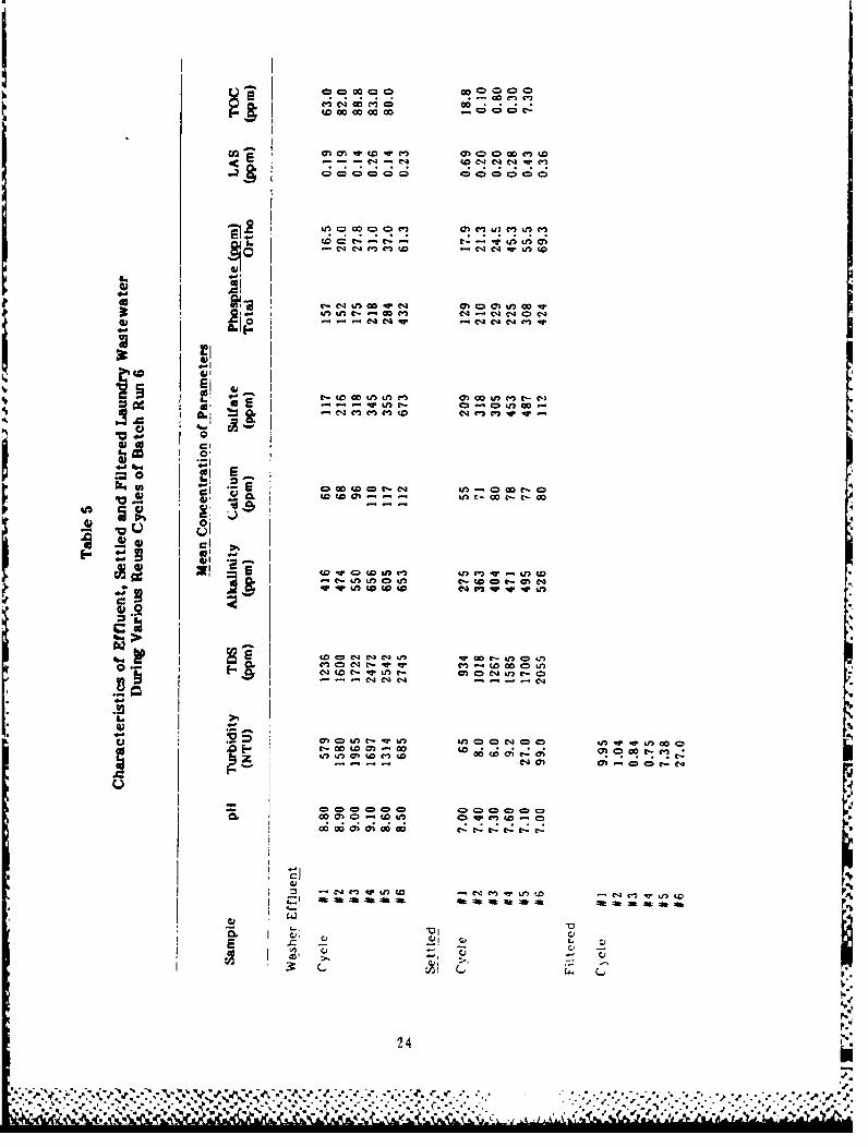
Characteristics of Washer Effluent and of Settled and FilteredWastewater During Various Reuse Cycles of Batch Run 6 24
6 Turbidity of Settled and Filtered Waters During Batch Run 6 47
7 Mean Concentration of Selected Inorganics by Reuse Cycle
for Settled Water During Batch Run 5 48
8 Mean Concentration of Selecti-d Inorganics by Reuse Cyclefor Settled Water During Batc.4 i Run 6 49
9 Characteristics of Laundry Wastewater 60
10 Chemical Compounds Causing Dermal Sensitization 62
Al Job Task Analysis Summary
A2 Job Data Worksheet
FIGURES
I Test Setup 12
2 Arrangement of Washing Machine, Water Heater, and FreshwaterTank in the Test Setup 13
3 Laundry Wastewater Collection Tank Used in the Test Setup 14
4 Laundry Wastewater Treatment Units Used in the Test Setup 15
5 Comparison of Mean Aikalinity Concentration in WasherEffluent and Treated Settled Waters During Various ReuseCycles of Batch Run 5 25
6 Comparison of Mean Total Dissolved Solids Concentrationin Washer Effluent and Treated Settled Waters DuringVarious Reuse Cycles of Batch Run 5 26
6
. e"......."..................................-......%-*%*%-" ** ., %
** ° -.. ". *.. . % ,... ". o.%. .*.
i " ( "" I ~~~~~~~~~~~~~~~~~~.. . ........ ....................."1 ° '
1" " " "1" °
" " """° " "' """I I "..... .

FIGURES (Cont'd)
Number Page
7 Comparison of Mean Calcium Hardness Concentration in WasherEffluent and Treated Settled Waters During Various ReuseCycles of Batch Run 5 27
8 Comparison of Mean LAS Concentration in Washer Effluentand Treated Settled Waters During Various Reuse Cyclesof Batch Run 5 28
9 Comparison of Mean Total Phosphate Concentration in WasherEffluent and Treated Settled Waters During Various ReuseCycles of Batch Run 5 29
10 Comparison of Mean Orthophosphate Concentration in WasherEffluent and Treated Settled Waters During Various ReuseCycles of Batch Run 5 30
11 Comparison of Mean TOC Concentration in Washer Effluentand Treated Settled Waters During Various Reuse Cyclesof Batch Run 5 31
12 Comparison of Mean Sulfate Concentration in WasherEffluent and Treated Settled Waters During Various ReuseCycles of Batch Run 5 32
13 Comparison of Mean pH in Washer Effluent and TreatedSettled Waters During Various Reuse Cycles of Batch Run 5 33
14 Comparison of Mean Turbidity in Washer Effluent and TreatedSettled and Filtered Waters During Various Reuse Cyclesof Batch Run 5 34
15 Comparison of Mean Alkalinity Concentration in WasherEffluent and Treated Settled Waters During Various ReuseCycles of Batch Run 6 35
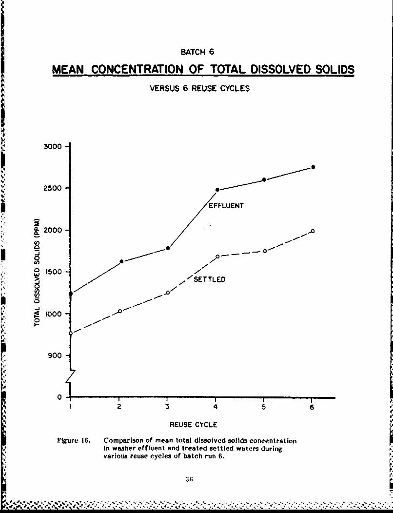
16 Comparison of Mean Total Dissolved Solids Concentrationin Washer Effluent and Treated Settled Waters DuringVarious Reuse Cycles of Batch Run 6 36
17 Comparison of Mear, Calcium Hardness Concentration inWasher Effluent and Treated Settled Waters During VariousReuse Cycles of Batch Run 6 37
18 Comparison of Mean LAS Concentration in Washer Effluentand Treated Settled Waters During Various Reuse Cyclesof Batch Run 6 38
19 Comparison of Mean Total Phosphate Concentration in WasherEffluent and Treated Settled Waters During Various ReuseCycles of Batch Run 6 39
7
"'" " ' " "" " '"-" '"" -"-',","''"-". 't'Y' .".:'''."-"-' -v" "'"--'% -''- - ."-'.-.- °." "."- .-. '.P.'

FIGURES (Cont'd)
Number Page
20 Comparison of Mean Orthophosphate Concentration In WasherEffluent and Treated Settled Waters During Various ReuseCycles of Batch Run 6 40
21 Comparison of Mean TOC Concentration in Washer Effluentand Treated Settled Waters During Various Reuse Cyclesof Batch Run 6 41
22 Comparison of Mean Sulfate Concentration in Washer Effluentand Treated Settled Waters During Various Reuse Cyclesof Batch Run 6 42
23 Comparison of Mean pH in Washer Effluent and TreatedSettled Waters Durir- Various Reuse Cycles of Batch Run 6 43
24 Comparison of Mean Turbidity ir Washer Effluent and of TreatedSettled and Filtered Waters During Various Reuse Cyclesof Batch Run 6 44
25 Comparison of Occurrences of Significant Difference BetweenWasher Effluent and Treated Settled Waters During VariousParameters 45
26 Laundry Wastewater Appearance During Various Stages ofRecycling 50
27 Schematic of Field Laundry Wastewater Recycling System 52
8
.,-. '.' ... .' .. .-.- .".- . . ,, -. " " ." j',j".p. ,.' .,. .". . .. . .. .' ", .. . .. / . . . - o . ... -. . .. . . .. " '. -p,,',% ',4 ,' . r-# ,," /" '' # 's -# .'-4 " .,.' ,",: .' ',/.. ,.' '. ., *,'. .
"-, : '',' ,-.: '',: .'-.-.''. '.''. .'- * -

DEVELOPMENT OF A FIELD LAUNDRYWASTEWATER RECYCLING SYSTEM
1 INTRODUCTION
Background
Since World War 1, fresh water supplies have been relatively abundant in areaswhere the U.S. Army has conducted military operations. Thus, little attention has beengiven to availability of water supplies or water sources, and especially to the need toregulate water use in the field. Recently, however, the Army has directed moreattention to water resource management due to the increased logistics costs of supplyingand transporting water to combat areas and the growing prospect that it may have todeploy forces to the Middle East or other arid regions. Water conservation, recycling,and reuse are some of the water resource management options being examined.
Water supply and distribution are expected tc be a major logistics effort in mostwater-short or water-critical areas of the world. Laundry operations are large users ofwater that could benefit from water management techniques. For example, one sectionof an Army field laundry (two washers and driers) operating 20 hours requires 10,000 gal*of water per day. However, a laundry wastewater recycling process can potentially save
" thousands of gallons of water per day for each field laundry unit and, at the same time,minimize the amount of wastewater discharged into the environment.
In 1975, the Army began developing a field laundry wastewater treatment kit (not
in Air Force inventory) to remove pollutants from laundry wastewater (detergents, oils,etc.) before it is discharged to the ground or released to streams or lakes. The treatmentinvolves a batch process in which anionic and cationic polymers, along with powderedactivated carbon, are added manually to each 500 gal of collected wastewater. Theresulting treated water can be further treated (polished) using a diatomaceous filter anddisinfected with chlorine for reuse for laundry pur;oses.
To use this treatment process in a field laundry wastewater recycling system(FLWRS) in field operatioas, the Army must first conduct a full-scale evaluation toverify the effectiveness of the treatment process and equipment.
Objectives
The objectives of this study were to:
1. Determine the effectiveness of the FLWRS to produce water meeting U.S. ArmyOffice of the Surgeon General (OTSG) interim quality criteria for direct reuse ofreclaimed wastewater in military field laundries
4'e
2. Develop an appropriate training program for military personnel who will operatethe proposed laundry wastewater recycling system
*Metric conversion factors are provided on p 64. b
9

3. Identify essential analytical tests and equipment required by system operators inthe field
4. Assess the potential health implications of the proposed system for recyclinglaundry wastewater.
Approach
The FLWRS was tested to verify its effectiveness in treating laundry wastewatersfor reuse and the data analyzed.
A suggested program of instruction for military operators was then developed basedon a "Task and Skill Analysis"' of the deployment, operation, disassembly and repackingof the proposed hardware system. Based on the laboratory results, tests and testingequipment required during field deployment of the system were identified.
Potential health hazards associated with field use of the system were determinedbased on a review of literature dealing with health implications of the chemicalsexpected to occur in typical field laundry wastewaters.
Scope
The information in this report represents only the initial stages in the developmentof a field laundry wastewater recycling system. Additional work is under way to furtherconfirm the safety of the concept, and field testing will determine whether the system,as currently configured, can be operated successfully by laundry unit personnel.
Mode of Technology Transfer
It is recommended that following completion of the development, procurement, andtesting of the FLWRS, existing Field Manuals pertaining to laundry be amended or a newmanual developed to include guidance in the use of this wastewater renovationequipment.
'Army Regulation (AR) 611-101, Commi.sioned Officer Specialty Classification Sy'ster(Department of the Army [DAI, 30 October 1984); AR 611-112, Manual of WarrantOfficer Military Occupational Specialities (DA, 30 October 1984); AR 611-201, Enlisted
Career Management Fields and Military Occupational Specialties ()A, 10 June 1984).
10rp.

2 TESTING SETUP AND PROCEDURES
The treatment protocol consisted of a batch process employing the manual additionof anionic and cationic polymers along with powdered activated carbon to each 500 gal ofcollected wastewater. The tests were designed to veLtfy the effectiveness of thewastewater renovation process and of the equipment identified 2 as being suitable for usein field laundry operations. Pollutants were removed by flocculation, settling, and theadsorption of organic substances by the activated carbon. The water was then treated(polished) using a diatomaceous filter and disinfected with chlorine.
Samples from laundry discharge (washer effulent), initially treated (settled), andfiltered waters were analyzed by standard testing methods to determine theeffectiveness of the treatment system. Although the water quality criteria prescribed byOTSG set limits on only turbidity, pH, and chlorine residual, a more comprehensive arrayof parameters was evaluated.
Equipment and Assembly
Figure 1 shows the test setup used at the research laboratory of the CivilEngineering Department at the Virginia Military Institute (VMI), Lexington, VA, wherethe testing was conducted.
el
Several variations from normal field laundry operations were made toaccommodate the lack of a standard-issue, trailer-mounted M-532 Laundry Unit and toconduct the testing in a laboratory setting. A commercial/industrial, front-loadingwasher/extractor of 70-lb capcity and a 42-gai electric hot water heater were used inlieu of the M-532 Laundry Unit. Also, commercial electric power was used to operatethe washer/extractor and pumps instead of the gasoline-engine-driven, 3 -kW portablegenerator, which is a standard component of a field laundry set. Rigid tanks and pipingwere substituted for collapsible tanks and hoses. None of these substitutions adverselyaffected treatment system operations or test program results.
Test Equipment Description and Functions
The following sections describe the equipment used for the tests, excluding pipes, ';fittings, and pumps.
Fresh Water Tank (FWT)
The FWT was a 500-gal-capacity cylindrical metal tank without a cover. The tankwas used to temporarily store water used for laundering clothes. The first 500 gal of
fresh water and subsequent makeup water were obtained from the municipal water line inthe laboratory. This tank held treated wastewater befoic it was recycled for washingsubsequent loads of clothing (Figures I and 2).
I.o
7 J. M. Morgan et al., Mathematical Modeling for Evaluation of Field Water SupplyAlternatives (Arid and Semi-Arid Regions) (VMI Research Laboratory, January 1981).
rr"-'-'~~~~~~~~~~~~~~. ..-" ..-......- %--.-,o • •.. ... •. .. .-.-....... . -.......
w" . .. ... .. .. .*" "' ,',, . % . •" , ", . .- ." .f% 4"°
.. /...%- . . " _ - °.o " .. , " , * " - . ,

Is Cwox :E
>J 0
gC
2
2 ci
ozJ
0 A
I.. A~
x x 1

WATER HEATER
FRESHWATER TANK WASHING MACHINE
(FWT)
Figure 2. Arrangement of washing machine, water heater, and freshwater tank in thetest shop.
Water Heater
The electric, 4500-W water heater was a Southern States glass-lined heater with a42-gal capacity. Stored washwater from the FW'r was pumped through the heater to thewashing machine at 160OF (Figures I and 2).
* 1Was~hing Machine
A single front-loading co mmerc ial/i ndustrial -type front-loading washer/extraotor
of 7,O-lb capacity was used (Figures I and 2). The wasihing machine discharged bothwashwater and rinsewater into a collection tank (CT') by gravity through a pipe dischnrgelino. The FWT, electrie water heater, and washing were located on an upper laboratorvloevel about 15 ft a0ove the lower levfel where the remaining equipment was located (see
* Figures I and 2).
1:6
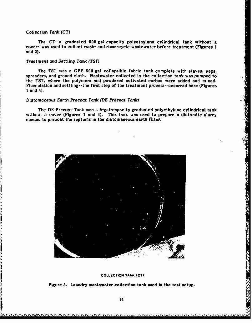
Collection Tank (CT)
The CT--a graduated 500-gal-capacity polyethylene cylindrical tank without acover--was used to colect wash- and rinse-cycle wastewater before treatment (Figures 1and 3).
Treatment and Settling Tank (TST)
The TST was a GFE 500-gal collapsible fabric tank complete with staves, pegs,spreaders, and ground cloth. Wastewater collected in the collection tank was pumped tothe TST, where the polymers and powdered activated carbon were added and mixed.Flocculation and settling--the first step of the treatment process--occurred here (FiguresI and 4).
Diatomaceous Earth Precoat Tank (DE Precoat Tank)
The DE Precoat Tank was a 5-gal-capacity graduated polyethylene cylindrical tankwithout a cover (Figures I and 4). This tank was used to prepare a diatomite slurryneeded to precoat the septums in the diatomaceous earth filter.
II
6
If
Sx
COLLECTION TANK (CT)
Figure 3. Laundry wastewater collection tank used in the test setup.
14
..*,. dt r '. w- ('s " frs r I ,* W % a ' ..d ' e t A* .4-' q, 'a . , l..q' f ' q.,.q"
*#* " *- '. /' ,pa•4q *S * .' % % % q

DIATOMACEOUSEARTH FILTER (DE)
COATING TANKTREATMENT & SETTLING
* TANK (TST)
Figure 4. Laundry wastewater treatment units used in the test setup.
I LDiatomaceous Earth Filter (DEF Filter)
The 420--gph DE filter was part of the 420-gph Water Purification Set
(E R 1)1,ATlE R). It was equipped with an integral 110-V, electrically driven pump andP4 provided the second step in the treatment process (Figures I and 4).
Holding Tank (Hr)
'rhe lIT was a 250-gal-capavity graduated polyethylene cylindrical tank without acover. It was used to collect the filtered water produced by the I)E filter. Calcium
F%.
0-% hvpochioritc is added rnanua!ly to disinfect the water for reuse in subsequent washingcnc rat:orn.

Clothes Washing Operations
The front-loading washing machine was hand-loaded with about 60 lb of soiled,standard Army-issue fatigues and miscellaneous items such as underwear and bed linen.The clothes were soiled manually since the same 60-lb load of fatigue uniforms wasreused for each wash cycle. Finely graded dirt was transferred to the clothing bydragging each uniform lightly across a container filled with dirt. Also, 50 mL of unusedengine oil was poured randomly onto the clothing before each load was placed in thewasher. Two ounces of detergent were placed in the washer detergent box, valve V-4*was turned to the hot/cold position, and the washer was started. With pump P-Ioperating, a 5-minute washing period was begun. Upon completion of the washing period,valve V-4 was closed, pump P-I was turned off, and the washer was drained for 5minutes. One ounce of detergent was placed in the detergent box, and the 10-minuteprocedure was repeated. After the second wash and extraction period, valve V-4 wasturned to the hot/cold mix position, pump P-i was turned on, and the washload was rinsedfor 2 minutes. Valve V-4 was closed, pump P-i was turned off, and the washer wasdrained for 5 minutes. After complete extraction, this 7-minute procedure wasrepeated. The wastewater effluent flowed by gravity into the CT when valve V-5A wasopened. These procedures for washing one load of clothes comprised one wash cycle.About 13 wash cycles were needed to fill the CT with a single 500-gal batch of laundrywastewater.
After the CT was filled to the 500-gal level, the wastewater was mixed vigorouslywith a paddle; 16 samples in 50-mL biochemical oxygen demand (BOD) bottles were thentaken. The samples were divided into fractions for replicate testing of chemical andphysical constituents.
Wastewater Treatment Operations
After each washing cycle and prior to treatment, jar tests were performed todetermine the amount of powdered carbon to be added to the wastewater. (Activated
carbon adsorbs organic substances. The polymers cause colloidal particles to clump andsettle to the bottom of the tank.) However, the validity of these tests was questionablebecause of the difficulty in measuring the small amounts of Type I and If Polymer thatalso had to be added to each sample.
Upon completion of water transfer from CT to TST, powdered HYDRODARCO
activated carbon was added to the TST. By closing valve V-5A and operating pump P-2,
the wastewater was recirculated for 20 minutes to mix it thoroughly. After thepowdered activated carbon was mixed, 75 mL of Type I Polymer (CAT-FLOC) was dilutedwith 750 mL of fresh water, half of which was added to I gal of TST water to provide apolymer solution; the polymer solution was then added to the TST. This step wasrepeated for the remaining Type I Polymer solution. The contents of the tank werestirred with a paddle at 3- to 5-minute intervals for the next 30 minutes.
During this time interval, two 1000-mL beakers were filled with fresh water; 1/2 gof Type If Polymer was added to each beaker (sprinkled to avoid clumping) and frequentlyagitated to mix the polymer thoroughly. The Type II Polymer solution was then added tothe TST and the contents of the tank stirred with a paddle for about 5 minutes, or untillarge floe appeared. The contents of the TST were allowed to settle for 20 minutes.
*The valves and pumps described in this section are shown in Figure 1.
16

Then, 16 water samples were taken from the TST using 500-mL BOD bottles and dividedinto fractions for analysis.
The next step of the treatment process involved adding 0.8 lb of diatomite aspreccat on the DE filter and filtering the supernatant in the TST. The DE slurry wasthen pumped into the DE filter using pump P-3 which is integral to the filter. Thisprocedure required valve V-7 to be closed and valve V-8 to be open. The slurry wasrecirculated for about 5 minutes to fully cost the septums in the DE filter. Valves werethen reset (V-7 to open, V-8 to close, and the three-way valve on the DE filter tofilter). To avoid pumping the sludge in the bottom of the TST, a 90-degree elbow wasattached to the end of the 1-1/2-in, tank discharge line, and the decrease in the tank'swater level was observed to avoid overpumping.
The filtered discharge from the DE filter was collected in the 500-gal HT. After
200 to 300 gal were filtered, two samples were collected in 500-mL BOD bottles forchemical analysis and 500-mL samples were taken for turbidity analysis after about 400gal were filtered. At the midpoint of tne filtering process, a 4-oz sample of filtrate wascollected in a NASCO sodium thiosulfate Whirl-Pak bag for testing total organic carbon(TOC) and fecal coliform levels.
Recycling Procedure IThe treatment process outlined above describes a typical cycle in the treatment of
500 gal or a "batch" of laundry wasterwater. Table 1 summarizes the details of thetreatment given each recyling sequence within a batch.
Data reported in Table I cover only Batches 4, 5, and 6, each of which varied in thenumber of cycles conducted. Batches 1, 2, and 3 were used to establish the test protocol,debug the test facility, and train the operators; consequently, no meaningful data weredeveloped from them.
Several adjustments were made to the basic operating procedure during the testingto improve the treatment procedure's efficiency. These adjustments are reflected inTable 1 and are discussed below.
Batch 4 treatment was begun (cycle 1) by adding soda ash in accordance withinstructions accompanying the Laundry Wastewater Pollution Abatement Kit. However,jar tests revealed floc would not form using Types I and II Polymer because of highalkalinity. Therefore, 500 mL of acid were added to lower the wasterwater's pH. Theoptimum pH level for floe formation was between 6.5 and 7.5. It was determined that100 mL of acid had to be added before subsequent treatment cycles to adjust the pH to Vthe required range. t.,
S.''
The number of times that the DR filter had to be backwashed varied due to diffi-cultics in filtering the supernatant in the TST. The DE filter pump's suction line wasattached to the side of the TST near the base of the tank. Settled solids were carried Iover into the DE filter, causing it to clog quickly. This condition was corrected when a90-deg:-ee elbow was installed on the end of the suction line to raise the intake above thedeposited solids level. The same filter clogging was observed when insufficient time wasallowcd for optimum settlement to oetur. This problem was reduced as the operators be-came more aware of sludge pickup by the filter pump. A noticeable reduction in thenumber of backwashes occurred as the testing progressed through Batch 5 and intoBatch 6.
17ab,
io
= ... ° •."..o.".*..... oo....•. . o. . -.. . . . •............o. =..... ,
• A I I I l!

- ) - CD co
4= C Un-4 40 coto C e-
-4
Ci C
Co #nO
C C) (Nn -4
- = Lf -4 4) co
40 4 W2 e-q in 00 0
-" 40 C
'en en I e-4 ) o
of CD) an -4C) G
en C en ien Go -n
-4 (0
C44 e* n Go
00~ ~ 4 C ni n00e
4.)
'en CD l q U G40 CD eni
CD in - C? c
$A C) 4
en en Go
in C;
z z
-V4 -t a 1
4)4) -E
18
%*. ** '. .. .. % .~.%~* %*...u...... *, * ***.'~~~L 4k. Id ,, *t I.* .:~~-. .. *

To obtain the most cost-effective use of chemicals, the amount of powdered carbonused during Batch 6 was reduced. The effects of this effort are reflected in the data forcycles 3 through 6.
Sampling and Analysis
The interim water quality criteria prescribed for recycled laundry water by theOTSG cover only the four parameters listed in Table 2. These and other parameters wereevaluated for this test program to identify the most common chemical constituents ofeach.
During each cycle, test samples were taken for complete analysis from both theraw laundry wastewater and filtrate to determine the effectiveness of the treatmentprocess. The following tests were made using the standard procedures as described;
1. Alkalinity: methyl orange indicator method.
2. Total Dissolved Solids (TDS): weight of the amount of oven-dried residue.
3. Calcium Hardness: a calcium indicator and potassium hydroxide, with Hach'sHexaVer solution as titrant.
4. Linear Alkyl Sulfates (LAS): crystal violet method, along with the Hach DR 3meter.
5. Tota! Phosphate: persulfate digestion method.
6. Orthophosphate: amino acid method.
Table 2
Interim Water Quality Standardfor Direct Reuse of Laundry Wastewater*
Parameter Limits
pH 6.5 to 7.5
Turbidity < 1 turbidity unit desirableA <5 turbidity units permissible
Free Available Chlorine 5 mg/L > 20 0 C10 mg/L < 200 C
Soap Hardness Adequate detergency
*SoDurce--Department of the Army, Office of the Surgeon General.
19*."
" .. 4. . ° °- 4. . .- 4 *. o \.*• 4 '.. , -... . ..'.:.L- -. ? :...:' --. ,"- .. :, -, V -,- .. .*...- .- ..'-,-... ...- ' ..-.. ... . ... .:-€ .-.. , . :

7. Total Organic Carbon (TOC): Beckman Total Organic Carbon Analyzer, Model
915.
8. Sulfate: turbidimetric method using the Hach SulfaVer 4 Sulfate Reagent.
9. Turbidity: Hach Laboratory Turbidimeter.
10. pH: Photovolt pH meter. (The meter was standardized several times each workday with pH buffer).
11. Total Hardness: EDTA titrimetric method, using Eriochrome Black T asindicator, Hach Standard HexaVer as titrant, and ammonium hydroxide solution as buffer.
20
/..
20
• ° m , • # ° " " ° . . ,-- . . . -. . . . . . . .o °, • o--. . • . • * *...-

3 RESULTS OF THE BATCH OPERATIONS
Six batch runs were made during the test program, with each batch subjected to a
different number of reuse cycles. Batches 1, 2, and 3 were trial runs used to provide
experience with the experimental setup and familiarize project personnel with the
equipment and procedures. Data obtained from batch runs 4, 5, and 6 were used to
analyze the wastewater recycling system's effectiveness.
Tables 3, 4, and 5 provide the results of batch runs 4, 5, and 6, respectively. The
tables present characteristics of washer effluent and of spttled and filtered laundry
wastewater during various reuse cycles. The results represent mean values of up to four
replicate analyses for each parameter.
Figures 5 through 13 and 15 through 23 present the variations in mean concentra-
tions of water quality parameters during batch runs 5 and 6, respectively. These figures
compare the variation of wastewater effluent and settled water quality parameters
during the reuse cycles. Figures 14 and 24 show variations of mean turbidity of filtered
water, compared to the washer effluent and settled water for batch runs 5 and 6,
respectively.
Figure 25 gives the percentage of occurrences when there was a significant
difference (p < 0.01) between the means of measured parameters in the laundry effluent
and settled waters. The information provided identifies (1) when the parameter
measured in the effluent exceeded that measured in the settled water for a given cycle,
(2) when the parameter measured in the settled water exceeded that in the effluent, and
(3) when there was no significant difference between the two parameters.
.1
.4..
.4
*,
21

40 CD~ O 40
19 C'4 W! -j !
t- C0D w--
* V2
C6
0 -t- qrV-C
0-3 ImC U o M0)
ul CDL
CD "M co CDC U
C. V:t.
on.l04 ac f~ .* 0-3MI (0acgZ
riC
izV
22.

ule O! .I O" CflO C 9 c 'mC.
w - = W) 4 -m ,3 c c -- - 4 c-
0O ~ C Go (D c 00
i C4C C l
4' C
to aAg Iz *-W w C)(DCO4=
C4 CEl v) ) C 0
-- W Mi0 U'2 t-1n- CI
E- Ir . J m ~ #Z0 C-V ocILI
, ).~
#3,
o23
4)S
S** **' * * .. *~..4, -~ ,.iA% .%'. ,~:...r.~~E
ccI c~o cooGo 0 0C
C" 0 0-0tcW 0 -5 t
Q Q' C)J CD C>
Go I ~ )e Y mU 1CZ t- t-lli0
o QC .a l ru t
C - &M0 cC=C"Ul c
U11 LnC £I c l -c3 4C:14 C1
0r00 000 L 00
'o C, e24
2, !E *: II .n t- c9n 4

BATCH 5
MEAN CONCENTRATION OF ALKALINITYVERSUS 8 REUSE CYCLES
iI700
44
600-
=--. 0 1000/",o
0~
400 /N
//
-- -o
1 2 4 5 6 78
- REUSE CYCLE
SFigure 5. Comparison of mean alkalinity concentration in washer
effluent and treated settled waters during various reuse," cycles of batch run 5.
400
I~ 'e L ~ i e j e 6 B - 4" . . . . . " • . . . . .. . .
. .23..56 i8 ' ' " " " '"

BATCH 5
MEAN CONCENTRATION OF TOTAL DISSOLVED SOLIDSVERSJS 8 REUSE CYCLES
2500 EFUN
* 2000
* i SETTLED~
00
500
0-I2 3 4 5 6 7 8
REUSE CYCLE
Figure 6. Comparison of mean total dissolved solids concentration inwasher effluent and treated settled waters during variousreuse cycles of batch run 5.

IBATCH 5
MEAN CONCENTRATION OF CALCIUM HARDNESSVERSUS 8 REUSE CYCLES
150-
EFFLUENT
0..
S / SETTLED
4 5 6
REUSE CYCLE
Figure 7. Comparison of mean calcium hardness concentration in washereffluent and treated settled waters during various reusecycles of batch run 5.
27
' ' " ' ' """; """ " '" " ;"","" "" ," - ' ." " ". 1. ... . - . .. ..".":'-'

BATCH 5 1
MEAN CONCENTRATION OF LASVERSUS 8 REUSE CYCLES
0.50
0.45
0.401
4 0.35-
0.304-
025 SETTLED/-
0.20-
0.105.41EFFLUENT
0.10-
0.05-
0.00~
1 2 3 4 5 6 78REUSE CYCLE
Figure 8. Comparison of mean LAS concentration in washer effluentand treated settled waters during various reuse cyclesof batch run 5.
28
%U

IBATCH 5
MEAN CONCENTRATION OF TOTAL PHOSPHATE
VERSUS 8 REUSE CYCLES
A
500
4501
400
350-So 1 ./
0. EFFLUENT/300 //I ..
"250/
* 200 " // / N N~ / SETTLED
/SO
:-_:, ~1o I" ' •II100
00
'..I2 3 4 5 6 78REUSE CYCLE
Figure 9. Comparison of mean total phosphate concentration in washer Ieffluent and treated settled waters during various reusecycles of batch run 5.
29
,..,4 , n i* " I '°, i :" u. . " i ' <'

BATCH 5
MEAN CONCENTRATION OF ORTHOPHOSPHATEVERSUS 8 REUSE CYCLES
Io8
/0! SETTLED
=-eo
70 EFFLUENT
600
I30-
S
I0-
P44
00
12 3 4 56 78 .. ,
REUSE CYCLE ''
Figure 10. Comparison of mean orthophosphate concentration In washer .effluent and treated settled waters during various reuse 0.cycles of batch run 5. ,.
•0 / 30

BATCH 5
MEAN CONCENTRATION OF TOTAL ORGANIC CARBONVERSUS 8 REUSE CYCLES
p
100
90-
S80 EFFL ENT
q 70a.
9 60 .
"'U ~ 50 -..
40
a 30-
230Leo'
202* 6
4 ,. ,
0- SETTLED !
I2 3 4 5 6 7 8
REUSE CYCLE
Figure 11. Comparison of mean TOC concentration In washer effluentand treated settled waters during various reuse cyclesof batch run 5.
31
-• 7\ -.;.:-~ ~*

BATCH 5
MEAN CONCENTRATION OF SULFATEVERSUS 8 REUSE CYCLES
1000
900-/Soo
200 /
100 /
600, / = I-
2 3 4 5 6 78
REUSE CYCLE
Figure 12. Comparison of' mean sulfate concentration In washer effluentand treated settled waters during various reuse cyclesof batch run 5.
32
, ,".". ',,,,_',_' ',,.,''500 /. / .""', ,"' , t.. "..-:,. .' '' ,'../ '-.".. ... '.,,..'-.,,.,-J%%,' "I , ' . _1 , ."bo ... ,..oo, 'o- '
. " 4o o , / v" v _ - . , . q . , o . . . .. " " , , " ' . % . . ' , ., ' * d ' * . , ' , . ? o =

BATCH S
MEAN pHVERSUS 8 REUSE CYCLES
10.0
90 ~.~J LUENT9.0
PH 18.0 -
100ooo-4ETTLED
7.0
2 3 4 5 6 7 8
REUSE CYCLE
Figure 13. Comparison of mean pH In washer effluent and treatedsettled waters during various reuse cycles of batch run 5.
33
., .,... ,. -, , ;,-,..O. .,, ....,.. . ..V

6ATCH 5
MEAN TURBIDITYVERSUS 8 REUSE CYCLES
2000
1500
EFFLUENT
1000
500
1 00
100-
... - - SETLED
5 FILTERED
I234 5 6 78REUSE CYCLE
Figure 14. Comparison of mean turbidity In washer effluent andtreated settled and filtered waters during various reusecycles of batch run 5.
34
-~~~ e. d

BATCH 6
MEAN CONCENTRATION OF ALKALINITY
I VERSUS 6 REUSE CYCLES6
700-
'S 650 I.
600 EFFLUENT~
550-
500-
- Z450:3SETTLED..-'
14 1-
400-
3 00-
d2 A 4
REUSE CYCLEjIFigure 15. Compfkrison of mean alkalinity concentration in washer
effluent and treated settled watersi during various reusecycles of batch run S.
.35
BATCH 6
MEAN CONCENTRATION OF TOTAL DISSOLVED SOLIDSVERSUS 6 REUSE CYCLES
3000
2500-
EFF LUENT
20100 --
1500"/" 'SETTLED
0
iU2
900
0 1 I 1 I... I I
I 2 3 4 5 6
REUSE CYCLE
Figurre 16. Comparison of mean total dissolved solids concentrationin washer effluent and treated settled waters duringvarious reuse cycles of batch run 6.
36

(BATCH 6)
MEAN CONCENTRATION OF CALCIUM HARDNESS
VERSUS 6 CYCLES
120
110-
100EFFLUENT
100i
80so.._.. _ o_ SETTLED .
70
//
S60
ST D
50
50
0 - I =I I 'II
,,2 3 4 5 6
REUSE CYCLES
Figure 17. Comparison of mean calcium hardness concentration in washereffluent and treated settled waters during various reusecycles of batch run 6.
37
. . . . * . .. ...- , *4 4-~ -. - * - * . F P ° . ° = % % • • " . " o .

BATCH 6
MEAN CONCENTRATION OF LAS
VERSUS 6 REUSE CYCLES
0.70-
0.60
0.50-
0.40 P~.SETTLED
4 ~0.40/
-0.30
CIle
, \0
o.0o EFFLUENT\0
0.10-
0.00I2 3 4 5 6
REUSE CYCLE
Figure 18. Comparison of mean LAS concentration In washer effluentand treated settled waters during various reuse cyclesof batch run 6.
38
- s.. o. EFFLU *.p'
v '4 * .. ~ * ... *.*Y..J.*. V~,\'O~

(BATCH 6)
MEAN CONCENTRATION OF PHOSPHATEVERSUS 6 REUSE CYCLES
500
U 450
400/
350 /2
W 300-1
SETTLED
4200
_, EFFLUENT150
100-
50-
0-2 3 4 5 6
REUSE CYCLE
Figure 19. Comparison of mean total phosphate concentration in washereffluent and treated settled waters during various reusecycles ofbatch run 6.
39

. . . . . . .-..--..-.. . -. . .. . .
(BATCH 6)
MEAN CONCENTRATION OF ORTHOPHOSPHATE
VERSUS 6 REUSE CYCLES
I00-
90-
80
70-"
a~60- / •
* W- 60 SETTLED,'"
S/ EFFLUENT//o 40I
30
1020[.'0
2 3 4 6
REUSE CYCLEsr .P.,p
Figure 20. Comparison of mean orthophosphate concentration in washereffluent and treated settled waters during various reusecycles of batch run 6.
40
° ,4A. " T *" ["" 1 '" "1" ***"*"'I *" 4"'" '. I'". . . ."-.-. . . ."-. .". ." "'. . . ." ". " ". ... . . ."

BATCH 6
MEAN CONCENTRATION OF TOTAL ORGANIC CARBON
VERSUS 6 REUSE CYCLES
100
90-
so ._
S 700.
, 4
0 o
250 -
* I0-
"-' \ SETTLED
3 4 6
REUSE CYCLE
SFigimre 2 1. Comparison of mean TOC concentration In washer effluent
' and treated settled waters during various reuse cycles
b . -.. of bath run 6.
)o -° 41
, .,

BATCH 6
MEAN CONCENTRATION OF SULFATEVERSUS 6 REUSE CYCLES
700
0650
600 EFFLUENT
550-
450 -
,,E "
500-
40 /\400- //
W 350 /
300 7j~0-~\SETTLED
250
200-
1500
100-
50
1 2 3 4 5 6
REUSE CYCLE
Figure 22. Comparison of mean sulfate concentration In washereffluent and treated settled waters during variousreuse cycles of batch run 6.
42
w'

BATCH 6
MEAN PH UNITS
VERSUS 6 REUSE CYCLES
9.0 ________________EFFLUENT
8.0
SETTLED
7 0 Nh
- -
PH
6.0
5.0
0.02 3 4 5 6
REUSE CYCLE
Figure 23. Comparison of mean pH In washer effluent and treatedsettled waters during various reuse cycles of batch run 8.
43

BATCH 6
MEAN TURBIDITY
VERSUS 6 REUSE CYCLES
2000
EFFLUENT
1500
1000
50
~\SETTLED
25 FILTERED
3 4 6
REUJSE CYCLE
Figure 24. Comparison of mean turbidity In washer effluent andtreated settled and filtered waters during various reusecycles of batch run 6.
r .- 44
ON aW.~~*. ~VV ~ *.e,'~.~q.. ag% ~*b

SIGNIFICANT DIFFERENCESBETWEEN PARAMETER MEANS
OF EFFLUENT AND SETTLED SAMPLES(Percentage of occurrences using all batche)
* jh 100%
. a 0%
-80%
O% -z 40%
lmZ
3U
j20%
Figure 25. Comparison of occurrences of slinifiant dif'ferene.. between washer effluent and treated settled waters
during various parameters.
45
W. STUEN t. TW TI. pc

4 DATA ANALYSIS
The following discussion analyzes the data presented in Chapter 3. A separateanalysis Is presented for each test batch (Batches 4, 5, and 6), with interpretationsprovided on trends noted in key test parameters.
Batch 4
As shown in Table 1, Batch 4 was recycled only three times; the specified carbon(6.5 lb) was added only in the first wastewater treatment cycle, but none was added forcycles 2 and 3. Acid was added for pH adjustment to form the floe needed for efficientsettling.
Table 3 shows that although a significant difference was observed for turbiditybetween effluent and settled and filtered waters, only in cycle 1 (when 6.5 lb of carbonwere added) did the filtered water meet the OTSG interim quality criteria for thisparameter. This shows that carbon addition for each cycle is essential; it provides therequired particles for beginning floe formation.
Batch 5
Table I shows that Batch 5 was recycled eight times, during which pH was adjustedwith 100 mL of acid; 6.5 lb of carbon were added each time a reuse cycle was treated.
All of the laundry water used is not recoverable, as noted by the amount of makeupwater required for each cycle (Table 1). The washed clothing retains some water thatcould not be removed during extraction. In wastewater treatment, the main loss ofwater is due to backwashing the DE filter. Although this filter is designed to use aminimum amount of water for backwash, the frequency of backwash produces cumulativewater losses and therefore increases makeup water requirements. In Batch 5, themakeup water was about 11 percent of the total required for eight cycles.
Table 4 shows that for eight cycles, filtered water turbidity met OTSG interimquality criteria seven times. Only. in the first cycle did the filtered water exceed theinterim criteria (11 vs. 5). Adding 100 mL of acid to each effluent for each cycleadjusted the pH to a range effective for floe formation although slightly exceeding theOTSG interim quality criteria.
Totul organic carbon measured for each of the eight cycles in the effluent andsettled waters showed a high degree of removal in each treatment cycle. In earh case,OTSG criteria were met (without chlorination), with the ranges of TOC values recordedbeing 62 to 87 partML per million (ppm) for the effluent water and 0.1 to 2.3 ppm for thesettled waters. figure 11 shows the mean concentrations of TOC for both the effluentand settled waters.
The treatment procedure followed for Batch 5 was very effective in meeting OTSGquality criteria. Additional reuse cycles could have been continued; however, because oftime and budget constraints and the requirement to study the effects of reduced carbondosage, the work was stopped after eight cycles.
, A

Batch 6
As shown in Table 1, Batch 6 was recycled six times, during which pH was adjustedwith 100 mL of acid; 6.5 lb of carbon were added only for cycles 1 and 2. To examine thefeasibility of reducing the amount of carbon added, it was reduced to 4.0 lb in cycle 3,2.0 lb in cycle 4, and eliminated for cycles 5 and 6.
The quantity of makeup water used in Batch 6 was about 7 percent of the totalamount of laundry water required for six washing cycles. The total amount of makeupwater was less than in the previous batch because the DE filter was backwashed lessfrequently per cycle. In several cycles, 500 gal of wastewater were filtered with onlyone charge of DE; i.e., the filter had to be backwashed once per tankful. This conditionrepresents effective coagulation and settling of the carbon slurries with a substantialsavings in diatomaceous earth. The efficiency of wastewater filtering improves whencarbon slurry settling improves. Resuspension of carbon sludge from previous cyclesdefinitely improves the settling characteristic of carbon/polymer slurry. Consequently,the first cycle of each batch was always the most difficult to filter.
OTSG criteria for turbidity of the filtered water were exceeded for cycle 1, metfor cycles 2, 3 and 4, and exceeded when no carbon was added in cycles 5 and 6. Table 6shows the observed turbidity values for the settled and filtered waters and the amount ofcarbon added for each cycle.
The OTSG interim quality criteria do not address TOC, but rather require thereclaimed water to carry a free available chlorine residual instead. The values reportedhere are those without any chlorination of the water and show the effectiveness of"organics" removal by the treatment system studied. Disinfection by adding chlorine isanother step in the treatment process and is very simple to do in the field.
TOC measured for each of the six cycles in the effluent and settled waters showeda high degree of "organics" removal in cycles 2, 3, and 4. For cycle 1, the removalefficiency was about 71 percent. For Batch 5, TOC removal in cycle 1 was 80.6 percent,while that shown for cycles 2 through 4 exceeded 99 percent in each case. For cycles 4and 5, removal efficiency was 90.8 percent. No TOC measurements were recorded forcycle 6. Figure 21 shows the mean concentrations of TOC for both the effluent andsettled waters.
Table 6Turbitity of Settled and Filtered Waters
During Batch Run 6
Turbidity {!NUQuantity of
Carbon Settled FilteredCycle Added (lb) Water Water
1 6.5 65 102 6.5 8 13 4.0 6 0.84 2.0 9 0.755 0 27 7.46 0 99 27
47 r-
. .... . .
:4.,j.,,.'.'. , .,',,', .. '. ,.'.-. , . -, .,,* ""..'.,~ ", ", d', - . • -".' . ~ . . . ". ". .. . . . . .* . -

Inorganic Constituents
Although the OTSG criteria do not address specific inorganic constituents (orcontaminants), this study examined selected inorganic parameters. The purpose was todetermine their change or buildup in concentration throughout the various reuse cycles,w!th the focus on settled rather than effluent waters. The rationale was to documenttheir impact as either an operational factor or a potential health-related concern. Sincethere are no measurement criteria or values, the data reported here are for documenta-tion and further review and evaluation by OTSG personnel.
Tables 7 and 8 show the measured means for seleeL3d inorganic constituents forBatches 5 and 6, indicating their respective trends. The following observations can bemade from the data:
1. Total dissolved solids increased steadily for the settled water at an approximaterate of 150 to 200 ppm per cycle for both Batches 5 and 6, with a total increase of about1585 ppm over e.ght cycles for Batch 5 and 1120 ppm over six cycles for Batch 6.
Table 7
Mean Concentration of Selected Inorganics by Reuse Cyclefor Settled Water During Batch Run 5
Concentration (mg/L)
Cycle 1 2 3 4 5 6 7 8
InorganicConstituent
Total DissolvedSolids 767 1005 1194 1509 1695 1795 2036 2351
TotalPhosphate 93 64 144 214 160 250 344 421
Ortho-Phosphate 12 16 20 37 54 53 63 75
Sulfate 180 249 403 450 619 142 670 883
48

Table 8
Mean Concentration of Selected lnorganies by Reuse Cyclefor Settled Water During Batch Run 6
Concentration (ppm)
Cycle 1 2 3 4 5 6
InorganicConstituent
Total DissolvedSolids 934 1018 1267 1585 1700 2055
TotalPhosphate 129 210 229 225 308 424
Ortho-Phosphate 18 21 25 45 56 69
Sulfate 209 318 305 453 487 112
2. Total phosphates for Batch 5 showed a steady Increase of about 330 ppm overthe eight cycles, with the Increment Increasing at each cycle, indicating a pattern ofmore rapid buildup. For Batch 6, a similar pattern was observed, except that theincrement between cycles when no carbon was added (5 and 6) tended to be greater herethan for similar cycles in Batch 5.
3. Orthophosphates tended to Increase regularly from cycle to cycle for bothBatches 5 and 6, with a total Increase of about 50 ppm for each.
4. Sulfates showed an increasing trend over each cycle for Batch 5, giving a totalIncrease of about 700 ppm over the eight cycles. Although the increasing tendency wassomewhat variable, a rough estimate would indicate an approximate gradient of 150 to200 ppm per cycle, given the treatment procedures followed In this batch. For Batch 6,the pattern was somewhat similar, except for cycle 6, which was an exception to theincreasing trend.
49 1

Wastewater Treatment Effectiveness
Figure 26 shows typical samples of laundry wastewater as it was processed throughthe various stages of the renovation process. Of particular note is the wide spectrum ofclarity (decrease in turbidity) obtained through the unit processes of coagulation (with pHadjustment if necessary), settling, and diatomaceous earth filtration. Turbidity levelsshown range from about 700 NTU in the effluent, 20 NTU in the settled water, and INTU in the filtered water. Therefore, the la .ndry wastewater recycling system--acoagulation/filtration batch treatment process--is a viable method of effectivelytreating laundry wastewater for recycle in laundry units. The system's simplicity ofequipment and treatment methodology make it operable by enlisted laundry specialistsafter minimal training.
Figure 26. Laundry wastewater appearance during various stages of recycling.
50
j, Pp

5 TRAINING PROGRAM
A preliminary program of instruction (POI) was developed based on the task andskill analysis of the proposed field version of the laundry wastewater recycling systemshown in Figure 27. Training conducted In accordance with the POI would be given toArmy enlisted personnel attending advanced individual training for MOS 57E--laundryspecialist. The PO may be adapted for use in training AFSC 611 XO personnel.
Task and Skill Analysis
Appendix A provides the Task and Skill Analysis performed in accordance withArmy regulations. This analysis indicates that two members of a laundry section, whichIs organic to the Field Service Company (General Support), would be required to deployand disassemble the FLWRS. However, only one enlisted person would be required tooperate the system properly during a normal 10-hour shift.
A typical Army laundry section consists of a section chief and 13 laundryspecialists (see Appendix B). This level of staffing permits a laundry to operate 20 hours(two 10-hour shifts) per day, 7 days per week. One laundry specialist is designated asdriver of the cargo truck and trailer assigned to the laundry section. The U.S. ArmyTraining and Doctrine Command must determine whether the driver and some othermembers of the Section can operate a FLWRS, or whether the section must beaugmented with additional personnel.
The Task and Skill Analysis (Appendix A) often refers to a hypothetical manual onthe operation and maintenance of the FLWRS. Such a document would be produced if theArmy approved use of the FLWRS.
Program of Instruction
Appendix C presents the suggested POI for laundry specialists. The primary focusof the instruction is the treatment procedure and water sampling and testing. Sixty-fivepercent of the total 40 hours indicated in the POI would be devoted to lead-throughpractical exercises to ensure proficiency in measuring the proper amounts of chernicePls,operation of the diatomaceous filter, and water sampling/testing procedures. Arelatively small amount of time would be allotted to system insta!lation and disassemblybecause students will already be familiar with much of the equipment.
51

ww
wi.
cr. a.cI,a CL'
- w
w 2 La
7W44
0~ A.(,
52

6 WATER QUALITY MONITORING
The wastewater treatment techniques designed for the FLWRS were tested in thelaboratory to validate their effectiveness. A comprehensive battery of tests wasperformed to evaluate water quality during treatment, although when a FLWRS isdeployed in the field, the operator need not conduct similar extensive water qualitytesting. Analysis of the laboratory test results readily revealed which tests could beperformed easily in the field, yet still provide sufficient data to determine systemviability.
System viability in the field depends on whether the treatment process is providingrecyclable water of appropriate quality. A field operator can determine water quality byperforming just four critical sampling and testing procedures: two pH measurements, aturbidity evaluation, and a residual chlorine measurement. Although care should betaken when taking these measurements, it is neither necessary nor possible to conductthese tests with laboratory precision in the field.
To supplement water quality results, an operator must also observe the treatmentprocess. The most critical area is periodically checking the amount of suds produced bythe laundry detergent during washing. The rate of settling after the polymers have beenadded to the wastewater must also be observed.
Water Sampling and Testing
The following describes the sampling and testing procedures to be performed by alaundry specialist when operating the FLWRS:
pH
Two separate pH measurements should be taken on each 500 gal of laundry
wastewater being treated. The first involves measuring and adjusting, if necessary, thewastewater pH to ensure that it is between 6.0 and 8.0 before starting the treatmentprocess. The second test is performed on the filtered water to ensure that its ph isbetween 6.5 and 7.5 before the water is reused for washing another load of clothes.
The first test on the 500 gal of wash- and rinsewater uses litmus paper. In most* cases, the colormetric reading will indicate an alkaline condition because of the dirt and
the body salts from perspiration on the clothing and the detergent in the washwaterdischarge. Under these conditions, the operator incrementally adds acid (e.g., sulfuricacid) to the tank to reduce the pH to a neutral range (6.0 to 8.0) where optimum floe is~formed once the polymers and carbon are added to the wastewater. However, if the pH
is less than 6.0, sodium carbonate is added to increase it. Upon startup, several pHreadings may be needed before the proper amount of acid can be determined; howev.r, asingle reading may only be needed thereafter to verify that conditions have not changed.
The second pH test on the filtered water uses a standard color comparator equippedwith pH discs. This is a more accurate method of measurement than litmus paper and ismore appropriate for testing clean, treated water, which must be in the range of 6.5 to7.5 to meet OTSG criteria.
-4
53
"- -w =1= " " "o % • % 1 %,-I=. A ,

Chlorine
Treated water must be adequately disinfected before bEing recycled through thelaundry unit. Calcium hypochlorite--a chemical already in the Army supply system--isused for this purpose.
Free residual chlorine is measured in the treated water storage tank after calciumhypochlorite h; added manually to the collection tank and after the chemical isthoroughly mixed with the water during the filling process. Chlorine tests are peformedusing a standard cu!or comparator equipped with chlorine discs and DPD* tablets.
Turbidity
Turbidity of the treated water should be measured to verify that it is Iess than 5NTU, as set forth in OTSG Interim Water Quality Criteria. A precise measurement is notrequired for the FLWRS; therefore, use of a simple turbidimeter to determine the•elative clarity of a water sample is recommended. Experience has shown that a soldierneeds only a little experience with this device to determine whether . 1000-mL sampleof water is iess or greater than 5 turbidity units.
Operational Monitoring
A laundry specialist should periodically observe the amr'-nt of suds in the washer toverify that enough detergent nas oten added. Low surdsing can also occur when thecalcium hardness level builds up after wahtewater has b.een recycled a number of times.When this happens, the operator of the FLWRI should be prepared to stop furtherrecycling and recharge this sy, tern with fresh water.
Settlement of suspended so iJs in the wastewater normally occurs quickly r.fter theaddition of activated carbon , rrj polymers. If it does not, the operator must decidewhether the washwater has been neutralized properly or whether the prescrbed amountsof each type of polymer have been added.
Water Quality Test .quipment
The Army has two Water Quality Analysis Sets (WQAS, not in Air Force
inventory)! one used by water purification unit operators, and the other by preventivemedicine teams. Thes sets, which consist of water test kits with necessary reagentchemicals, are packaged in rugged, watertight cases. Each set weighs about 55 Ib, has avolume of about 4.5 cu ft, and costs more than $1000.
The WQAS-Engineer** provides on-site information to deternine the type ofpurification equipment required, monitors the equipment operations, and detects watercontamination caused by chemical agents.
The main components of the WQAS are:
* Alkalinity test kit
*N, N-diethyl-p-phenylene dianmine.S*Used by operators of water purification units.
54

* Turbidity test kit
o Sulfate test kit
o pH chlorine/residual test kit
* Hardness test kit
* Color test kit
* Low-range chloride test kit
o Conductivity meter
* Water testing kit for chemical agents AN-M2
* Refill kit, chemical detector, V-G, ABC-M30
o Supporting labware and reagents
The WQAS-Preventive Medicine is designed for on-site monitoring of the quality ofraw water sources, wustewater effluents, and drinking water produced.
The main components of the set are:
" Acidity test kit
" High-range chloride test kit
" Iron test kit
• Dissolved oxygen test kit
* Zinc test kit
" Multi-purpose spectrophotometer
-- Fluoride
-- Nitrogen, ammonia
-- Ferrous iron
-- Ferric iron
The Belvoir Research and Development Center is developing water quality analysissets to replace the two described above. However, both the old and new sets containmore test kits and equipment than needed to monitor laundry wastewater recyclingoperations. In lieu of standard-issue WQAS, it is recommended that just the testequipment listed below be provided to the Laundry Section of a Field Service Company:
* Litmus (pH) paper, range 6.0 - 8.0
55
I"""......-.. *.... .. .q4- ""'%'~*m' q.

" Color comparator with pH and chlorine discs
" Turbidity tube
A special Water Quality Analysis Set made up of the above components should berelatively inexpensive (less than $100). More importantly, the simplicity of each itemwill enable a laundry specialist to learn quickly how to use them and develop confidenceIn his/her ability to control the recycling process.
56
NI

7 HEALTH IMPLICATIONS OF RECYCLING LAUNDRY WASTEWATER
There is very little published information describing either the expected occurrenceof specific chemicals in laundry wastewater or their related health effects. Generally,most of the available data 3 focus on criteria for generating potable water afterrecycling. Therefore, the related health effects information focuses on frequent oral ordirect dermal contact with recycled water. In the case of the FLWRS, such stringentdirect-contact criteria may not apply. The recycled and FLWRS-treated laundrywastewater will be used only for laundry. Direct general troop contact with the treatedwater (i.e., consumption or bathing) is neither intended nor likely to occur, except forindividual(s) operating the laundry facilities, who may have an increased risk of chemicalexposure. The following sections provide more specific discussions of the route(s) ofexposure and contaminants of concern.
Exposare
The primary health concern for a field unit using the FLWRS would be skin contactwith chemical deposits present on clothing or linens after laundering. Therefore, dermalcontact or absorption is the primary route of exposure. No information was available inthe literature about health hazards associated with anhydrous dermal contact withchemicals likely to occur as deposits after laundering; however, compounds that are skinirritants or cause skin sensitization are likely to be of greatest concern. One method forevaluating potential health effects would be skin patch tests using laundry wastewaterconcentrates dried onto fabric.
Contact with moisture could enhance skin irritability or absorption of chemicaldeposits. In the field, such contact could occur through perspiration, rain, immersion in alake or stream, or contact with wet ground. The moisture's pH may also greatly affectthe actual absorption or solubility of a given compound.
The hazard associated with any compound must be evaluated individually, based onits physical, chemical, and toxicological properties. Chemical interactions may alsooccur in laundry water that may result in additional compounds of higher risk beingdeposited. The synergistic effects of several compounds present at the same time mayalso affect an overall risk assessment.
Special Population at Risk
OperatorG of FLWRS facilities may have a different risk of chemical exposure thanthe general field unit population. They would potentially have direct contact with thelaundry water at all stages of treatment. However, use of protective gloves and bootswould minimize any potential hazard associated with such direct contact. Use ofprotective equipment would also prevent direct contact with the sulfuric acid used forpH adjustment during water treatment. In its concentrated form, this strong acid can
cause severe skin burns. Other water treatment chemicals do not have sim 'ar handlinghazards.
3Characterization Studies of Wastewater Generated from Military Installations,CALSPAN Report No. ND-5296-M-1 (CAI.SPAN, April 1973); Evaluation of HealthEffects Data on Reuse of Shower and Laundrv Waters by Field Army Units (WaldenDivision of ABCOR, April 1979). .
.57
-4. -... . . . . .,., ,,* . .* . , ..." " '-""" .% ". ""%* %'' * ' % *a t. % .'., % % • % % %% % % .O%% o . ,l,.*. . .
, i I I i I I I i I I I I " " "l" ' " ".4

Depending on the chemicals present in the laundry water during all phases of use ortreatment, any volatile organic chemicals would be of particular concern. Compoundswith a high vapor pressure or a high Henry's Law Constant would tend to leave the waterphase and enter the air. This vaporization is accentuated when the water is turbulent oragitated, such as when laundry wash- or rinsewater is transferred to the large holding ortreatment tank before coagulation or when mixing is done during coagulation. The riskof respiratory exposure depends entirely upon the nature of the chemicals present in thelaundry water and is directly related to the chemicals that appear in the soiled clothingor linens. It is unlikely that high vapor concentrations will occur. Operating the FLWRSin a well-ventilated or unenclosed area would tend to dissipate all but the densest vaporsand preclude the need for protective breathing devices. Again, the relative risk can onlybe determined with respect to specific compounds.
Chemical Content of Laundry Wastewater
The chemicals in recycled laundry wastewater consist mostly of those found insynthetic detergents, bleaches, and soaps. There is also potential added chem;cal inputfrom water treatment chemicals and various constituents present in soiled clothing orlinens. Previous studies have reported typical wastewater characteristics for variousmilitary installations.' The data In Table 9 summarize some chemical characteristicsmeasured for field laundry wastewaters compared to data for commercial laundrywastewater. It appears that the major difference between military and commerciallaundry wastewater is that both the pH and total alkalinity are lower for militaryeffluents.
When the FLWRS is used in the field, hospital laundry may be combined withgeneral laundry. This could add a few specific contaminants, such as blood,disinfectants, drugs, laboratory chemicals, and X-ray processing chemicals. 5 Specificcontaminants associated with these sources include mercury, barium, beryllium, boron,chromium, and lead. There are no data available indicating skin sensitivity to thesecontaminants; however, ingestion of most heavy metals produces adverse health effects.
Water Treatment Chemicals
The fo llowing chemicals, all of which are readily available commercially, are addedto laundry wastewater during water treatment:
* Polymer Type I, a cationic coagulant
* Polymer Type Ii, an anionic coagulant
* Sulfuric acid for pH adjustment
e Soda ash (anhydrous sodium carbonate) for pH adjustment
4Characterization Studies of Wastewater; J.T. Bandy, M. Messenger, and E. Smith, AProcedure for Evcluating Subpotable Water Reuse Potential at Army Fixed Facilities,Technical Report N-109/ADAllII91 (U.S. ,.Army Constru- -n Engineering ResearchLaboratory [USA-CERLI, 1981).
5Characterization of Studies of Wastewater; J. T. Bandy, M. Messenger, and E. Smith.
58
9-

Table 9
Characteristics of Laundry Wastewater(Adapted from Characterization Studies of Wastewater Generated from
Military Installations, CALSPAN Report No. ND-5296-M-1 [CALSPAN, April 19731).
Parameter Military Field Unit Commercial(mg/L except as noted) Ave. Max. Range
Turbidity, JTU* 1,362.7 3,800.0pH, Unit 7.4 7.6 9.0 to 10.3Total Dissolved Solids 500.0 800.0Suspended Solids - - 210 to 540Total Solids - 800 to 2,100Volatile Solids - - <1,500Detergent 2.8 6.5Total Phosphate 75.7 128.0Orthophosphate - 122.0Polyphosphate 6.0Sulphate 81.0 175.0Silicate 94.0 150.0Total Hardness (CaCO 3 ) 30.0 34.0Calcium Hardness (CaCO 3 ) 22.7 32.0Magnesium Hardness (CaCO3 ) 7.3 12.0Total Alkalinity (CaCO3 ) 227.0 286.0 <511Chloride 130.0 -BOD, 5-day 339.0 - 370 to 635TOC 100.2 258.0Oil and Grease - - 170 to 550
*Jackson Turbidity Unit.
* Powdered activated carbon to adsorb organic components
e Calcium hypochlorite to add chlorine for disinfection.
- No adverse health effects are anticipated to result from exposure to these items.,'. Both coagulant polymers are approved by the U.S. Environmental Protection Agency for k
use in drinking water systems. Their formulation and recommended doses do not produce* residuals or contaminants of concern to health safety. The use of sulfuric acid to adjust
pH will add sulfate to the wastewater. However, laboratory testing of the FLWRSindicated that the amount of sulfate does not approach unhealthful levels, so fieldoperators will not have to monitor this parameter. Similarly, any additions of soda ash to
.p adjust pH will increase the laundry wastewater's carbonate content, but this need not be_"'e measured in the field, since increasing hardness and low sudsing will reflect increases in
carbonates. Also, there is no information indicating that dermal exposure to sulfate orcarbonate deposits is hazardous.
59-x,
p, •+ o, •p , °, oo * . -•o

Powdered activated carbon, along with anything adsorbed to those particles, isremoved from the FLWRS-processed water by settlement and by the DE filtration. Thefield operating procedures Indicate that monitoring turbidity will provide an opportunityto detect any breakdown of the settling and filtering process. If there is inadequateclarification, the potential result would be increased skin irritation due to the carbonparticles trapped in laundered fabrics, or due to possible contact with organic compoundsadsorbed to the carbon particles. Additions of calcium hypochlorite are evaluated basedon field monitoring of chlorine levels. These data ensure that chlorine is maintainedwithin the range that provides antimicrobial activity, but does not present a healthhazard.
Contaminants Resulting From Field Activities
The most important factor influencing contamination and potential health hazardsIn recycled laundry water is the type of compounds occurring in soiled clothing andlinens. Those kinds of compounds relate directly to field activities. As soldiers carry outtheir duties, their clothing comes in contact with various compounds, which then appearin the laundry wastewater.
The following are examples of groups of chemicals that may contaminate recycledmilitary laundry water: 6
e Munitions
* Pesticides
* Oils and greases
* Solvents.
The extent to which any of these items affect the overall health safety of recyclinglaundry water depends on two main factors: the toxicological properties of the individualcompound, and the extent to which the compound appears in laundry wastewater. Forexample, few Individuals may contact large amounts of a given compound during theirdaily routines. However, this compound may be diluted out of a range of concern due tothe small proportion It contributes to overall laundry water content. In contrast, most ofthe troops may contact a small or moderate amount of a given compound. Because ofthe relative proportion, this compound may appear in the laundry wastewater at a levelof concern. Such factors should be considered when decisions to recycle laundrywastewater are being made. The supporting Field Surgeon should be able to evaluate therelative hazard associated with various activities. It is possible that before being addedto the general laundry, some clothing may require a preliminary rinse that will not berecycled.
It would require a significant effort to compile a comprehensive list of all potentialchemicals of concern when operating a FLWRS. The compounds listed in Table 10 areexamples of chemicals shown to cause dermal sensitization.7 Some of these compound3
'Personal Communication, Dr. Steven Schaub; U.S. Medical Bioengineering Research andDevelopment Laboratory, Fort Detrick, Maryland, November 13, 1984.Evaulation of Health Effects.
60
I ..

Table 10
Chemical Compounds Causing Dermal Sensitization
Compound$ Uses
Nickel Alloys such as stainless steel, alkaline
storage batteries, magnets
Protease Meat tenderizers, some detergents
Parabens Antimicrobials In food and drugs
Lanolin Ointments, soaps, sun lotions
Propylene glycol Antifreeze, solvents, hydraulic fluids,sun lotions, brake and deicing fluids,bactericide
Triethanolamine Dry cleaning, soaps, detergents, waterrepellent, softening agent
Sorbic acid Fungicide, food preservative
Hexachlorophene Germicidal soap, veterinary medicine
*Adapted from Evaluation of Health Effects Data on Reuse p? Shower and LaundryWaters by Field Army Units (Walden Division of ABCOR, April 1979).
**Adapted from The Condensed Chemical Dictionary, 10th ed. (G. G. Hawley, VanNostrand Reinhold Co., 1981)
also exhibit photosensitization; that is, following exposure to the compound, the skinbecomes more sensitive or irritated when exposed to bright sunlight.
It is anticipated that organic compounds would be adsorbed by the activated carbonand then removed by settling and DE filtration. Of the compounds listed in Table 10,nickel could pose a problem by leaching into laundry water from stainless steel piping,holding tanks, or other laundry equipment. However, the occurrence of nickel in militaryfield laundry water should be minimal because stainless steel components in laundryequipment are limited to the washer drum and are required to have an enamel coating.
Some concern has been expressed over potential health hazards caused byelorination of various chemicals likely to occur in laundry wastewater. Estimates have
been developed to predict the concentration of chlorinated byproducts resulting fromethanol, isopropyl alcohol, urea, lactic acid, triethanolamine, and propylene glycol.8 Ofthese, only the ethanol chlorination product--2-chloroethanol (or ethylene chlorohydrin)--appears to be a possible health hazard. The estimate requires >100 ppm ethanol and
8Evaluation of Health Effects. IN
61

predicts a maximum of 25 ppm for the resulting 2-chloroethanol. However, theformation of this hazardous compound is limited by chlorine (Cl ) concentration. The 2-chloroethanol is presented as a health hazard for several reasons:
# High inhalation toxicity--2 ppm for 1 hour was fatal to rats
* Rapid skin absorption of the compound in its pure form or from water solutions
9 Carcinogen analog to epichiorohydrin and/or vinyl chloride.
Even trace amounts of 2-chloroethanol, which is highly water-soluble andpenetrates ordinary rubber gloves and protective clothing, 10 may present a serious healthhazard. It Is reasonable to expect that any 2-chloroethanol generated in laundrywastewater will be removed by adsorption onto activated carbon; however, data to verifythis were not located.
Liquid ethanol would be unlikely to contact laundry water. This solvent is veryvolatile, and virtually all of the ethanol would vaporize before contacted clothing orlinens were laundered. Also, very little chlorine would be available to react with anyethanol remaining in treated laundry wastewater. Nevertheless, due to the healthdangers from 2-chloroethanol, medical authorities should be aware of potential problemsif liquid ethanol enters laundry water.''
9Evoluation of Health Effects."0 The Condensed Chemical Dictionary, 10th ed. (G. G. Hawley, Van Nostrand Reinhold
Co., 1981).'J. T. Bandy, M. Messenger, and E. Smith.
62

S COST ANALYSIS
A complete cost analysis of the FLWRS has not been produced at this time but willbe available in a future technical report. An approximate Indication of the value of thewater produced is drawn from Morgan et al., who worked with mathematical modelingfor evaluation of field water supply alternatives in arid and semiarid regions. They foundthe cost of water produced by a 600 gal per hour (gph) ROWPU (Reserve Osmosis WaterPurification Unit*) to be $20.36 per 1000 gallons. This cost included fuel, polymer,chlorine, acid, sodium hexametaphosphate, and filters. Following the same reasoning,the cost for treating 6000 gal of water with the FLWRS could be estimated at $8.63 per1000 gallons, Including the cost of soda ash, polymers, carbon, calcium hypochlorite,diatomaceous earth, and fuel. Neither analysis includes capital costs, labor, ortransportation and distribution. These figures indicate that the FLWRS is substantiallymore economical, producing 1000 gal of water for $11.73 less than the ROWPU.
The laundry section discussed in the introduction requiring 10,000 gallons of waterper day can be used as an example of the possible water savings. Field laundry recyclingis effective for at least three cycles. Recycling can be continued past that stage, buthardness increases and more detergent is necessary. There is also an approximate 10percent loss of water due to water left in clothing and from filter backwash. Therefore,about a 70 percent savings in water use is indicated, which translates into 7000 gal ofwater per day per laundry section. This is 7000 gal of water per day which would nothave to be supplied by the ROWPU and transported to the laundry, resulting in substan-tial savings in production cost and equipment utilization.
This savings in water when spread throughout a theater of operations can haveseveral benefits. Most importantly, more water would be available to accommodateadditional water users, either troops or equipment. Second, water transportationequipment would not be overtaxed, but could be freed for additional duty. Third, fuelconsumption would be reduced from 5 gal per 1000 gal of water produced to 0.5 gal,lessening the logistics problem and resulting in substantial savings of a vital commodity.
i[
*ROWPUs are the standard water purification device in the Army's Table of
Organization and Equipment.
L 63
*rf .L -'_ -4 V* A y '0i

9 CONCLUSIONS
The laundry wastewater recycling system--a coagulation/filtration batch treatmentprocess--is a viable method of effectively treating laundry wastewater for recycle inlaundry units. The system's simplicity of equipment and treatment methodology make itoperable by enlisted laundry specialists after minimal training. rhe guidance provided inthis report will be useful for Army and Air Force personnel who must effectively operateand maintain field laundry units using recycled laundry wastewater. The followingspecific conclusions were reached from the operational evaluation.
* The number of treatment cycles that may be performed on a batch of laundrywastewater is affected primarily by the hardness of source water. Consequently,recycling should be terminated when insufficient suds are produced after the properamount of detergent has been added for washing.
e The filterability of the settled wastewater in a cycle is the best indicator formaking changes, during subsequent cycles, to operating procedures such as carbondosage, duration of mixing, adjustment of pH, and settling time.
* The initial activated carbon dosage applied in the first two treatment cycles maybe reduced by about 50 percent when enough sludge is available for resuspension insubsequent cycles to improve the carbon's settling characteristics.
* A training course of about 40 hours has been developed that would allow alaundry specialist to become a proficient operator of a FLWRS.
* Relatively unsophisticated water sampling and water quality testing equipmentand procedures are required for a laundry specialist to control the wastewater treatmentprocess and produce adequate quality for recycling. Field testing can be limited tomeasurements of pH, free chlorine, and turbidity.
* An assessment showed that no health hazard is anticipated to result from the useof detergents, bleaches, soaps, and water treatment chemicals during the operation ofFLWRS. However, certain safety procedures must be observed to avoid personal injurywhen handling sulfuric acid and to avoid extended dermal contact with or ingestion oflaundry wastewater.
* Depending on the types of activities performed by troops in the field, theprimary source of potentially hazardous substances in recycled laundry waters isanticipated to be soiled clothing and linens.
METRIC CONVERSION FACTORS
1 gal = 3.785 L1 lb = .4535 kgI ft = .3048 m1 oz = 28.3495 g1 in. = 25.4 m rI cu ft .0283 mI psi = 6.895 kPa°C = (°F-32) (5/9)
64
q~~ ~ ~~~~ -J A' . . . . . - . - - -

CITED REFERENCES
Arny Regulation 611-101, Commissioned Officer Specialty Classification System(Department of the Army [DA], 30 October 1984).
Army Regulation 611-201, Enlisted Career Management Fields and Military OccupationalSpecialties (DA, 10 June 1984).
Army Regulation 611-112, Manual of Warrant Officer Military Occupa.ional Specialties(DA, 30 October 1984).
Bandy, J. T., M. Messenger, and E. Smith, A Procedure for Evaluating Subpotable WaterReuse Potential at Army Fixed Facilities, Technical Report N--109/ADA111191 (U.S.Army Construction Engineering Research Laboratory [USA-CERL], 1981).
Characterization Studies of Wastewater Generated from Military Installations,CALSPAN Report No. ND-5296-M-1 (CALSPAN, April 1973).
The Condensed Chemica! Dictionary, 10th ed. (G. G. Hawley, Van Nostrand Reinhold Co.,1981).
Evaluation of Health Effects Data on Reuse of Shower and Laundry Waters by FieldArmy Units (Walden Division of ABCOR, April 1979).
Morgan, J. M., et. al., Mathematical Modeling for Evaluation of Field Water SupplyAlternatives (Arid and Semi-Arid Regions) (VMI Research Laboratory, January 1981).
UNCITED REFERENCES
Operator and Organizational Maintenance Manual, Laundry Wastewater Treatment Kit(NSN 4610-01-023-4536) (Systems Division of MET-PRO Corporation, HarleysvlUe,PA, October 1977).
Sculley, J. R., et al., Feasibility of Incorporating the Closed-Loop Concept into the ArmyFacilities Component System (V. J. Ciccone and Associates, Inc., May 1983).
6I
65 ..

ACRONYMS
CT - collection tankDE - diatomaceous earthDPD - N, N-diethyl-p-propylene diamineEl - examinationFLWRS - Field Laundry Wastewater Recycling SystemFWT - fresh water tankGED - gasoline engine-drivenGFE - Government-Furnished EquipmentGPH - gallons per hourHT - holding tankLIN - line item numberLAS - linear alkyl sulfatesLTPE - lead through practical exerciseMOS - military occupational specialtyNPSH - National Pipe Standard HoseNPT - National Pipe ThreadsNTU - Nessler Turbidity UnitsOTSG - Office of the Surgeon GeneralPO! - program of ir, trurti-nTOC - total organic carbonTDS - total dissolved solidsTST - treatment and settling tankWQAS - Water Quality Analysis Sets
r C .• .. ... , -, == ¢, " ," :" "t"L "t -,,, . - e6 6
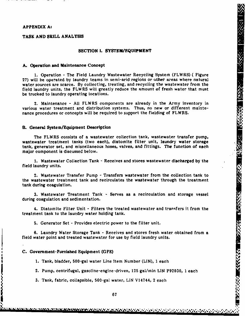
APPENDIX A:
TASK AND SKILL ANALYSIS
SECTION 1. SYSTEM/EQUIPMENT
A. Operation and Maintenance Concept
1. Operation - The Field Laundry Wastewater Recycling System (FLWRS) ( Figure27) will be operated by laundry teams in semi-arid regions or other areas where naturalwater sources are scarce. By collecting, treating, and recyclirg the wastewater from thefield laundry units, the FLWRS will greatly reduce the amount of fresh water that mustbe trucked to laundry operating locations.
2. Maintenance - All FLWRS components are already in the Army inventory invarious water treatment and distribution systems. Thus, no new or different mainte-nance procedures or concepts will be required to support the fielding of FLWRS.
B. General System/Equipment Description
The FLWRS consists of a wastewater collection tank, wastewater transfer pump,wastewater treatment tanks (two each), diatomite filter unit, laundry water storagetank, generator set, and miscellaneous hoses, valves, and fittings. The function of eachmajor component is discussed below.
1. Wastewater Collection Tank - Receives and stores wastewater discharged by thefield laundry units.
2. Wastewater Transfer Pump - Transfers wastewater from the collection tank tothe wastewater treatment tank and recirculates the wastewater through the treatmenttank during coagulation.
3. Wastewater Treatment Tank - Serves as a recirculation and storage vesselduring coagulation and sedimentation.
4. Diatomite Filter Unit - Filters the treated wastewater and transfers it from thetreatment tank to the laundry water holding tank.
5. Generator Set - Provides electric power to the filter unit.
6. Laundry Water Storage Tank - Receives and stores fresh water obtained from afield water point and treated wastewater for use by field laundry units.
C. Government-FurnIshed Equipment (GFE)
1. Tank, bladder, 500-gal water Line Item Number (LIN), 1 each
2. Pump, centrifugal, gasoline-engine-driven, 125 gal/min LIN P92030, 1 each
3. Tank, fabric, collapsible, 500-gal water, LIN V14744, 2 each
67
" *"' " "- *'." " " * '' " ' ' ,%
- ' % ",',= , ,.,,-,,-,s.,.-.-. ,,...,., ,, .,,. .. ,- ,' -, f,, .; ... ,. ...

ti
4. Filter assembly, diatomite, 420 gal/hr LIN, I each
5. Tank, fabric, collapsible, 1500-gal water, LIN V14881, 1 each
6. Hose assembly, 1-12 in., 11-1/2 National Pipe Standard Hose (NPSH), 10 ft, 7
each
7. Hose assembly, rubber water, braided, 1 in., 11-1/2 NPSH, 10 ft, 2 each
8. Hose, textile fiber, rubber-lined, 300 psi, J in., 11-1/2 NPFH, 25 ft, 1 each
9. Valve, plug, three-way selector, 1-1/2 ii., National Pipe Threads (NPT), 1 each
10. Valve, flow control, orifice type, 3/4 in., 14 NPT, 8 gal/min, I each
11. Nipple, pipe: brass, 1 in. diameter, 2 in. long, 1 each
12. Tee, pipe: brass, 1-1/2 in., 1 each
13. Nipple, pipe: brass, 1-1/2 in. diameter, 2-1/2 in. long, 2 each
14. Valve, gate: bronze, 1-1/2 in., 2 2ach
15. Adapter, straight, p;re to hose: 1-1/2 in., 11-1/2 NPT external, 1-1/2 in.1-1/2 NPSH, external, 2 each
16. Float, ball type: plastic, 8-in. diameter, 2 each
I;:
68
I 5 S ~ * . .b .1 -. . 1A ~ w.. -r r% ww . w, - . m q .

SECTION IL JOB TASK ANALYSIS SUMMARY
.00o0 S04 v
00
o> 0
****~ ~ ~ .0 = -!I,111 fai1I;I I0)0
E, -A EE
4v,
- IV
S0 r 0 V
'I0. '3. J2
W -a Cc3 p-
(664
.*. z* .* ...
bO - A

EU
CI E Ch:(A . c3: z
w C . ~. (A 0 S.o7CD 0 )4
zl z wq
00
0 mL. 4-'
S- 4- a- a
C 0 in E0 0
x 0 '4 .2 Z#
Z.~
E-4o
Cc M
0-0U2 0
z L) V) L. ,45 4 L
07
VI .V
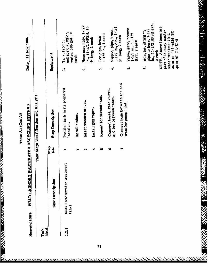
a~ 4
Cq o w
i E- [- ai - 5-SO 0 &.' i ~ s~Z ~ at
~~C4
0 0 4 )*'-cao 4)U, ~ ? ~~ £4 )V~JW
.1) ch E
0 4) 4
4)4 40)
p1 4 .
0 -wA44) )C?)
0-) 44) -P-
1. i 02 71
_ ~ 02 bO-e:

00- 4)*~ - I-.~ 0
A;
4- 0s a ; 0 -
z w 0g 4 1 .. C a. 4) - acc cm PC0. 411 ~ %- 4-
E as4 fl*: 0U) C1 c
0o Z
04- *41 .- 4 C
w C) 0 0.2
4k2 4 a a4- 0.-.00; 414V 0 U)
V). c2 0 4-o 0) 0
ad0 0
46
403
E04
724

cl.-
4~ . E
A =
-C
0 0
5 Z2
.~0 c-
> 0 0
as U
00 E
ClC
41-
73 44.

ej 0'
0 ~ ~ ~ i L. ~ ~ 3
> c 1 E 32 v a. I-z' :3 00 O.=UO0;fC~0. 0 eV V CL~-4 .~V
~' 3- 0 0 ~ 0 -- o
0%
4) o 0
-4 V W'oc 0 0c o
FA 0
o o .0 > .
* 0 0 z~ q-.4 ~0l CJ e> bo~ 06
V 1.- -a 0 ~U) s-
0 V- OV -W0
0 C 30 3Q0J
0f 00
z0 0 ~~
- ~ r C4 ( c4 -
C4
3:
-4
C 4
.4. z .2
* - .~i 04
5.160

2b 0
- -
~c S. E*~0 W
tko tw 0
,;.2
: OC, V
02 020
.~Q 3 0 4Vo000~I4 ~ 0 X- c
0i '
r -3~.
0 ' CL4. 0 u 40 W* 2 4
q* L n 4D - eq 9* l
e %
.4 0
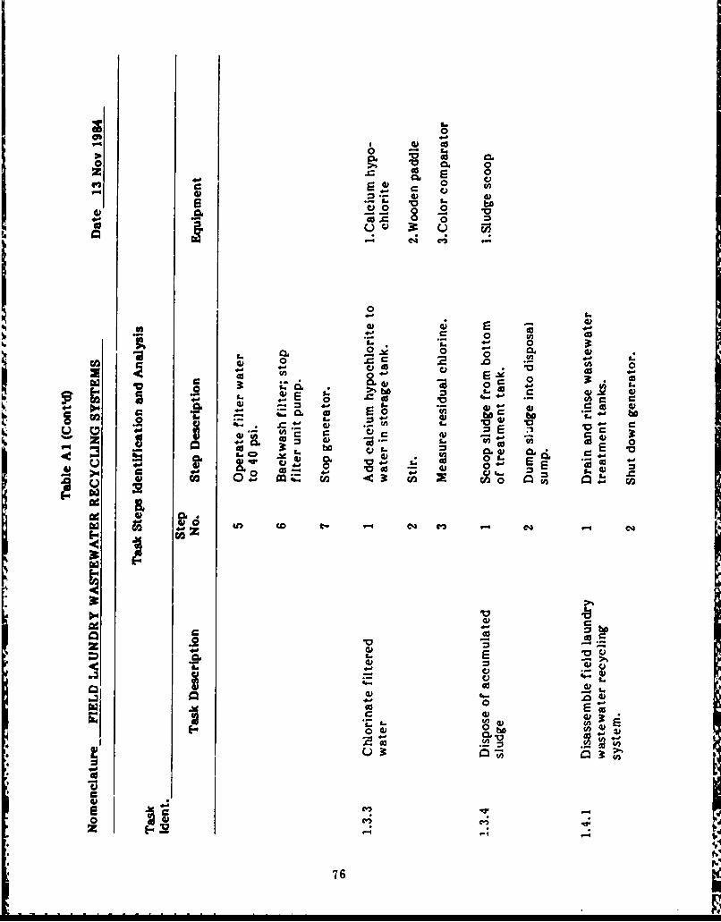
160
0 C
0 9)
41 ~ o0C C
0~- 2.O)
004L 0) m 0
V- 0 0)
W aa. a 0 - 0.4oL 41E 0 (fl
lotcl 4)0 I- 0cc 0a t o tw
0) - 4. CAL.
0 40o la 0X bO CO4 il v
o1 X 01 r0 in
8 ~~~ ~ ~ ~ C en ( - 4 4-eq .-&z
z 03
.2 20 0 E a 4#C
IV '
- 76

z
"4 0 0
%--
0 be4)
0 I
L. 0 . : U24) U) L. a
>I 0; r
-3 :"1 :0 ca .E
0- 0
po in 00, i
AD bD4 " C
I . a C4
33
N77

00
090 0 o 0 00 -
V I r I C.?
' a 04-
W- CJ
4) 0 0 a0 9 .
~40 c .. 2-
- 0
0,g16 S.s 0,0 .
C C&t, L0cib a 5b
00
-
0 a0oX. w
clCi~u
78

2.0 0 >
CL 4V c)
E 0
4 1 oC)
04C0 0 041)C)0 )cc 0
9. C A:gs I.
C) Cc
of) C1E ccS _ od xc
-- In E,- E- E-,J~f 4I.
bb
4) E
41 'o , w
cc 0 0
o) >1 404. )C C) t
0o -0 0 I4 0U
3: = '. -W ..
C . Z- 0,
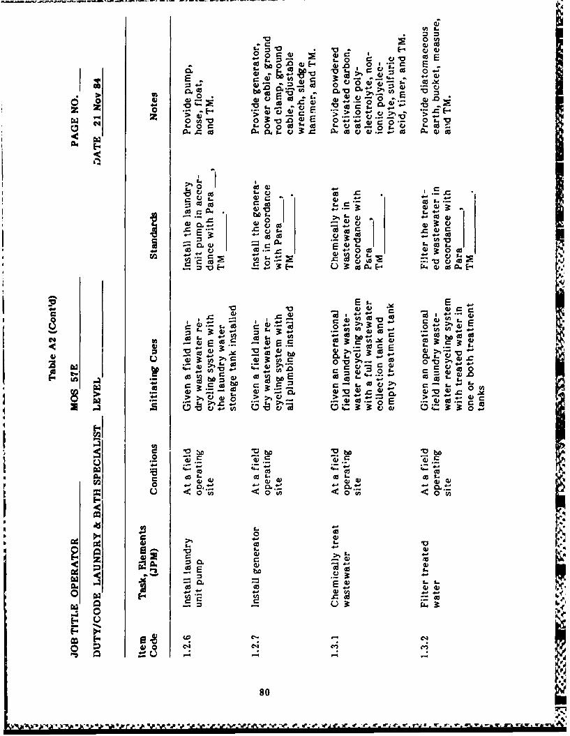
- L. = - 2 ,- -ro-
1"~ 0 1c 0EO- 0 ; 6 ., - ' 13 - E,
w~ ~ o ; V
-,; o., aj : V
0 0 w W2 L
z 2- W 0i >C ej-O .
0 c o4 o V-
a ca 0: .C *
* al
-O 4-00 0. 0 4 4 0V .
E r 0 u 0.- ~0 v0L.
cV +2': 0 L - as0 E -
0 f..~ 40 c- N o
14- L.- L. V
4. 4-0 00+
- - . P
1.. A 0- -)
4-4-
0o 0 0
0 W (
0Cdw q
p.~~~~~Z CLq. . . . .~A ei i '*y - -

so,0 .~V- 4-0 v
0n~It R 0 00 0~
E CLV O -
V od
4- Cco cc
.d bOco c
4-0W0 - 0
0) r c a.V~ I 0 (
4)~ .0 ve
0 v uv~a 0V E 0
.22
0 o0 o~
E~E
cI Vv0' 09
4) - % 0 .
p.~0 bO4-4
CV 4)- 4)04
81

PERSONNEL PLANNING DATA
Task frequencies listed herein are predicted values of task occurrence pc, missionbased on an assumed mission length of 10 days and an operating schedule of 20 hours perday (one operator per shift, three shifts per day).
Total man-minutes identified in the task schedule includc productive time per taskonly; nonproductive time (i.e.)time spent waiting for mixing, sedimentation, etc.) is notIncluded.
, 1d
d
82
.5- ~ ~ .*.. ~ ~ ,s* r~ , * *s*.~ ~ .' ~ ~ . .. ' ,.~. ~. **,

96.
Saw* I3_ _ _ __ _ _ _ _ _
zo~
f 14
83 ell

CD 0 C 0 CD C C
E- - - - - -~ - -' - -
cc
.3.
z
w w wt- ____ _e-__2___ ___ ___ ___ ___
A IM
z ____________rot_____
zi c I r
A.84
6 _ _ _ _ _ _ __ _ _ _ _ _ _ _

19
IzI0.I_ _ __ __ _
-
I FFogrh3
II _ _ _
Il -_ _ _
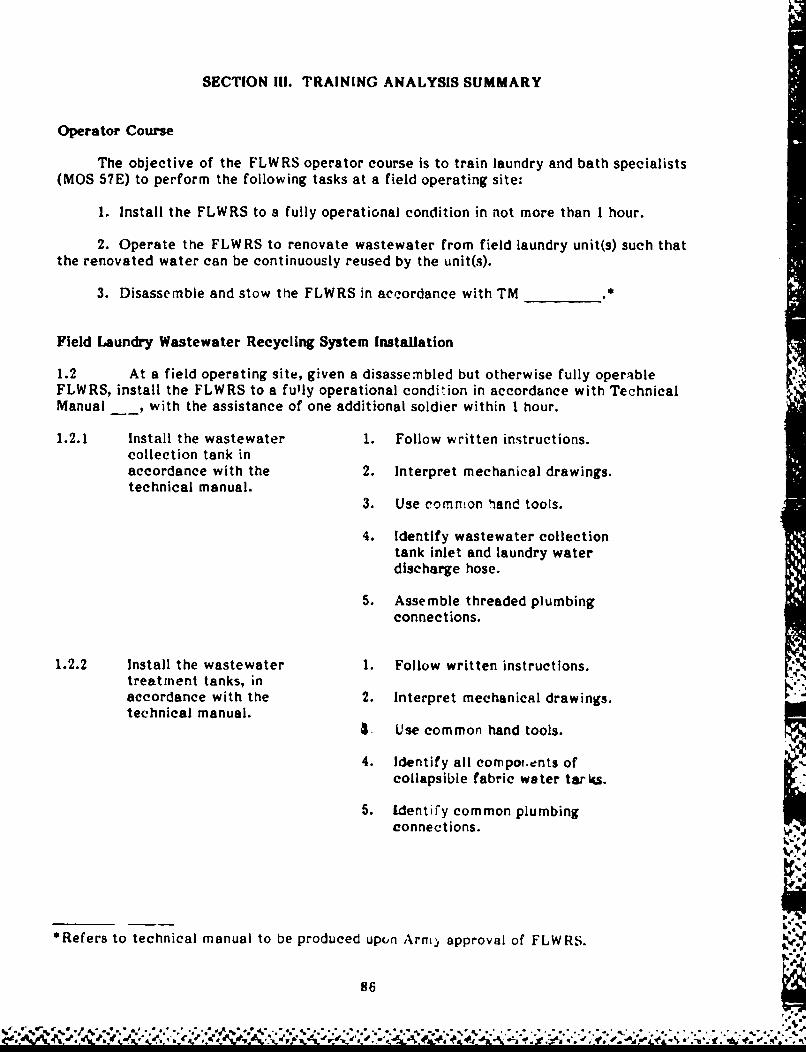
SECTION III. TRAINING ANALYSIS SUMMARY
Operator Course
The objective of the FLWRS operator course is to train laundry and bath specialists(MOS 57E) to perform the following tasks at a field operating site:
1. Install the FLWRS to a fully operational condition in not more than 1 hour.
2. Operate the FLWRS to renovate wastewater from field laundry unit(s) such thatthe renovated water can be continuously reused by the unit(s).
3. Disassemble and stow the FLWRS in accordance with TM *
Field Laundry Wastewater Recycling System Installation
1.2 At a field operating site, given a disassembled but otherwise fully operableFLWRS, install the FLWRS to a fully operational condition in accordance with TechnicalManual _, with the assistance of one additional soldier within 1 hour.
1.2.1 Install the wastewater 1. Follow written instructions.collection tank inaccordance with the 2. Interpret mechanical drawings.technical manual.
3. Use common liand tools.
4. Identify wastewater collectiontank inlet and laundry waterdischarge hose.
5. Assemble threaded plumbingconnections.
1.2.2 Install the wastewater 1. Follow written instructions.treatment tanks, inaccordance with the 2. Interpret mechanical drawings.technical manual.
. Use common hand tools.
4. Identify all compo.ents ofcollapsible fabric water tar 4s.
5. Identify common plumbingconnections.
*Refers to technical manual to be produced upon Arm) approval of FLWRS.
86
.- V . d@

1.2.3 Install the filter unit 1. Follow written instructions.in accordance with thetechnical manual. 2. Interpret mechanical drawings.
3. Use common hand tools.
4. Identify all components of thefilter unit.
5. Identify common plumbing items.
6. Assemble threaded plumbingconnections.
1.2.4 Install the laundry water 1. Follow written instructions.holding tank, in accordancewith the technical manual. 2. Interpret mechanical drawings.
3. Use common hand tools.
4. Identify all components ofcollapsible fabric water tanks.
5. Assemble threaded plumbingconnections.
Field Laundry Wastewater Recycling System Operation
1.3 At a field operating site, given a fully assembled and operational FLWRS,operate the FLWRS in accordance with Chapter _ of the technical manual to renovatewastewater from field laundry unit(s) such that the renovated water can be continuouslyreused by the field laundry unit(s).
I
1.3.1 Chemically treat the 1. Follow written instructions.wastewater in accordancewith the technical manual. 2. Measure pH of water samples.
3. Measure liquid and dry chemicals.
4. Adjust the pH of water to desiredlevels.
5. Operate gas-engine-driven pumps.
6. Operate three-way and gate valves.
, 7. Operate mechanical, electric, orelectronic timers.
87
4t L. .e %% %

1.3.2 Filter the treated water 1. Follow written instructions.in accordance with thetechnical manual. 2. Operate gas-engine-driven generator
sets.
3. Operate mechanical, electric, orelectronic timers.
1.3.3 Chlorinate the filtered 1. Follow written instructions.water In accordance withthe technical manual. 2. Measure pH of water samples.
3. Measure dry chemicals.
4. Calculate quantity of calciumhypochlorite required.
5. Measure residual chlorineconcentration of water samples.
Preparation for Movement
1.4 At a field operating site, given an assembled FLWRS, disassemble and stow theFLWRS in accordance with Para , Tectinlcal Manual
1.4.1 Disassemble the FLWRS 1. Follow written instructions.in accordance with thetechnical manual. 2. Interpret mechanical drawings.
3. Use common hand tools.
4. Identify all components ofthe FLWRS.
1.4.2 Stow the FLWRS in 1. Follow written instructions.acco-dance with thetechnical manual. 2. Interpret mechanical drawings.
3. Identify all components ofthe FLWRS.
88
iI

SECTION IV. I ANPOWER SUMMARY
A. Installation
The FLWRS can be Installed in 1 hour by two persons (one MOS 57E10 with onehelper, and one MOS nonspecific).
B. Operation
All operator tasks for the FLWRS can be performed by one operator (MOS 57E10).An operating crew of three (MOS 57E10) would be required for a 20-hour-per-dayoperating schedule. The FLWRS operators would be supervised by the laundry teamsupervisor.
C. Maintenance
All FLWRS components are currently in the Army inventory within various othersystems. Maintenance requirements for these components are already established andtherefore were not included in this report.
89
.", .. ' .," . '."''.'"".- ", - " "." , • , . -, ., . - - ..- ,. . . ... . . . .. .

APPENDIX B:
EXCERPT FROM TABLE OF ORGANIZATION AND EQUIPMENTFIELD SERVICE COMPANY, GENERAL SUPPORT, FORWARDTOE 29114H400 CHANGE 17 (CURRENT AS OF APRIL 1984)
Lc
In
I-.
C. n
0 0)
09
"tv~~C -% A-

z
w cc4
OCL = u. ft ft C% (A - 9 4
z ft
0.a.a.a
0 -
v 9 90C- M__ _fn__ _ _CIS _ _
M f -
ed a a
ic cc ~ wdc 0.. 0 . 000
W i
100
4A.-
Qt --
tiI Lfii4c La
0.d. ,~ 91
"I" p C

I'
Laaca ow
LAJO _ _ _ _ _ _
km
U.'U
w KL~~i~ cc C-0V- N 0 0 0
- Nea-) a .
(AccZ 2uii L
L
NA N s N
CL,
u' u1 tn cc
4.00) -7
4W40L. -I .
NLJ N A __ Q ( .
40 =0 054 4
(.DO 0 __ ____ __ 92
S~~~ 4 188'%
M L . __ _ _ _ _ _ __ _ _ _ _ _ _ __ _ _ _ _ _ _ __ _ _ _ _ _ _ __ _ _ _ _ _

APPENDIX C:
PROGRAM OF INSTRUCTION FOR OPERATION AND OPERATORMAINTENANCE OF FIELD LAUNDRY WASTEWATER RECYCLINGSYSTEM
SECTION 1. PREFACE
A. Course: Operation and Operator Maintenance of Field Laundry WastewaterRecycling System (FLWRS) - Proposed
B. Purpose: To provide enlisted personnel with the knowledge and skillsrequired to deploy and operate the FLWRS, and to performoperator maintenance
C. Prerequisite: Assignment as instructor or operator of a field laundry unit
D. Length: Peacetime - 5 days
E. TrainingLocation: To be determined
* F. MOS FeederPattern: Prerequisite MOS MOS trained In this course
Operator 57E Same as prerequisite
G. AmmunitionRequirement: No ammunition required
SECTION I. SUMMARY
Course: Operation and Operator Maintenance of Field Laundry Wastewater
Recycling System (FLWRS) - Proposed
'4 Hours: 40
Hours Annex*
A. AcademicSubjects: Operation and operator maintenance 40 A
B. NonacademicSubjects: Not applicable
*See Section IV, p 94.
93
1Wa~ ~iw q, ~ ~ .~I
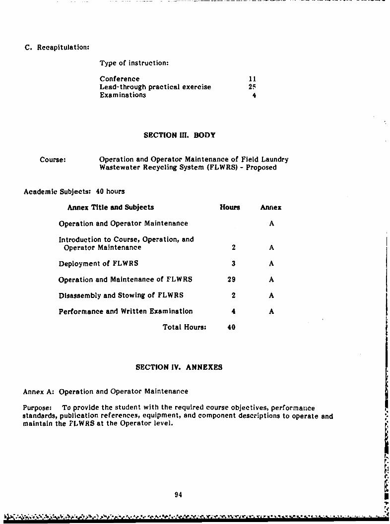
C. Recapitulation:
Type of instruction:
Conference 11Lead-through practical exercise 2,5Examinations 4
SECTION I. BODY
Course: Operation and Operator Maintenance of Field LaundryWastewater Recycling System (FLWRS) - Proposed
Academic Subjects: 40 hours
Annex Title and Subjects Hours Annex
Operation and Operator Maintenance A
Introduction to Course, Operation, andOperator Maintenance 2 A
Deployment of FLWRS 3 A
Operation and Maintenance of FLWRS 29 A
Disassembly and Stowing of FLWRS 2 A
Performance and Written Examination 4 A
Total Hours: 40
SECTION IV. ANNEXES
Annex A: Operation and Operator Maintenance
Purpose: To provide the student with the required course objectives, performanicestandards, publication references, equipment, and component descriptions to operate andmaintain the FLWRS at the Operator level.
94

File No. Classifleation Type of Instruation
FLWRS-A-010-010 - Introduction to Operation and Operator Maintenance
Hours: 2 U* 2C**
Objective: In a training environment, given course material, referenced technicalmanual, and the FLWRS, the student will:
(a) Identify referencpd publications and state their applications in thislesson
(b) State the purpose, capabilities, features, and technical principles ofoperation
(c) Identify the components and their function and location in the system
(d) Relate the components of the FLWRS to the technical manualreference.
Completion of tasks will be verified by an instructor as specified intechnical manual reference.
References: Technical manual on FLWRS.
*Uncl&ssified.
**2 Classroom hours.
File No. Classification Type of nstruction
FLWRS-A-010-020 - Deployment of FLWRS IC, 2 1,TPE*
Objective: At a field operating site, given a disassembled but otherwisefully operable FLWRS, the necessary toots and materials, technicalmanual, and a student workbook, the student will:
(a) Assemble the FLWRS
(b) Identify the components of the system
(c) Identify key features of each component
(d) Perform preventive maintenance checks and services on the FLWRS.
References: Technical manualStudent workbook.
*Lead Through Practical Exercise.
.%. 995=
AIINA'0.1~* ..k.'ll

File No. Classification Type of Instruction
FLWRS-A-010-030 - Operation and Maintenance of the FLWRS
Hours: 29 U 8C, 21 LTPE
Objective: At a field operating site, given a fully assembled andoperational FLWRS and technical manual, the student will:
(a) Perform preventive maintenance checks and services on the FLWRS
(b) Operate the FLWRS
(e) Perform water sampling and testing procedures
(d) Perform troubleshooting on the FLW RS
(e) Perform the FLWRS diagnostic program
(f) Perform operator maintenance on the FLWRS.
Performance and completion of tasks will be verified by an instructor.
References: Technical manualStudent workbook.
File No. Classification Type of Instruction
FLWRS-A-010-040 - Disassembly and Stowing of FLWRS
Hours: 2 U 2 LTPE
Objective: At a fie d training site, given an assembled FLWRS, thestudent will:
(a) Disassemble and prepare the FLWRS for movement to
another operating location
(b) Prepare the FLWRS for storage.
Performance and completion of tasks will be verified by aninstructor as specified in the technical manual.
References: Technical manualStudent workbook.
96
EWE Team Distribution
Chief of Engineers US Army Engineer Division gollinI API. DC 20330
ATT.- Ai -ZCF-B Huntsville 35807 AF/LEEEU
ATTN: DAE1dZCF-U ATTN: Chief. IMDED-CS
ATTN: DAE-ECZ-A ATi: Chief. MiNDED-ME Little Rock APB
AIIMl Chief, MNITdD-l9 ATTN% 3.4/8eet
US Army Engineer District Lover Mississippi Valley 3910
go. York 10007 ATII Chief. D Potrick API, FL 32925
ATTU: Chief. NANE- Ohio liver 45201 ATTN ]XQ
ATTM: Chief. Deii Sr. ATTN: Chief. Ber Div
Pittsburgh 15222 North Centrel 6005 Tinker AP. 0[ 73145
ATTNI: Chief. Engr Div AITI Chief. Fngr Planning B 28654 ABC/DIEC
Philadelphia 19106 Missouri liver 68101
ATTN: Chief. APE)-E ATTN: Chief. PMDErI-T Tyndall AP FL 32403
Norfolk 23510 Souchvestern 75242 AirSC/PT
ATTI: Chief,. WAOl-D ATTN: Chief. SMDED-THuntington 25721 North Pacific 97208 Slde Research Advisory Board 20418
ATTN: Chief, OI4ED-H ATTI Chief, Engr Div.
Wilmington 286401 South Pacific %I11 Dept of Trnseporttion
ATTN: Chief, SAWEl-PM AIM'" Chief, IPD-TC ToLaeoee, FL 32304
ATTW: Cief. SAMeM-E ATTN: LaboratOrYCharlestOn 29402 Pacific Ocean 96851 Dept of transportation Libcery 20590
ATI: Chief, Engr Div AInM: Chief. Engr DivSavannah 31402 ATTI: Chief, PoDED-NP Trameportation lesearch board 20410
ATM: Chief. SASAS*L ATTII Chi@., PODED-FJacksonville 32232 Airpors and Contruction Services Dir
ATTN: Env lee Sr 5th US Army 70234 Ottara. Ontario, Canada hA 0MB
Mobile 36628 ATTMI AYI-LG-E Division of Building Research
ATTN: Chief, SAMEW-C otve, o , Cnad a Koeeer 6Vicksburg 39180 6th US Army 94129 Ottawa, Ontario, Canada KIA 086
ATTN: Chief. Engr Div A"I: APKC-ENLouilVLe 40201 MatOal Defense Ceadquarters
ATTN: Chief. Engr Div 7th US Army 09407 Ottawa, Ontario, Canada IlA 012
St. Paul Si01 ATTNI AErlM-HD-eD 105ATTN: Chief. ED-H O1/86
Chicago 60604 10th Medical Laboratory
ATTI Chief. mCCCO-l APO MEW YORK 09180ATTM: Chief. XCCED-"ATTI: Cief, NCCPD-EI US Army Foreign Science 0 Tech Camter
A7IM: Chief, NCCPEPES AIT: Charlottesville, VA 22901
St. Louis 63101 ATlM Far teat Office 96328
ATTII Chief. ED-SAIIM: Chief. ED-D USA AIBADOOM
Kansas City 6106 ATrN MDAo-LCA-OC 07801
ATTII Chief, Cngr DivOjmaha 6102 weat Point. ml 10996
AIIM: Chief, Engr Div ATTN: Dept of Mechanics
Little lock 72203 ATTM: Library
ATTI: Chief. Enir DivTulsa 74102 Ft. Salvoir, VA 22060
AII: Chief. Engr Div ATTI: Learning Resourcee Center
Fort Worth 70102 AII ATSE-TD-TL (2)AIIM: Chief. SWFED-D
ATTS: Chief. SWFED-MA/MI Ft. Clayton Canal Zone 34004
Cveston 77550 AIIM: DFAE
ATTN: Chief. SWCAI*LAITI Chief, SWGCO-M Ft. A. P. ill 24502
Lot A"*le$ 90053 ATTIi FEATTM: Chief. SILED-E
Son FranciscO 94105 Ft. Laavenvorth. 95 66027
ArrN: Chief. Engr Div AIIM ATZLCA-SASacramentQ 95814AIN: Chief. SPKED-D Ft. Lae, VA 23801
Far feast 96301 ATiIM DWC-D (2)
ATiM: Chief. Engr DivSeattle 98126 Ft. McPherson, CA 303)0
A:TN: Chief, Ma'SEd-FN AIIM: AFEI-COAITM: Chief. EN-DO-SEArlI: Chief, MPSEU-PL.WC Ft. Monroe, VA 2)051AIIM: Chief, NPSEM-PL-EI AIMt ATEl"AD (3)
Wall& Walla 99362 ATIN ATEN-FE-E
ATIM: Chief, Engr Div AIt: ATO-FEU
Alaska 99501 Aberdeen Proving Ground. MD 21005
ATTM: Chief, MFASA- ATrI AMCNE
5, AIIM: mSE-EWUS Army Engineer Division ATIrM: OAC-AA1-Eme. England 02156ATTN Chief, ADEN-T Naval Faclities Engr Comnd 22)32
North Atlenti 10007 AITI: Code 00
AIIM: Chief, MADE -Td Middle East (lear) 22601 US Navel Oceanographic Office 39522
ATTM: Chief, MeDED-T AIIM: Library
South Atlantic 30303ATTM: Chief, lADEN-It Naval Training equipment Center 32813
iAIIN: Technical Library
J- ,.'%,:-::Y;:,"- . ::--I .d .-. - . ._, - . :".' - - ','-,' : " ",•. ", .

File No. Classification Type of Instruction
FLWRS-A-010-050 - Performance and Written Examinations
Hours: 4 U 4 El
Objective: In a training environment, given a fully assembled andoperational FLWRS, the student will:
(a) Identify key features of the technical manual andtheir application
(b) Demonstrate knowledge of the purpose, capabilities, andfeatures of the FLWRS
(c) Demonstrate knowledge of technical principles ofoperation
(d) Identify components and their location on the FLWRS.and in the manual
(e) Perform preventive maintenance checks and servicestasks and procedures
(f) Conduct one complete treatment cycle using the FLWRS
The student will demonstrate knowledge and perform the abovetasks without error in accordance with the technical manual. Thestudent's performance will be evaluated by an instructor usingreferences listed below.
References: Technical manualWritten instructions.
97
-. S.
4g,.

USA-CERL DISTRIBUTION
Chief of Engineer* KOKIUS Combined forces Com4nd 95301ATTN: DAENI-NS-L (2) ATMT¥ CUSA-HHC-CFC/Ergr
ATTN: OAEN-CCPATTN: OA-CW INSCO -- Ch. Iner. DivATTN: DAEN-CME AT: Fecilities Engineer (3)ATT: DAIN-CWXI-RAT'TN: DAEN-CWO NOw, ATT: DEM (3)
AITN: DAEN-CWPATTN: DAEN-EC "qhCATTN: DAEM-ECC AlTIRi 'TNC-SA 20315ATT: DAEM-ECE ATTri Facilitie Engineer (3)ATTN: DAIN-ECRATT* DAEN-RD NALADCOH, ATTN: ORDYA-F 01760
ATTN: DAEN-RATTM: DAIM-RON TASCOm, FPa. Div. 40090A TflId,: DAIM¥olUA1"": DAEIN-ZC TILAOCATM"N: DA9¥*ZCE HQ, TLADOC. ATTW: ATEM-DENAlTN: DAEV-ZCF ATTN: DEN (19)ATTMi DAEI-ZCIAIM: DAIZCM TSACON, ATTN: STSAS-F 63120
ATTN: OAIN-ZCZ
feSA. AiN: Library 22060 USACC, ATTN: Facilities engr (2)
AITM: DET 11 79;06 WISTCo~qA'IiM: DIN. Ft. Shelter 96856
US Amy Engineer Districts ATTN: APEN. . t 9
ATTN: Library (41) AM: APEN-t4
US Amy Engineer 0~vteions SHAPE 09055ATrmy Librery (D ) ATTN: Surv. Section. MCC-OPS
Infrestructure Branch. LAJIDA
US Army Europe HQ USEUCON 09128AEAED-OOCS/EnSr 09403 AMs ICJ /
7-WE
[SAl 090A1v Corp.AiiM: DI () FORT BLVOIR. VA 22060 (7)
VtI CorpD ATTM: Canadian Liaison OfficeAW"IT Corp AT : Water Resourcee Support CtrA2Mi DIN (i) ATTM: Engr Studies Center
212t Support Comand ATTN: Engr Topographic Lab.ATS 01EN (12) ATI ; ATZA-DTe-SU
USA Berlin ATTN: ATZA-OTI-ENASM DIM (!I) ATTII: &D Comand
USASIAPATM: DEN (10)
Allied Comnd Ijrope (ACE) CUlL. AIM Library 03755AT~iM DIM (3) SWES ATN: Library 39180
$th USA, Korea (19) HQ. XVIII Airborn Corp#
USA Japan (USAJJ) and Fort Bragg
ATTM: AJEN-DE 96343 AIr: AFZA-FE-eI 26307ATTM: DEH-Honshu 96)43ATTh: OEH-Okinava 96311 Aree Engineer. AEDC*Area Office
Arnold Air Force Station, TN 37389
416(h engineer Comaind 60623
AM : FaciLities engineer Chanute AFB. IL 618683345 CEBlDI. Stop 27
US Military Acedemy 10966
ATTN; F&Cl1itiel Engineer Norton AfS. CA 92409
ATIM: DOpt of oogrophy 6 ATM? AFBCe-KX/DCEComputer Science
ATTMi DSCPER/IAEO-A AfIESC. Tyndall AtB. FL 32.-o
A#,qRC, ATTN OR.X)4-WE 02172 NAVFAC
Arl Engineering Coomand (7)
USA A.ICON 61299 ATr¥: Division Offices (6)
AtTr: DRCIS-R[-I ATrill Naval Public Works Center (9)ATTN: DISA-IS AIMI Naval Civil nr Lab. (3)
AMqC - Dir.. Inst.. 6 Seruc AMI" Library, Code LOBA NCIL 93043ATTN: DeN (21) Defense Technical Info. Center 22314
DLA AI-T: DLAWI 22314 ATTN: DA (2)
DNA ATTN: NAD! 20305 Engr Societies Library, MY 10017
FOACON Nati Cuard 8,reau Inttl. Div 20310
FOISCON Engr, AIIN? AFIMDDIHATiSN DIn (23) US Covt Frint Office 22304C OReceiving Sect'Depis,tory Copies (2)
AiTN: H4SLO-F 76234 US Army Env. Hygiene Agency
ATTN: Facilities Engineer AII H4HB1 2;010Fitzsimons ARC 80240Walter Reed AMC 20012 National Bureau of Standards 20899
321
01 86
~is.,.. ... *,"**.. .. ,..'o." .. . ,*.'". . .% .. . .

,'.,ilk