development and implementation of a segment/junction … · development and implementation of a...
TRANSCRIPT

FHWA-NJ-2012-001
Development and Implementation of a Segment/Junction Box Level
Database for the ITS Fiber Optic Conduit Network
FINAL REPORT October 2011
Submitted by
Dr. Michael Shenoda, Assistant Prof. Civil Engineering Department
The College of New Jersey
Dr. Fadi Karaa, Assoc. Prof. Civil & Environmental Engineering Department
New Jersey Institute of Technology
NJDOT Research Project Manager Edward Stephen Kondrath
In cooperation with
New Jersey Department of Transportation
Bureau of Research and
U.S. Department of Transportation Federal Highway Administration

DISCLAIMER STATEMENT
The contents of this report reflect the views of the author(s) who is (are) responsible for the facts and the accuracy of the data presented herein. The contents do not necessarily reflect the official views or polices of the New Jersey Department of Transportation or the Federal Highway Administration. This report does not constitute a standard, specification, or regulation.

TECHNICAL REPORT STANDARD TITLE PAGE
1. Report No. 2.Government Accession No. 3. Recipient’s Catalog No.
FHWA-NJ-2012-001
4. Title and Subtitle 5. Report Date
Development and Implementation of a Segment/Junction Box Level Database for the ITS Fiber Optic Conduit Network
March 2012
6. Performing Organization Code
TCNJ/NJIT 7. Author(s) 8. Performing Organization Report No.
Michael Shenoda, Fadi Karaa
9. Performing Organization Name and Address 10. Work Unit No.
The College of New Jersey PO Box 7718 Ewing, NJ 08628-0718
11. Contract or Grant No.
12. Sponsoring Agency Name and Address 13. Type of Report and Period Covered
New Jersey Department of Transportation U.S. Department of Transportation PO 600 Federal Highway Administration Trenton, NJ 08625 Washington, DC 20590
Final Report (June 2011 to Oct. 2011)
14. Sponsoring Agency Code
15. Supplementary Notes
16. Abstract
This project initiated the development of a computerized database of ITS facilities, including conduits, junction boxes, cameras, connections, etc. The current system consists of a database of conduit sections of various lengths. Over the length of a section materials sometimes change and the numbers, types, and locations of junction boxes are unknown. The accurate location of conduits in the medium and long-term can be best undertaken with a cross-referenced segment and junction box inventory. This work focused on fiber optic conduit and junction boxes and the development of a detailed database of segment-level conduits. It involved locating, surveying, and inspecting various conduits and junction boxes to allow the identification of physical characteristics (diameter, length, material, etc.) and location characteristics (GPS coordinates, soil type, under asphalt/concrete/grass, proximity to other utilities/clutter, etc.). This field verification will improve the quality and accuracy of inventory information for future construction and expansion of the network. The existing inventory database(s) of the ITS fiber optic conduit system, which are at the section level and do not include junction box data, was used as a starting point for the development of an expanded and improved system. A joint TCNJ and NJIT team worked to develop the system.
17. Key Words 18. Distribution Statement
Underground conduit, Junction box, Fiber optic conduit, Segment, Inventory database
19. Security Classif (of this report) 20. Security Classif. (of this page) 21. No of Pages 22. Price
Unclassified Unclassified
27
Form DOT F 1700.7 (8-69)

ACKNOWLEDGEMENTS
The authors wish to thank the New Jersey Department of Transportation for their assistance and support, particularly Camille Crichton-Sumners, Manager of Research, Edward S. Kondrath, Project Manager, and Mark Renner of NJDOT ITS South Operations. The authors also wish to thank contributing NJIT student Sugata Banerji and TCNJ students Daniel Guadron, Daniel Levine, Paul Napoli, Joseph Serrao, Stephen Shiffer, Paul Triantafyllou, Juan Urena, and Christian Zografos for their support in this research, and TCNJ professor Allen Katz for his assistance and advice.

TABLE OF CONTENTS
Page
1. Background . . . . . . . . . . . . . . . . . . . . . . . . . . . . . . . . . . . . . . . . . . . . . . . . . 1
2. Project Objectives . . . . . . . . . . . . . . . . . . . . . . . . . . . . . . . . . . . . . . . . . . . . 1
3. The State of Database Development for NJDOT ITS Facilities . . . . . . . . . 2
4. ITS Facilities Inventory Design . . . . . . . . . . . . . . . . . . . . . . . . . . . . . . . . . 3
5. ITS Facilities Inventory Development Plan and Data Structures . . . . . . 4
6. ITS Facilities Inventory System Architecture and Functionality . . . . . . 8
7. ITS Junction Box Data Acquisition Plan, Training and Field Investigations . . . . . . . . . . . . . . . . . . . . . . . . . . . . . . . . . . . . . . . . . . . . . . 18
8. Conclusions and Recommendations . . . . . . . . . . . . . . . . . . . . . . . . . . . . 20
LIST OF TABLES
Page
Table 1 - Junction Box Data Structure 6
Table 2 - Segment Data Structure 7

LIST OF FIGURES Page
Figure 1. Entity – Relationship Diagram 4
Figure 2. System Architecture Diagram 8
Figure 3. Login Page 9
Figure 4. Homepage 10
Figure 5. Manage Sections Page 10
Figure 6. View Sections Page 11
Figure 7. Section Detail Page 11
Figure 8. Manage Segments Page 12
Figure 9. View Segments Page 12
Figure 10. Segment Detail Page 13
Figure 11. Manage Nodes Page 13
Figure 12. Manage Junction Boxes Page 14
Figure 13. View Junction Boxes Page 14
Figure 14. Junction Box Detail Page 15
Figure 15. Add New Junction Box Page 15
Figure 16. Completed Add New Junction Box Page 16
Figure 17. Manage Extremities Page 16
Figure 18. Manage Users Page 17
Figure 19. Add User Page 17
Figure 20. Edit User Account Page 18

1. BACKGROUND The New Jersey Department of Transportation (NJDOT) operates and maintains a network of thousands of miles of conduits (Intelligent Transportation Systems (ITS) infrastructure); approximately 600 miles of it carries fiber optic cables that are vital to the State of New Jersey communication system. These conduits have to be located and marked prior to construction activities to avoid potential damages. Currently, NJDOT locates conduits using trace wires (TW) and radio frequency (RF) detection methods. However, a portion of the network has missing or damaged trace wires, which pose a significant problem. A recent project by the Team of TCNJ and NJIT, sponsored by NJDOT with partial support from UTRC, evaluated various detection techniques, and focused on four alternative detection techniques: acoustic transmission (AT), ground penetrating radar (GPR), ground penetrating sonar (GPSon), and the measurement of electro-magnetic impedance (EMI), as well as on extensions and improvements to the TW and electro-magnetic induction method.
As part of the findings and recommendations of that study, the development of a computerized database of junction boxes was considered as an essential component of a long-term solution to the detection problem, as the inventory of the ITS consists of sections of conduits of variable lengths, diameters and materials, and often crossing several junction boxes, which are not inventoried.
2. PROJECT OBJECTIVES The overall objective of this project is to start the development of a computerized database of all ITS Facilities, including conduits, junction boxes, cameras, connections, etc., with an initial focus on the junction box facilities currently missing from the current inventory system. The current system consists of a computerized table of conduit sections, with various lengths, sometimes changing materials and unknown intermediate numbers, types, and locations of junction boxes. It is clear that the accurate location of conduits in the medium and long-term can be best undertaken with a cross-referenced segment and junction box inventory.
The key thrust of the proposed work is to focus on pipes and junction boxes through the development of a detailed dynamically updated inventory of all segment-level conduits (junction box to junction box) and the junction boxes themselves. This database is a high priority pre-requisite for the implementation of a rational fiber optic (and other) cable location program, and as a core inventory system for all construction and asset management activities in the network. In the process of continuing to locate, survey and sometimes inspect various conduits and junction boxes, the availability of this information would allow the identification for every facility of its location fields such as

physical characteristics (diameter, length, material, depth of cover (starting, ending), etc.), its location characteristics (soil type/suitability for GPR, under asphalt/concrete/grass, contiguity to other utilities/clutter, etc.), as well as its history and frequency of inspection, thus improving the quality and accuracy of inventory information for future construction and expansion of the network.
The existing inventory database(s) of the fiber optic conduit system which are at the section level and do not include junction box data, will be used as a starting point for the development of an expanded and improved system.
This project aims at developing the information structure required to enable the coverage of all facilities managed by ITS, and the development of a pilot system where a significant amount of junction box (JB) data can be uploaded. In order to preserve data integrity, the original section-level data is integrated in the system, in order to enable the gradual transition of the system towards a comprehensive inventory database management system of all ITS facilities. In addition to the system design and development work, the surveying of various junction boxes was also undertaken by this Team.
Key criteria for success of this study include:
1- TECHNOLOGY SELECTION: the ability to develop a system that can be accessed by multiple users, and maintained by ITS and other NJDOT departments.
2- CONSERVATION AND IMPROVEMENT OF INVENTORY KNOWLEDGE: the ability to create a new set of data related to junction boxes without losing the prior information related to section-level data. Also the junction box data can help improve gradually the conduit information, as segment-level (JB to JB) data can improve the accuracy of conduit information.
3- NETWORK INVENTORY CONNECTIVITY AND COMPLETENESS: the ability to improve the information base regarding the location and completeness of the entire network and its facilities, both as a concerted database effort, and as a result of future field investigations. For example, the inventory of all pipe extremities within each junction box and their association with segments and sections, allows to us define a real network model.
3. THE STATE OF DATABASE DEVELOPMENT FOR NJDOT ITS FACILITIES At the outset, the inventory of ITS facilities consists of section level data for conduits, often extending several miles and crossing several junction boxes. This creates several possible inaccuracies (diameter, material, trace wire missing or in place), as well as

incomplete records (missing sections from a milepost value to another along a highway or roadway managed by NJDOT, missing secondary sections and nodes in the network).
In order to achieve the objectives stated above, a new database design, that emphasizes completeness and connectivity, was devised and implemented for a large sample of junction box data collected during field investigations.
4. ITS FACILITIES INVENTORY DESIGN The new ITS Facilities inventory makes it possible to manage the system as a network of nodes and links, with all specifications for various nodes and links.
As mentioned above, the current system inventory is characterized by the following:
• It consists of Fiber Optic conduits divided by sections along or across major roadways with Milepost (MP) Start and MP Finish.
• Sections may contain tens of junction boxes, with changes in materials and depths, which explain the “Unknown” value for material, depth and diameter fields in many records, as well as missing sections for some milepost ranges.
• Nodes such as junction boxes, cameras and other facilities are not inventoried.
In order to implement a network-based inventory system, the creation of nodes, with junction boxes being the default and key node type, is at the center of the new design.
The system design consists of the following entities and relationships, which are displayed in Diagram 1:
1- Current sections remain the highest level entity in conduit description, and the existing data is ported to that entity.
2- A new entity (node) is added, with type values of junction box (JB), camera, controller, etc.
3- A new entity (segment) is created, which represents a node to node conduit pipe containing one or more fiber optic cable stretches.
4- A section therefore “contains” or is connected to many nodes (mostly JB), and thus a hierarchical relationship exists between sections and its related “children” nodes.
5- A section also has many children segments (node to node), and a hierarchy of section to segment also exists (1:n) relationship.
6- A node contains multiple extremities of segments of pipes (1: n relationship), which can be characterized once a junction box has been inventoried, and its interior section surveyed.
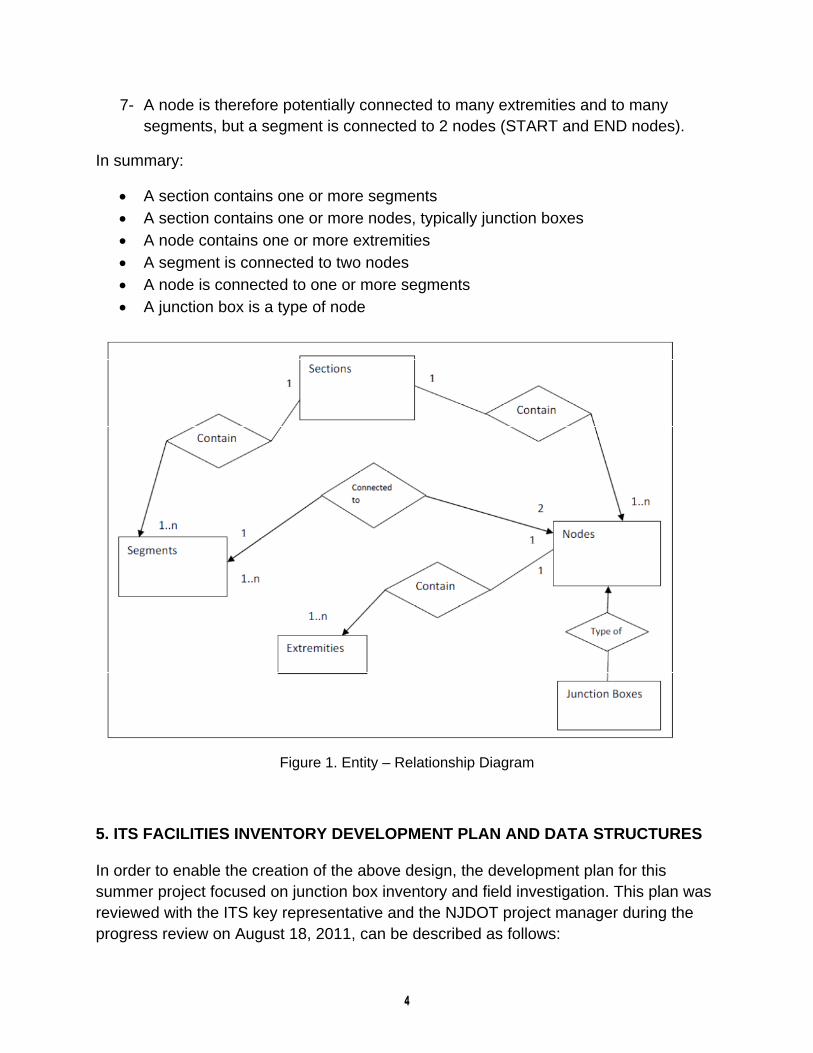
7- A node is therefore potentially connected to many extremities and to many segments, but a segment is connected to 2 nodes (START and END nodes).
In summary:
A section contains one or more segments A section contains one or more nodes, typically junction boxes A node contains one or more extremities A segment is connected to two nodes A node is connected to one or more segments A junction box is a type of node
Figure 1. Entity – Relationship Diagram
5. ITS FACILITIES INVENTORY DEVELOPMENT PLAN AND DATA STRUCTURES In order to enable the creation of the above design, the development plan for this summer project focused on junction box inventory and field investigation. This plan was reviewed with the ITS key representative and the NJDOT project manager during the progress review on August 18, 2011, can be described as follows:

1- Develop Node Table/database. The junction box (JB) is the primary node type. Other nodes include cameras, hubs, etc. 2- Once all nodes and JB’s are inventoried, identify within each section all JB’s
using milepost (MP) range comparison. 3- “Create” segments that are children of current sections, as a node-to-node link
between JB’s within a section. 4- Inventory all extremities of pipes within each JB, in order to identify other
segments connected to such JB’s or nodes. 5- Create additional segments by matching such extremities connected between
junction boxes or other nodes.
In order to enable this development plan, new data tables, in addition to the Sections Table as well as system lookup tables, were created as follows:
Data tables:
Sections (for storing section data) Segments (for storing segment data) Junction Boxes (for storing junction box data) Nodes (for storing info about all nodes, including junction boxes) Extremities (for storing data about conduit extremities – depth, footmark etc) Users (for storing user data)
System lookup tables
Lists (for storing lists of routes, direction etc for populating drop-down menus in screens) Municipalities (for storing county/municipality codes and names)
In particular, the junction box data structure and segment data structures were created as follows:

Table 1. Junction Box Data Structure

Table 2. Segment Data Structure Also, the Node Types Data Structure includes the following types Junction box Camera Communication hub Ethernet switch Meter cabinet Controlled Traffic Signal System (CTSS) Dynamic Message Sign (DMS) Travel Time System (TTS) Traffic Volume System (TVS) Weigh In Motion System (WIMS)

The Junction box data structure includes relations to data on segment extremities. An extremity is defined by the following data structure:
6. ITS FACILITIES INVENTORY System Architecture and Functionality
Figure 2. System Architecture Diagram
The system architecture is a distributed multi-user system with a graphical user interface, and a MySQL server-based database, which can be migrated to MS SQL.
MySQL Database
Data Access Layer
Servlet Servlet Servlet
JSP Page …
…
JSP Page JSP Page

The system is a web-based application where the front end is designed as a collection of HTML/JSP pages. These pages submit requests to a collection of servlets which are Java programs designed to handle the functional logic of the system. These servlets interact with the MySql database through a Data Access Layer which is a Java class with database querying methods. The advantage of this three-tier design is twofold. Firstly, since only the Data Access Layer class interacts with the database, it is impossible for another program to make unintended changes to the database. Secondly, since all the database-related code is only in the Data Access Layer class, a migration of the system from MySql to another database like MS SQL Server or Oracle will require the modification of just this one file.
The advantage of designing a web-based interface is that no additional installation is needed on the client machines. The users can access the system via a web browser and only the database server and the web server has to be maintained by the system administrator.
The system functionality can be described by the following sequence of pages/screens:
The login page: This is the main page where the user is asked to provide a username and a password to log into the system
Figure 3. Login page

The homepage: This page appears after a successful login and contains the main menu to manage sections, segments, nodes, junction boxes, extremities, and also links to the help and logout pages.
Figure 4. Homepage
The manage sections page: This page contains the menu for the different section-related activities like view, add, edit, and delete a section.
Figure 5. Manage Sections Page

The view sections page: This page allows the user to search for a section. The result is returned in the form of a table that can be sorted on any of the columns. Clicking on a section ID in the list opens the detailed view for that section.
Figure 6. View Sections Page
The section detail page: This page has all the details pertaining to a section and also a list of segments and nodes that are part of that section. Each of these lists of children can be sorted on any column and any item can be clicked to open the detailed view for that section or node.
Figure 7. Section Detail Page

The manage segments page: This page contains the menu for the different segment-related activities like view, add, edit and delete a segment.
Figure 8. Manage Segments Page
The view segments page: This page allows the user to search for a segment. The result is returned in the form of a table that can be sorted on any of the columns, and clicking on a Segment ID in the list opens the detailed view for that segment.
Figure 9. View Segments Page

The segment detail page: This page has all the details pertaining to a segment and also a list of nodes that are connected to that segment. This list can be sorted on any column and any item can be clicked to open the detailed view for that node.
Figure 10. Segment Detail Page
The manage nodes page: This page contains the menu for the different node-related activities like view, add, edit, and delete a node.
Figure 11. Manage Nodes Page

The manage junction boxes page: This page contains the menu for the different junction box-related activities like view, add, edit, and delete a junction box.
Figure 12. Manage Junction Boxes Page
The view junction boxes page: This page allows the user to search for a junction box. The result is returned in the form of a table that can be sorted on any of the columns, and clicking on a Node ID in the list opens the detailed view for that junction box.
Figure 13. View Junction Boxes Page

The junction box detail page: This page has all the details pertaining to a junction box and also a list of nodes that are connected to that junction box (via a segment). This list can be sorted on any column and any item can be clicked to open the detailed view for that node.
Figure 14. Junction Box Detail Page
The add new junction box page: this page lets the user create a new junction box record. Once the route, milepost and direction are entered, the page refreshes and Section ID and municipality/county fields are autofilled.
Figure 15. Add New Junction Box Page
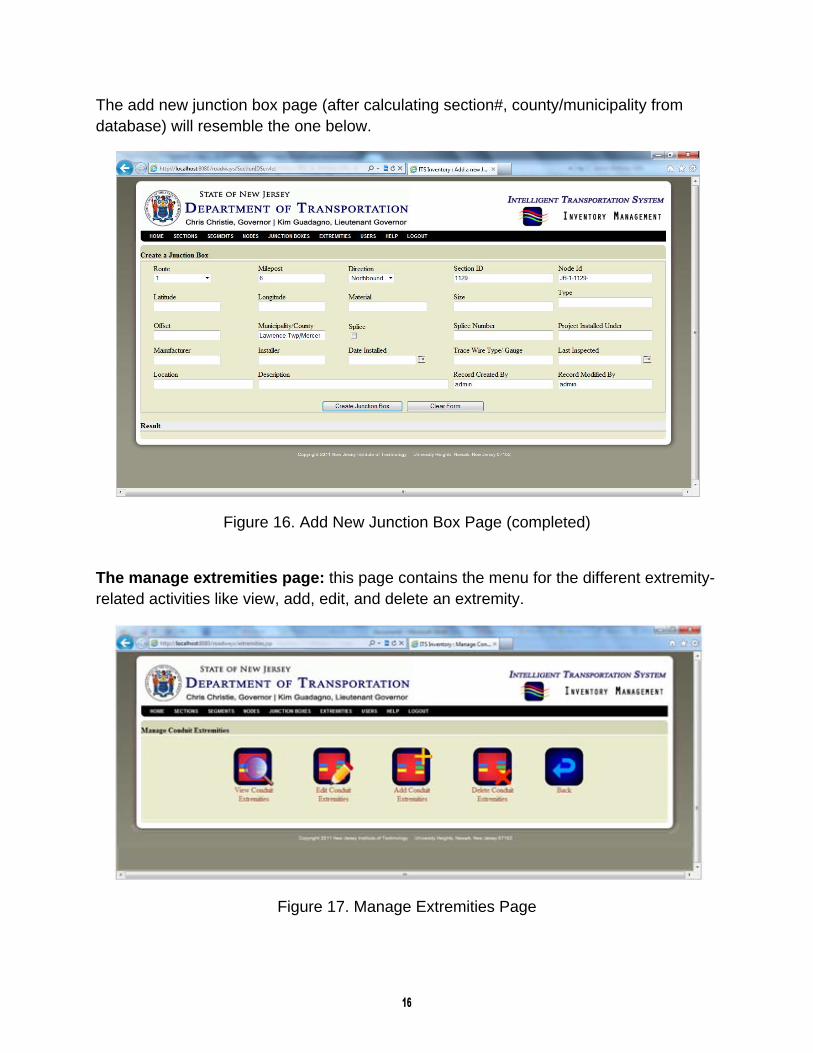
The add new junction box page (after calculating section#, county/municipality from database) will resemble the one below.
Figure 16. Add New Junction Box Page (completed)
The manage extremities page: this page contains the menu for the different extremity-related activities like view, add, edit, and delete an extremity.
Figure 17. Manage Extremities Page

The manage users page: this page contains the menu for the different user-related activities like view, add, edit, and delete a user.
Figure 18. Manage Users Page
The add user page: this page lets the user create another user account of equal or lower rights. There are two levels of users – those with only view permissions and those with edit permissions. The users without edit permissions do not have access to the create/edit pages mentioned here.
Figure 19. Add User Page

The edit user account page: this page lets the user edit their own account information (first name, last name, etc).
Figure 20. Edit User Account Page
7. ITS JUNCTION BOX DATA ACQUISITION PLAN, TRAINING, AND FIELD INVESTIGATIONS The data for the ITS junction boxes was gathered through field investigations conducted over the course of three and a half months, from July to October 2011. The investigations covered approximately 400 miles of roadway. The locations prioritized for field investigations were as follows:
US Route 1 (Mileposts 0 through 35.89) US Route 1 Business, Mercer County (Mileposts 0 through 2.73) NJ Route 29 (Mileposts 0 through 34.71) NJ Route 30 (Mileposts 0 through 58.26) NJ Route 38 (Mileposts 0 through 19.19) NJ Route 70 (Mileposts 0 through 58.94) NJ Route 73 (Mileposts 0 through 34.64) Interstate 95, Mercer County (Mileposts 0 through 8.77) Interstate 195 (Mileposts 0 through 34.17) Interstate 295 (Mileposts 0 through 67.79) County Route 579, Mercer and Hunterdon Counties (Mileposts 0 through 37.24) County Route 634, Mercer County (Mileposts 0 through 4.93)

We planned to conduct the field investigations by progressing through three phases:
1) Preliminary field investigations: identify junction boxes and determine locations based on milepost, direction, physical setting, and GPS location
2) Training: understand the process for opening junction boxes and identify characteristics of fiber optic cable to track
3) Final field investigations: confirm junction box locations, open junction boxes, create photographic record, and gather data regarding fiber optic cable
Phase 1 was conducted between July 6 and August 15, 2011. Through Phase 1, we were able to identify a significant number of junction boxes on the above roadways that were not on the current NJDOT junction box inventory. We were able to successfully catalog the preliminary information for these boxes outlined in the plan above.
Phase 2 was conducted on August 16, 2011. The training outlined was conducted by Corning Cable Systems (CCS) of Hickory, NC. This company is the primary vendor and installer of fiber optic cable for NJDOT. A full-day training session was conducted by CCS personnel, and was attended by six members of the research team. It covered the following topics:
The purpose and function of different types of fiber optic cable The general installation process of fiber optic cable, including junction boxes Interpretation of fiber optic cable markings for type, length, and size The use of splices and other fiber optic cable equipment
The course was customized based on these topics, and not a standard course offered by CCS. The course outline can be found on the included CD and is labeled ‘Appendix A’.
Phase 3 was conducted from August 18 through October 22, 2011. Some issues were encountered in being able to supplement the inventory for during this phase. These included:
Limited times of availability of crew: This limitation resulted in restrictions in both the number of miles that could be reinvestigated and the range of locations. We were able to reinvestigate a total of approximately 183 miles of road, including US Route 1, US Route 1 Business, SR 29, segments of SR 38, I-195, and I-295.
Limited availability of number of crew members: Because the junction box lids were quite heavy (ranging to over 150 pounds, depending on siting and traffic conditions), opening the junction boxes would have required either a mechanical lifting equipment, which was not available to us, or a minimum of four crew

members, a number which was often not available during Phase 3. At locations that were reinvestigated, but unopened, the exterior of the junction box and its surroundings were photo-logged, and these sites were noted.
Frequency of inclement weather: Several instances of inclement weather during the Phase 3 period, including Hurricane Irene on August 28, 2011, either prevented crews from performing reinvestigations or limited their access to locations due to road closures. Another result of this issue was that, even at locations that were able to be reinvestigated and opened, some junction boxes were inundated with water, making them unable to be examined more closely.
Despite the issues encountered during Phase 3, the following objectives were able to be accomplished over the course of the three phases:
Location data, including GPS coordinates, physical description, roadway, direction, municipality, and county, were recorded for all junction boxes on the prioritized set of roadways.
Training on junction boxes was undertaken by the crew, and the knowledge obtained, while used in only a limited fashion on this task, may be utilized again in the future and passed on.
Photographic records and other data were obtained for a significant portion of the prioritized set of roadways.
The data compiled was key to the development of the junction box database, and strongly supplements the existing NJDOT junction box inventory, which will allow for much more tracking of the ITS fiber optic conduit network. This data, and the corresponding compiled summaries, can be found on the included CD in the folder labeled ‘Appendix B’.
8. CONCLUSIONS AND RECOMMENDATIONS
Through this work, an investigation of the current state of the ITS inventory was conducted. Based on this, a new inventory structure was developed, with a MySQL-based architecture and interface. Also, the ITS database was reviewed, and field investigations were conducted that allowed the database to be updated and supplemented for a number of major state routes.
At this point, the ITS inventory can be populated with both the existing inventory data and data gathered through the current field investigations. However, in order to implement the inventory to its fullest extent, the database would need to be further developed in terms of both the scope and the variety of data. This would allow searches of the ITS network or its components based on both each individual component and on its connectedness to the network as a whole.

Nevertheless, the inventory architecture and interface is currently equipped to allow these types of searches, which would undoubtedly be useful for both NJDOT ITS operations and for other units of NJDOT for whose work the ITS network would either interfere or be involved. Continued testing of the ITS inventory and database should be conducted to ensure that it is providing optimal functionality for its users.