developing guidance and tool support for rationale-based use
TRANSCRIPT

Developing Guidance and Tool Support forRationale-based Use Case Specification
Allen H. Dutoit* and Barbara Paech˚
*Technische Universität München, Institut für Informatik, 80290 Munich, [email protected]
˚Fraunhofer Institute for Experimental Software Engineering, 67661 Kaiserslautern, [email protected]
Abstract. Few requirements engineering techniques are widely applied in indus-try. This can–at least to some extent–be attributed to lack of dedicated guidance,tool support, and technique integration. In this paper, we describe dedicated toolsupport and guidance for rationale-based use case specification, which we incre-mentally derived from several students experiments. Through this example, wewant to promote student experiments as a good basis for developing and improv-ing guidance material and tool support, hence facilitating technology transfer.
1 Introduction
There is a wide variety of techniques for elicitation, specification, validation, andmanagement of requirements, but only few of them are used in industry. For example,at a seminar given last year to around 100 developers in the car industries (suppliersand procurers), 90% of the participants used natural language text edited in MS Wordfor the requirements specification [18]. Also, the experience from several industryprojects the authors were involved in, shows that even the quality of requirementsdocuments that adhere to some standard is often fundamentally flawed, because:• they do not contain the information needed by the people who have to rely on it,• this information is often inconsistent, ill-structured, and imprecise,• the authors of the specification did not find an adequate level of abstraction
avoiding design decisions, but capturing all relevant requirements details.The reasons for these flaws are manifold and typically depend on the context. However,in general, three issues seem to be essential for a successful requirements engineeringprocess:• Detailed guidance for participants. Most techniques suggested from academia are
not sufficiently well explained to be usable by persons other than their inventors. Similarly, this holds true for established techniques like use cases, where, for example, there is almost no guidance regarding the right level of abstraction adequate for certain project contexts.
• Dedicated tool support. Although there exist modeling and requirements management tools, these tools are general purpose and do not support specific tasks. Again, this holds true, for example, for use cases, where there is no dedicated tool support for the capture and management of use cases.
• Smooth integration among the techniques applied. The lack of integration among techniques and with the rest of the process is the most critical of these three issues. For example, there is no integrated method established for the simultaneous usage

of use cases and class models.In this paper, we describe such guidance, tool support, and integration for rationale-based use case specification. Our ultimate research goal is to support the evolution ofsoftware by making available to developers rationale captured during requirements andkept up-to-date throughout the software life cycle [10]. However, before we can worktowards that goal, we first need to understand the details of applying use casespecification and rationale capture to a realistic problem. We have done this bydeveloping a dedicated tool integrating both use case specification and rationalecapture. We have evaluated and refined this tool in the context of case studies conductedwith students in project courses.
Literature about experiments in software engineering (e.g., [2][20]) warns about thethreats to the validity of experiments using student subjects. The main argument is thatthe experience of the subjects in skills that are relevant to the study must berepresentative of the population to which the results will be generalized, which is notalways the case with student subjects. The case studies described here, however, havegiven us much insight on how to improve our approach. They also reinforce the positionabove that guidance and integrated tool support are essential. By evaluating the toolwith students, we have the opportunity to develop and improve guidance material forthe tool and the process. Student experiments, in this case, are especially valuable forderiving guidance because of the general lack of specific experience of students, whichwould have allowed them to apply requirements engineering techniques withoutguidance and integration [2]. Therefore, if the guidance and integration is appropriatefor the students, it will most likely also be appropriate for practitioners.
Thus, the purpose of this paper is twofold: First, we describe dedicated tool supportfor use case specification and rationale capture. Second, with this example, we want topromote the idea of student experiments as a means of refining requirements techniquesand tools with specific guidance and integration, hence facilitating technology transfer.In Sect. 2, we describe our assumptions, the tool we developed, and its evaluationsetting. We discuss the problems encountered with use case specification in Sect. 3, aswell as the guidance we devised to overcome these problems. Similarly, in Sect. 4, wedescribe the problems encountered with rationale capture and the resultingimprovements. In Sect. 5, we describe the problems with the integration and the detailsinvolved in improved integration. The conclusion summarizes the guidance and toolsupport derived from the case studies.
2 Experimental Environment
In [10], we described an integrated process for use case specification and rationalecapture, as well as the requirements for a tool supporting this process. Developers usethe tool for describing a problem statement (we assume a meaningful problem statementhas already been negotiated with the client) and refining the problem statement into arequirements specification. Developers and reviewers have the opportunity for enteringrationale information, as a side effect of specification, collaboration, and review. In thefollowing, we give an overview on the tool (Sect. 2.1) and describe the context for thetwo case studies, a software engineering project course (Sect. 2.2) and a requirementsengineering seminar (Sect. 2.3).

2.1 Tool Overview
The design goals of the first version of the tool were to provide a simple and integratedsolution to manipulate use case and rationale models without embedding processspecific assumptions. The tool is a web application that can be accessed via mostpopular web browsers. This enables users to access the tool remotely from a variety ofenvironments (e.g., lab, home, office) without the installation of additional software.The main view of the tool presents the user with three frames: a title/menubar, arequirements specification view and a rationale view (see Fig. 1.).
The requirements view displays the requirements specification as a hypertextdocument, structured into actors, user tasks, use cases, services, and non-functionalproperties [10]. Actors and user tasks describe the application domain from the user’spoint of view and independently from the system. The services describe the features ofthe system, independently from the user. The use cases describe how user tasks arerealized in terms of services and provide traceability from the problem statement to thespecification. Non-functional properties can be used to describe non-functionalrequirements on the system or to describe facts of the domain that are more easilyexpressed as properties than task descriptions. The user can also provide examples interms of actor instances and scenarios and define important terms using a glossary. Thetool provides templates, text boxes, and selection menus for each requirements element.The tool recognizes known terms and highlights them automatically in text fields (e.g.,the flow of events of a user task or a use case). For example, Fig. 2. displays the detailedview of a use case.
Fig. 1. Overview of tool: requirements specification (left column) and rationale (right column)are allocated the same amount of screen real estate.

In the rationale view, information is structured according to the Questions, Options,Criteria (QOC) paradigm [14] and displayed as tables and hyperlinks, thus maximizingthe density of information that the user can read in a single screen (see Fig. 3.). A singlepage describes the question under consideration, the decision (if any) that resolves thequestion, and a table describing the trade-offs that were evaluated. The rows of the tableare the different options that were considered. The columns of the table are the criteriarelevant to the question that were used to evaluate the options. The table cells containthe assessments of each option against each criteria.
Displaying rationale as text is a different approach than other well-known rationale-based tools (e.g., gIBIS[7], SYBIL[12], QuestMap[19]), which display rationale as agraph. In addition to the QOC structured information, users can annotate questions withinformal comments or arguments (with the [Post Comment] feature) to providereference information or negotiate various aspects of the question.
An important assumption behind our process is that requirements and rationale mustbe tightly integrated for decreasing the overhead of rationale capture and increasing itsutility. This integration is visible in the tool in two ways: the interlinking ofrequirements elements and questions, and the interlinking of non-functional propertiesand criteria.
Linking of requirements and rationale elements. the user can create questionsin two ways: by challenging a specific requirements element with the [Question] featureor by justifying a requirements element with the [Justify] feature (see buttons at the topof the use case view in Fig. 2.). By clicking on [Question], the user is presented a seriesof forms to enter a question, its relevant criteria, one or more options, and theassessments of the options against the criteria. Users use [Question] to request aclarification, express a disagreement, or more generally, to initiate a discussion. Onceother users have contributed to the question and a consensus is reached, the user canclose the question with a decision. By clicking on [Justify], the user is presented with asimilar series of forms, except that the resulting question is closed and the current
Fig. 2. Detailed use case view. The user is provided a template for each requirements elements.Questions can be associated to any element.

alternative is described and used as a decision. The resulting question can only bediscussed if it is first reopened. [Question] is used to open a discussion with multipleusers and hence collaboratively building a rationale behind one or more evolvingrequirements element; while [Justify] is used (usually by a single user) to enter thejustification of the current version of a requirements element.
When creating questions, either with [Question] or [Justify], the tool stores abidirectional link between the questioned requirements element and each of itscorresponding questions. This enables the user to navigate and update related questionsor related elements quickly.
Linking of non-functional properties and criteria. Non-functional propertiesare treated as criteria in the rationale view (Fig. 3.). This enables the user to select non-functional properties that are relevant to a given question. These non-functionalproperties are then included as columns in the assessment table as a regular criteria.Each option can thus be evaluated according to the degree of satisfaction of each non-functional property. Links between the columns in the rationale view and the non-functional properties in the requirements view enables the user to view detaileddescriptions of non-functional properties and their context. Note that, while all non-functional properties correspond to a criteria, not all criteria correspond to a non-functional property. Some criteria, for example, can originate from other tools (e.g.,design goals during system design).
Fig. 3. Detailed question view. Users can collaborate by adding options, criteria, assessments, andreferences to elements.

Finally, the tool has minimal process knowledge, thus to increase the flexibility of thetool and the evaluated processes: Users can manipulate any requirements elements andrationale elements in any order and at any time. Process guidance is provided insteadthrough training and on-line help documentation within the tool.
2.2 STARS Case Study
The tool was first used in the software engineering project course offered at TechnischeUniversität München (TUM) [5]. 22 students divided into four teams developedSTARS (Sticky Augmented Reality Technology System), a prototype augmentedreality application for nuclear powerplant technicians. Three of the four teams (15students) were involved in the requirements engineering of the system, which lastedfive weeks (Fig. 4.).
The students were provided with a nuclear powerplant maintenance scenarioillustrating the use of the STARS system and a general problem statement in terms ofactors, user tasks, and non-functional properties. The instructors spent two lectures onrequirements engineering in general and a 45 minute tutorial on using the tool. Inaddition to the on-line help, the students had access to a toy example describing thespecification for a supermarket check out system. Coaches and instructors providedfeedback to 2D mock-up and on the initial version of the specification during reviewsand using questions in the tool. Students spent the final week of the requirements phaseconsolidating the specification by discussing and answering any remaining openquestions.
We used four different source of data for the evaluation of the tool: logged useractions, user questionnaire, informal comments and discussions about the tool, and thefinal version of the requirements specification and its associated rationale. In using
Fig. 4. Requirements engineering phases and schedule during STARS. Subsequent developmentphases (in gray) included for completeness.
2D paper mock-up
Specification, 1st draftConsolidated specification
System designSystem design consolidation
Build 1
Build 3 (Final)
WeekKickoff
1
Build 2
Delivery
Milestone
23456789
10111213
STARS Requirements Phases

these different data, we focused only on qualitative aspects, as our goal was to uncoverlimitations and elicit ideas for improving the tool and its associated guidance.
The students produced a 24 page requirements specification using the tool, including29 use cases. The quality of the requirements specification was average. For example,several use cases documented system design level features of the system and thegranularity of the use cases was too small. Several weaknesses of the specification(discussed in Sect. 3) were traced to misunderstandings of the process and lack ofdistinctions between user tasks, use cases, and services.
The rationale information included 62 questions (with their associated options,decisions, comments, and criteria), spanning 40 pages of text. About half of thisinformation was related to clarifications and omissions, and thus, would not be usefulinformation downstream for system evolution. While students did understand relativelyeasily the basic concepts of the QOC paradigm, their use of comments and questionssometimes pointed to missing features in the tool (discussed in Sect. 4).
We observed that students used the tool as a mechanism for delivering specificationsand for obtaining feedback from instructors. In some instances, the students used thetool to obtain clarifications from other students about their contribution to thespecification. However, the tool was not used as a collaboration mechanism within theteams. Instead, they used face-to-face meetings and designated a volunteer to enter theirdecisions in the tool. In total, only about 6 students used the full range of thefunctionality provided by the tool.
2.3 Meeting Scheduler Case Study
In the STARS case study, several use cases did not have any questions attached, in otherwords, there was no rationale associated with them. This lead us to add the [Justify]feature for developers to explicitly justifying use cases and services (discussed inSect. 2.1). This feature is similar to the feature for raising questions, except that itproduces only closed questions. This feature was then evaluated in the next case study.
Four students taking a requirements engineering seminar at TUM spent four weeksdeveloping a requirements specification for the meeting scheduler problem [11]. Westructured the original problem statement into three actors, four user tasks, and 10 non-functional properties. The students were already familiar with requirements engineeringmethods and, hence, were given only a 15 minute tutorial on user tasks, use cases, andQOC.
Except for an explicit phase during which students justified their use cases, therequirements phases followed in this case study were the same as in STARS (Fig. 5.).
Fig. 5. Requirements engineering phases during Meeting Scheduler case study.
Use cases, 1st draft
WeekKickoff
1
Milestone
234
Consolidated use casesJustified use casesJustified services, 1st draft
Meeting Scheduler Requirements Phases

Similar to STARS, the students spontaneously decided to meet face-to-face once perweek. The students also met once per week with the instructor (as part of their regularseminar duties), which provided an opportunity for clarifying the process and theconcepts behind the tool. Given the smaller size of the forum and the better systemdevelopment experience of the students, much fewer misunderstandings about theprocess occurred.
The same data collection methods were used as in STARS. This case resulted in aspecification of better quality than STARS, including 20 pages and 18 use cases. Therationale information included 40 questions, including 13 justifications which weremuch likely to be useful during system evolution. Students spent more effort than inSTARS on capturing and structuring this rationale.
3 Supporting Use Case Specification
In both case studies we had given the students a tutorial on user tasks and use cases. Wedid not provide them with a very specific use case template, since it was not ourintention to develop and teach a new use case approach. However, it turned out that thestudents needed more guidance, that the textual representation in the tool was lackingmeans for use case structuring and that the use of non-functional requirements as criteriafor the evaluation of options required more specificity for the non-functionalrequirements specification. In the following, we describe these problems in more detailtogether with planned improvements.
3.1 Use Case Guidance
We had emphasized to students that in use cases the interaction between system andactors should be described. However, the use cases written by the students suffered fromseveral problems, some of them mentioned also in [13]. In particular,
1. the use cases were written from the system´s point of view, 2. the single steps of the flow of events were often indistinguishable, 3. actor names were inconsistent, 4. exceptions were described as separate use cases or omitted5. the students wrote too many small use cases with too little coherence.Another problem was that the difference between user tasks and use cases was not clear.So for example, use cases which described new functionality were added as new usertasks. Therefore, a lot of time planned for review and consolidation of the rationaleactually went into review and consolidation of the form of user tasks and use cases.
To overcome these problems we will provide different templates for user tasks anduse cases. The new templates are shown in Fig. 6 and 7.
The use case template is adapted from the essential use cases of [8], where each usecase step has a number, and actor and system steps have to alternate. This way, we hopeto avoid the first two problems. Explicit naming of actors and exceptions shouldalleviate the third and fourth problem. The includes relationships as well aspreconditions and postconditions can be used to structure the set of use cases, thussupporting coherence between use cases.

We will also provide tool support for filling in the templates. Thus, e.g. the actors canbe selected from the set of actors already defined or a new actor can be created. In thelatter case, this actor is simultaneously included in the list of available actors.
User Task Name Manage Interaction Among Participants
Initiating Actor Meeting Facilitator
Participating Actors Meeting Participant
Task description The Meeting Facilitator is responsible for getting replies fromparticipants who have not reacted promptly, for notifyingparticipants of changes of date or location, and for keepingparticipants aware of current unresolved conflicts or delays in thescheduling process.
Realized in Use Cases Cancel Meeting, Handle Replies, Remind Participant, Set Meeting,React to Replan Request
Fig. 6. User Task Template
Use Case Name Remind Participant
Initiating Actor Meeting Facilitator
Realized User Task
Manage Interaction Among Participants
Participating Actors
Meeting Participants
Flow of events Actors
1. The Meeting Facilitator selects ascheduled meeting and the “RemindParticipant”-Feature.
3. The Meeting Facilitator selects aparticipant.
5. The Meeting Facilitator writes themessage and requests the messagesending.
System
2. The System allows a choicebetween the meeting-participants.
4. The System allows the formulationof the message.
6. The System sends the message tothe selected participant [Exception:Message Fails].
Exceptions [Message Fails] If the System cannot the deliver the message, it notifies theMeeting Facilitator.
Rules Retry Message Sending for 5 hours
Precondition The meeting has been scheduled
Postcondition The meeting participant has been reminded through a message by themeeting facilitator
Includes Use Cases
None.
Used services Message Send
Fig. 7. Use Case Template

3.2 Support for Use Case Structure
To emphasize the structure and coherence of use cases we will encourage students towrite for each user task one complex use case, possibly including other use cases.Another means to support the structure and the “big picture” of the use cases altogether,is to allow for a use case diagram. While it is beyond the scope of the current tool toautomatically link the diagram elements with the specification elements, just providingthe picture will be helpful to understand the overall structure. In addition use cases willbe grouped according to user tasks, and services will be grouped (possibly withduplicates) according to use cases.
3.3 Guidance for Non-Functional Properties
During the case studies it became clear that there are different kinds of non-functionalproperties with different usage as criteria. By making this explicit we hope to focus theoptions, arguments and criteria provided by the students. Thus, we will use the propertytypes described in Table 1. The table also indicates when the different criteria are used.So, for example, domain properties are used as criteria on how well use cases andservices realize a user task.
In some sense these criteria can be viewed as goals for the system design. However,our types are much simpler than goal types in goal-oriented approaches to requirementsengineering (e.g. GBRAM[1] or KAOS[11]). In contrast to these approaches we useuser tasks instead of goals to drive the requirements elicitation and specificationprocess. We only use the non-functional properties as criteria for the evaluation of theadequacy of use case or service design wrt. to user tasks and use cases, respectively.
4 Supporting Rationale Capture
Our ultimate goal is to provide rationale information to developers for supportingevaluation. Currently, we have evaluated how this rationale can be first captured bydevelopers as a side effect of development (entering explicit justifications for specificrequirements elements), collaboration (asking questions and negotiating solutions), and
Table 1. Types of non-functional properties.
Property type ExplanationUsed as criteria in
questions for:
Domain Property
Facts of the domain to be adhered to by the software system (e.g. “a person may not be a two different places”)
Use Cases, Services
Global functional properties
High-level functional requirements that cannot be attributed to single use cases, but affect several use cases (e.g.”the meeting scheduler must in general handle several meetings in parallel”)
Use Cases
Quality requirements
Requirements on characteristics of user tasks, use cases or system services, e.g. “the elapsed time between the determination of a meeting date and location and the communication of this information to all participants concerned should be as small as possible”.
User Tasks, Use Cases, Services

review (requesting changes and pointing out defects by raising questions). In theSTARS case study, the initial version of the tool provided the same mechanism for allthree types of activities, a simple matrix representation based on QOC (see Sect. 2). Inthe Meeting Scheduler case study, we added the [Justify] feature for supporting thecreation of closed questions to better support justification. However, all questionsresulting from the three activities were still represented using QOC.
When examining the questions generated during the case studies, we realized thatQOC is too general a paradigm. Once a question was raised, users often did not knowwhether they should discuss the question, realize the first option, or simply comment onthe relevance of the question. Moreover, for simple cases (e.g., a clarification question),most of the complexity of QOC is not needed (e.g., clarifications do not have alternativeoptions or criteria associated with them).
For the next series of case studies, we are refining the rationale model to address theissues we encountered while supporting justification, collaboration, and review. Inparticular:• Question authors specify the type of question being asked (challenge on form,
challenge on content, clarification, inconsistency, justification, omission, see Table 2.).
• The set of available actions that can be invoked on a question is then restricted based on the type of question. For example, clarification questions can only be closed while challenges on content can have new options, criteria, and assessments.
• The tool provides additional views to filter questions by type. This enables, for example, a rationale maintainer to see only the questions that have potential use for long term rationale.
• Arguments can be attached to assessments in addition to questions. This enables users to focus on specific cells in the assessment matrix. This is critical when the QOC matrix alone does not seem to justify the selected decision. We will also focus on heuristics for specifying and reviewing assessment matrixes in the tutorial.
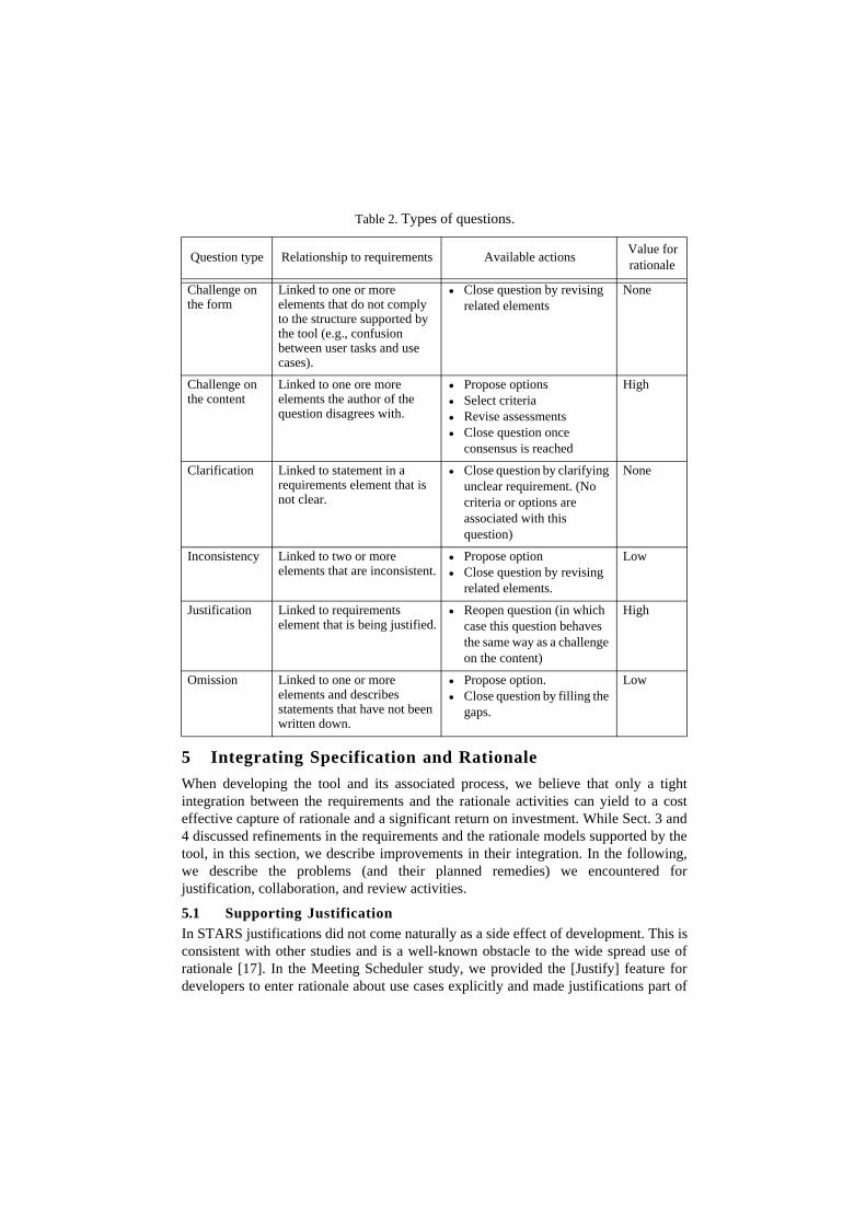
Table 2. summarizes the types of questions, the set of available actions for each type,and the potential value of each type of question for the rationale maintainer.The taxonomy of questions in Table 2. results from the classification of the defects withwhich each question is associated.1 This is a different taxonomy of question than thatused in other rationale-based approaches, such as [3] and [16]. [16] uses a taxonomybased on the type of information missing from the specification (e.g., what-is, how-to,who, what-kinds-of, when) which encouraged reviewers to ask questions by identifyingmissing information, usually the hardest types of defects to identify. [3] uses a domainspecific taxonomy that analysts develop as part of the requirements process. Thisenables stakeholders to identify quickly which questions are relevant to their wincriteria. In our case, we decided to select the defect taxonomy given that our focus is onuse case developers (as opposed to the reviewers or the clients) and provide them moreguidance about what to do with the questions. Moreover, we do not need to create anexplicit domain-based taxonomy as questions are already attached to specificrequirements elements (which can also be glossary entries).
1. With the exception of the Justification type which can be viewed as a subcase of the “Challenge on Content” type.
5 Integrating Specification and Rationale
When developing the tool and its associated process, we believe that only a tightintegration between the requirements and the rationale activities can yield to a costeffective capture of rationale and a significant return on investment. While Sect. 3 and4 discussed refinements in the requirements and the rationale models supported by thetool, in this section, we describe improvements in their integration. In the following,we describe the problems (and their planned remedies) we encountered forjustification, collaboration, and review activities.
5.1 Supporting Justification
In STARS justifications did not come naturally as a side effect of development. This isconsistent with other studies and is a well-known obstacle to the wide spread use ofrationale [17]. In the Meeting Scheduler study, we provided the [Justify] feature fordevelopers to enter rationale about use cases explicitly and made justifications part of
Table 2. Types of questions.
Question type Relationship to requirements Available actionsValue for rationale
Challenge on the form
Linked to one or more elements that do not comply to the structure supported by the tool (e.g., confusion between user tasks and use cases).
• Close question by revising related elements
None
Challenge on the content
Linked to one ore more elements the author of the question disagrees with.
• Propose options• Select criteria• Revise assessments• Close question once
consensus is reached
High
Clarification Linked to statement in a requirements element that is not clear.
• Close question by clarifying unclear requirement. (No criteria or options are associated with this question)
None
Inconsistency Linked to two or more elements that are inconsistent.
• Propose option• Close question by revising
related elements.
Low
Justification Linked to requirements element that is being justified.
• Reopen question (in which case this question behaves the same way as a challenge on the content)
High
Omission Linked to one or more elements and describes statements that have not been written down.
• Propose option.• Close question by filling the
gaps.
Low
the deliverables. While justifications cost additional overhead, we found that there areconcrete incentives for including justifications on use cases. For example, when ajustification was phrased as explaining how a use case satisfies better the non-functionalproperties than other versions of the same use case, missing (non-functional)requirements were found.
Currently, however, non-functional properties can only be created in therequirements view. It is then impractical and unintuitive to create new non-functionalproperties on the fly when writing a justification. We plan to modify [Justify] so thatnon-functional properties can be created as a side effect of writing a justifications. Webelieve this will improve the completeness of the requirements elements by theelicitation of more non-functional properties (especially domain facts) and improve thequality of the rationale information by documenting more accurately the trade-offs thatwere investigated.
5.2 Supporting Collaboration
In both case studies, developers collaborated mostly outside the tool, except for limitedcases of collaboration between different teams. We believe this lack of collaborationthrough the tool was due to two main reasons: First, developers had the opportunity tomeet face-to-face. Second, the tool lacked features typically offered by newsgroups orE-mail. Once a question was posted, it was not always obvious who the target of thequestion was and what actions were expected. Some developers attempted to indicatethis with the [Post Comment] feature, but this was not a common case. We plan toimprove collaboration support within the tool by adding features for asynchronous andsynchronous notification (e.g., by enabling users to send a link to a question via e-mail),and by embedding more information about user responsibilities.
During consolidation, each student (or team) was responsible for resolving the openquestions related to their requirements elements. However, since several questionsrelated to different use cases could interact, developers would have to read all thequestions related to their elements to be able to comprehensively consolidate theirrequirements elements. Since questions could only be viewed by single attributes ofquestions (e.g., requirements element they are related to, time of modification, author,and status), this task was difficult when many questions were still open. We plan to addviews into rationale that are more closely related to how responsibilities are assigned.For example, developers should be able to view all questions related to all requirementselements pertaining to a single user task, or to view all the questions by author of relatedrequirements elements.
We also plan to add a facilitator attribute to questions that can be explicitly set byusers and that can be used to sort questions. The facilitator of a question (which may bethe author of the related requirements elements) is then understood by all users as theperson responsible for facilitating the negotiation about the question, and, onceconsensus is reached, to close the question and revise the related requirements elements.
In general, however, it will not be possible to remove completely the need for face-to-face meeting, in which cases, we still need to capture the important questions thatwere raised during the meeting. This could be done by a minute taker taking notes asQOC matrixes [7][9] or by supporting the post-processing of meetings using QOC [4].

The definition of views could, of course, be alleviated by the use of a general-purposerequirements management tool like DOORS. A first version of the tool had also beenimplemented as a DOORS prototype. However, the effort to turn DOORS into adedicated tool, e.g. with concurrent view of requirements and rationale, specific inputand output templates for use cases and rationale, and especially the assessment matrixwith options, criteria and arguments, was soon deemed too high for our purpose. Also,the students would have needed much more training on DOORS than they need on thecurrent tool.
5.3 Supporting Review
In both case studies, more than half of the questions were generated during review, bythe instructors, the coaches, and the authors. Of these questions, half were request forclarifications and reports of omissions, which, once the requirements specification isrevised to resolve these questions, do not contain much useful rationale information. Wealso found some rationale that was buried in unrelated clarification questions, andjustification questions were often missing assessments and alternative options.Consequently, a hypothetical rationale maintainer would have to spend a substantialeffort filtering, completing, and restructuring this information to be useful duringevolution.
By adding more information about questions, such as the question types described inSect. 4 and the question facilitator described in Sect. 5.2., reviewers will be able tobetter focus their questions and elicit alternative options from specific developers.Moreover, when justifications are written by developers as part of their work, thereviewers will also be able to not only step through the requirements specifications butalso the justification questions. The reviewer can comment on the justifications if non-functional properties are missing or if the assessments provided by the developers arenot clear (with the argument on assessment feature described in Sect. 4). We anticipatethat this will reduce the number of clarification questions while increasing the amountof discussion on the justifications.
6 Conclusion
In this paper, we described tool support for integrated use case specification andrationale capture as well as two case studies where we have evaluated the tool. Theproblems we encountered and the resulting proposed improvements (includingenhanced tool features and improvements to the guidance) are summarized in Table 3.
We will evaluate the tool and its guidance again during the summer in several casestudies using again the meeting scheduler as problem domain. With the input of thesecase studies we hope to have completed the guidance on use case specification andrationale capture, so that we can focus on rationale usage during the winter softwareengineering project course at TUM. To further study collaboration during requirementsengineering, we also plan a distributed case study where students from Kaiserslauternand TUM collaborate for the specification, only by way of the tool.
It is generally recognized that case studies and experiments with students are limitedwhen testing the effectiveness of a method or a tool and for generalizing to thepopulation of software developers. However, we showed, using rationale-based use

case specification as an example, how qualitative case studies using students as subjectscan lead to improvements in both tool support and guidance. To support the claim ofpractical usefulness of the tool, experiments with practitioners have to be carried out.
References[1] A. Anton & C. Potts.”The Use of Goals to Surface Requirements for Evolving Systems,” International
Conference on Software Engineering, pp.157-166, Kyoto, 1998.[2] V.R. Basili, F. Shull, & F. Lanubile. “Building Knowledge through Families of Experiments,” IEEE
Transactions on Software Engineering, vol. 25, no.4, July/August, 1999.[3] B.Boehm, A. Egyed, J. Kwan, D. Port, A. Shah, & R. Madachy, “Using the WinWin Spiral Model: A
Case Study,” IEEE Computer, pp. 33–44, July 1998.[4] A. Braun, B. Bruegge, & A.H. Dutoit. “Supporting Informal Meetings in Requirements Engineering”
Submitted to REFSQ’2001, Interlaken, Switzerland, June 2001.[5] B. Bruegge, A.H. Dutoit, R. Kobylinski, & G. Teubner. “Transatlantic Project Courses in a University
Environment,” Asian Pacific Software Engineering Conference, Singapore, December 2000.[6] S. Buckingham Shum, “Analyzing the Usability of a Design Rationale Notation,” in T.P. Moran & J.M.
Carroll (eds.) Design Rationale: Concepts, Techniques, and Use. Lawrence Erlbaum, Hillsdale, NJ, 1995.
[7] J. Conklin & K. C. Burgess-Yakemovic, “A process-oriented approach to design rationale,” Human-Computer Interaction, vol. 6, pp. 357–391, 1991.
Table 3. Summary of improvements for tool and guidance.
Technique Goal Tool Feature Guidance
Use case specification
Distinction of user task and use case
Differentiated templates for use cases and user tasks
Improved flow of events
Refined use case template Essential use cases
Improved coherence and structuring
Pre- and postconditions, use case diagram
One use case for each user task, inclusion of other use cases
Improved non-functional properties
Property types & restricted application
Restriction of applicability of types as criteria
Rationale capture
Improved response to questions
Question types, restricted actions, question facilitator
Restrictions of actions by question types
Improved assessments
Arguments attached to assessments
Heuristics for reviewing assessments.
Use case/rationale integration
Improved non-functional properties
On the fly creation of criteria during justification
Relationship between non-functional properties and criteria.
Improved collaboration
E-mail notification, list of active users, responsibility-based views, global glossary
Lower maintenance effort
Question typesView by question types
Review process includes review of justification

[8] L.L. Constantine & L.A.D. Lockwood, “Structure and Style in Use Cases for User Interface Design”, to appear in M. van Harmelen (ed.), Object-Oriented User Interface Design, 2001
[9] A. H. Dutoit, B. Bruegge, & R. F. Coyne, “The use of an issue-based model in a team-based software engineering course,” Conference proceedings of Software Engineering: Education and Practice (SEEP’96). Dunedin, New Zealand. January 1996.
[10] A. H. Dutoit & B. Paech, “Supporting Evolution: Rationale in Use Case Driven Software Develop-ment,” In International Workshop on Requirements Engineering: Foundations of Software Quality (REFSQ’2000), Stockholm, June, 2000.
[11] A. van Lamsweerde, R. Darimont & Ph. Massonet. “Goal-directed Elaboration of Requirements for a Meeting Scheduler: Problems and Lessons Learnt”, Int. Symp. on Requirements Engineering, pp. 194-203, 1995
[12] J. Lee, “A qualitative decision management system,” Artificial Intelligence at MIT: Expanding Fron-tiers. P.H Winston & S. Shellard (eds.) (MIT Press, Cambridge, MA,) Vol. 1, pp. 104–133, 1990.
[13] S. Lilly, “Use Case Pitfalls: Top 10 Problems from real Projects using Use Cases, Technology of object-oriented languages and systems, pp. 174-183, 1999
[14] A. MacLean, R. M. Young, V. Bellotti, & T. Moran, “Questions, options, and criteria: Elements of de-sign space analysis,” Human-Computer Interaction, vol. 6, pp. 201–250, 1991.
[15] T. P. Moran & J. M. Carroll (eds.), Design Rationale: Concepts, Techniques, and Use. Lawrence Erl-baum Associates, Mahwah, NJ, 1996.
[16] C. Potts, K. Takahashi, & A. I. Anton, “Inquiry-based requirements analysis,” IEEE Software, vol. 11, no. 2, pp. 21–32, 1994.
[17] S. B. Shum & N. Hammond. “Argumentation-based design rationale: what use and what cost? Interna-tional Journal Human-Computer Studies, 40:603-652.
[18] Seminar “Steuergeräte-Design im Automobilbau und in der Industrieautomation”, Haus der Technik, Essen, 24.-25.5.2000
[19] The Softbicycle Company. QuestMap: The Wicked Problem Solver. http://www.softbicycle.com/. [20] M.V. Zelkowitz & D.R. Wallace. “Experimental Models for Validating Technology” IEEE Computer,
May, 1998.