designing self-healing superhydrophobic surfaces with ... · cleaning,1 drag-reducing,2...
TRANSCRIPT
Designing Self-Healing Superhydrophobic Surfaces with ExceptionalMechanical DurabilityKevin Golovin,†,⊥,# Mathew Boban,‡,⊥,# Joseph M. Mabry,¶ and Anish Tuteja*,†,‡,§,⊥
†Department of Materials Science and Engineering, ‡Department of Macromolecular Science and Engineering, §Department ofChemical Engineering, and ⊥Biointerfaces Institute, University of Michigan, Ann Arbor, Michigan 48109, United States¶Rocket Propulsion Division, Air Force Research Laboratory, Edwards Air Force Base, Edwards, California 93524, United States
*S Supporting Information
ABSTRACT: The past decade saw a drastic increase in the understanding andapplications of superhydrophobic surfaces (SHSs). Water beads up and effortlesslyrolls off a SHS due to its combination of low surface energy and texture. Whetherbeing used for drag reduction, stain repellency, self-cleaning, fog harvesting, or heattransfer applications (to name a few), the durability of a SHS is critically important.Although a handful of purportedly durable SHSs have been reported, there are stillno criteria available for systematically designing a durable SHS. In the first part ofthis work, we discuss two new design parameters that can be used to developmechanically durable SHSs via the spray coating of different binders and fillers.These parameters aid in the rational selection of material components and allow oneto predict the capillary resistance to wetting of any SHS from a simple topographicalanalysis. We show that not all combinations of sprayable components generate SHSs, and mechanically durable components donot necessarily generate mechanically durable SHSs. Moreover, even the most durable SHSs can eventually become damaged. Inthe second part, utilizing our new parameters, we design and fabricate physically and chemically self-healing SHSs. The mostpromising surface is fabricated from a fluorinated polyurethane elastomer (FPU) and the extremely hydrophobic small molecule1H,1H,2H,2H-heptadecafluorodecyl polyhedral oligomeric silsesquioxane (F-POSS). A sprayed FPU/F-POSS surface canrecover its superhydrophobicity even after being abraded, scratched, burned, plasma-cleaned, flattened, sonicated, and chemicallyattacked.
KEYWORDS: superhydrophobic, wettability, durability, self-healing, coatings
■ INTRODUCTION
Superhydrophobic surfaces (SHSs) have garnered muchattention over the last few decades for their ability to be self-cleaning,1 drag-reducing,2 stain-resisting,3 and antifouling.4 Bytrapping pockets of air in their porous texture, SHSs displaywater contact angles >150° and low roll-off angles.5 The designand optimization of such surfaces have been well studied.1−17
However, most natural and artificial SHSs suffer from poormechanical durability, as their fragile and porous surface texturecan be easily removed even by the swipe of a finger.12 Only afew SHSs have been reported to exhibit mechanical durability,as characterized by sand impact,18−22 rubbing with a softcloth,3,23−25 tape peel tests,7,19,26−28 or sandpaper abra-sion.9,12,14−16,19,24,29−40 However, all such reports presentsingle material systems. The development of design criteria toaid in the systematic fabrication of durable SHSs, generalizableto multiple chemistries or fillers, is expected to be extremelyuseful to the field. In the first part of this work, we aim todevelop such criteria.Even the most durable SHSs will eventually become
damaged by extreme or repeated mechanical abrasion, whichdamages their low surface energy or texture. SHSs that canregenerate their surface texture and chemistry,41−43 akin to thelotus leaf’s ability to regenerate its nanostructured wax,1 would
be highly desirable. Herein, we also report mechanically durableSHSs that exhibit physical and chemical self-healing. Thedeveloped surfaces can fully recover their water-repellency evenafter being abraded, scratched, burned, plasma cleaned,flattened, sonicated, and chemically attacked. These surfaces,and the design parameters used to develop them, may findimmediate usage in a wide range of academic and industrialsectors across the globe.
■ DESIGNING A DURABLE SHS: CHEMISTRY ANDMISCIBILITY
The lowest possible surface energy, γSV, is achieved with amonolayer of −CF3 groups (γSV ≈ 6 mN/m).44 Chemicallygrafting such monolayers requires specific substrate chemistry.Moreover, the thin monolayer only renders the uppermostsurface hydrophobic, and any surface degradation will exposethe higher surface energy material underneath. In contrast, theincorporation of highly perfluorinated compounds within acoating allows one to achieve equally low surface energies
Received: December 5, 2016Accepted: March 7, 2017Published: March 7, 2017
Research Article
www.acsami.org
© 2017 American Chemical Society 11212 DOI: 10.1021/acsami.6b15491ACS Appl. Mater. Interfaces 2017, 9, 11212−11223

without the need for chemical grafting.45,46 Moreover, theseunbound species can diffuse to the surface, restore the lowsurface energy after mechanical or chemical attack (discussedlater), and reduce the formation of hydrophilic defects upondamage.12 Such coatings can be universally applied to anysubstrate and impart low surface energy throughout the entirethickness of the coating. In this work, we fabricated a library ofSHSs using sprayed blends of polymeric binders and hydro-phobic fillers. Because of its low surface energy (γSV ≈ 10 mN/m), we primarily focus on systems incorporating1H,1H,2H,2H-heptadecafluorodecyl polyhedral oligomeric sil-sesquioxane (F-POSS),45 although the developed designparameters are generalizable to other material systems, asshown here. Spray coating was chosen as the primarymethodology for the application of the superhydrophobiccoatings. Spray coating is inexpensive, scalable, and allowscontrol over the surface energy and texture of our coatings viasimple changes in experimental parameters.As the fillers used in this work are soluble small molecules
rather than nondeformable particles, they cannot induce texture
directly. We observed the microscale texture formation duringspray coating to be strongly dependent on the miscibilitybetween the binder and filler components. Chemically similarblends yielded smooth, nonsuperhydrophobic coatings, butvery chemically dissimilar blends yielded highly superhydro-phobic, but mechanically fragile coatings (discussed later). Thismotivated the quantitative study of the miscibility and itsrelation to durable superhydrophobicity.The cohesive energy of any material species can be broken
into its dispersive, polar, and hydrogen bonding Hansensolubility parameters, (δD, δP, δH).
47 A miscibility sphere can beexperimentally constructed for any compound, with its centerat some point in a 3D space defined by these three solubilityparameters, and its volume encompassing all good solvents andexcluding all nonsolvents. We determined the miscibilityspheres for several hydrophobic fillers and a wide variety ofbinders (Figure 1a) by screening their solubility in a largenumber of solvents (Supporting Information, Tables S1−S3).The overlap between the Hansen spheres of the binder andfiller is indicative of their chemical similarity and the extent to
Figure 1. Designing SHSs. (a) Visualization of the S* parameter for three binders in 3D Hansen space. FO-POSS: fluorooctyl polyhedral oligomericsilsesquioxane. FPU: fluorinated polyurethane. F-POSS: fluorodecyl polyhedral oligomeric silsesquioxane. (b) Apparent receding contact angleversus the P* parameter. The sharp transition at P* = 1.0 denoted a Young’s contact angle of 120°. (c) Measured and predicted apparent advancingcontact angles versus the developed statistical porosity parameter. This plot includes all the different systems from Table 1. The inset shows a SEMmicrograph of the FPU/F-POSS sprayed surface, with representative RSm and Sal values indicated. (d) Phase diagram for all the surfaces developed inthis work (see Table 1). Only surfaces with P* < 1.0 can be superhydrophobic (θroll‑off < 15°, 25 μL), and additionally only surfaces with 0 < S* < 1.0can be mechanically durable (θroll‑off < 15° after 100 abrasion cycles). The non-SHS that exhibited P* < 1.0 was a blend of FPU/FO-POSS. For thisblend, θ = 91°, although the sprayed texture required θc = 114°. This is an example where the texture is sufficient to produce a SHS, but thechemistry does not exhibit low enough surface energy.
ACS Applied Materials & Interfaces Research Article
DOI: 10.1021/acsami.6b15491ACS Appl. Mater. Interfaces 2017, 9, 11212−11223
11213

Table 1. Surface Properties of Coatings in This Work before and after 100 Rotary Taber Abrasion Cycles
base % F-POSS P* D*statinitial
θ*adv [°]initial
θ*rec [°]initial
θroll‑off [°]100 cycleθ*adv [°]
100 cycleθ*rec [°]
100 cycleθroll‑off [°]
100 cycle massloss [%]
Neverwet 1.79 7.4 165 162 1 132 37 54 17Ultra Ever Dry 1.36 4.0 161 152 1 155 0 90 14Cytonix WX 2100 1.04 1.4 164 156 18 122 77 90 6FPU (S* = 0.64) 0 1.84 7.2 115 66 55FPU 1 0.99 14.3 106 67 90 106 63 90 1FPU 3 1.49 25.5 121 66 90 122 78 76 3FPU 5 0.31 1.5 148 112 62 151 102 75 8FPU 10 0.34 2.5 162 150 10 159 124 22 20FPU 15 0.48 3.9 165 159 2 161 154 2 32FPU 20 0.56 3.5 163 153 5 161 144 10 40FPU 25 0.67 6.4 166 153 2 164 152 2 86FPU 30 0.68 4.8 165 160 2 163 144 3 81FPU 35 0.63 4.4 160 151 1 146 113 24 56FPU-PG (S* = 1.06) 5 0.62 5.3 163 145 8 153 98 81 44FPU-PG 10 0.57 8.2 161 152 7 158 116 57 40FPU-PG 15 0.75 4.7 162 148 7 161 113 90 27FPU-PG 20 0.74 5.6 164 151 3 159 123 40 26PMMA (S* = 1.17) 0 1.06 5.1 155 0 90PMMA 2 0.76 5.5 160 83 14 135 0 90 109PMMA 5 0.43 4 160 143 11 159 123 35 99PMMA 10 0.58 3.4 163 153 7 159 128 24 104PMMA 35 0.90 5.9 166 156 2 162 127 26 129PMMA 50 0.86 4.2 164 156 0 127 84 63 100SF-100 (S* = 0.74) 0 1.99 2.9 93 37 64SF-100 5 1.38 3 129 41 90SF-100 10 1.75 2.9 140 72 83SF-100 15 1.27 4.5 158 123 13 167 113 37 22SF-100 20 1.01 3.8 163 157 1 165 133 21 30SF-100 25 0.92 3.5 169 163 0 166 164 1 55SF-100 35 0.60 7 167 159 2 145 107 34 38PDMS (S* = 0.32) 0 1,88 3.8 123 45 90PDMS 15 0.73 5.4 154 119 47 158 137 10 20PDMS 30 0.55 5.4 160 153 4 157 0 66 46PFPE (S* = 0.46) 0 1.88 18.6 113 78 53PFPE 5 2.12 0.5 127 66 66PFPE 15 1.08 7 155 72 47 163 20 90 45PFPE 25 0.55 3.7 156 147 7 163 142 8 33PFPE 35 0.58 4.1 165 153 2 164 0 90 100Vytaflex (S* = 1.60) 0 2.00 1 73 4 90Vytaflex 1 1.52 9.6 149 0 90Vytaflex 5 1.08 4.5 150 0 90Vytaflex 10 1.15 3.1 135 29 90Vytaflex 15 0.65 4.5 158 134 11 159 55 39 28Vytaflex 35 0.55 5.2 160 150 2 161 130 17PS 45 (S* = 0.48) 0 1.15 26.6 157 123 14PS 45 15 0.60 1.9 157 131 14 156 114 37 26PS 45 25 0.58 1.4 155 142 15 152 111 38 14PS 1.2 (S* = 0.48) 15 0.94 8.5 159 153 0 100PIB (S* = 0.19) 0 1.27 19.3 118 61 90PIB 15 1.18 10.4 164 143 14 161 118 90 48Araldite (S* = 0.23) 0 1.95 2.9 101 17 90Araldite 5 1.94 12.5 128 43 90 127 62 87Araldite 15 1.39 1 137 43 90 132 69 90 3Araldite 25 0.89 9 158 130 14 158 16 90 25Desmophen 670BA(S* = 0.91)
0 1.43 41.9 85 49 90 0
Desmophen 670BA 2.5 0.52 8.9 161 141 8 148 94 74 17Desmophen 670BA 5 0.36 7.8 166 157 5 159 125 23 20Desmophen 670BA 10 0.38 8.4 166 160 4 162 129 16 24Desmophen 670BA 15 0.17 2.3 165 156 9 164 162 2 27
ACS Applied Materials & Interfaces Research Article
DOI: 10.1021/acsami.6b15491ACS Appl. Mater. Interfaces 2017, 9, 11212−11223
11214
which they phase separate and form texture during the spray-coating process. To quantify a polymer’s miscibility with thefiller, we developed the miscibility parameter S*, which is givenas
* =Δ − +
SR R R
R2binder filler
filler (1)
Here, ΔR is the distance in 3D solubility space between thecenters of the filler’s sphere and the binder’s sphere, with theirradii denoted by Rfiller and Rbinder, respectively.Similar to Hansen’s relative energy difference47 value, S* is
defined such that the filler is completely immiscible with abinder when the two spheres do not overlap (S* > 1.0, also seeschematic in Figure 1a). Alternately, binders with S* < 0 havesolubility spheres that completely encompass the filler’s sphereand are hence fully miscible (at a given concentration, seeFigure S5). In between these two extremes is the regime ofpartial miscibility, which turns out to have far-reachingconsequences for the sprayed superhydrophobic surface’sdurability.The S* parameter allows one to predict if the filler will phase
separate from the binder during spray coating. This phaseseparation manifests in the sprayed surface’s root−mean−squared roughness, Sq. For example, we determined thesolubility spheres for a polyurethane and an epoxy, which areboth commonly used hydrophilic adhesives (Tables S2 and S3).For the epoxy, S* ≈ 0.2 with F-POSS, and an epoxy+5 wt % F-POSS blend, when sprayed, resulted in a smooth surface withSq = 0.8 μm. Conversely, for the polyurethane, S* ≈ 1.6, and apolyurethane+5 wt % F-POSS blend, when sprayed in the exactsame manner (methods), resulted in a very rough surface (Sq =41 μm). Thus, immiscibility alone can induce roughness duringthe spray coating process. However, a large Sq does notguarantee superhydrophobicity.48
■ DESIGNING A SHS: SURFACE TEXTUREWater on SHSs can exist in the Cassie−Baxter state, in whichair pockets are trapped in the surface’s porous texture.49
However, water can displace these air pockets, which leaves thesurface in a wetted, Wenzel state.50 SHSs should ideally bedesigned such that the Cassie−Baxter state is energeticallypreferred.1 We developed a method to predict when theCassie−Baxter state would be energetically favorable over theWenzel state using only the topographical statistics of a givensurface. Because each binder/filler combination exhibited adistinct, characteristic surface morphology, we wished todevelop universal metrics that characterize surfaces with widelyvarying topographies. To do so, we measured three statisticalsurface properties (methods): peak periodicity, RSm, autocorre-lation length, Sal, and Wenzel roughness, r (the ratio of theactual surface area to its projected area).50 RSm represents thelength along the surface between large surface features and canbe thought of as the center-to-center distance between textureelements.51 Sal denotes the length at which a surface no longerexhibits self-similarity and can be thought of as the average sizeof the largest texture features. We, therefore, can define thestatistical porosity Dstat* of the surface as (inset, Figure 1c)
* =D RS S( / )m alstat2
(2)
where the second power is added to convert from propertiesmeasured along one-dimensional height profiles to the porosityof a two-dimensional surface.11 Larger values of Dstat* indicatesurfaces with higher porosity.For the Cassie−Baxter state to be favored over the wetted
Wenzel state, it must be the global energy minimum.52 For agiven surface topography, the free energies of the two states canbe balanced. The nonwetted state is energetically preferred onlyif the Young’s contact angle of the material, θ, exceeds a criticalvalue, θc. This critical Young’s contact angle is given by cos θc =(ϕs − 1)/(r − ϕs),
52 where ϕs is the fraction of solid in contact
Table 1. continued
base % FO-POSS P* D*statinitial θ*adv
[°]initial θ*rec
[°]initial θroll‑off
[°]100 cycleθ*adv [°]
100 cycleθ*rec [°]
100 cycleθroll‑off [°]
100 cycle massloss [%]
FPU(S* = 0.44)
15 0.81 8.9 141 66 90 137 68 90 4
FPU 25 0.53 7.2 163 149 9 161 124 30 12FPU 35 0.48 7.0 162 153 4 162 146 14 15
base % IB-POSS P* D*statinitial
θ*adv [°]initial
θ*rec [°]initial
θroll‑off [°]100 cycleθ*adv [°]
100 cycleθ*rec [°]
100 cycleθroll‑off [°]
100 cycle massloss [%]
FPU (S* = 0.31) 25 0.41 5.1 165 130 15 140 75 90 9FPU 30 0.31 4.9 164 144 5 165 132 15 17Desmophen 670BA(S* = 0.37)
2.5 0.52 5.7 139 57 90 129 46 90 5
Desmophen 670BA 5 0.36 8.6 158 96 81 137 46 90 8Desmophen 670BA 10 0.35 6.6 164 142 13 160 66 90 20Desmophen 670BA 15 0.38 7.8 163 139 14 150 91 61 16Desmophen 670BA 25 0.28 5.8 165 148 8 165 136 15 21Desmophen 670BA 30 0.27 5.8 166 151 10 165 155 6 24
base % eico-sane P* D*statinitial θ*adv
[°]initial θ*rec
[°]initial θroll‑off
[°]100 cycle θ*adv
[°]100 cycle θ*rec
[°]100 cycleθroll‑off [°]
100 cycle massloss [%]
CNR(S* = 0.29)
0 2.00 18.3 93 78 90
CNR 25 1.45 11.3 157 82 84CNR 30 1.00 3.5 162 87 71CNR 35 0.74 4.3 153 141 14 162 92 33 2CNR 40 0.80 3.4 148 137 15 163 113 38 3CNR 50 0.94 6.5 160 146 11 164 77 90 11
ACS Applied Materials & Interfaces Research Article
DOI: 10.1021/acsami.6b15491ACS Appl. Mater. Interfaces 2017, 9, 11212−11223
11215
with water (note Dstat* ≈ ϕs−1). Stated differently, by recalling
that Young’s water contact angles cannot exceed 120° even on afully perfluorinated monolayer,10 there exists some minimaltexture that any surface, regardless of surface chemistry, mustexhibit to achieve an energetically favorable Cassie−Baxterstate. Substituting this maximum contact angle as θc yields
θ = = * − − *◦ D r Dcos cos 120 (1/ 1)/( 1/ )c stat stat
or
− = − * * −D rD0.5 (1 )/( 1)stat stat
We can then define a surface’s superhydrophobic potential, P*,such that only for values of P* < 1.0 is the Cassie−Baxter statethe global energy minimum. Doing so yields
* = * − * −P D rD2( 1)/( 1)stat stat (3)
For any surface that exhibits P* > 1.0, the wetted state isenergetically preferred, regardless of surface chemistry. Notethat water can exist in a metastable Cassie−Baxter state throughthe addition of re-entrant texture,10 and hence, a value of P* >1.0 does not necessarily indicate wetting. P* is useful becausesurfaces are often created with a given topography and thensubsequently rendered superhydrophobic by application of alow surface energy layer on top.1 As such, measuring P* allowsone to determine a priori if such a surface will becomesuperhydrophobic before such a (often expensive) low surfaceenergy monolayer is applied. Moreover, if a surface issuperhydrophobic in spite of a P* > 1.0 value, one can saywith certainty that water will exist in a metastable state, andsuch a surface should be used with caution. By measuring thedynamic contact angles on many surfaces, both wetted andnonwetted, we probed the effectiveness of P*.
When water initially advances on a SHS, it displays amaximum apparent contact angle, θadv* .53 If any texture elementsbecome wetted, the apparent angle at which water recedes, θrec* ,will decrease. Thus, θadv* is a measure of the SHS’s inherentporosity (i.e., fraction of air pockets), ignoring how stable theair pockets may be, and θrec* gives an indication of theirstability.54 We measured θrec* for more than 50 combinations ofF-POSS and various polymeric binders, as a function of P*(Figure 1b). These binders included both cross-linkednetworks, such as different urethanes, acrylates, epoxies, andcyanoacrylates, as well as linear polymers such as polystyrene,poly(methyl methacrylate) and polyisobutylene (Methods,Table 1). We observed a high θrec* only for systems with astable Cassie−Baxter state, that is, P* < 1.0. This was confirmedby the sharp jump in θrec* at a value of P* = 1.0. The specificvalue of P* = 1.0, corresponding to a Young’s contact angle θ ≈120°, indicated that all the surfaces had a high percentage of F-POSS at the solid−liquid interface, although there were vastdifferences in topography. Thus, we were able to predict if an F-POSS-containing surface could be superhydrophobic solely bymeasuring P*. Without measuring P*, there is no easy way todetermine if a randomly textured surface has the potential tobecome superhydrophobic, a priori. Moreover, for surfaces withP* < 1.0, recasting the Cassie−Baxter relation49 in terms of Dstat*effectively predicted θadv* (Figure 1c). We observed that thepredictive power of Dstat* and P* extended to other SHSs notcontaining F-POSS. These SHSs included polymer blends withother hydrophobic fillers like eicosane, octa-isobutyl POSS (IB-POSS), and fluoro-octyl POSS (FO-POSS), as well as otherSHSs such as three commercially available superhydrophobicformulations (Methods, Tables S1−S3), lithographicallyfabricated microstructures,55 textured metals treated with self-assembled monolayers,56,57 and binders filled with hydrophobic
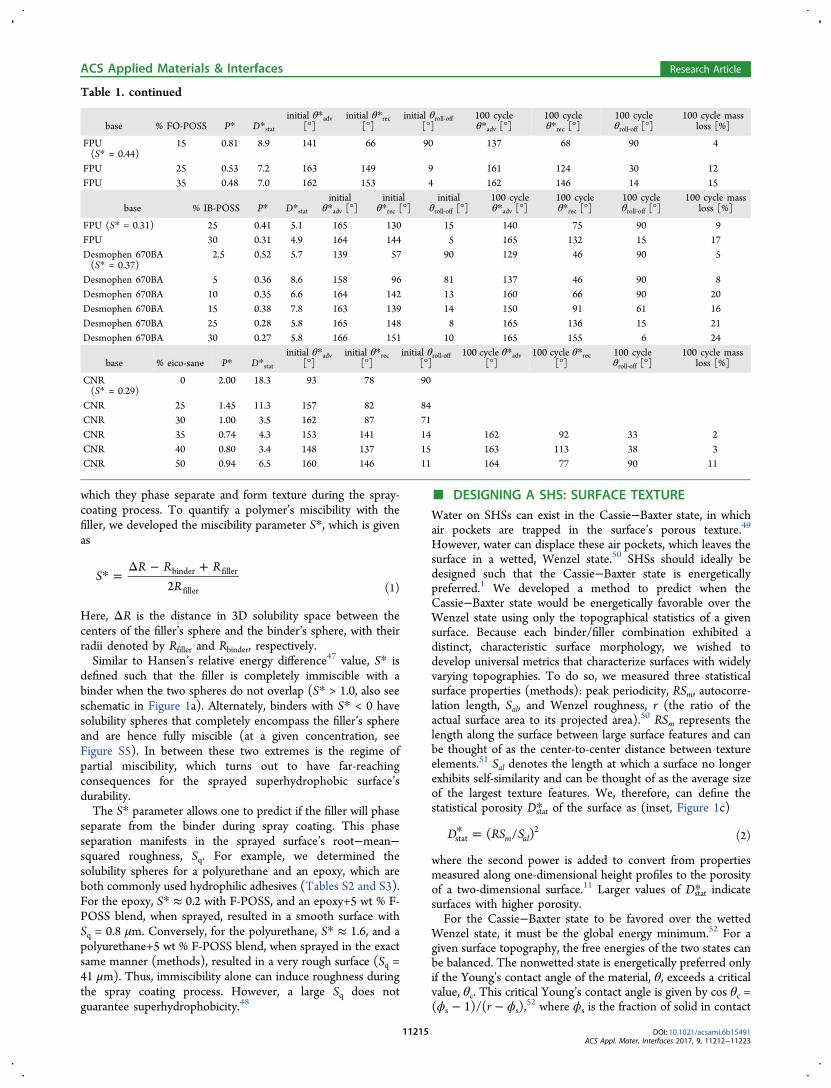
Figure 2. Mechanical durability. (a) Shear stress experienced during Taber abrasion as a function of depth into the coating. The values are foundusing Hertzian contact mechanics (see Supporting Information). The inset shows the Taber abrasion machine. (b) Additional durabilitycharacterizations that the FPU/F-POSS coating could withstand without self-healing. (c) Roll-off angles for three commercially available SHSs andeight of the SHSs fabricated in this work (with S* < 1.0), initially and after 100 abrasion cycles. C, chlorinated rubber; F, FPU; D, Desmophen670BA; S, SF-100; P, PFPE. (d) Droplet roll-off angles for four representative, durable SHSs fabricated in this work. The data for the propyleneglycol chain extended FPU/F-POSS and the self-healed FPU/F-POSS are also shown. All roll-off experiments used 25 μL droplets.
ACS Applied Materials & Interfaces Research Article
DOI: 10.1021/acsami.6b15491ACS Appl. Mater. Interfaces 2017, 9, 11212−11223
11216

particles.58 As such, the design parameters developed in thiswork are applicable to SHSs produced using a wide range ofbinders, fillers, and fabrication techniques.For each binder (fixed S*), we varied P* by adjusting the
amount of hydrophobic filler in the blend. Combining the S*and P* parameters allowed us to construct a phase diagram forthe different possible surfaces created when spraying thebinder/filler blends (Figure 1d). Here we denote surfaces witha red “×” when the water roll-off angle was θroll‑off > 15° (notsuperhydrophobic) and surfaces that exhibited θroll‑off < 15°(superhydrophobic) as blue squares. These two regions weredemarcated by a line at P* = 1.0, that is, we never observed aSHS for which P* > 1.0.Low surface energy species are known to preferentially
migrate to the solid−air interface.59 For binders with S* > 1.0,the final surface was always very mechanically weak, with apowdery consistency, because the filler was completelyimmiscible with such binders. Green circles in Figure 1ddenote surfaces that remained superhydrophobic after mechan-ical abrasion (discussed later). These mechanically durableSHSs were only observed when a binder exhibited partiallymiscibility with the filler (S* < 1.0), that is, we never observed adurable SHS with S* > 1.0. Finally, we note that increasing theamount of filler within a sprayed blend was not alwaysefficacious. As the binder can be much more mechanicallyresilient than the filler molecules, any excess filler within theblend, beyond what is required to achieve superhydrophobicity(P* < 1.0), can lower the overall durability. For example, aperfluorinated polyether, PFPE, with 25 wt % F-POSSremained superhydrophobic after abrasion, but PFPE with 35wt % F-POSS did not, although the S* and P* values wereequivalent. Overall, choosing components that satisfy S* < 1.0helps to ensure that the final surface will be durable, andchoosing a sufficient filler content such that P* < 1.0 assuresthat the surface will be highly water repellent.
■ DURABILITY OF SHSS: MECHANICAL ABRASIONWe utilized the industry standard of rotary Taber abrasion toevaluate the mechanical durability of our sprayed binder/fillerblends. The stresses generated by Taber abrasion can be foundusing a cylinder−cylinder Hertzian contact mechanics analysis(Figure S2).60 Depending on the elastic modulus of the coating,the exerted shear stress ranged from tens to hundreds of kPa(Figure 2a). Considering the porosity of the surface, the textureelements experienced shear stresses on the order of a few MPa.This is similar or greater than the less systematic durabilitycharacterization techniques employed in the litera-ture.9,12,14−16,19,24,29−40 For example, in a recent report,16 theauthors’ durable SHS was abraded with sandpaper along a totallength of 800 cm, without degradation of high contact angle.We reproduced such an evaluation for our FPU/F-POSS blend,which maintained high contact angles, as well as low roll-offangles, even after 1 km (100 000 cm) of abrasion using thesame sandpaper and applied load (Figure 2b, Figure S2b).Thus, we have good confidence in claiming that the surfacescreated in this work can also withstand the other metrics ofmechanical durability reported elsewhere.One-hundred Taber abrasion cycles sufficiently differentiated
durable and nondurable SHSs, that is, nondurable surfaces wereeither completely removed or water wet the remaining coating,after 100 abrasion cycles. Only surfaces that exhibited θroll‑off <15° after 100 abrasion cycles are shown as green circles inFigure 1d. All such surfaces exhibited partial miscibility with the
hydrophobic fillers (0 < S* < 1.0). We then continued Taberabrasion of our partially miscible blends (Table 1). Wecompared the durability of these systems to three commerciallyavailable, and purportedly durable, SHSs (Figure 2c). None ofthe commercial coatings maintained a low θroll‑off after 100abrasion cycles. We extended the abrasion testing of ourbinder/filler blends exhibiting S* < 1.0 and found them to bequite resilient to mechanical wear (Figure 2d). Although allother evaluated SHSs became wettable within 100 abrasioncycles, the nonwetting properties of our surfaces enduredsignificantly longer. When blended with F-POSS, coatingsincorporating the PFPE, SF-100, and FPU binders remainedsuperhydrophobic for up to about 400, 500, and 800 Taberabrasion cycles, respectively. Combinations of the polyurethaneDesmophen 670BA and IB-POSS or the FPU and FO-POSSboth exhibited θroll‑off < 15° for ∼800 cycles. In fact, all suchsystems only became wettable once almost the entire coatingwas abraded away. For example, a 100 μm-thick FPU/F-POSScoating maintained θroll‑off < 15° even when > 90 μm of itsthickness was removed. Note that the coating mass loss was notlinear with the number of abrasion cycles; large aggregates wereremoved first. Abrasion of smooth FPU/F-POSS blends andother partially miscible systems (S* ≈ 0.4−0.9), deposited byalternate means (Methods), confirmed that the abrasionprocess did not induce superhydrophobicity (P* ≈ 1.3−1.9)after abrasion (see Figure S3). Rather, only the SHSs fabricatedfrom partially miscible components maintained P* < 1.0(Figure 2d, Figure S4) during abrasion, whereas fully miscible(S* < 0) and fully immiscible (S* > 1.0) systems did not.As further proof that partial miscibility is required for
mechanically durable SHSs, we chain extended the FPU byincorporating propylene glycol into the cross-linked network(Methods). The chain-extended FPU exhibited a three-foldincrease in elastic modulus and a 12% reduction in mass lossduring abrasion of the smooth binder (no F-POSS), ascompared to unmodified FPU. However, the increased numberof urethane linkages altered the Hansen sphere for the cross-linked network by changing the miscibility with F-POSS fromS* ≈ 0.6 to S* ≈ 1.1. As such, although a sprayed blend of FPU+15 wt % F-POSS (P* = 0.48) remained superhydrophobicafter 800 abrasion cycles, a sprayed blend of the chain extendedFPU+15 wt % F-POSS (P* = 0.56) was no longersuperhydrophobic after only 100 abrasion cycles (Figure 2d).This counterintuitive result emphasizes the fact that the binderwith the correct miscibility (0< S* < 1.0), not the mostmechanically durable binder, can yield the most mechanicallydurable SHSs. Moreover, the blend of FPU/F-POSS alsowithstood a host of other potentially damaging exposures(Methods). After ultrasonication, a fluoro-solvent rinse, acidand base submersion, knife scratching (Movie 3), acceleratedweathering, ultraviolet exposure, and being held at 350 °C for 3days, the coating always maintained θroll‑off < 10° (Methods,Figure 2b).
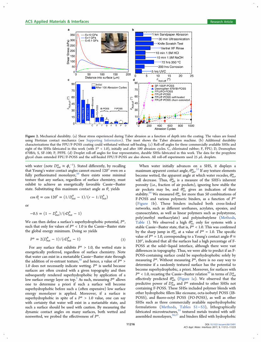
■ PHYSICAL AND CHEMICAL SELF-HEALING SHSSIn the remainder of this work, we focus on our most durablecoating, the FPU binder blended with 15 wt % F-POSS.Because of the surface migration of F-POSS upon heating andthe elastomeric (Tg ≪ room temperature) nature of the FPU,the fabricated coating can both chemically and physically self-heal. For example, the as-abraded coating maintained θroll‑off <15° up to about 800 abrasion cycles. Beyond this, θroll‑offincreased with the number of abrasion cycles. However, if the
ACS Applied Materials & Interfaces Research Article
DOI: 10.1021/acsami.6b15491ACS Appl. Mater. Interfaces 2017, 9, 11212−11223
11217
coating was placed on a hot plate for a few minutes, the waterrepellency was easily restored (θroll‑off < 5°, Figure 3a). Withself-healing, the FPU/F-POSS coating maintained θroll‑off < 15even after 4000 abrasion cycles. Other blends created usingdifferent elastomers, such as SF-100/F-POSS, FPU/FO-POSS,or Desmophen 670BA/IB-POSS, also exhibited a self-healingnature. The self-healing and superhydrophobic nature ofDesmophen 670BA/IB-POSS system is notable because neitherof the components contains any fluorinated species.The low surface energy of F-POSS causes it to migrate to the
solid/air interface59 and impart different binder/F-POSS blendswith a robust, self-healing nature. For example, oxygen plasma,which has the capability of hydrolyzing F-POSS,61 rendered theFPU/F-POSS coating hydrophilic within minutes (θ* = 0°,although P* remained unchanged). However, upon heating, the
low surface energy was fully restored (Figure 3b). We foundthat the time required for full superhydrophobic recoverydecreased with increasing temperature, consistent with adiffusion-controlled process. The coating maintained low θroll-offwhen held at temperatures up to about 400 °C, the point atwhich F-POSS begins to degrade (Figure 3c). However, evenwhen >75% of the mass had degraded, the coating maintainedθroll‑off < 15°. We also repeatedly treated the coating with O2plasma and found that the water repellency was fully recoveredby heating even after 10 successive treatments (Figure 3d).Even after mechanical wear, a robust SHS should also exhibit
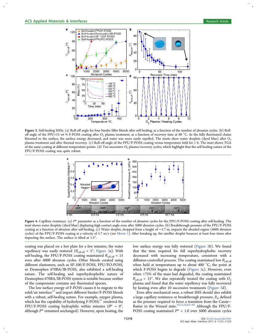
a large capillary resistance or breakthrough pressure, Pb, definedas the pressure required to force a transition from the Cassie−Baxter to the Wenzel state.10,11,52,62−64 Although the FPU/F-POSS coating maintained P* < 1.0 over 5000 abrasion cycles
Figure 3. Self-healing SHSs. (a) Roll-off angle for four binder/filler blends after self-healing, as a function of the number of abrasion cycles. (b) Roll-off angle of the FPU+15 wt % F-POSS coating after O2 plasma treatment, as a function of recovery time at 80 °C. As the fully fluorinated chainsbloomed to the surface, the surface energy decreased, and water was more easily repelled. The insets show water droplets (dyed blue) after O2plasma treatment and after thermal recovery. (c) Roll-off angle of the FPU/F-POSS coating versus temperature held for 1 h. The inset shows TGAof the same coating at different temperature points. (d) Ten successive O2 plasma/recovery cycles, which highlight that the self-healing nature of theFPU/F-POSS coating was quite robust.
Figure 4. Capillary resistance. (a) P* parameter as a function of the number of abrasion cycles for the FPU/F-POSS coating after self-healing. Theinset shows water droplets (dyed blue) displaying high contact angle even after 5000 abrasion cycles. (b) Breakthrough pressure of the FPU/F-POSScoating as a function of abrasion after self-healing. (c) Water droplet, dropped from a height of ∼1.7 m, impacts the abraded region (4000 abrasioncycles) of the FPU/F-POSS coating at a velocity of 5.7 m/s (see Movie 1). After breaking up, the satellite droplet bounces at least four times afterimpacting the surface. The surface is tilted at 1.5°.
ACS Applied Materials & Interfaces Research Article
DOI: 10.1021/acsami.6b15491ACS Appl. Mater. Interfaces 2017, 9, 11212−11223
11218

(Figure 4a), indicating an energetically favorable Cassie−Baxterstate, a pressure-induced wetting transition is usuallyirreversible without some form of energy input.10
To evaluate the breakthrough pressure, we completelysubmerged our self-healed FPU/F-POSS coating in apressurized water tank and observed when wetting occurred(Methods). The breakthrough pressure of this coating wasinitially Pb = 100 ± 20 kPa and never decreased below Pb = 50kPa, even after 5000 abrasion cycles (Figure 4b). Remarkably,the pressure resistance increased to a maximum of Pb = 310 kPaafter 4000 abrasion cycles due to the decrease in Sq withincreasing abrasion. As such, even water droplets impinging theabraded surface at an impact velocity of ∼6 m/s completelyrebounded, which left the surface dry (Figure 4c and Movie 1).The maximum measured breakthrough pressure of 310 kPacorresponds to a droplet impact velocity of ∼25 m/s (Pimpact =ρV2/2) and a static water height of 31 m. Although often SHSsonly maintain high contact angle after mechanical damage, thesurfaces reported here preserve all their advantageous, water-repellant properties (high θ*, θroll‑off < 15°, high Pb) even afterharsh mechanical abrasion.The thermal recovery of low surface energy due to F-POSS
migration will only result in a SHS if the texture is alsomaintained. Although abrasion damages the texture of theFPU/F-POSS coating, we found that the abraded texture wasstill sufficient for superhydrophobicity (Figure 4a). Further, wealso observed that the texture could be partially restored duringthe thermal treatment. For example, after 1000 abrasion cycles,the FPU/F-POSS coating exhibited Sq = 2.6 μm. Thermalrecovery at 100 °C for 120 s increased this value to Sq = 3.3 μm(measured at identical locations) (Figure 5a). Thus, abrasionalso slightly compressed the coating. To further explore this, wesubjected the coating to compressive stresses up to 350 MPa.Although flattening the texture elements significantly reducedthe coating’s porosity (P* ≈ 2.0, Figure 5b), such damage wasreversible, and upon heating, the coating quickly recovered its
original porous state (P* ≈ 0.6) (Figure 5b,c). Environmentalscanning electron microscopy (ESEM) allowed us to observethis self-healing in situ (Figure 5d, Movie 2). As thecompression set of elastomers is typically nonzero,65,66 theuse of elastomeric materials in the fabrication of SHSs may beadvantageous in terms of their ability to recover fromcompressive stresses that flatten their porous texture, asshown here.
■ CONCLUSIONIn summary, we have explored how miscibility betweenhydrophobic fillers and polymeric binders allows one to controlthe formation of surface texture during spray coating tofabricate superhydrophobic surfaces. The S* parameterquantifies the miscibility between the two sprayable compo-nents, and the P* parameter characterizes the stability of thenonwetted state. Superhydrophobic surfaces should bedesigned such that S* < 1.0 to afford mechanical durabilityand P* < 1.0 to provide a robust nonwetting state. Utilizingthese two design criteria, we have fabricated superhydrophobicsurfaces with unprecedented mechanical durability. Some ofthese surfaces also exhibited a self-healing nature, bothchemically and physically, and were able to fully recover theirsuperhydrophobicity after a wide variety of extreme chemicaland physical exposures. These surfaces, and the designparameters used to develop them, may find immediate usagein a wide range of academic and industrial sectors across theglobe.
■ METHODSMaterials. All solvents, prepolymers, and cross-linking agents were
used as-received. Fluorinated solvents HCFC-225ca/cb (Asahiklin-225, Asahi Glass Co.) and HFC-43−10mee (Vertrel XF, DuPont)were purchased from Techspray and TMC Industries, Inc.respectively. Poly(methyl methacrylate) (PMMA), polystyrene (PS,45 kDa or 1.2 kDa), and polyisobutylene (PIB) were purchased from
Figure 5. Texture recovery. (a) Self-healing properties of the FPU/F-POSS coating as a function of time and temperature, after 1000 Taber abrasioncycles. Sq increased from 2.6 to 3.3 μm during self-healing. (b) Contact angle hysteresis for the FPU/F-POSS coating before and after thermalrecovery from compression, as a function of the compressive load. Note that the compressed coating’s hysteresis decreased with an increase inapplied load because the surface became smoother after compression. All compressed surfaces were fully wetted. (c) Height maps of the FPU/F-POSS coating after 150 MPa compression, as a function of recovery time at 100 °C. (d) Recovery of the texture was also imaged in situ using ESEM(Movie 2).
ACS Applied Materials & Interfaces Research Article
DOI: 10.1021/acsami.6b15491ACS Appl. Mater. Interfaces 2017, 9, 11212−11223
11219

Scientific Polymer. Luxecolor 4FVBA fluorinated polyol resin (55%solids in n-butyl acetate) was purchased from Helicity Technologies,Inc. Desmophen 670BA polyol was provided by Bayer Materi-alScience, A.G. Isocyanate cross-linkers Desmodur N3200 andWannate HMDI (4,4′-diisocyanato-methylenedicyclohexane) wereprovided by Bayer MaterialScience, A.G. and Wanhua ChemicalGroup Co., Ltd. respectively. Cross-linker ratios were 9.7 and 3.4 wt %,respectively, with FPU and 28.5 wt % N3200 with 670BA. Propyleneglycol, a chain-extending agent that increases the modulus of the finalcross-linked polyurethane network, was obtained from MP Bio-medicals, LLC. A polyurethane elastomer (Vytaflex 40) was purchasedfrom Smooth-On, Inc. and was prepared according to manufacturerdirections. CNR (chlorinated polyisoprene) was provided byCovestro. Polydimethylsiloxane elastomer (Dow Corning Sylgard184) was obtained from Krayden, Inc., and a 10:1 base/cross-linkerratio was used according to manufacturer directions. Acrylate-terminated perfluoropolyether resin (CN4001, purchased fromSartomer USA, LLC) was mixed with 5 wt % radical photoinitiator(Irgacure 2022, provided by BASF Corporation) to yield a UV-curablefluorinated polymer matrix. Cyanoacrylate adhesive (3 M Scotch-WeldSF100) was purchased from Pack-n-Tape, Inc. Two-part epoxyadhesive (Selleys Araldite 90 s) was used in an approximate 1:1volume ratio of the components per manufacturer instructions.Fluorodecyl and fluorooctyl polyhedral oligomeric silsesquioxanes
(F-POSS, FO-POSS) were prepared by condensing perfluorinatedtriethoxysilanes as previously reported.45 Octaisobutyl polyhedraloligomeric silsesquioxane (IB-POSS) was purchased from HybridPlastics, Inc. Eicosane was purchased from Acros Organics.Coating Sample Fabrication. Spray coating solutions were
prepared by solubilizing the filler, polymer, or prepolymer, and cross-linker or photoinitiator (if applicable) at an overall solutionconcentration of 100 mg/mL. The weight fraction of filler in thetotal solution was varied from 0 to 50%. The solvents used for F-POSSand FO-POSS blends were pure Vertrel XF (for FPU and PFPE), pureAK-225 (for SF100, 670BA, PMMA, chain-extended FPU, andPDMS), 50:50 chloroform/Vertrel XF (for Vytaflex 40, PS andAraldite epoxy), and 50:50 AK-225/hexane for PIB. Pure chloroformwas used for IB-POSS blends with 670BA and FPU. Pure toluene wasused for blends of eicosane and CNR.No significant effect on spray coating morphology was observed
between these solvents, as they have similar volatility and surfacetension. The solutions were applied to 10 cm × 10 cm 6061 aluminumsheets with an ATD Tools 6903 high-volume−low-pressure spray gun.Twenty milliliters of coating solution was applied to each plate, whichresulted in coatings that were approximately 100 μm thick. However,because the surfaces are both porous and extremely rough, thethickness could not be well-defined, and during abrasion tests, themass % lost was tracked instead. Spray-coated samples were held atroom temperature for at least 1 day and then cured as necessary priorto further testing (polyurethanes, 80 °C 2 days; PDMS, 150 °C 1 h;epoxy and cyanoacrylate, room temperature at least 2 h; PFPE acrylateresin, 15 min simultaneous exposure to 254 and 365 nm UV mercurylamp irradiation under N2 atmosphere).Hansen Solubility Parameter Studies. Hydrophobic filler
miscibility in the polymer binders was analyzed with the aid of theHSPiP software package and associated database of Hansen solubilityparameters. All solvents were used without further purification,including acetone, THF, chloroform, ethylene glycol, toluene,cyclohexane, hexane, dodecane, DMSO, ethanol, n-butyl acetate,MEK, and o-fluorotoluene (Fisher) as well as 1-hexanol, chloroben-zene, perfluorodecalin, hexafluorobenzene, p-chlorobenzotrifluoride,diisopropylamine, and pentafluorobutane (Sigma-Aldrich). Addition-ally, DI water, AK-225, and Vertrel XF were used.Cross-linked polymers and elastomers were swollen in a selected
number of solvents until a consistent mass was achieved. Samples wereweighed, and then the solvent was extracted using a vacuum oven at100 °C. The goodness of a solvent was determined by ranking theswelling ratio (divided by the mass of the solvent) from 1 to 6, with 1being solvents that swell the polymer the most. These were then inputinto the HSPiP software to determine the center and radius of the
given system or to determine other solvents necessary to better definethe radius of the Hansen sphere.
The Hansen sphere for F-POSS was determined only usingfluorinated solvents, as the fluorine−fluorine interaction is crucial insolubilizing the highly fluorinated compound.45 As an example,hexafluorobenzene and dodecane have the exact same Hansenparameters and similar molecular volumes. However, F-POSS iscompletely insoluble in dodecane even at 1 mg/mL, whereas F-POSSis soluble up to 800 mg/mL in hexafluorobenzene. Thus, rather thanconfounding the results by including alkanes and other proximalmolecules, only fluorinated solvents were used.
Along similar lines, the Hansen sphere for F-POSS was found forvarious solution concentrations. Although the Hansen radius is knownto be weakly dependent on concentration,43 we found a strongdependence when we evaluated fluorinated systems such as F-POSS(Figure S5b,c).
Wettability Measurements. Advancing and receding contactangle measurements were obtained via the sessile drop method using aRame-Hart 200 F1 contact angle goniometer. A water dropletsuspended from a vertical dispensing needle was brought into contactwith the substrate, and its volume increased and decreased to obtainthe advancing and receding contact angles. A circular drop profile onthe live video feed in the DROPImage Advanced software was used toobtain contact angle data. At least three points were measured for eachsurface at each abrasion condition. Droplet roll-off angles wereobtained by placing at least five 25 μL water droplets distributed acrossthe surface with a micropipette and using the manual tilting stage ofthe goniometer to gradually increase the angle. The tilt angle wasrecorded when each droplet rolled off, and the average across thedroplets was calculated. Droplets that did not roll off were recorded asθroll‑off = 90° for averaging purposes. The large error bars in some ofthe abraded samples in Figure 2 arose from averaging areas that wetwith areas that remained superhydrophobic.
Abrasion Testing. Abrasion testing based on ASTM standardD4060 was performed with a Taber Model 5135 Rotary Abraser withCS-10 resilient abrasive wheels. Two-hundred-fifty gram weights wereplaced on the rear of the wheel arms such that the applied normal loadwas ∼60 g, and the sample was then rotated relative to the freelyspinning abrasion wheels such that a shearing abrasion actionoccurred. Excess debris was removed continuously with a vacuumnozzle. The result was a circular region on the sample that wasconsistently mechanically damaged.
The manual sandpaper abrasion test performed previously16 wasautomated using a Taber Model 5750 Linear Abraser. A 2.5 cm × 2.5cm spray coated sample was mounted facing downward on thereciprocating head, and brought in contact with 240 grit sandpaper,with an applied load of ∼250 g. The sample was then moved underload on the static sandpaper, and the test was continued until waterdroplets were pinned. Water roll-off angles were measured periodicallyto confirm the retention of superhydrophobicity (Figure S2b).
Imaging and Metrology. Scanning electron micrographs wereobtained with a Philips XL30 SEM after the samples were sputtercoated with gold to reduce charging effects. Two-dimensional height-maps (2.4 mm × 2.4 mm) of the surfaces were obtained with anOlympus LEXT OLS4000 3D Laser Measuring Microscope with the10× objective, and at least five were collected for each sample at eachabrasion condition. These data were subsequently analyzed to yieldstatistical topographical parameters using MATLAB (see SupportingInformation: Justification of Statistical Parameters).
Thermal Degradation Analysis. A sample of FPU+15 wt % F-POSS was placed on a hot plate at temperatures from 150−425 °C inincrements of 25 °C, 1 h per temperature point. After each bakingstep, the advancing, receding, and roll-off angles were measured(Figure 3c). To correlate the onset of degradation of the Cassie−Baxter state with chemical degradation of the sample, thermogravi-metric analysis was performed with a TA Instruments Discovery SeriesTGA using a 6 mg sample scraped from the same spray-coated surface.This sample was heated from 25−600 °C at 10 °C/min in a 10 mL/min N2 gas purge flow while its mass was continually monitored (inset,Figure 3c).
ACS Applied Materials & Interfaces Research Article
DOI: 10.1021/acsami.6b15491ACS Appl. Mater. Interfaces 2017, 9, 11212−11223
11220

UV Exposure. A sample of FPU+15 wt % F-POSS was placedunder 254 nm UVC mercury lamp (UVP, LLC) at a distance of 5 cm.The contact angles were measured after 5 h of continuous exposure.O2 Plasma Exposure. A sample of FPU+15 wt % F-POSS was
exposed to O2 plasma (Harrick Plasma PDC-001) using RF sourcepower of 30 W and a pressure of ∼200 mTorr for 20 min. Contactangles were measured to verify the complete wetting of the surface. Torecover the water repellency, the coated surface was placed on a hotplate at a certain temperature (80 or 150 °C). For the time-dependentrecovery, the substrate was removed from the hot plate after temporalincrements, and the contact angles were measured. For the O2 plasmacycling, the substrate was placed on a 150 °C hot plate for 20 minbefore contact angles were measured. The O2 plasma exposurefollowed by the 150 °C recovery is denoted as one cycle in Figure 3d.Corrosion Testing. Corrosion testing was done in accordance to
ASTM B117. Briefly, steel tabs measuring 25 mm × 75 mm werespray-coated with the FPU+15 wt % F-POSS coating. The coatedpieces were hung in a salt-spray fog chamber (Bemco Inc.) kept at 35°C for 200 h. A 25 mm scratch was made along the length of thecoating so that the steel underneath was exposed. After the acceleratedcorrosion, the contact angles were measured.Compression Testing. Compression testing was done using a
Carver 4350 compression molder with a 30 ton capacity. Samples ofknown dimensions were placed between aluminum plates, and acertain force was applied and held for 60 s. The contact angles werethen measured immediately following compression. The coating wasthen self-healed on a 100 °C hot plate for 5 min, and contact angleswere recorded again.Breakthrough Pressure Testing/Droplet Impact. Pressure
stability was measured both statically and dynamically. Static pressuretesting was done using a pressure tank (TCP Global) with a 7 cm headof DI water. The pressure was regulated using compressed air. Sampleswere submerged, and the pressure was raised to the set level for 60 s ata ramp rate of no more than 5 psi per second. After the pressure wasreleased, samples were removed to determine if they remained dry.Because of the inhomogeneity of the surfaces, breakthrough wasconsidered to have occurred when the sample was fully wetted uponremoval from the water tank.Dynamic pressure testing was done using impacting water droplets
and a high-speed camera (Fastec Imaging HiSpec 1) at 2000 fps. Thebreakthrough pressure was considered when the droplet becamepinned on the surface upon impact. As the maximum droplet heightfor our experimental setup was 1.7 m, corresponding to an impactvelocity of 5.7 m/s, many surfaces exhibited breakthrough pressurestoo high to measure using droplet impact.
■ ASSOCIATED CONTENT*S Supporting InformationThe Supporting Information is available free of charge on theACS Publications website at DOI: 10.1021/acsami.6b15491.
Additional text, tables, and figures (PDF)Movie 1 (AVI)Movie 2 (AVI)Movie 3 (AVI)Movie 4 (AVI)
■ AUTHOR INFORMATIONCorresponding Author*E-mail: [email protected] Tuteja: 0000-0002-2383-4572Author ContributionsK.G. and M.B. contributed equally. The manuscript was writtenthrough contributions of all authors. All authors have givenapproval to the final version of the manuscript.
Author Contributions#Kevin Golovin and Mathew Boban contributed equally to thismanuscript.
NotesThe authors declare no competing financial interest.
■ ACKNOWLEDGMENTS
We would like to thank Dr. Charles M. Hansen for theinsightful comments. We thank Dr. Ki-Han Kim and the Officeof Naval Research (ONR) for financial support under GrantNo. N00014-12-1-0874. We also thank Dr. Charles Y. Lee andthe Air Force Office of Scientific Research (AFOSR) forfinancial support under Grant Nos. FA9550-15-1-0329 andLRIR-12RZ03COR. We also thank the National ScienceFoundation and the Nanomanufacturing program for support-ing this work through Grant No. 1351412. K.G. thanks theDepartment of Defense (DoD) for a National Defense Science& Engineering Graduate (NDSEG) Fellowship.
■ REFERENCES(1) Bhushan, B.; Jung, Y. C. Natural and Biomimetic ArtificialSurfaces for Superhydrophobicity, Self-Cleaning, Low Adhesion, andDrag Reduction. Prog. Mater. Sci. 2011, 56 (1), 1−108.(2) McHale, G.; Newton, M. I.; Shirtcliffe, N. J. ImmersedSuperhydrophobic Surfaces: Gas Exchange, Slip and Drag ReductionProperties. Soft Matter 2010, 6 (4), 714.(3) Liu, Y.; Liu, Z.; Liu, Y.; Hu, H.; Li, Y.; Yan, P.; Yu, B.; Zhou, F.One-Step Modification of Fabrics with Bioinspired Polydopamine@Octadecylamine Nanocapsules for Robust and Healable Self-CleaningPerformance. Small 2015, 11, 426−431.(4) Genzer, J.; Efimenko, K. Recent Developments in Super-hydrophobic Surfaces and Their Relevance to Marine Fouling: AReview. Biofouling 2006, 22 (5), 339−360.(5) Tuteja, A.; Choi, W.; McKinley, G. H.; Cohen, R. E.; Rubner, M.F. Design Parameters for Superhydrophobicity and Superoleopho-bicity. MRS Bull. 2008, 33 (8), 752.(6) Im, M.; Im, H.; Lee, J.-H.; Yoon, J.-B.; Choi, Y.-K. A RobustSuperhydrophobic and Superoleophobic Surface with Inverse-Trapezoidal Microstructures on a Large Transparent FlexibleSubstrate. Soft Matter 2010, 6 (7), 1401.(7) Maitra, T.; Antonini, C.; Auf der Mauer, M.; Stamatopoulos, C.;Tiwari, M. K.; Poulikakos, D. Hierarchically Nanotextured SurfacesMaintaining Superhydrophobicity Under Severely Adverse Conditions.Nanoscale 2014, 6 (15), 8710−8719.(8) Rykaczewski, K.; Osborn, W. A.; Chinn, J.; Walker, M. L.; Scott,J. H. J.; Jones, W.; Hao, C.; Yao, S.; Wang, Z. How Nanorough isRough Enough to Make a Surface Superhydrophobic During WaterCondensation? Soft Matter 2012, 8 (33), 8786.(9) Shen, L.; Qiu, W.; Liu, B.; Guo, Q. Stable SuperhydrophobicSurface Based on Silicone Combustion Product. RSC Adv. 2014, 4(99), 56259−56262.(10) Tuteja, A.; Choi, W.; Ma, M.; Mabry, J. M.; Mazzella, S. A.;Rutledge, G. C.; McKinley, G. H.; Cohen, R. E. DesigningSuperoleophobic Surfaces. Science 2007, 318 (5856), 1618−1622.(11) Tuteja, A.; Choi, W.; Mabry, J. M.; McKinley, G. H.; Cohen, R.E. Robust Omniphobic Surfaces. Proc. Natl. Acad. Sci. U. S. A. 2008,105 (47), 18200−18205.(12) Verho, T.; Bower, C.; Andrew, P.; Franssila, S.; Ikkala, O.; Ras,R. H. Mechanically Durable Superhydrophobic Surfaces. Adv. Mater.2011, 23 (5), 673−678.(13) Wang, F.; Yu, S.; Ou, J.; Xue, M.; Li, W. Mechanically DurableSuperhydrophobic Surfaces Prepared by Abrading. J. Appl. Phys. 2013,114 (12), 124902.(14) Wu, L.; Zhang, J.; Li, B.; Fan, L.; Li, L.; Wang, A. FacilePreparation of Super Durable Superhydrophobic Materials. J. ColloidInterface Sci. 2014, 432, 31−42.
ACS Applied Materials & Interfaces Research Article
DOI: 10.1021/acsami.6b15491ACS Appl. Mater. Interfaces 2017, 9, 11212−11223
11221
(15) Zhu, X.; Zhang, Z.; Men, X.; Yang, J.; Wang, K.; Xu, X.; Zhou,X.; Xue, Q. Robust Superhydrophobic Surfaces with MechanicalDurability and Easy Repairability. J. Mater. Chem. 2011, 21 (39),15793.(16) Lu, Y.; Sathasivam, S.; Song, J.; Crick, C.; Carmalt, C.; Parkin, I.Robust Self-Cleaning Surfaces that Function when Exposed to EitherAir or Oil. Science 2015, 347 (6226), 1132−1135.(17) Tian, X.; Verho, T.; Ras, R. H. Moving SuperhydrophobicSurfaces Toward Real-World Applications. Science 2016, 352 (6282),142−143.(18) Jiang, W.; Liu, H.; Wang, L.; Zhu, S.; Yin, L.; Shi, Y.; Chen, B.;Ding, Y.; An, N. An Effective Route for Transparent and Super-hydrophobic Coating with High Mechanical Stability. Thin Solid Films2014, 562, 383−388.(19) Zhang, Y.; Ge, D.; Yang, S. Spray-Coating of SuperhydrophobicAluminum Alloys with Enhanced Mechanical Robustness. J. ColloidInterface Sci. 2014, 423, 101−107.(20) Deng, X.; Mammen, L.; Butt, H. J.; Vollmer, D. Candle Soot asa Template for a Transparent Robust Superamphiphobic Coating.Science 2012, 335 (6064), 67−70.(21) Aytug, T.; Simpson, J. T.; Lupini, A. R.; Trejo, R. M.; Jellison, G.E.; Ivanov, I. N.; Pennycook, S. J.; Hillesheim, D. A.; Winter, K. O.;Christen, D. K.; et al. Optically Transparent, Mechanically Durable,Nanostructured Superhydrophobic Surfaces Enabled by SpinodallyPhase-Separated Glass Thin Films. Nanotechnology 2013, 24 (31),315602.(22) Li, Y.; Chen, S.; Wu, M.; Sun, J. All Spraying Processes for theFabrication of Robust, Self-Healing, Superhydrophobic Coatings. Adv.Mater. 2014, 26 (20), 3344−3348.(23) Wang, H.; Liu, Z.; Zhang, X.; Lv, C.; Yuan, R.; Zhu, Y.; Mu, L.;Zhu, J. Durable Self-Healing Superhydrophobic Coating withBiomimic “Chloroplast” Analogous Structure. Adv. Mater. Interfaces2016, 3 (15), 1600040.(24) Chen, L.; Sun, X.; Hang, J.; Jin, L.; Shang, D.; Shi, L. Large-ScaleFabrication of Robust Superhydrophobic Coatings with High Rigidityand Good Flexibility. Adv. Mater. Interfaces 2016, 3 (6), 1500718.(25) Infante, D.; Koch, K. W.; Mazumder, P.; Tian, L.; Carrilero, A.;Tulli, D.; Baker, D.; Pruneri, V. Durable, Superhydrophobic,Antireflection, and Low Haze Glass Surfaces Using Scalable MetalDewetting Nanostructuring. Nano Res. 2013, 6 (6), 429−440.(26) Li, J.-H.; Weng, R.; Di, X.-Q.; Yao, Z.-W. Gradient and WeatherResistant Hybrid Super-Hydrophobic Coating Based on FluorinatedEpoxy Resin. J. Appl. Polym. Sci. 2014, 131 (20), 40955−40962.(27) Barthwal, S.; Kim, Y. S.; Lim, S. H. Mechanically RobustSuperamphiphobic Aluminum Surface with Nanopore-EmbeddedMicrotexture. Langmuir 2013, 29 (38), 11966−11974.(28) Lee, E. J.; Kim, J. J.; Cho, S. O. Fabrication of PorousHierarchical Polymer/Ceramic Composites by Electron Irradiation ofOrganic/Inorganic Polymers: Route to a Highly Durable, Large-AreaSuperhydrophobic Coating. Langmuir 2010, 26 (5), 3024−3030.(29) Su, F.; Yao, K. Facile Fabrication of Superhydrophobic Surfacewith Excellent Mechanical Abrasion and Corrosion Resistance onCopper Substrate by a Novel Method. ACS Appl. Mater. Interfaces2014, 6 (11), 8762−8770.(30) Yin, L.; Yang, J.; Tang, Y.; Chen, L.; Liu, C.; Tang, H.; Li, C.Mechanical Durability of Superhydrophobic and Oleophobic CopperMeshes. Appl. Surf. Sci. 2014, 316, 259−263.(31) Dyett, B. P.; Wu, A. H.; Lamb, R. N. Mechanical Stability ofSurface Architecture-Consequences for Superhydrophobicity. ACSAppl. Mater. Interfaces 2014, 6 (21), 18380−18394.(32) Esteves, A. C. C.; Luo, Y.; van de Put, M. W. P.; Carcouet, C. C.M.; de With, G. Self-Replenishing Dual Structured SuperhydrophobicCoatings Prepared by Drop-Casting of an All-In-One Dispersion. Adv.Funct. Mater. 2014, 24 (7), 986−992.(33) Ma, J.; Zhang, X. Y.; Wang, D. P.; Zhao, D. Q.; Ding, D. W.; Liu,K.; Wang, W. H. Superhydrophobic Metallic Glass Surface withSuperior Mechanical Stability and Corrosion Resistance. Appl. Phys.Lett. 2014, 104 (17), 173701.
(34) Nine, M. J.; Cole, M. A.; Johnson, L.; Tran, D. N.; Losic, D.Robust Superhydrophobic Graphene-Based Composite Coatings withSelf-Cleaning and Corrosion Barrier Properties. ACS Appl. Mater.Interfaces 2015, 7 (51), 28482−28493.(35) Chen, B.; Qiu, J.; Sakai, E.; Kanazawa, N.; Liang, R.; Feng, H.Robust and Superhydrophobic Surface Modification by a ″Paint +Adhesive″ Method: Applications in Self-Cleaning after Oil Contam-ination and Oil-Water Separation. ACS Appl. Mater. Interfaces 2016, 8(27), 17659−17667.(36) Wong, W. S.; Stachurski, Z. H.; Nisbet, D. R.; Tricoli, A. Ultra-Durable and Transparent Self-Cleaning Surfaces by Large-Scale Self-Assembly of Hierarchical Interpenetrated Polymer Networks. ACSAppl. Mater. Interfaces 2016, 8 (21), 13615−13623.(37) Yuan, R.; Wu, S.; Yu, P.; Wang, B.; Mu, L.; Zhang, X.; Zhu, Y.;Wang, B.; Wang, H.; Zhu, J. Superamphiphobic and ElectroactiveNanocomposite toward Self-Cleaning, Antiwear, and AnticorrosionCoatings. ACS Appl. Mater. Interfaces 2016, 8 (19), 12481−12493.(38) Gong, D.; Long, J.; Jiang, D.; Fan, P.; Zhang, H.; Li, L.; Zhong,M. Robust and Stable Transparent Superhydrophobic Polydimethylsi-loxane Films by Duplicating via a Femtosecond Laser-AblatedTemplate. ACS Appl. Mater. Interfaces 2016, 8 (27), 17511−17518.(39) Steele, A.; Nayak, B. K.; Davis, A.; Gupta, M. C.; Loth, E. LinearAbrasion of a Titanium Superhydrophobic Surface Prepared byUltrafast Laser Microtexturing. J. Micromech. Microeng. 2013, 23 (11),115012.(40) Tian, X.; Shaw, S.; Lind, K. R.; Cademartiri, L. ThermalProcessing of Silicones for Green, Scalable, and Healable Super-hydrophobic Coatings. Adv. Mater. 2016, 28 (19), 3677−3682.(41) Lv, T.; Cheng, Z.; Zhang, E.; Kang, H.; Liu, Y.; Jiang, L. Self-Restoration of Superhydrophobicity on Shape Memory PolymerArrays with Both Crushed Microstructure and Damaged SurfaceChemistry. Small 2017, 13, 1503402.(42) Wang, H.; Xue, Y.; Ding, J.; Feng, L.; Wang, X.; Lin, T. Durable,Self-Healing Superhydrophobic and Superoleophobic Surfaces FromFluorinated-Decyl Polyhedral Oligomeric Silsesquioxane and Hydro-lyzed Fluorinated Alkyl Silane. Angew. Chem., Int. Ed. 2011, 50 (48),11433−11436.(43) Wang, X.; Liu, X.; Zhou, F.; Liu, W. Self-healing Super-amphiphobicity. Chem. Commun. (Cambridge, U. K.) 2011, 47 (8),2324−2326.(44) Schulman, F.; Zisman, W. A. The Spreading of Liquids on Low-Energy Surfaces. V. Perfluorodecanoic Acid Monolayers. J. Colloid Sci.1952, 7 (5), 465−481.(45) Mabry, J. M.; Vij, A.; Iacono, S. T.; Viers, B. D. FluorinatedPolyhedral Oligomeric Silsesquioxanes (F-POSS). Angew. Chem., Int.Ed. 2008, 47 (22), 4137−4140.(46) Shirtcliffe, N. J.; McHale, G.; Newton, M. I.; Perry, C. C.Intrinsically Superhydrophobic Organosilica Sol−Gel Foams. Lang-muir 2003, 19 (14), 5626−5631.(47) Hansen, C. M. Hansen Solubility Parameters: A User’s Handbook,2nd ed.; CRC Press: Boca Raton, FL, 2007; p 519.(48) Bottiglione, F.; Carbone, G. Role of Statistical Properties ofRandomly Rough Surfaces in Controlling Superhydrophobicity.Langmuir 2013, 29 (2), 599−609.(49) Cassie, A. B. D.; Baxter, S. Wettability of Porous Surfaces. Trans.Faraday Soc. 1944, 40, 546−551.(50) Wenzel, R. N. Resistance of Solid Surfaces to Wetting by Water.Ind. Eng. Chem. 1936, 28 (8), 988.(51) Davim, J. P. Surface Integrity in Machining; Springer: New York,2009; Vol. xii, p. 215.(52) Bico, J.; Thiele, U.; Quere, D. Wetting of Textured Surfaces.Colloids Surf., A 2002, 206 (1−3), 41−46.(53) Tadmor, R. Line Energy and the Relation between Advancing,Receding, and Young Contact Angles. Langmuir 2004, 20, 7659−7664.(54) de Gennes, P. G.; Brochard-Wyart, F.; Quere, D. Capillarity andWetting Phenomena: Drops, Bubbles, Pearls, Waves; Springer, 2004.(55) Golovin, K.; Lee, D. H.; Mabry, J. M.; Tuteja, A. Transparent,Flexible, Superomniphobic Surfaces with Ultra-Low Contact AngleHysteresis. Angew. Chem., Int. Ed. 2013, 52 (49), 13007−13011.
ACS Applied Materials & Interfaces Research Article
DOI: 10.1021/acsami.6b15491ACS Appl. Mater. Interfaces 2017, 9, 11212−11223
11222
(56) Yang, J.; Zhang, Z.; Xu, X.; Men, X.; Zhu, X.; Zhou, X.Superoleophobic Textured Aluminum Surfaces. New J. Chem. 2011, 35(11), 2422.(57) Guo, F.; Su, X.; Hou, G.; Li, P. Bioinspired Fabrication of Stableand Robust Superhydrophobic Steel Surface with HierarchicalFlowerlike Structure. Colloids Surf., A 2012, 401, 61−67.(58) Campos, R.; Guenthner, A. J.; Meuler, A. J.; Tuteja, A.; Cohen,R. E.; McKinley, G. H.; Haddad, T. S.; Mabry, J. M. SuperoleophobicSurfaces through Control of Sprayed-On Stochastic Topography.Langmuir 2012, 28 (25), 9834−9841.(59) Kota, A. K.; Kwon, G.; Choi, W.; Mabry, J. M.; Tuteja, A.Hygro-Responsive Membranes for Effective Oil-Water Separation.Nat. Commun. 2012, 3, 1025.(60) Hertz, H. On the Contact of Elastic Solids. J. Reine Angew. Math.1882, 92, 156−171.(61) Kobaku, S. P.; Kota, A. K.; Lee, D. H.; Mabry, J. M.; Tuteja, A.Patterned Superomniphobic-Superomniphilic Surfaces: Templates forSite-Selective Self-Assembly. Angew. Chem., Int. Ed. 2012, 51 (40),10109−10113.(62) Reyssat, M.; Pepin, A.; Marty, F.; Chen, Y.; Quere, D. BouncingTransitions on Microtextured Materials. Europhys. Lett. 2006, 74 (2),306−312.(63) Di Mundo, R.; Bottiglione, F.; Carbone, G. Cassie StateRobustness of Plasma Generated Randomly Nano-Rough Surfaces.Appl. Surf. Sci. 2014, 316, 324−332.(64) Bottiglione, F.; Di Mundo, R.; Soria, L.; Carbone, G. Wenzel toCassie Transition in Superhydrophobic Randomly Rough Surfaces.Nanosci. Nanotechnol. Lett. 2015, 7 (1), 74−78.(65) Drobny, J. G. Thermoplastic Polyurethane Elastomers. InHandbook of Thermoplastic Elastomers, 2nd ed.; William AndrewPublishing: Oxford, 2014; pp 233−253.(66) Jaunich, M.; Stark, W.; Wolff, D. Comparison of LowTemperature Properties of Different Elastomer Materials Investigatedby a New Method for Compression Set Measurement. Polym. Test.2012, 31 (8), 987−992.
ACS Applied Materials & Interfaces Research Article
DOI: 10.1021/acsami.6b15491ACS Appl. Mater. Interfaces 2017, 9, 11212−11223
11223