design validation of rtl circuits using binary particle ... · using hardware descriptive languages...
TRANSCRIPT

Design Validation of RTL Circuits using Binary Particle Swarm
Optimization and Symbolic Execution
Prateek Puri
Thesis submitted to the Faculty of the
Virginia Polytechnic Institute and State University
in partial fulfillment of the requirements for the degree of
Master of Science
in
Computer Engineering
Michael S. Hsiao, Chair
Chao Wang
Patrick Schaumont
June 19, 2015
Blacksburg, Virginia
Keywords: Design Verification; Particle Swarm Optimization; Static Analysis; Symbolic
Backward Execution; Satisfiability Modulo Theory; Pattern Search Methods
Copyright 2015, Prateek Puri
Design Validation of RTL Circuits using Binary Particle Swarm
Optimization and Symbolic Execution
Prateek Puri
(ABSTRACT)
Over the last two decades, chip design has been conducted at the register transfer (RT) Level
using Hardware Descriptive Languages (HDL), such as VHDL and Verilog. The modeling at
the behavioral level not only allows for better representation and understanding of the design,
but also allows for encapsulation of the sub-modules as well, thus increasing productivity.
Despite these benefits, validating a RTL design is not necessarily easier. Today, design
validation is considered one of the most time and resource consuming aspects of hardware
design. The high costs associated with late detection of bugs can be enormous. Together
with stringent time to market factors, the need to guarantee the correct functionality of the
design is more critical than ever.
The work done in this thesis tackles the problem of RTL design validation and presents new
frameworks for functional test generation. We use branch coverage as our metric to evaluate
the quality of the generated test stimuli. The initial effort for test generation utilized simula-
tion based techniques because of their scalability with design size and ease of use. However,
simulation based methods work on input spaces rather than the DUT's state space and often
fail to traverse very narrow search paths in large input spaces. To encounter this problem and
enhance the ability of test generation framework, in the following work in this thesis, certain

design semantics are statically extracted and recurrence relationships between different vari-
ables are mined. Information such as relations among variables and loops can be extremely
valuable from test generation point of view. The simulation based method is hybridized with
Z3 based symbolic backward execution engine with feedback among different stages. The
hybridized method performs loop abstraction and is able to traverse narrow design paths
without performing costly circuit analysis or explicit loop unrolling. Also structural and
functional unreachable branches are identified during the process of test generation. Exper-
imental results show that the proposed techniques are able to achieve high branch coverage
on several ITC'99 benchmark circuits and their modified variants, with significant speed up
and reduction in the sequence length.
This work was partly supported by the National Science Foundation grant 1422054.
iii

Dedication
Dedicated to my family and friends for their continuous love, support and
blessings
iv

Acknowledgments
First of all, I express my deepest appreciation to my esteemed research advisor, Dr. Michael
Hsiao for giving me an opportunity to work under his able guidance. It is his exceptional
mentoring and patience that has inspired and enhanced this research work. I was very
impressed by the way he taught the course ECE 5505 and the ongoing research work on
Swarm Intelligence in his lab attracted and motivated me to pursue my thesis under his
mentorship. Dr. Hsiao has always motivated me to pursue innovation and critical thinking
and help my ideas escalate. I greatly value his dedication, extensive knowledge and the
ability to bring out the best in his students. Thank You Dr. Hsiao for guiding me towards
my masters thesis.
I am also thankful to Dr. Chao Wang and Dr. Patrick Schaumont for serving on my thesis
committee and providing fruitful guidance.
I would also like to thank my current and ex roommates, Hunny Kanwar, Ammar Motorwala,
Anurag Mantha, SriramVarun, Jaideep Pandit for hearing my troubles, encouraging me
through tough times and making my stay wonderful in Blacksburg. I would also like to
v

thank my friend Renee Pietsch for proofreading my writings and supporting me. I am
also grateful to my PROACTIVE labmates, Sharad Bagri, Vineeth Acharya, Kelson Gent,
Sarmad Tanwir for all the technical discussions and their help in the lab. I am thankful to
my friend, Ekta for being an inspiration and for the tremendous support to help realize my
dreams. I am highly indebted to my father Mr. Bhagwan Das Puri, my mother Mrs. Anita
Puri and my brother Mr. Gaurav Puri for believing in me and supporting me in various
ways. I also want to thank my extended family for all the love and encouragement.
Above all, I am ever thankful to the Almighty, for giving me this opportunity and blessing
me with such wonderful people in my life.
Prateek Puri
Blacksburg, Virginia
Date: 06/19/2015
vi

Contents
1 Introduction 1
1.1 Problem Scope and Motivation . . . . . . . . . . . . . . . . . . . . . . . . . 2
1.2 Contributions . . . . . . . . . . . . . . . . . . . . . . . . . . . . . . . . . . . 4
1.3 Publications . . . . . . . . . . . . . . . . . . . . . . . . . . . . . . . . . . . . 7
1.4 Thesis Organization . . . . . . . . . . . . . . . . . . . . . . . . . . . . . . . . 7
2 Background 9
2.1 Functional Verification at Register Transfer Level . . . . . . . . . . . . . . . 9
2.2 Code Coverage Metrics . . . . . . . . . . . . . . . . . . . . . . . . . . . . . . 11
2.3 Unrolling of Sequential Circuits . . . . . . . . . . . . . . . . . . . . . . . . . 12
2.4 Verilator . . . . . . . . . . . . . . . . . . . . . . . . . . . . . . . . . . . . . . 15
2.5 Particle Swarm Optimization . . . . . . . . . . . . . . . . . . . . . . . . . . 17
vii

2.6 Hooke Jeeves Method . . . . . . . . . . . . . . . . . . . . . . . . . . . . . . . 21
2.7 Static Analysis and Control Flow Graph . . . . . . . . . . . . . . . . . . . . 22
2.8 Static Single Assignment . . . . . . . . . . . . . . . . . . . . . . . . . . . . . 24
2.9 Satisfiability Modulo Theory (SMT) . . . . . . . . . . . . . . . . . . . . . . . 25
2.10 Z3 SMT Solver & Symbolic Backward Execution . . . . . . . . . . . . . . . . 26
2.11 Chapter Summary . . . . . . . . . . . . . . . . . . . . . . . . . . . . . . . . 28
3 Fast Stimuli Generation for Design Validation of RTL Circuits Using Bi-
nary Particle Swarm Optimization 29
3.1 Introduction . . . . . . . . . . . . . . . . . . . . . . . . . . . . . . . . . . . . 30
3.2 Related Work . . . . . . . . . . . . . . . . . . . . . . . . . . . . . . . . . . . 32
3.3 PSOFT Framework . . . . . . . . . . . . . . . . . . . . . . . . . . . . . . . . 34
3.3.1 Overcoming fitness oscillation . . . . . . . . . . . . . . . . . . . . . . 38
3.3.2 Controlled Graphical Search Method . . . . . . . . . . . . . . . . . . 41
3.4 Results . . . . . . . . . . . . . . . . . . . . . . . . . . . . . . . . . . . . . . . 44
3.4.1 Algorithmic Settings . . . . . . . . . . . . . . . . . . . . . . . . . . . 45
3.4.2 Results . . . . . . . . . . . . . . . . . . . . . . . . . . . . . . . . . . . 45
3.5 Chapter Summary . . . . . . . . . . . . . . . . . . . . . . . . . . . . . . . . 47
viii

4 SI-SMART: Functional Test Generation for RTL Circuits Using Loop Ab-
straction and Learning Recurrence Relationships 48
4.1 Introduction . . . . . . . . . . . . . . . . . . . . . . . . . . . . . . . . . . . . 49
4.2 Background . . . . . . . . . . . . . . . . . . . . . . . . . . . . . . . . . . . . 51
4.3 Motivation . . . . . . . . . . . . . . . . . . . . . . . . . . . . . . . . . . . . . 53
4.4 Test Generation Framework . . . . . . . . . . . . . . . . . . . . . . . . . . . 55
4.4.1 Instrumenting HDL code and Static Analysis . . . . . . . . . . . . . . 57
4.5 Test Generation using BPSO . . . . . . . . . . . . . . . . . . . . . . . . . . . 60
4.5.1 Symbolic Backward Execution using Z3 . . . . . . . . . . . . . . . . . 62
4.5.2 Reattempting target branch with BPSO and Hooke Jeeves . . . . . . 65
4.6 Experimental Results . . . . . . . . . . . . . . . . . . . . . . . . . . . . . . . 66
4.6.1 Algorithmic Settings . . . . . . . . . . . . . . . . . . . . . . . . . . . 68
4.6.2 Results . . . . . . . . . . . . . . . . . . . . . . . . . . . . . . . . . . . 69
4.7 Chapter Summary . . . . . . . . . . . . . . . . . . . . . . . . . . . . . . . . 71
5 Conclusion and Future Work 72
5.1 Conclusion . . . . . . . . . . . . . . . . . . . . . . . . . . . . . . . . . . . . . 72
5.2 Future Work . . . . . . . . . . . . . . . . . . . . . . . . . . . . . . . . . . . . 74
ix

Bibliography 76
x
List of Figures
2.1 Unrolling of a sequential circuit for 2K+1 time frames . . . . . . . . . . . . . 13
2.2 Sample Verilog code and corresponding Verilated C++ code . . . . . . . . . 16
2.3 Exploratory move of Hooke Jeeves method for a problem with two variables 22
2.4 Sample RTL code and corresponding Control Flow Graph (CFG) . . . . . . 23
3.1 PSOFT Test Generation Framework . . . . . . . . . . . . . . . . . . . . . . 36
3.2 Net force on Dth dimension due to Pibest, Pgbest & Psbest . . . . . . . . . . . . 39
3.3 Position update by mapping velocity in bit flipping probability . . . . . . . . 40
3.4 Controlled Graphical Search . . . . . . . . . . . . . . . . . . . . . . . . . . . 42
3.5 Subsection of CFG of b12 benchmark . . . . . . . . . . . . . . . . . . . . . . 44
4.1 Example whose large loop (between branch 2 and 3 in S2) and large input
search space (32 bit input) makes it difficult for techniques like HYBRO and
BEACON to reach branch 6 (Br[6]) . . . . . . . . . . . . . . . . . . . . . . . 53
xi

4.2 CFG and node information for the example shown in Fig.4.1 . . . . . . . . . 59
4.3 Unreachability analysis on subsection of ITC'99 b11 circuit . . . . . . . . . . 63
4.4 Pictorial Representation of Algorithmic Flow in SI-SMART . . . . . . . . . . 67
xii

List of Tables
3.1 Benchmark Characteristics . . . . . . . . . . . . . . . . . . . . . . . . . . . . 45
3.2 Branch Coverage and Comparison with Prior Work . . . . . . . . . . . . . . 46
4.1 Benchmark Characteristics . . . . . . . . . . . . . . . . . . . . . . . . . . . . 68
4.2 Branch Coverage and Comparison with Prior Work . . . . . . . . . . . . . . 69
4.3 Execution Time & Unreachability Analysis . . . . . . . . . . . . . . . . . . . 70
xiii

List of Algorithms
1 SI-SMART . . . . . . . . . . . . . . . . . . . . . . . . . . . . . . . . . . . 58
xiv

Chapter 1
Introduction
We are living in an era where we are surrounded by electronic devices all around us. These
devices are tied to almost every aspect of our daily life. The scope of application for such
devices is tremendous; ranging from small devices & wearables such as apple watches to
critical applications such as medical and defense systems and large scale applications in
the form of telecommunication networks, banking sector, hospitals, smart grids etc. These
devices not only improve our standard of living but also save lives through warning systems
and preventive measures. With such a high dependency on electronic devices, it becomes
imperative to verify their correct functionality before using them.
Continuous growth in VLSI technology has led to better and smaller devices. We can now
achieve the same or even better functionality while paying a lesser price. The overall devel-
opment has led to the reduction in device size and net power consumed. However, with the
1

Prateek Puri Chapter 1. Introduction 2
increasing device complexity and decreasing device size, the possibility of design errors grew
exponentially. This has burdened the verification process to guarantee the correct device
functionality. Researchers have estimated that the time needed for device verification is ap-
proximately 50% of total design cycle [1]. Combining the time needed for verification, along
with the stringent time to market factor, the need for better verification methodologies is
more than ever.
1.1 Problem Scope and Motivation
In the domain of Electronic Design Automation (EDA), functional verification refers to the
task of verifying that the logic design meets the specifications. In last two decades, following
Moore's law [2] the complexity of electronic designs has constantly increased, which in turn,
incremented the number of transistors placed on the silicon die. The increase in design
complexity led to the major developments in logic/circuit design, one of which is the ability
to design the circuit/device at behavioral level instead of using the gate level. The advent
of design at Register Transfer Level (RTL) headed to better synthesizable and readable
designs. Hardware Descriptive languages such as VHDL and Verilog are used for designing
Integrated Circuits (ICs) for last two decades. Using high level languages not only improved
design activity but also benefitted the verification process, as the design verification can
now be performed at a higher abstraction level of the design using the critical behavioral
information available at higher design abstraction level.

Prateek Puri Chapter 1. Introduction 3
To validate a design under test (DUT), it is simulated using input/test sequences. The out-
put responses are recorded and compared with the expected responses. However, generating
an effective suite of input stimuli is very challenging. Random test generation is the simplest
method for generating test stimuli, however it misses design portions which need specific in-
put sequences and thus are random resistant. Consequently, such random tests are combined
with manually generated directed tests. Manual test generation is not only time consuming
but also necessitates design expertise and is error prone. Another approach for design ver-
ification is formal verification. Formal verification refers to validating the behavior of the
design by attempting to prove its mathematical properties. It is also used to assure that
certain design behavior (such as deadlock) will not occur. Formal verification doesnt involve
simulation of input sequences and might not be scalable to big designs. Exhaustive testing
of design where all the possible input combinations are simulated could be another attempt
for design verification. However, modern RTL designs have more than 100 inputs leading
to trillions of possible input sequences which is practically infeasible to apply on the design
and test it. Another step in the direction of design verification is in the form of semi-formal
methods. Semi-formal methods typically combine concrete simulation based method with a
formal method to limit individual weaknesses and enhance verification potentiality. However
such methods involves involve analysis of DUT for many clock cycles/time frames, and are
typically limited by the number of clock cycles for which such analysis can be performed.
With the increasing design size and weaknesses in the current trends, the need to quickly
generate small and intelligent test sequences is pressing.

Prateek Puri Chapter 1. Introduction 4
Several metrics in the past have been proposed to quantify the potency of the input test stim-
uli. Such metrics include branch coverage, line coverage, path coverage, statement coverage
etc [3]. Branch Coverage is a popular metric to evaluate the quality of input test sequences
as it relates to number of valid control states of the design that have been exercised by the
input stimuli. In the test generation frameworks proposed in this thesis, we have used branch
coverage as our metric to evaluate the usefulness of the generated test sequences.
Over the last decade, several works based on RT level test generation have been proposed.
The proposed methods employ either simulation based methods, formal techniques or a
combination of the two [4–10]. Simulation based methods use heuristics to select a solu-
tion from a pool of available candidate solutions, whereas formal techniques are based on
Bounded Model Checking (BMC) [10] and symbolic execution for generating effective test
sequence/vector. In the ideal scenario, an effective test sequence should be of minimal length
and offer maximum coverage as per any adopted metric.
1.2 Contributions
The first research contribution made in this thesis presents a simulation based functional test
generation framework to quickly generate small and effective test vectors for RTL designs
specified in Verilog HDL. The proposed method is based on a modern variant of Binary
Particle Swarm Optimization (BPSO) and performs a controlled search on the graph ex-
tracted from the DUT to increase the branch coverage. The method is extremely effective
Prateek Puri Chapter 1. Introduction 5
as it uses one way information sharing mechanism of BPSO resulting in faster convergence
when compared to other meta-heuristics such as Genetic Algorithms (GA), Ant Colony Op-
timization (ACO) etc. Also several optimizations are dynamically performed to enhance
exploration and penetration capability of the swarm. The optimizations performed help to
reduce the size of the test set generated and overall computational complexity of the method.
To simulate the candidate solutions we cross-compile the HDL design to a C++ base using
an open source tool, Verilator. The compiled code is also instrumented which provides a
one-to-one mapping between HDL source and C++ base; a database of counters related to
branch activations is built. These database counters are used to determine the branch cover-
age of DUT. In the event of lower design coverage attained, the proposed method performs
a controlled search for finding inputs by using control flow graph of the DUT. The overall
technique is very effective on standard benchmarks generating test vectors which achieved
equal or better branch coverage while reducing and test length and execution time by 1− 2
orders of magnitude when compared to the existing techniques.
In the second part of the thesis we address another problem related to functional test gener-
ation for RTL circuits. It is known that the traditional formal techniques such as Bounded
Model Checking (BMC), symbolic execution etc. need to analyze/unroll the circuit for sev-
eral cycles before they determine the necessary inputs to exercise a certain branch in DUT.
These techniques become a core component of semi-formal methods proposed for design ver-
ification. Heavy computational costs associated with circuit unrolling and the presence of
complex loops in DUT typically limit these methods. On the other hand, simulation based

Prateek Puri Chapter 1. Introduction 6
methods do not perform any circuit unrolling but they work on input state space rather
than DUT's state space. As a result they find it very challenging to traverse narrow paths
in DUT especially when input space is very large. For example in case of data encryption,
hashing etc. there is dependency on the inputs supplied from many cycles in the past to
reach a particular circuit state. In such cases techniques based on simulation or traditional
formal analysis will fail to reach the desired branches as input search space will be large and
circuit analysis will be required for many cycles for determining the correct inputs.
To address the above issues, in the second part of this thesis, we extend our functional test
generation method. The proposed method eliminates the need of both explicit unrolling
of the control flow graph (CFG) and analysis of many cycles as necessitated by traditional
Bounded Model Checking (BMC) or symbolic execution based methods. This is achieved
by abstracting loops present in the design under test (DUT) and attempting to learn the
recurrence relations among the variables that directly or indirectly affect the target branch
condition. The proposed method uses the CFG and information statically extracted from
the RTL design to bolster the stimuli generation process. A SMT solver is used to find
correlations between the inputs and the target branches. This information is later fed back to
Binary Particle Swarm to attempt to reach the uncovered branches. In addition, the swarm is
now combined with a pattern search method (Hooke Jeeves) for faster convergence and higher
solution quality. Finally, branches which are either structurally or functionally unreachable
are also identified as a side product. The proposed frameworks in this thesis are evaluated on
several ITC'99 benchmark circuits and their difficult variants. It is experimentally observed

Prateek Puri Chapter 1. Introduction 7
that the proposed frameworks achieve at least equal or better branch coverage with significant
improvement reduction in test sequence lengths and execution times over existing methods.
1.3 Publications
The accepted and submitted works related to this thesis are listed below:
� Prateek Puri, Michael S. Hsiao, Fast Stimuli Generation for Design Validation of RTL
Circuits Using Binary Particle Swarm Optimization, Proceedings of IEEE Computer
Society Annual Symposium on VLSI (ISVLSI), July 2015 [7]
� Prateek Puri, Michael S. Hsiao, SI-SMART: Functional Test Generation for RTL Cir-
cuits Using Loop Abstraction and Learning Recurrence Relationships, under review in
ICCD 2015
1.4 Thesis Organization
The rest of the thesis is organized as follows:
� Chapter 2 covers necessary preliminaries for test vector generation frameworks pro-
posed in chapter 3 and chapter 4.
� Chapter 3 presents the detailed model of the test generation technique using Particle

Prateek Puri Chapter 1. Introduction 8
Swarm Optimization and controlled graphical search. This work will also be presented
at ISVLSI 2015 [7].
� Chapter 4 describes details of static analysis implemented and hybridization of PSO
with formal and pattern search methods. It discusses the static analysis implemented,
loop abstraction, recurrence relation learning, backward symbolic execution on the
extracted CFG, different data structures implemented and analysis of structurally and
functionally unreachable branches. The branch coverage results for ITC'99 benchmarks
and their variants are also presented. This work is submitted to ICCD 2015.
� Chapter 5 concludes this thesis and provides recommendations for future work.

Chapter 2
Background
In this chapter we will present the basics of several concepts such as Functional Verification at
Register Transfer Level, Unrolling of sequential circuits, Particle Swarm Optimization, Pat-
tern Search Method, Satisfiability Modulo Theory (SMT), Static Single Assignment (SSA),
Static Analysis, Code Coverage Metrics which will be useful to comprehend the material
presented in chapter 3 and chapter 4 of this thesis. We will also cover the functionality of
tools like Z3 and Verilator used in proposed techniques.
2.1 Functional Verification at Register Transfer Level
Design Verification is an important step in the product development. The goal is to ensure
that the design complies with the specified requirements and imposed conditions. Today
design verification consumes 50% to 70% of the total effort invested in the design cycle
9

Prateek Puri Chapter 2. Background 10
[1]. Thus design verification lies on the critical path in design flow and is proving to be
the bottleneck of the overall design process. In functional verification we ascertain that
the functionality of design conforms to given specification. Functional verification is only
concerned about the functionality of the design without considering non-functional aspects
of the design such as timing, layout and power.
Register transfer level (RTL) is an abstraction level and is employed to model digital circuits
in the form of connections between hardware registers and operations performed on those
registers. Such abstraction models are developed using Hardware Descriptive Languages
(HDL) such as VHDL and Verilog. The behavioral specifications are translated into high
level circuit representations using HDL. The high level representation is then synthesized to
derive the gate level representation and connections between the gates. Over the last two
decades, chip design has been conducted at the register transfer (RT) Level using Hardware
Descriptive Languages (HDL), such as VHDL and Verilog. The modeling at the behavioral
level not only allows for better representation and understanding of the design, but also allows
for encapsulation of the sub-modules as well, thus increasing productivity. RTL descriptions
of the given specifications are available very early in the design phase. As a result performing
functional verification at RT level allows early detection of bugs thus saving valuable time.

Prateek Puri Chapter 2. Background 11
2.2 Code Coverage Metrics
Functional Verification of RTL design is a hard problem because of the large number of input
test cases that can be formed even for very basic designs. To quantify the quality of input
test suite used for verification, several metrics based on code coverage have been proposed
in the past [3]. Code coverage refers to the measure used to identify the degree to which
the design is exercised by a particular test suite. Code coverage analysis refers to white box
testing or structural testing whereas functional verification falls in the category of black box
testing. In structural testing input stimuli is chosen to cause excitation of different paths
throughout the structure of the program. Some of the coverage criteria frequently used for
determining code coverage are as follows:
� Statement Coverage: This pertains to covering all the statements present in source
code.
� Branch Coverage: Branch coverage refers to the execution of the edges present in
control structure of the program.
� Condition Coverage: Condition coverage relates to the coverage of each sub Boolean
expression present in the formulated condition with both true and false values.
� Function Coverage: Function coverage refers to the execution of all the subroutines
present in the program.
� Path Coverage: Path coverage reports if all the possible paths in the program structure
Prateek Puri Chapter 2. Background 12
have been covered where path is a unique sequence of branch from the entry point to
the exit point.
In RTL design validation since the aim is to exercise different control states of the circuit,
branch coverage becomes a popular choice. Path coverage might serve as an alternative and
result in better testing. However path coverage suffers from explosion of number of paths
as the number of branch increases. Also many paths present might be unfeasible because of
data dependencies. In this thesis we select branch coverage as our metric to determine the
utility of the test sequences.
2.3 Unrolling of Sequential Circuits
In digital logic, sequential circuits refer to those circuits whose outputs depend not only
on the current inputs but also on the inputs supplied in previous cycles because of the
presence of memory elements. This is unlike combinational circuits whose outputs depends
only upon the current inputs. Sequential logic becomes the basis of Finite State Machine
(FSM) which is a building block of all the digital circuitry used in practical designs. For
testing combinational circuits, only one vector is sufficient to detect the target fault as the
outputs depend only on the current inputs. However for sequential circuits one vector might
not be sufficient as circuit states get saved in the memory elements present in sequential
circuits. Consequently to detect a target fault a sequence of vectors has to be supplied
across different time frames [11]. To understand the behavior of sequential circuits across

Prateek Puri Chapter 2. Background 13
multiple time frames they are unrolled i.e. copies of same circuit are made representing the
flow of signals across multiple time frames. This procedure is known as sequential circuit
unrolling. Figure 1 shows an illustration of sequential circuit unrolling. The number of times
the circuit is unrolled adds to the total computational cost of the method which ultimately
limits the number of unrolling cycles.
COMBINATIONAL CIRCUIT
FF’sFF’s
… COMBINATIONAL CIRCUIT
PRIMARY OUTPUTS
… COMBINATIONAL CIRCUIT
TIME FRAME -K TIME FRAME 0 TIME FRAME +K
PRIMARY INPUTS
Figure 2.1: Unrolling of a sequential circuit for 2K+1 time frames
In Figure 2.1 , the same sequential circuit is unrolled/copied over for 2k + 1 time frames.
Time frame 0 represents the current frame or the frame under analysis. During unrolling,
the FF's in the circuit are modelled as pseudo primary inputs (PPI) and pseudo primary
outputs (PPO). Verifying a sequential circuit pertains to exercising all the possible FSM
states in the design. As per nature of the design, some states are difficult to reach when

Prateek Puri Chapter 2. Background 14
compared to other states. Such difficult states are resistant to the random input stimuli.
To achieve high confidence in the design functionality, it is essential to verify/cover these
hard to reach states. Also covering the hard to reach states may further unlock several other
previously uncovered states.
To cover such hard to reach states, deterministic methods based on Satisfiability Modulo
Theory (SMT) or Satisfiability (SAT) are often employed to generate required input stim-
uli. However these techniques unroll the sequential circuit and are therefore limited by the
computational cost caused due to the number of such unrolling cycles. As a result the states
which require a long and specific sequence of input vectors cannot be reached using SMT/SAT
solvers. Another completely different approach involves usage of simulation based methods.
In contrast to deterministic techniques, simulation based methods do not perform any se-
quential circuit unrolling. Such methods employ meta-heurisitcs such as Genetic Algorithms
(GA), Ant Colony Optimization (ACO), Cultural Algorithms (CA) or other heuristics to
generate useful test sequences. These metaheuristics are typically guided by some coverage
metric in the form of fitness value. The candidate solutions evolves towards better fitness as
the algorithms progresses. However the drawback associated with simulation based methods
is that they perform search on input search space rather than DUT's state space. As these
methods are probabilistic in nature, the performance of these metaheuristics degrades if the
input search space is very big. Both the deterministic and stochastic techniques are detailed
in the later sections.
Prateek Puri Chapter 2. Background 15
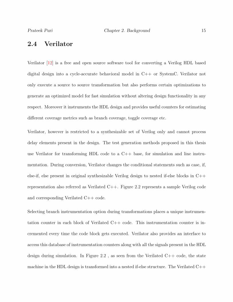
2.4 Verilator
Verilator [12] is a free and open source software tool for converting a Verilog HDL based
digital design into a cycle-accurate behavioral model in C++ or SystemC. Verilator not
only execute a source to source transformation but also performs certain optimizations to
generate an optimized model for fast simulation without altering design functionality in any
respect. Moreover it instruments the HDL design and provides useful counters for estimating
different coverage metrics such as branch coverage, toggle coverage etc.
Verilator, however is restricted to a synthesizable set of Verilog only and cannot process
delay elements present in the design. The test generation methods proposed in this thesis
use Verilator for transforming HDL code to a C++ base, for simulation and line instru-
mentation. During conversion, Verilator changes the conditional statements such as case, if,
else-if, else present in original synthesizable Verilog design to nested if-else blocks in C++
representation also referred as Verilated C++. Figure 2.2 represents a sample Verilog code
and corresponding Verilated C++ code.
Selecting branch instrumentation option during transformations places a unique instrumen-
tation counter in each block of Verilated C++ code. This instrumentation counter is in-
cremented every time the code block gets executed. Verilator also provides an interface to
access this database of instrumentation counters along with all the signals present in the HDL
design during simulation. In Figure 2.2 , as seen from the Verilated C++ code, the state
machine in the HDL design is transformed into a nested if-else structure. The Verilated C++
Prateek Puri Chapter 2. Background 16
if (vlTOPp->reset)
{
++(vlSymsp->__Vcoverage[0]); vlTOPp->v__DOT__FSM_var = 0U;
}
else
{ ++(vlSymsp->__Vcoverage[11]);
if ((0U == (IData)(vlTOPp->v__DOT__FSM_var)))
{ ++(vlSymsp->__Vcoverage[3]);
if (((IData)(vlTOPp->line1) & (IData)(vlTOPp->line2)))
{ ++(vlSymsp->__Vcoverage[1]); vlTOPp->v__DOT__FSM_var = 0U;}
else
{ ++(vlSymsp->__Vcoverage[2]); vlTOPp->v__DOT__FSM_var = 1U; }
}
else
{
if ((1U == (IData)(vlTOPp->v__DOT__FSM_var)))
{ ++(vlSymsp->__Vcoverage[6]);
if (((IData)(vlTOPp->line1) & (IData)(vlTOPp->line2)))
{ ++(vlSymsp->__Vcoverage[4]); vlTOPp->v__DOT__FSM_var = 0U;}
else
{ ++(vlSymsp->__Vcoverage[5]); vlTOPp->v__DOT__FSM_var = 2U;}
}
else
{ if ((2U == (IData)(vlTOPp->v__DOT__FSM_var)))
{ ++(vlSymsp->__Vcoverage[9]);
if (((IData)(vlTOPp->line1) & (IData)(vlTOPp->line2)))
{ ++(vlSymsp->__Vcoverage[7]); vlTOPp->v__DOT__FSM_var = 1U;}
else
{ ++(vlSymsp->__Vcoverage[8]); vlTOPp->v__DOT__FSM_var = 0U;}
}
else
{ ++(vlSymsp->__Vcoverage[10]); vlTOPp->v__DOT__FSM_var = 0U;}
}
}
}
if (reset === 1'b1)
FSM_var = a;
else
begin
case (FSM_var)
a:
begin
if ( line1 === 1'b1 & line2 === 1'b1 )
FSM_var = a;
else
FSM_var = b;
end
b:
begin
if ( line1 === 1'b1 & line2 === 1'b1 )
FSM_var = a;
else
FSM_var = c;
end
c:
begin
if ( line1 === 1'b1 & line2 === 1'b1 )
FSM_var = b;
else
FSM_var = a;
end
default:
FSM_var = a;
endcase
end
Figure 2.2: Sample Verilog code and corresponding Verilated C++ code
Prateek Puri Chapter 2. Background 17
code is instrumented and a database of counters (++(vlSymsp→_Vcoverage[xx]) related to
branch activation is provided for estimating the coverage of basic code blocks/branches. The
value of such counters is initialized to zero and is incremented every time that particular
code block is executed.
2.5 Particle Swarm Optimization
Evolutionary algorithms such as Genetic Algorithms (GA), Particle Swarm Optimization
(PSO), and Ant Colony Optimization (ACO) are nature-inspired stochastic algorithms used
to find optimal or near-optimal solutions to large scale optimization problems. Such algo-
rithms try to emulate either biological evolution and/or social interactions among species.
Since its inception in 1995 by Kennedy and Eberhart [13], PSO has attracted many re-
searchers as a global optimization technique in the continuous domain because of its sim-
plicity and ease of implementation. Similar to other nature inspired algorithms such as GA,
ACO, etc., PSO contains a population of candidate solutions which are individually known
as particles and collectively called as a swarm. PSO tries to imitate the social interactions
among the members of a swarm and uses algebraic operators to improve the particles. In
PSO, every particle is associated with a d-dimensional velocity and position vector. The
position vector represents a feasible solution whereas the velocity vector controls its motion
in the d-dimensional search space. The particles also have memory to remember their best
experiences so far during the evolution process. Also the overall best experience of the swarm

Prateek Puri Chapter 2. Background 18
is memorized and updated during evolution. Higher velocities promote exploration whereas
lower velocities result in convergence. In a given iteration, every particle in the swarm tries
to improve its position. The movement of particle in the search space is governed by its
inertia, its own previous best learning and collective experience of the swarm.
From theoretical analysis of particle's trajectory in both continuous and discrete domains,
Clerc & Kennedy [14] found that each particle converges quickly to a weighted mean of
its own best position and the global best position. The reason for fast convergence was
attributed to the one way information sharing mechanism in PSO as the global best particle
is the only agent that supplies information to all other particles. When compared to PSO, GA
and ACO are significantly different in the way of sharing information. While PSO possesses
a direct global control, ACO is based on stigmergy. In other words, each ant in ACO
examines goodness of all available paths from a node in the graph before choosing one which
in turn slows down ACO. GA when compared to PSO exhibits a mutual information sharing
process. For instance, the entire population in a GA moves relatively uniformly towards
optimal region whereas PSO is heavily influenced by the best solution. Although problem
specific, PSO typically outperforms both GA and ACO especially in terms of convergence
speed [15]. Hassan et al. in [16] validate the computational efficiency of PSO over GA using
formal hypothesis testing approach on standard benchmark functions. A detailed description
of PSO is presented in [13,14,17–19].
The performance of PSO for continuous domain problems motivated researchers to develop
modified versions to handle discrete optimization problems. In this regard, Kennedy [20]

Prateek Puri Chapter 2. Background 19
proposed the discrete binary version of PSO (BPSO) algorithm. Later, different variants of
discrete PSO were applied to solve combinatorial problems like Travelling Salesman, planar
graph coloring, resource constrained job scheduling, financial ratio selection, etc. However,
in the original version of BPSO, there were certain difficulties in the interpretation of con-
tinuous domain PSO to either the discrete or binary domain. Khanesar et al. in [21] address
such issues and present a better interpretation of discrete/binary PSO. Another important
component in the discrete PSO is the transfer function which is used for mapping the contin-
uous domain velocity component into a discrete domain component known as bit changing
or flipping probability. Traditional BPSO algorithms implemented an S-shaped transfer
functions; however, in [22] it was found that using V-shaped transfer functions on standard
benchmark functions improved performance of BPSO. The proposed test generation method
in this paper uses a variant of binary PSO [21] with a V shaped transfer function. Here,
each particle is associated with two velocities or bit flipping probabilities.
During generation (t), the following equations are used to govern the movement of particle
(i) in dimension (j ) of search space.
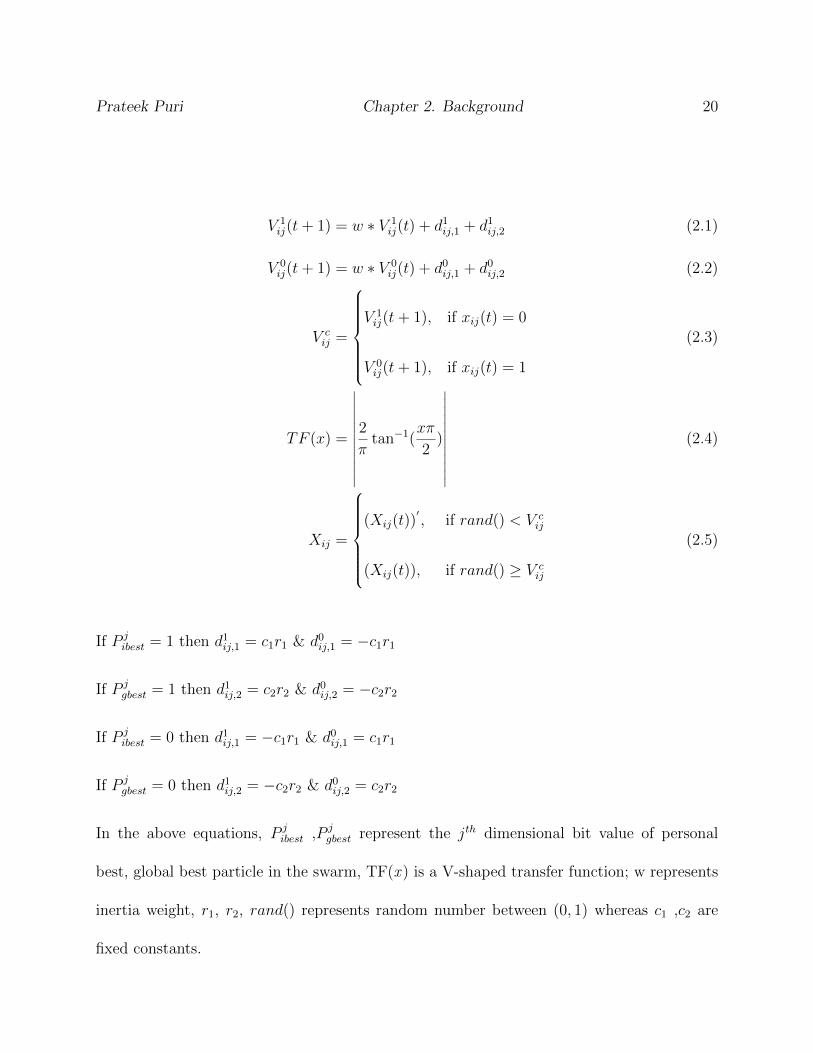
Prateek Puri Chapter 2. Background 20
V 1ij(t+ 1) = w ∗ V 1
ij(t) + d1ij,1 + d1ij,2 (2.1)
V 0ij(t+ 1) = w ∗ V 0
ij(t) + d0ij,1 + d0ij,2 (2.2)
V cij =
V 1ij(t+ 1), if xij(t) = 0
V 0ij(t+ 1), if xij(t) = 1
(2.3)
TF (x) =
∣∣∣∣∣∣∣∣∣∣∣∣2
πtan−1(
xπ
2)
∣∣∣∣∣∣∣∣∣∣∣∣(2.4)
Xij =
(Xij(t))
′, if rand() < V c
ij
(Xij(t)), if rand() ≥ V cij
(2.5)
If P jibest = 1 then d1ij,1 = c1r1 & d0ij,1 = −c1r1
If P jgbest = 1 then d1ij,2 = c2r2 & d0ij,2 = −c2r2
If P jibest = 0 then d1ij,1 = −c1r1 & d0ij,1 = c1r1
If P jgbest = 0 then d1ij,2 = −c2r2 & d0ij,2 = c2r2
In the above equations, P jibest ,P j
gbest represent the jth dimensional bit value of personal
best, global best particle in the swarm, TF(x ) is a V-shaped transfer function; w represents
inertia weight, r1, r2, rand() represents random number between (0, 1) whereas c1 ,c2 are
fixed constants.

Prateek Puri Chapter 2. Background 21
2.6 Hooke Jeeves Method
Pattern search methods belongs to the class of numerical optimization methods that do
not require the gradient of the problem to be optimized. Such methods are also known as
black box methods. Hooke Jeeves algorithm [23] belongs to the class of heuristic pattern
search methods. In comparison to the traditional gradient based methods, Hooke Jeeves
is derivative free which makes it suitable for solving non-continuous, non-differentiable and
multi-objective optimization problems. Hooke Jeeves starts with a base solution and ex-
plores the search space by using a set of exploratory and pattern search moves to improve
the associated fitness function. While an exploratory move is a crude search for some gra-
dient direction, a pattern search move refers to the larger moves in the direction of fitness
improvement. Other similar techniques [24] include Simplex method, Powell algorithm etc.
In the HJ method, for initial position vector Xk and a perturbation vector ∆ki ε Q+, the
method looks for a new position Xk1 in d-dimensional search space ωk where
ωk = {x = X|x = Xki + ∆ki, i = {1,2,...,d}} (2.6)
In case of failure of an exploratory move, the perturbation factor is reduced and the current
position is not changed. Otherwise, a pattern move is applied in the direction of better
fitness value and the current position is updated. The algorithm is terminated when the
perturbation factor becomes less than the predefined limit. Figure 2.3 shows an example of
exploratory search in Hooke Jeeves. Bigger steps in the form of pattern moves are taken in

Prateek Puri Chapter 2. Background 22
the direction of successful exploratory moves.
Base
Solution
Hooke Jeeves
exploratory search for
two variable problem
Figure 2.3: Exploratory move of Hooke Jeeves method for a problem with two variables
Figure 2.3 shows an exploratory move for an optimization problem using two unknown
variables. This move is a crude search for a gradient towards better fitness. After exploring
both x,y directions, a net direction for movement is found. Larger moves are then made in
direction leading to better fitness.
2.7 Static Analysis and Control Flow Graph
Static analysis refers to the analysis of the program without executing it. This is in con-
trast to dynamic analysis which is performed during run time. Static analysis is typically
performed on source code and sometimes on the object code. Static analysis is done to find
Prateek Puri Chapter 2. Background 23
bugs in the program or to check if the design conforms to the design guidelines.
Compilers perform static analysis to complete the above mentioned tasks. In the current
work we perform static analysis on the DUT to extract critical design information and to
extract the program structure for RTL design verification. Static analysis has been previously
used in RTL design verification problem [25], [26].
case (S2)
0:
begin
if (sd === 1'b1)
begin S2 <= 1; ... end
else
begin S2 <= 0; ... end
end
1:
begin S2 <= 2; … end
2:
begin
if (cnf === 1'b0)
begin S2 <= 2; … end
else
begin
if (mpx === 1'b0)
begin S2 <= 1; ... end
else
begin S2 <= 3; ... end
end
end
3:
begin S2 <= 0; ... end
default:
;
endcase
0
1
2
3
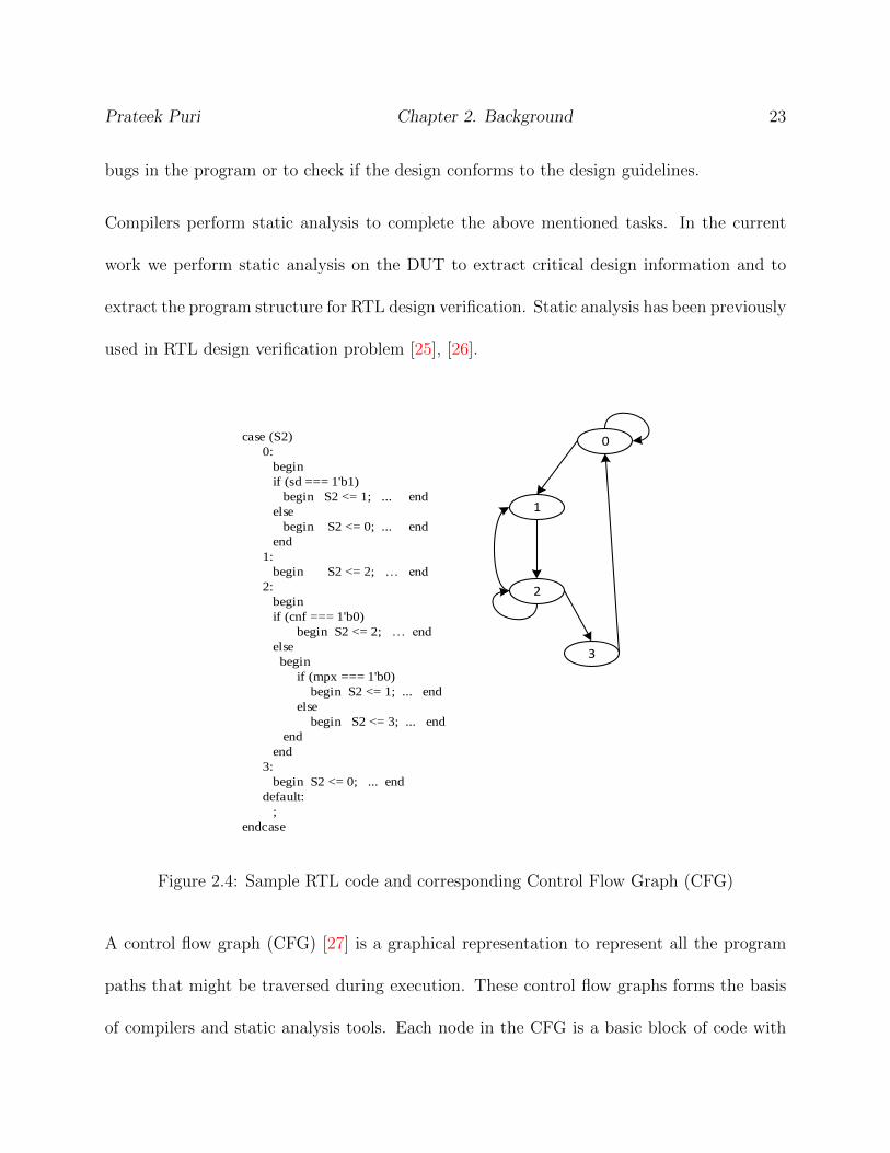
Figure 2.4: Sample RTL code and corresponding Control Flow Graph (CFG)
A control flow graph (CFG) [27] is a graphical representation to represent all the program
paths that might be traversed during execution. These control flow graphs forms the basis
of compilers and static analysis tools. Each node in the CFG is a basic block of code with

Prateek Puri Chapter 2. Background 24
only one statement leading to execution of another basic block. The jumps in the CFG are
represented by directed edges connecting the basic blocks of code. An example of a RTL
program and its corresponding CFG is shown in Figure 2.4 .
2.8 Static Single Assignment
Static Single Assignment [28] is a form of program representation where variables are assigned
exactly once in the program. New assignments to the same variable will result in the creation
of different versions of that variable. This is particularly used by compilers to modify the
program. The original program is rarely in the SSA form as same variables can be assigned
multiple times throughout the program. SSA representation modifies the program such
that every assignment to the same variable results in the creation of new version of that
variable. The versions are differentiated from each other by changing variable subscripts.
The implementation of SSA presents a clearer picture of the data flow in the program.
Different versions of the same variable are distinguished by subscripting the variable name
with its version number. Variables used in the right-hand side of expressions are renamed
so that their version number matches with that of the most recent assignment.
A = B + C + A
B = C + A
C = C + B

Prateek Puri Chapter 2. Background 25
For example, in the above code segment application of SSA will result in the modified code
segment shown below:
A 1 = B + C + A
B 1 = C + A 1
C 2 = C 1 + B 1
As observed the variables as updated when they are assigned a new value. From test gener-
ation point of view, application of SSA helps to differentiate variables across multiple time
frames and preserved the multi cycle nature of hardware design.
2.9 Satisfiability Modulo Theory (SMT)
Satisfiability is one of the fundamental problems in engineering design and refers to problem
of finding an existing solution to a constrained mathematical formula with respect to a
combination of background theories. It is applicable is many domains of engineering and
sciences particularly in software and hardware verification, scheduling, graph problems, test
generation etc. A first order mathematical formula is derived using variables, functions and
predicate symbols. The formula is then solved using SMT solvers to find a solution model (if
exists). Whereas Boolean SAT solvers work on logical formula derived from binary variables,
the more recent SMT solvers can work at higher levels of design abstraction.
SMT solvers are used to check the satisfiability of the symbolic path constraints involving

Prateek Puri Chapter 2. Background 26
integers, bitvectors, real numbers, etc [29]. To check the satisfiability of a given formula, each
clause in the formula is added to an instance of the SMT solver in the form of assertions. If
the formula is satisfiable, a model can be retrieved indicating the values of symbols/variables
used in the assertions. In the past, SMT solvers have been used for generating test vectors
for digital circuits [30,31]. Since we analyze the design at a higher level of abstraction (RTL),
SMT solver is used instead of Boolean SAT solver for the proposed methods in this thesis.
2.10 Z3 SMT Solver & Symbolic Backward Execution
Z3 [32] is state of the art SMT solver developed at Microsoft Research and is available for
free for academic research. Z3 is an efficient combination of a host of theory solvers and can
be used to check the satisfiability of logical formulas. It is currently used in solving problems
related to verification, test generation, software and hardware program analysis etc. and is
available in Python and C++ programming languages. For the current work we used the
Z3 solver available in Python. For solving the formula, different clauses in the formula are
added as assertions to Z3 solver instance and the model is retrieved if the formula is found
to be satisfiable.
In addition, all the variables involved in an assertion should be of the same form (integer,
bit vector) etc.; Z3 provides functions for converting one variable form to another variable
form. Moreover, the nature of variable assignment has to be preserved before adding it as
an assertion to the solver instance. The following gives a few examples to demonstrate the

Prateek Puri Chapter 2. Background 27
relevant cases:
Example 1: Var A = Var b
Example 2: BitVec A = BitVec b + Int c
Example 3: Var A = Var A - 2
Before adding the above examples as assertions to a solver instance, they are converted to
the following form.
Modified Example 1: Var A == Var b
Modified Example2: BitVec A == BitVec b + Int2BV(Int c)
Modified Example 3: Var A == Var A 1 - 2
Example 1 is converted from an assignment statement to a clause whereas in example 2,
variable Int c is converted to BitVector format for compatibility. In example 3, we use static
single assignment (SSA) as example 3, in its native format will be always be returned as
unsatisfiable by the SMT solver.
Symbolic execution [33] refers to execution of a single program path with symbolic input
values. Symbolic backward execution refers to the program exploration in the backward
direction starting from target. Since the graph is traversed backwards, only those paths that
can lead to the target condition are explored. SBE is performed on concrete execution paths
in the code, and the path constraints thus generated are solved using a SMT solver. Both

Prateek Puri Chapter 2. Background 28
symbolic execution and SBE are extensively used especially in RTL design validation [6,25]
and software testing [34].
2.11 Chapter Summary
The chapter covers preliminaries which will be useful to understand the methods proposed in
chapter 3 and chapter 4. Different concepts related to global optimization and satisfiability
modulo theory along with basics of functional verification, coverage metrics and digital logic
were discussed.
Chapter 3
Fast Stimuli Generation for Design
Validation of RTL Circuits Using
Binary Particle Swarm Optimization
Prateek Puri and Michael S. Hsiao
”Fast Stimuli Generation for Design Validation of RTL Circuits Using Binary Particle Swarm
Optimization,”Proceedings of IEEE Computer Society Annual Symposium on VLSI, July
2015, used with the permission of IEEE, 2015
29

Prateek Puri 3. Fast Stimuli Generation for Design Validation of RTL Circuits Using BPSO 30
3.1 Introduction
Using Hardware Descriptive Languages such as VHDL and Verilog for designing chips have
become a common practice in the industry. Designing at a higher level of abstraction such
as RTL results in comprehensible design and allows reusability of the sub modules. Despite
several benefits of designing at higher abstraction level, validating a RTL design is challeng-
ing. Design validation has been recognized as a bottleneck in the design cycle before the
final release can be made. Thus, design validation not only exacerbates the time to market
factor but also consumes many resources. Previously, several coverage metrics such as state
coverage, condition coverage, branch coverage, path coverage, etc. [3] have been proposed
and used to evaluate the quality of the test stimuli. In the ideal scenario, a high quality test
sequence should be of minimal length and offer maximum coverage as per any adopted met-
ric. Random stimuli generally fail to achieve a high coverage as some branches may require
a specific test sequence in order to be covered. Even though several advancements have been
made in coverage-directed test generation, derivation of high quality test sequences remains
an arduous task.
In recent years, several proposed techniques such as HYBRO [6] and BEACON [4] have shown
great potential in the field of test generation at the RTL. HYBRO unrolls the circuit and
then applies a Satisfiability Modulo Theory (SMT) solver to determine an input assignment
corresponding to a target path. The computational cost of SMT solvers may limit both the
length of paths and the number of branches that can be explored; thus, it may fail to cover

Prateek Puri 3. Fast Stimuli Generation for Design Validation of RTL Circuits Using BPSO 31
those branches that require long sequences of vectors. Existing simulation-based methods,
on the other hand, can scale to larger designs. For example, BEACON targets hard-to-reach
branches without resorting to deterministic engines such as symbolic execution in HYBRO.
However, simulation-based methods require effective guidance, without which the resulting
sequence can be long and may still require much execution time.
Nature-inspired population based stochastic optimization techniques such as Genetic Algo-
rithm (GA), Ant Colony Optimization (ACO), Particle Swarm Optimization (PSO), etc. are
robust and computationally efficient optimization methods for solving large scale problems
that contain several local optima. However, substantial computational effort is required in
fine tuning the search. To improve convergence rate and solution quality, such global search
methods are typically hybridized with local search techniques [35]. Local search starts by
adopting a population member as its base solution. It then explores the local neighbor-
hood around the base solution and feedbacks the additional information gained to the global
search. The hybrid global-local search algorithms are comparatively faster and generally
produce better results. With the aim of developing simple, fast and effective stimuli gener-
ation techniques for a variety of RTL designs, we propose an alternative approach: Particle
Swarm Optimization based Functional Test generator (PSOFT). PSOFT hybridizes Parti-
cle Swarm Optimization technique with a controlled graphical search method in which each
particle represents a candidate test sequence. Compared to GA and ACO, the strengths of
PSO are in its inherent simplicity and typically faster convergence rate through its one way
information sharing mechanism.

Prateek Puri 3. Fast Stimuli Generation for Design Validation of RTL Circuits Using BPSO 32
In PSOFT, the search starts from targeting easy branches to covering hard to reach branches
in later stages by altering the objective function and gradually growing the size of both the
swarm and the particles. When compared to conventional hybrid evolutionary techniques,
the controlled search feedbacks information to the swarm to improve results, but starts from
the reset state. Thus, the controlled search does not need to rely on an initial solution
vector which is required by conventional local search techniques. In addition, in order to
reduce computational effort, the controlled search is selectively activated. In comparison to
previous methods, PSOFT either matches or surpasses branch coverage for all ITC'99 [36]
benchmark circuits with significant improvements in execution time and test set sizes.
3.2 Related Work
In [37] Corno et al. introduced a suite of synthesizable RT level benchmarks and proposed
ARTIST, a Genetic Algorithm (GA) based automatic test generator. ARTIST uses GA
to analyze simulation traces in the instrumented code and then provides improved test
sequences to a VHDL simulator. ARTIST demonstrated the feasibility of RT-Level test
generator, thus improving the overall validation flow. In [38] Li et al. proposed ATCLUB
for test generation. In ATCLUB, clusters of circuit states are formed which simplifies the
finite state machine and makes test generation easier. ATCLUB reduces computation time
and vector count by slightly compromising on coverage. Both ARTIST and ATCLUB failed
to reach several hard targets.
Prateek Puri 3. Fast Stimuli Generation for Design Validation of RTL Circuits Using BPSO 33
In recent years, HYBRO [6] and BEACON [4] have been proposed as a branch coverage driven
technique for RT level test generation. HYBRO analyzes the Control Flow Graph (CFG) of
the RTL statically, extracts symbolic expressions and passes them to a SMT solver. HYBRO
performs circuit unrolling, but for branches that require long specific sequences, unrolling
over large number of cycles becomes impractical. Also, the usage of SMT solvers usually adds
high computational complexity thus increasing the computation time of overall technique.
BEACON combines the ant colony optimization (ACO) method with an evolutionary tech-
nique to improve its exploration capability. It covers hard to reach targets by removing more
visited paths from the search space thus improving upon final coverage. However, BEACON
uses a constructive meta-heuristic algorithm (ACO) where at each step ants have to look at
an entire set of paths before selecting one. Thus, a significant portion of total computational
effort is required to determine the utility of all available paths which inherently slows down
its convergence rate and may result in long test sequences. Although long test sequences can
be compacted subsequently, via test compaction techniques such [39, 40], such procedures
can still be expensive. Hence, there is a need to generate shorter test sequences to save the
additional computational effort.
Whereas HYBRO and BEACON use higher level of abstraction for design validation, pop-
ulation based stochastic techniques have been implemented to achieve gate level stuck-at
coverage [41–43]. In [44] parallel genetic algorithms were proposed to achieve significant
speed up over sequential GA for test generation. In [45] a new method for state justifica-
tion was proposed to achieve very high fault coverage using state-transfer sequences and
Prateek Puri 3. Fast Stimuli Generation for Design Validation of RTL Circuits Using BPSO 34
Genetic Algorithms. However, during test generation at the gate level, these metaheuristics
miss the chance of using information available at higher level descriptions such as branching
conditions or control paths. Recently, Gent and Hsiao in [46] proposed a mixed level test
generation technique which uses a feedback mechanism between RT level and gate level. The
technique used dominators in circuit graph to identify critical nodes which can lead away
from target node. These critical nodes were used as guiding points for test generation.
3.3 PSOFT Framework
This section presents the proposed test generation framework and heuristics used. Figure 3.1
illustrates a high level flow of the test generation process. The HDL is first cross-compiled to
C++ using Verilator [12] for faster simulation when compared to other public domain Verilog
simulators. The compiled code is also instrumented which provides a one-to-one mapping
between HDL source and C++ base; a database of counters related to branch activations
is built. These database counters are used in determination of fitness values of particles at
run time. Furthermore, Verilator provides an interface to access the internal variables and
registers of DUT. The control flow graph (CFG) of the code extracted by Verilator is later
used in the second stage for a controlled graphical search technique embedded in our binary
PSO.
Since every primary input is mapped to a separate dimension in the search space, the value of
individual element in an input test vector becomes binary in nature, hence a binary variant

Prateek Puri 3. Fast Stimuli Generation for Design Validation of RTL Circuits Using BPSO 35
of PSO is implemented. The position of every particle represents a sequence of vectors with
each vector mapped to a separate primary input and is initialized with random binary values
for n clock cycles forming a d-dimensional candidate solution. To promote exploration during
the initial stages, the d-dimensional velocity vector is randomly initialized to high values as
a logarithmic function of particle's dimension. During the first initial runs of PSOFT, the
goal is to cover as many branches as possible. Thus, the fitness of an individual particle is
directly related to the branch coverage achieved by it. Later, the focus shifts to covering
the remaining hard-to-reach branches by adjusting the objective function and allowing for
controlled explosions in the swarm population which enhances its exploration capability.
Controlled explosion of the swarm in later stages is used to target hard branches. While
adding more particles enhances the exploration capability, some branches may require longer
test sequences to be reached. Thus, the size of particles (corresponding to the sequence
length) can be dynamically increased to allow the swarm to penetrate deeper in the circuit
covering those branches. Unlike deterministic methods that can only handle on the order
of hundreds of cycles, we can allow the particles to represent tens of thousands of cycles.
Moreover, the graphical controlled search is activated whenever the swarm fails to achieve the
desired coverage despite increases in exploration and penetration capability. The controlled
search specifically targets a given branch and feedbacks the structural information gained
by it to the swarm. A set of valid and critical nodes is constructed to guide the search. It
has been empirically observed that the uncovered branches in many cases are related. Thus,
targeting a branch from the uncovered set of branches often leads to discovery of new states
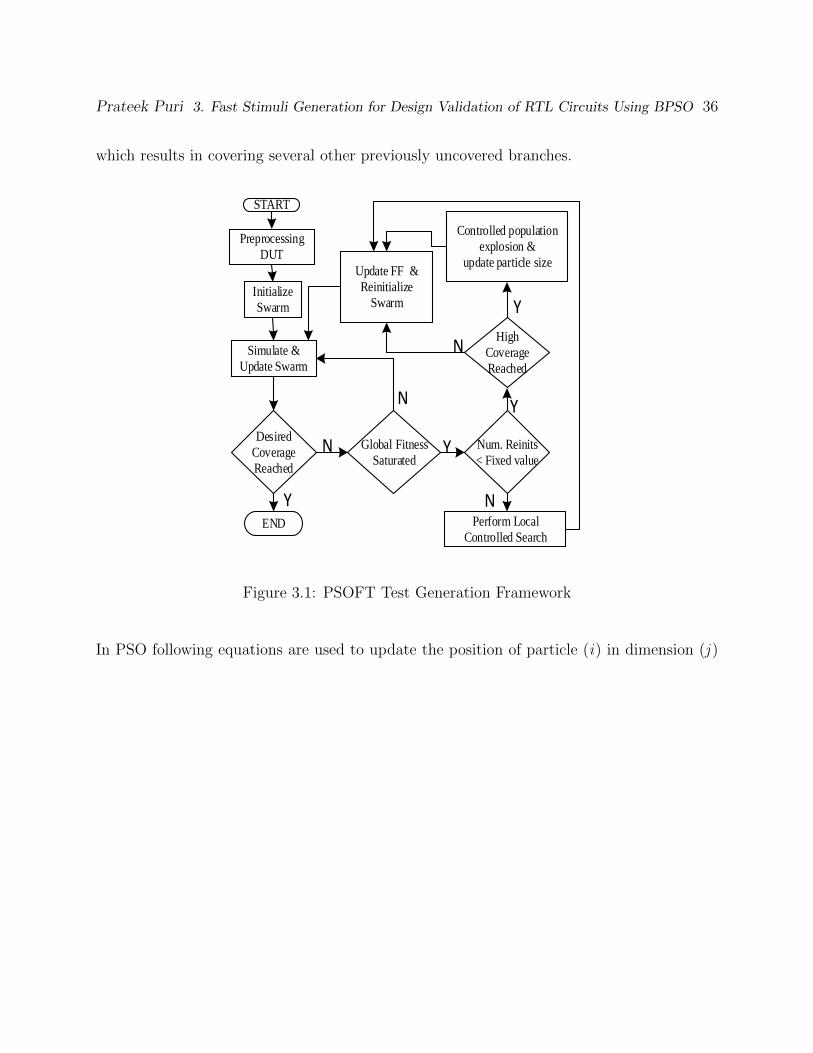
Prateek Puri 3. Fast Stimuli Generation for Design Validation of RTL Circuits Using BPSO 36
which results in covering several other previously uncovered branches.
START
Initialize
Swarm
Simulate &
Update Swarm
Desired
Coverage
Reached
Global Fitness
Saturated
Num. Reinits
< Fixed value
Perform Local
Controlled Search
High
Coverage
Reached
Update FF &
Reinitialize
Swarm
Controlled population
explosion &
update particle size
N
N
N
N
Y
Y
Y
Y
Preprocessing
DUT
END
Figure 3.1: PSOFT Test Generation Framework
In PSO following equations are used to update the position of particle (i) in dimension (j )
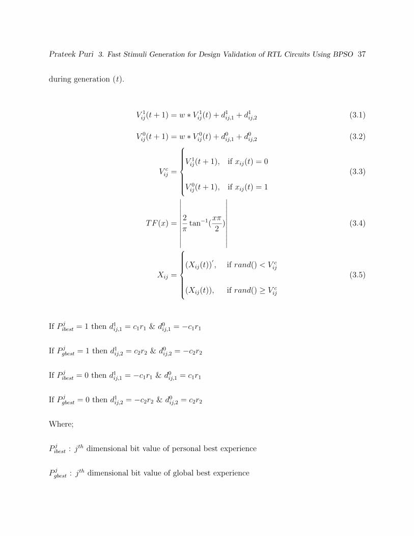
Prateek Puri 3. Fast Stimuli Generation for Design Validation of RTL Circuits Using BPSO 37
during generation (t).
V 1ij(t+ 1) = w ∗ V 1
ij(t) + d1ij,1 + d1ij,2 (3.1)
V 0ij(t+ 1) = w ∗ V 0
ij(t) + d0ij,1 + d0ij,2 (3.2)
V cij =
V 1ij(t+ 1), if xij(t) = 0
V 0ij(t+ 1), if xij(t) = 1
(3.3)
TF (x) =
∣∣∣∣∣∣∣∣∣∣∣∣2
πtan−1(
xπ
2)
∣∣∣∣∣∣∣∣∣∣∣∣(3.4)
Xij =
(Xij(t))
′, if rand() < V c
ij
(Xij(t)), if rand() ≥ V cij
(3.5)
If P jibest = 1 then d1ij,1 = c1r1 & d0ij,1 = −c1r1
If P jgbest = 1 then d1ij,2 = c2r2 & d0ij,2 = −c2r2
If P jibest = 0 then d1ij,1 = −c1r1 & d0ij,1 = c1r1
If P jgbest = 0 then d1ij,2 = −c2r2 & d0ij,2 = c2r2
Where;
P jibest : jth dimensional bit value of personal best experience
P jgbest : jth dimensional bit value of global best experience

Prateek Puri 3. Fast Stimuli Generation for Design Validation of RTL Circuits Using BPSO 38
TF (x) : V-shaped transfer function for converting continuous velocity to discrete probability
w : Inertia weight in Particle Swarm Optimization
r1, r2, rand() : Random number between (0, 1)
c1, c2 : Fixed constants used in BPSO
The presence of a central control allows the swarm to converge quickly but may sometimes
lead to a premature convergence. In such cases, it is beneficial to reinitialize the swarm
while removing the already covered branches from the target list. The updated target list
is used for fitness determination in the reinitialized swarm, thus allowing the swarm to
escape previously encountered local optima. A controlled graphical search is activated if
the algorithm runs out of fixed number of re-initializations without reaching desired branch
coverage. The information gained by this search is fed back to PSO for improved test
generation. The details of the controlled graphical search algorithm is presented in Section
3.3.2.
3.3.1 Overcoming fitness oscillation
The position vector of the global best particle is added to the final test set while dropping
the branches covered by it from the target list. In a scenario where personal best experience
of particle conflicts with global best, the net force exerted on particle can make its velocity
oscillate. To make an informed decision effect of second best particle in swarm is considered
while updating velocity of particle in that particular dimension. This is done by adding

Prateek Puri 3. Fast Stimuli Generation for Design Validation of RTL Circuits Using BPSO 39
parameters d1ij,3 and d0ij,3 to Eq.3.1 and Eq.3.2 respectively.
If P jgbest = P j
ibest then d1ij,3 = d0ij,3 = 0
else
If P j
sbest = 1 then d1ij,3 = c3r3, d0ij,3 = −c3r3
If P jsbest = 0 then d1ij,3 = −c3r3, d0ij,3 = c3r3
Where;
P jsbest : jth dimensional bit value of best experience second best particle in the swarm
r3 : Random number between (0, 1)
c3 : Fixed constant used in BPSO
Figure 3.2 represent one dimensional movement of particle due to attractive/repulsive forces
applied on it.
S G D P
F2
Fnet
F1
G D
Fnet
P
Figure 3.2: Net force on Dth dimension due to Pibest, Pgbest & Psbest
Figure 3.3 shows a d-dimensional position update for a particle in an iteration. It is highly
probable that a few branches in DUT will require longer test sequences. To handle such
cases, the particle's size is dynamically increased. The size of the swarm is also increased by
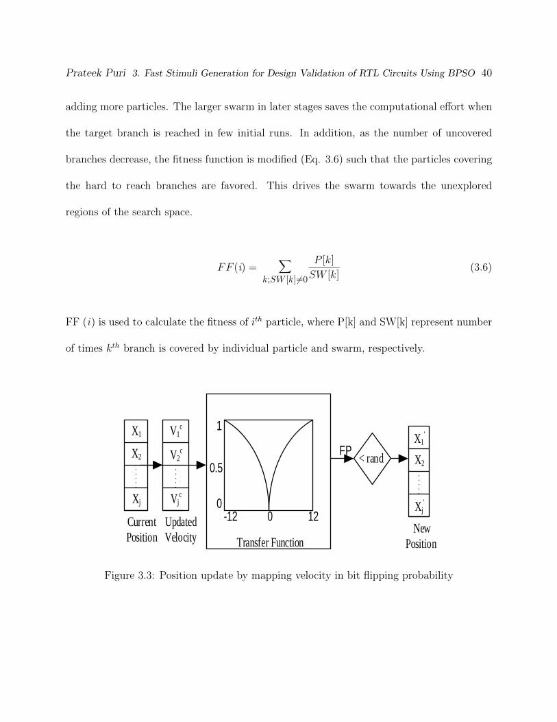
Prateek Puri 3. Fast Stimuli Generation for Design Validation of RTL Circuits Using BPSO 40
adding more particles. The larger swarm in later stages saves the computational effort when
the target branch is reached in few initial runs. In addition, as the number of uncovered
branches decrease, the fitness function is modified (Eq. 3.6) such that the particles covering
the hard to reach branches are favored. This drives the swarm towards the unexplored
regions of the search space.
FF (i) =∑
k;SW [k]6=0
P [k]
SW [k](3.6)
FF (i) is used to calculate the fitness of ith particle, where P[k] and SW[k] represent number
of times kth branch is covered by individual particle and swarm, respectively.
V1c
Vjc
V2c
Current
Position New
PositionTransfer Function
Updated
Velocity
< rand
X1
X2
Xj
X1'
X2
Xj'0
0.5
1
-12 0 12
FP
Figure 3.3: Position update by mapping velocity in bit flipping probability

Prateek Puri 3. Fast Stimuli Generation for Design Validation of RTL Circuits Using BPSO 41
3.3.2 Controlled Graphical Search Method
The graphical search is selectively activated as some branches may require very long and/or
specific sequence of input vectors. Many of such uncovered branches are inter-related, and
reaching any one of them can often lead to the discovery of several previously uncovered
branches. The detail of the search is illustrated in Figure 3.4. The controlled search starts
with a target node, a set of valid nodes and a fitness function for progress evaluation. The
valid node set (VNS) represents those nodes which can lead to target node obtained from
the CFG. Beginning from the start node, all the outgoing links are analyzed by expanding
the child nodes in a depth-first fashion until either the target node or a leaf node is reached.
Nodes leading to the target node are added to VNS. All parent nodes with at least one
child present in VNS are immediately added to VNS. The branching condition leading to
the target node serves as the fitness function for the search. The search terminates if no
improvement is seen in the fitness value for a period of time. The graphical search is very
effective especially in presence of complex looping structures in DUT.
The aim of the graphical search is to identify the critical nodes among the valid nodes. A
critical node is the one which can lead the execution to a non-valid node during the current
clock cycle. While the current implementation will only mark a node as critical if they
lead to a non-valid node, the dominators based search in [46] will mark a valid node as a
critical node if it can lead to either a non-valid node or a valid ancestral node, in case of
loops. Hence, our approach does not require the critical node to be a dominator node. To
reduce memory requirements, the control state of the circuit at a critical node is explored

Prateek Puri 3. Fast Stimuli Generation for Design Validation of RTL Circuits Using BPSO 42
START
Current
Node
critical
Retrieve i/p
vector from
database
Generate
i/p vector
Simulate vector
Target
Reach
Current node in
valid node set
Mark previous
node as critical
and backtrack
Generate vectors at
critical node till next
node is valid
Explore & compress
control state of DUT
at critical nodeSave
critical
knowledge
in database
N
NN
Y
Y
EXIT
Figure 3.4: Controlled Graphical Search
by eliminating control registers that do not affect the branching condition. It is feasible that
multiple input vectors may lead to the same valid node from a critical node. In such a case,
bit relaxation at input side is done. For example, vectors 111 and 110 can be merged to
form 11x. The information obtained at critical nodes is stored in a database and is retrieved
if the same circuit state is encountered in future. This can help generating the correct test
vector at critical nodes.
To illustrate the process of the controlled graphical search, consider the b12 circuit which is
a control intensive benchmark. B12 represents a Simon-says game in which the player has
to guess a randomly generated sequence of numbers. A right guess will lead the player to
node 63 (Figure 3.5) whereas a wrong guess will result in loss condition and termination of
the game. To reach node 68 which represents the WIN state, the player has to correctly
guess the number more than 500 consecutive times. Such stringent constraints demand a

Prateek Puri 3. Fast Stimuli Generation for Design Validation of RTL Circuits Using BPSO 43
very long and specific sequence of vectors, making it very difficult for stochastic methods to
reach the WIN state. A subsection of CFG for b12 is shown in Figure 5 where each node
represents a basic code block and edges represent the branching condition. To save space,
we omit instrumented C++ code for b12 & only show a subsection of its CFG.
In this example, we target node 68 by guiding the generation of vectors using valid and
critical nodes and use the corresponding branch condition in computing the fitness. As
evident from the CFG, the presence of several looping structures involving critical nodes
makes it very difficult to reach the WIN state. Nodes L1, L2, L3, L4, L5 represent losing
states and therefore help in determination of critical nodes: 50, 58, 59, 60 & 62. The test
generation process is guided by these determined valid and critical node sets. Proceeding
from start node inputs vectors are generated and simulated while keeping track of the current
and the last visited node. The node is marked critical if it can lead to a non-valid node (47,
49, 52, 54 & 56) during the search. The search backtracks and attempts to generate a useful
input vector whenever the search does not advance towards a valid node from a critical
node. The circuit state and useful input vector at critical nodes are saved in the database
and retrieved during future encounters which saves test generation effort, especially in case
of looping structures. It is seen that covering node 68 require a sequence of having more
than 32, 000 vectors & helped discover several previously uncovered nodes: 97, 98, 99, 100,
101 & 102.
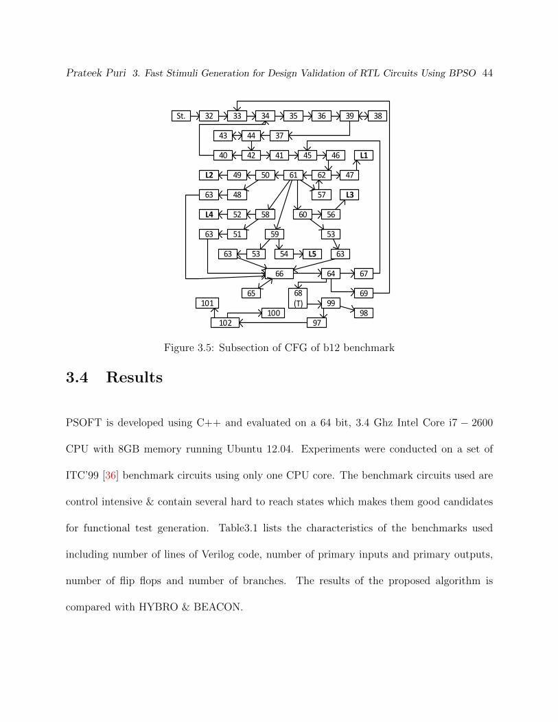
Prateek Puri 3. Fast Stimuli Generation for Design Validation of RTL Circuits Using BPSO 44
32St. 33 34 35 36 39 38
374443
4240 41 45 46
62L2 4761
L1
48
50
57
49
59
58
63
6052
L3
53
56
63
L4
53
5163
63 L554
65
66
9968(T)
97
64
98
67
69
102
101100
Figure 3.5: Subsection of CFG of b12 benchmark
3.4 Results
PSOFT is developed using C++ and evaluated on a 64 bit, 3.4 Ghz Intel Core i7 − 2600
CPU with 8GB memory running Ubuntu 12.04. Experiments were conducted on a set of
ITC’99 [36] benchmark circuits using only one CPU core. The benchmark circuits used are
control intensive & contain several hard to reach states which makes them good candidates
for functional test generation. Table3.1 lists the characteristics of the benchmarks used
including number of lines of Verilog code, number of primary inputs and primary outputs,
number of flip flops and number of branches. The results of the proposed algorithm is
compared with HYBRO & BEACON.

Prateek Puri 3. Fast Stimuli Generation for Design Validation of RTL Circuits Using BPSO 45
Table 3.1: Benchmark Characteristics
Bench #Line #Branch #PI #PO #FF
b01 110 26 2 2 5b06 128 24 2 6 9b07 92 19 1 1 49b10 167 32 11 6 17b11 118 32 7 6 31b12 105 105 5 6 121b13 379 63 10 10 53b14 509 211 32 54 245
3.4.1 Algorithmic Settings
PSOFT based approach uses the following parameters: Initial swarm size is set to 20 with an
increment of 5 particles during controlled population explosion. The number of generations
for a particular initialization of swarm is typically set to 20 whereas the swarm reinitializes
if no fitness improvement is seen for 6 consecutive generations. The size of particles is
determined by circuits size and is set to a maximum of 3000 cycles whereas the dynamic
expansion rate is set to 30% of current size. The maximum number of swarm re-initializations
is set to 10. The size of the swarm and individual particles are expanded if swarm ends with
zero fitness for 2 consecutive re-initializations.
3.4.2 Results
Table 3.2 compares the proposed approach with BEACON and HYBRO. For each circuit,
the branch coverage, execution time, & test length are reported. For PSOFT, we also
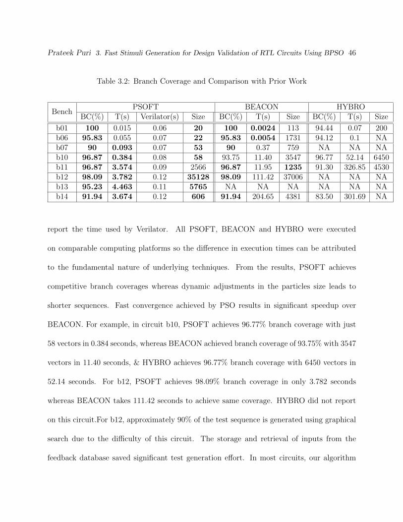
Prateek Puri 3. Fast Stimuli Generation for Design Validation of RTL Circuits Using BPSO 46
Table 3.2: Branch Coverage and Comparison with Prior Work
BenchPSOFT BEACON HYBRO
BC(%) T(s) Verilator(s) Size BC(%) T(s) Size BC(%) T(s) Size
b01 100 0.015 0.06 20 100 0.0024 113 94.44 0.07 200b06 95.83 0.055 0.07 22 95.83 0.0054 1731 94.12 0.1 NAb07 90 0.093 0.07 53 90 0.37 759 NA NA NAb10 96.87 0.384 0.08 58 93.75 11.40 3547 96.77 52.14 6450b11 96.87 3.574 0.09 2566 96.87 11.95 1235 91.30 326.85 4530b12 98.09 3.782 0.12 35128 98.09 111.42 37006 NA NA NAb13 95.23 4.463 0.11 5765 NA NA NA NA NA NAb14 91.94 3.674 0.12 606 91.94 204.65 4381 83.50 301.69 NA
report the time used by Verilator. All PSOFT, BEACON and HYBRO were executed
on comparable computing platforms so the difference in execution times can be attributed
to the fundamental nature of underlying techniques. From the results, PSOFT achieves
competitive branch coverages whereas dynamic adjustments in the particles size leads to
shorter sequences. Fast convergence achieved by PSO results in significant speedup over
BEACON. For example, in circuit b10, PSOFT achieves 96.77% branch coverage with just
58 vectors in 0.384 seconds, whereas BEACON achieved branch coverage of 93.75% with 3547
vectors in 11.40 seconds, & HYBRO achieves 96.77% branch coverage with 6450 vectors in
52.14 seconds. For b12, PSOFT achieves 98.09% branch coverage in only 3.782 seconds
whereas BEACON takes 111.42 seconds to achieve same coverage. HYBRO did not report
on this circuit.For b12, approximately 90% of the test sequence is generated using graphical
search due to the difficulty of this circuit. The storage and retrieval of inputs from the
feedback database saved significant test generation effort. In most circuits, our algorithm

Prateek Puri 3. Fast Stimuli Generation for Design Validation of RTL Circuits Using BPSO 47
matches or surpasses branch coverage achieved by existing methods with orders of magnitude
improvement in run time and test set size.
3.5 Chapter Summary
This chapter focusses upon fast & effective stimuli generation for synthesizable RTL designs
using Binary Particle Swarm Optimization (BPSO). Initially, a global search is conducted
using BPSO which is later supported by a controlled graphical search method to reach target
corner cases. The controlled search uses the CFG to provide hints at critical points in the
state space to reach hard corner cases. The fast convergence of BPSO allows PSOFT to
deliver high coverage while generating short test sequences. Substantial speedups over the
state of the art methods have also been achieved for several ITC'99 benchmark circuits.

Chapter 4
SI-SMART: Functional Test
Generation for RTL Circuits Using
Loop Abstraction and Learning
Recurrence Relationships
Prateek Puri and Michael S. Hsiao
”SI-SMART: Functional Test Generation for RTL Circuits Using Loop Abstraction and
Learning Recurrence Relationships,” ICCD 2015 (in review)
48

Functional Test Generation for RTL Circuits Using Loop Abstraction & Learning Recurrence Relationships 49
4.1 Introduction
Today, design validation is considered as one of the most time and resource consuming aspects
of hardware design. The costs associated with late detection of bugs can be enormously
high. Previously, several design coverage metrics such as line coverage, branch coverage,
state coverage, etc [3] were proposed and used to evaluate the quality of the input sequences
used for design validation. Random generation of such input sequences fail to achieve high
design coverage as certain random resistant portions of the design are left uncovered. For
achieving higher design coverage, these random input sequences are combined with manually
generated directed test sequences. Manual test generation is not only time and resource
consuming but also error prone. Together with stringent time to market factors, generating
test sequences automatically that maximize design coverage still remains one of toughest
challenges in design validation.
Design validation methodologies proposed in the last decade typically use higher levels of
design abstractions such as the Register Transfer Level (RTL). Working at higher abstraction
levels gives access to information critical for effective stimuli generation. Design validation
techniques can be broadly classified into simulation and deterministic/formal methods. In-
dustrial practices employ simulation based methods because of their scalability with design
size and ease of use. However, simulation based methods might perform poorly when a
specific sequence is needed to activate a target branch. On the other hand, formal methods
offer completeness but cannot scale to larger designs. To offset these disadvantages, several

Functional Test Generation for RTL Circuits Using Loop Abstraction & Learning Recurrence Relationships 50
semi-formal methods [8, 9] , [47] have been proposed in the past. Although semi-formal
methods combine the merits of both simulation and deterministic approaches, they still face
challenges when specific branching decisions depend on inputs supplied from hundreds or
thousands of cycles ago. In such situations, existing semi-formal methods based on Bounded
Model Checking (BMC) or symbolic execution will need to analyze and/or unroll the circuit
for thousands of cycles before determining the needed input values to reach them. Although
possible in theory, such approaches are practically infeasible due to the large computational
costs involved.
Evolutionary algorithms such as Genetic Algorithms (GA), Particle Swarm Optimization
(PSO), and Ant Colony Optimization (ACO) are nature-inspired stochastic algorithms used
to find optimal or near-optimal solutions to large scale optimization problems. Such algo-
rithms try to emulate either biological evolution and/or social interactions among agents.
Although these techniques have shown some success, their convergence rate can be slow, es-
pecially near the optimal point because of the stochastic behavior of the parameters involved.
To accelerate convergence rate of these heuristics, they are often combined with the local
search methods [48, 49]. The combination not only improves the convergence rate but also
decreases the probability of getting stuck in local optima. In several previous works [50–52]
such evolutionary techniques were effectively used for test generation.
What makes validation of today's designs difficult is the presence of complex loops in the
DUT. For example, encryption, hashing, and other state-machines that rely on input values
from many cycles in the past would make the validation process challenging. The presence of

Functional Test Generation for RTL Circuits Using Loop Abstraction & Learning Recurrence Relationships 51
loops in the DUT limits deterministic methods whereas simulation based methods are limited
by large input spaces. In this paper, we propose SI-SMART to tackle these challenges. SI-
SMART couples BPSO with an SMT-based symbolic engine to maximize branch coverage
of the RTL design. Not only does SI-SMART combine the scalability of simulation and
completeness of a formal method, it also eradicates the need of costly circuit analysis or
explicit unrolling for many cycles by intelligently extracting useful information from the
DUT. Information such as relations among variables and loops can be extremely valuable.
SI-SMART thus provides a very effective guidance when the branching decisions directly or
indirectly depend upon specific input values supplied many cycles earlier. In this regard, the
feedback between the stochastic and deterministic engines in SI-SMART offers much more
than merely the sum of individual methods.
4.2 Background
Several influential works based on abstraction-guided test generation have been proposed in
the past. In [8] Shyam and Bertacco, built abstract models by using the modules that are
closely related to the target condition. Abstract distances were used to guide simulation
but the usage of random number generators along with the abstraction bias might force the
method to get stuck in the local optimum points. In [9] and [47], efforts were made to refine
the abstracted model, but each refinement added more complexity to the problem. Typically,
a combination of random generator with some guidance is employed on the abstracted models

Functional Test Generation for RTL Circuits Using Loop Abstraction & Learning Recurrence Relationships 52
to generate test sequences.
In [50–53], random sequence generators are replaced by more sophisticated techniques such as
GA, Cultural Algorithms (CA) and ACO. Such substitution improves performance; however,
they may still get stuck in dead-end states. Moreover, methods in [50–53], utilize gate-level
netlists for determining the abstract models. Working at lower level representations of the
design makes it very difficult to mine complex relationships among circuit signals.
Liu and Vasudevan in [6] proposed HYBRO for functional test generation at RT level. HY-
BRO combines dynamic and static analysis of the RTL source code to generate validation
vectors. HYBRO performs concrete simulation and passes the mutated guard in the execu-
tion trace to a SMT solver to generate new vectors. Although HYBRO can examine every
path in theory, it can lead to path explosion which ultimately limits the number of unrolling
cycles that can be considered. Consequently, branches that require long vector sequences
are not reached. Recently in [5], Liu and Vasudevan proposed Enhanced Star method which
builds on an explored symbolic state caching technique to handle path explosion problem.
Enhanced Star achieves better coverage and is also computationally efficient when compared
to HYBRO. To handle scalability issues in HYBRO, Li et al. [4] presented BEACON which
is an ACO-based method combined with an evolutionary technique. BEACON unlike HY-
BRO does not resort to deterministic engines and can scale to larger designs. However, for
circuits that have a larger input space, test generation techniques like BEACON might have
difficulty generating the needed vectors.
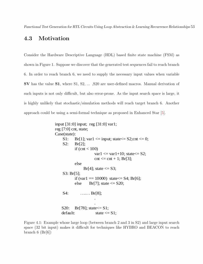
Functional Test Generation for RTL Circuits Using Loop Abstraction & Learning Recurrence Relationships 53
4.3 Motivation
Consider the Hardware Descriptive Language (HDL) based finite state machine (FSM) as
shown in Figure 1. Suppose we discover that the generated test sequences fail to reach branch
6. In order to reach branch 6, we need to supply the necessary input values when variable
SV has the value S1, where S1, S2, ... ,S20 are user-defined macros. Manual derivation of
such inputs is not only difficult, but also error-prone. As the input search space is large, it
is highly unlikely that stochastic/simulation methods will reach target branch 6. Another
approach could be using a semi-formal technique as proposed in Enhanced Star [5].
input [31:0] input; reg [31:0] var1;
reg [7:0] cnt, state;
Case(state):
S1: Br[1]; var1 <= input; state<= S2;cnt <= 0;
S2: Br[2];
if (cnt < 100)
var1 <= var1+10; state<= S2;
cnt <= cnt + 1; Br[3];
else
Br[4]; state <= S3;
S3: Br[5];
if (var1 == 10000) state<= S4; Br[6];
else Br[7]; state <= S20;
S4: ….… Br[8];
.
.
S20: Br[78]; state<= S1;
default: state <= S1;
Figure 4.1: Example whose large loop (between branch 2 and 3 in S2) and large input searchspace (32 bit input) makes it difficult for techniques like HYBRO and BEACON to reachbranch 6 (Br[6])
Functional Test Generation for RTL Circuits Using Loop Abstraction & Learning Recurrence Relationships 54
However, in order to derive the correct inputs, Enhanced Star has to unroll the above circuit
for hundreds of cycles which is often impractical due to the high computational cost of SMT
solvers. SI-SMART tries to cover target branch 6 without performing any loop unrolling
while dealing with the large input search space.
SI-SMART involves stochastic and deterministic phases with feedback between them for test
generation. While we rely on BPSO to maximize coverage, the objective of the formal phase
of SI-SMART changes to that of the Symbolic Backward Execution (SBE). This allows us
to better target specific regions of the DUT's state space. In the above example, instead of
analyzing the circuit for 100 cycles, we use an SMT solver to directly solve the circuit for the
100th cycle using SBE. The initial state for the time-frame is unconstrained. For example,
for the target branch 6 in Figure4.1, the path condition is iteratively constructed as:
var1 == 10000 ⇒ var1 == 10000 Λ cnt == 100 ⇒ var1 == 10000 Λ cnt == 100
Λ var1 == input
During backward CFG traversal, the SMT solver is repeatedly called to check the feasibility
of the path while adding new constraints. Backtracking is implemented to select a different
route if the selected path becomes unsatisfiable at any stage of the graph traversal. Im-
plementation of SSA and coupling the branch instrumentation points to values of the state
variables ensures that the multi-cycle nature of the CFG is preserved during graph traversal.
The values of real DUT inputs along with the state variables are captured while solving the
constraints. In the above case the final information retrieved from the solver will be:
Functional Test Generation for RTL Circuits Using Loop Abstraction & Learning Recurrence Relationships 55
SV: S1; input = 10000
Consequently supplying an input equal to 10000 when SV becomes equal to S1 helps in
reaching the target branch 6. However, it is observed that critical information can be lost due
to the loop abstraction (Figure1). This loss in information generates false input values which
will not allow BPSO to reach the targeted branch in the first iteration itself. Counteraction
in the form of swarm effect on selective cycles/vectors (in this case when SV equals S1)
in the sequence along with the pattern search method (Hooke Jeeves) is taken against such
information loss in SI-SMART. We will further explain this concept in the following sections.
4.4 Test Generation Framework
The high level description of SI-SMART is as follows: Initially, the RTL design is cross com-
piled to a C++ code using Verilator [12] for faster simulation when compared to other public
domain Verilog simulators. Verilator also instruments the DUT, thus building a database of
counters corresponding to various branch activations. After cross compilation, the behav-
ioral representation of the DUT provided in the HDL undergoes an automatic preprocessing
stage. During this preprocessing stage, the HDL source code is also instrumented such that
the branch instrumentation points are in-line with the Verilated C++ code. The instru-
mented HDL code is then statically analyzed to extract the corresponding CFG. Simple
loops in the design along with branching structures are also statically extracted. Both RTL
cross-compilation and preprocessing step incur a one-time cost. Next, a few runs of BPSO
Functional Test Generation for RTL Circuits Using Loop Abstraction & Learning Recurrence Relationships 56
are conducted with the aim of maximizing the branch coverage. In this phase, adjustment
of the fitness function is made to drive the swarm from the frequently visited regions to the
unexplored regions of the search space. Since BPSO works on the input space, there might
be a few hard to reach branches left uncovered. These branches are then analyzed individ-
ually by a SMT solver whose initial time frame is unconstrained. The specified branches
are targeted one by one with the goal of automatically finding the correct test inputs as
well as the corresponding cycle in which those inputs should be supplied. To generate the
needed values, the formal tool traverses the extracted CFG backwards starting from the
target branch, while performing a static single assignment (SSA) to differentiate variables
across different time frames. The code segments in various branches that do not affect the
target conditions are dynamically trimmed off during graph traversal. The target branch is
declared functionally unreachable if all the paths leading to the target branch are found to
be unsatisfiable by the SMT solver. If any path is satisfiable, the critical inputs captured are
then supplied to BPSO. The swarm action is now applied only to selective cycles as identified
by the formal tool while attempting to reach the target. To accelerate the convergence speed
of BPSO near the global optimum point, BPSO is now coupled with a pattern search method
(Hooke Jeeves) which acts as a local search method. The application of BPSO along with
the Hooke Jeeves method encounters the information loss, if any, due to loop abstraction
as the variables governing the target condition might be influenced inside the abstracted
loop. For example: in Figure1 the register variable var1 used in the branching condition for
branch 6 is updated inside the loop formed between branch 2 and 3. However during graph

Functional Test Generation for RTL Circuits Using Loop Abstraction & Learning Recurrence Relationships 57
traversal (Figure 2), SI-SMART does not analyze or unroll the loop which results in loss of
information regarding the variable modification.
Consequently the information regarding the variable modification is not captured during
the formal phase. This information loss is later compensated by the combination of BPSO
and HJ. The combination has a faster convergence rate and better search space exploitation
capability when compared to BPSO. Algorithm 1 shows the pseudo-code of SI-SMART. We
discuss different phases of SI-SMART in following sections:
4.4.1 Instrumenting HDL code and Static Analysis
In the first stage of SI-SMART, we statically extract certain semantics from the DUT. The
HDL code is instrumented such that the location of instrumentation counters have a one-to-
one mapping with that of the Verilated C++ code. These counters establish communication
between the BPSO and the SBE engine. At the same time, the control flow graph of the HDL
code is also extracted. Each node of the CFG corresponds to the basic code block executed in
the branch whereas conditions to reach the branch are represented by the edges. Also other
information such as the name, type (integer, bitvector etc), width, and functionality (regular
variable/FSM control variable) for different signals present in the DUT are extracted. This
information will be helpful to generate the path constraints during graph traversal. It is
noted that the different instrumentation points enveloped inside the same value of the FSM
variable correspond to the same cycle (Figure 4.2). This information is used while applying

Functional Test Generation for RTL Circuits Using Loop Abstraction & Learning Recurrence Relationships 58
Algorithm 1 SI-SMART
1: Instrument HDL code & perform static analysis2: Mark structurally unreachable branches as covered3: Initialize binary particle swarm4: for all swarm reinits re = 1 to Re do5: for all generations g = 1 to G do6: for all particles p = 1 to P do7: Simulate & update particle's position and velocity.8: Update Pbest, Gbest & Sbest
9: end for10: end for11: if enre = 1 then Reinitialize Swarm & goto 512: end if13: end for14: for all uncovered branches b = 1 to B do15: Traverse CFG, perform SBE and SSA16: if path unfeasible then Backtrack17: else if All Path Unfeasible then18: Mark branch unreachable, goto 1519: else20: Extract Fitness Function (FF) from the target branch & feedback BPSO21: end if22: Reinitilaize BPSO with new information & do 6-823: if target uncovered but fitness improved then24: Increase Particle Size & do 6-825: else if target uncovered & fitness not improved then26: for all generations g = 1 to G do27: Perform 6-8, set Gbest as the start point for HJ28: Perform local search using HJ29: if target covered then30: Mark all new branches found as covered31: end if32: end for
33: else34: For new target, extract FF from target branch & feedback BPSO35: end if36: end for

Functional Test Generation for RTL Circuits Using Loop Abstraction & Learning Recurrence Relationships 59
SSA on different variables during the CFG traversal. Figure 4.2 shows the extracted CFG
and node information for each branch for the example given in Figure 4.1.
As seen from the CFG in Figure 4.2; branch 79 does not have any incoming edges. Hence this
branch is declared as a structurally unreachable branch. Such branches typically correspond
to the default statements which are deliberately added to FSMs in the HDL code to prevent
the synthesis tools from inferring sequential logic and to protect the design behavior from
soft errors. After static analysis, SI-SMART proceeds to the test generation phase using
BPSO.
b1b1
b1b2
b1b3b1b4
b1b5
b1b7b1b6
b1b8
b1b78b1b_yb1b_x
b1b79
b1b2
b1b3 b1b4
S2
Br. 1 Code: var1 == ip1;
SV == S2; cnt == 0
Condition: SV == S1
Br. 2 Code: None
Condition: SV == S2
Br. 3 Code: var1 == var1+10; SV == S2; cnt == cnt+1
Condition: SV == S2 & cnt < 100
Br. 4 Code: SV == S3
Condition: SV == S2 & Not(cnt < 100)
Br. 5 Code: None
Condition: SV == S3
Br. 6 Code: SV == S4
Condition: SV == S3 &
var1 == 10000
Br. 7 Code: SV == S20
Condition: SV == S3 &
Not (var1 == 10000)
Figure 4.2: CFG and node information for the example shown in Fig.4.1

Functional Test Generation for RTL Circuits Using Loop Abstraction & Learning Recurrence Relationships 60
4.5 Test Generation using BPSO
To generate test stimuli using BPSO, each primary input present in the DUT is mapped to
an individual dimension in the search space. The position vector of the particle is randomly
initialized for N clock cycles resulting in a d-dimensional candidate solution of N vectors. The
d-dimensional velocity vector is also randomly initialized to high values using a logarithmic
function of the particle's dimension. High velocities promote exploration of the search space
which is desired in earlier stages of swarm evolution. During the first few runs of the swarm,
the goal is to cover as many branches as possible. Particle's fitness in these runs is directly
proportional to the branch coverage achieved by it. However in later runs of BPSO, the focus
shifts to cover the hard to reach states. Using a modified fitness function in latter stages
allows the swarm to drive away from the frequently explored to less traveled regions of the
search space. Particles that reach the least frequently visited regions get more weightage
(Eq. 4.1).
FF (i) =∑
k;SW [k]6=0
P [k]
SW [k](4.1)
FF (i) is used to calculate the fitness of ith particle, where P[k] and SW[k] represent number
of times kth branch is covered by individual particle and swarm, respectively. Certain hard
to reach branches might necessitate longer input sequences. To reach such hard to reach
branches, dynamic adjustments in the size of both the swarm and the particle is done. Such
adjustments enhance search space exploration capability and allow deeper penetration in the

Functional Test Generation for RTL Circuits Using Loop Abstraction & Learning Recurrence Relationships 61
circuit. Also dynamically increasing the swarm size and the particle size can help reduce
overall computational complexity as the desired branch coverage might be attained in earlier
stages of BPSO.
The simulation-based nature of BPSO allows it to be scalable to larger designs as the individ-
ual particles can represent test sequences for tens of thousands of cycles. The fitness/quality
of the particle depends upon the branch coverage it acquires. For determining fitness of
individual particles, branch instrumentation counter database present in the Verilated C++
code is utilized.
The position and velocities of the particles are updated using Eq. 1− 5 (Section 2.5 ). It is
noted that each dimension in the particle's position is binary in nature, therefore Eq. 1 and
Eq. 2 can have an oscillating effect on the particle's velocity in situations where the personal
best experience of the particle conflicts with the global best experience of the swarm. In such
situations, the personal experience of the second best particle in the swarm is considered
while updating velocity of the particle in that particular dimension. This is done by adding
parameters d1ij,3 and d0ij,3 to Eq.1 and Eq.2 (Section 2.5 ) respectively.
If P jgbest = P j
ibest then d1ij,3 = d0ij,3 = 0
else
If P j
sbest = 1 then d1ij,3 = c3r3, d0ij,3 = −c3r3
If P jsbest = 0 then d1ij,3 = −c3r3, d0ij,3 = c3r3

Functional Test Generation for RTL Circuits Using Loop Abstraction & Learning Recurrence Relationships 62
In the above equation, P jsbestrepresent the jth dimensional bit value of second best particle
in the swarm; r3 represents random number between (0, 1) whereas c3 is a fixed constant.
As noticed from Eq. 1 and Eq. 2, the global best particle has a direct effect on all the
individual particles. This presence of a central control (Gbest) and the one way information
sharing mechanism allows BPSO to achieve a high convergence rate. But this may also result
in a premature convergence, forcing the swarm to get trapped in a local optimal point. In
such situations, the swarm is reinitialized while removing the branches covered by global best
particle from the target list. SI-SMART proceeds to the formal phase of the algorithm, if
BPSO runs out of the fixed number of re-initializations without achieving the desired branch
coverage.
4.5.1 Symbolic Backward Execution using Z3
In the formal phase of SI-SMART, the SBE engine walks over the CFG extracted by the
static analysis in the first phase of SI-SMART. The path constraint for the SMT solver is
iteratively formed by performing a logical conjugation of code present inside the node and the
incoming edge. An incident node with the smallest branch id is selected first, in case multiple
nodes are incident on the current node. For example, if nodes 5 and 6 are inputs to node
7, then we will first select node 5 during graph traversal. Backtracking is also implemented
to explore other incident nodes, in case path unsatisfiability is reported by the SMT solver.
For example: Node 6 will be searched if SMT solver reports unsatisfiability after searching

Functional Test Generation for RTL Circuits Using Loop Abstraction & Learning Recurrence Relationships 63
node 5. The target branch is declared to be functionally unreachable if unsatisfiability is
reported by the SMT solver for all the physical paths leading to the target branch in the
CFG. In addition, the state variables are not used in generation of the path constraint as
their values can be determined by the instrumentation counters (Figure 4.2). The concept
of backtracking and functional unreachability is further explained by using a subsection of
the ITC'99 b11 benchmark circuit with branch 20 (st:6) as the target branch as shown in
Figure4.3.
case (st)
0: br_1 = br_1+1; cont<=1'b0;
r_in <= x_in; x_out <= 1'b0;st <= 1;
1: br_4 <= br_4+1 ; r_in <= x_in;
if (stbi) br_2 = br_2+1; st <= 1;
else st <= 2;br_3=br_3+1;
2: br_10 <= br_10+1;
if (r_in == 0 || r_in == 63)
br_7= br_7+1; cont1 <= r_in; st <= 8;
if (cont<25) br_5=br_5+1 ; cont<=cont+1;
else cont <= 1'b0; br_6= br_6+1 ;
else if (r_in <= 26) br_8= br_8+1; st <= 3;
else st <= 1; br_9= br_9+1;
3: br_13<= br_13+1 ; st <= 4;
if (r_in%2 == 1)
br_11= br_11+1; cont1 <= cont*2;
else cont1 <= cont; br_12= br_12+1;
4: br_16<= br_16+1;
if ( ((r_in % 4) / 2) == 1)
br_14= br_14+1; cont1 <= r_in+cont1; st<=5;
else cont1<= r_in-cont1; br_15= br_15+1;st <= 6;
6: br_22<= br_22+1;
if (cont1>63) br_20<=br_20+1;
b1b1
b1b4
b1b2b1b3
b1b10
b1b9b1b8
b1b13
b1b12b1b11
b1b7
b1b_x
b1b16
b1b22
b1b14b1b15
b1b20
b1b_y
Figure 4.3: Unreachability analysis on subsection of ITC'99 b11 circuit
In Figure 4.3, we aim to reach branch 20 (br 20) which is reachable when cont1 > 63
and st = 6. In the above subsection of b11 circuit; x in and stbi are inputs to the DUT,
cont1 is an integer variable whereas r in and cont are 6 bit unsigned registers i.e. the

Functional Test Generation for RTL Circuits Using Loop Abstraction & Learning Recurrence Relationships 64
minimum value for r in and cont will be zero. All this information is added to the SMT
solver instance. So starting from branch 20, the new constraints for the path (Figure 4.3)
20 → 22 → 15 → 16 → 11 → 13 →.. that are iteratively added to solver instance are as
follows:
cont1 > 63→ no new constraint → cont1 == BV2Int(r in) - cont1 1, Not ((r in%4)/2 ==
1)→ cont1 1 == 2∗cont, r in%2 == 1
The SMT solver gives an unsatisfiable flag when constraints for branch 11 are added to the
path constraint. The SBE engine then backtracks and updates its path by taking branch
12 (Figure 4.3). The assertions and the new variables (SSA) related to branch 11 that were
previously inserted are popped out of the stack corresponding to the Z3 solver instance. In
this example the path 20→ 22→ 15→ 16→ 12→ 13→.. is also reported as unsatisfiable
by SMT solver. Since there are no nodes left to backtrack to, branch 20 is declared as a
functionally unreachable branch. However for the example shown in Figure4.1, the target
branch 6 is functionally reachable. SMT solver helps to find the value of state variable
along with the inputs to be supplied for satisfiable paths as discussed in Section 4.3. This
information is now fed back to BPSO.
Also to evaluate the fitness of the particles in BPSO-HJ combination, fitness functions are
extracted from the branching conditions of the target branch. Since the branching condition
of the target branch might be a conjunction of bitwise or logical relations (AND/OR/NOT)
between different variables, the extraction can result in the formation of multiple fitness
functions. For example: targeting branch 5 in Figure 4.3 will result in following fitness

Functional Test Generation for RTL Circuits Using Loop Abstraction & Learning Recurrence Relationships 65
functions:
FF1: abs (r in - 0) + abs (cont - 25)
FF2: abs (r in - 63) + abs (cont - 25)
where abs(parameter) refers to the absolute value of the parameter. In case of occurrence
of multiple fitness functions, the minimum value of all the fitness functions (FF1, FF2 etc)
computed is taken as the desired fitness value. After determining the branch reachability
and extraction of fitness functions, the useful information is fed back to BPSO to execute
the final phase of SI-SMART.
4.5.2 Reattempting target branch with BPSO and Hooke Jeeves
After retrieving the desired information from the SMT solver, a re-attempt is made to reach
the target branch using a combination of BPSO and Hooke Jeeves. We explain this concept
using the example shown in Figure4.1. As discussed in Section 4.3, to reach the target branch
6 (Figure4.1), the SBE engine gives the input value to be supplied as:
SV: S1; input = 10000
And the fitness function extracted from branch condition for evaluating particle's fitness will
be:
FF: abs (var1 - 10000)
Now during simulation of the particle, the FSM variable (SV) is tracked and the position
vector of the particle is overwritten with the value supplied by the SMT solver when FSM
Functional Test Generation for RTL Circuits Using Loop Abstraction & Learning Recurrence Relationships 66
variable SV equals S1. Since the target condition was updated inside the abstracted loop
(between br 2 and br 3 in Fig. 4.1), the input value used for overwriting the position vectors
does not allow the BPSO to reach the target branch 6. However, the fitness value of the
particle is recorded whenever it hits the target FSM variable value (SV: S3 in the current
example). Since some information was lost due to loop abstraction, the particle's fitness does
not show any improvement. This is a cue to actually apply swarm action on the information
supplied by the SMT solver. Equations (1 − 5) (Section 2.5) are now applied to selective
cycles only (when SV = S1 in the present case). However slow convergence of global search
forces the BPSO to consume a lot of functional evaluations. To encounter such undesirability,
BPSO is coupled with the Hooke Jeeves (local search) method. Hooke Jeeves starts with
the Gbest position as its base solution. Similar to BPSO, HJ is also applied to selective
cycles only (when SV = S1 in current example). HJ uses the branching condition of the
target branch as the fitness function to determine the utility of the exploratory and pattern
search moves. The couple achieves a better convergence rate and reduces the likelihood of
the swarm getting trapped in local minima.
4.6 Experimental Results
SI-SMART is developed using C++ and Python programming languages and is evaluated on
a 64 bit, 3.4Ghz Intel Core i7− 2600 CPU with 8GB memory running Ubuntu 12.04. Only
one CPU core is used for each benchmark tested. The communication between C++ and

Functional Test Generation for RTL Circuits Using Loop Abstraction & Learning Recurrence Relationships 67
Python modules was established using Python/C APIs. The formal phase of SI-SMART
is implemented using a Python version of Z3 SMT solver. A set of ITC'99 benchmark
circuits [36] is used for performance evaluation of SI-SMART. The benchmarks used are
control intensive and contain several hard to reach states making them suitable candidates
for functional test generation. In addition, we created a set of difficult variants of the original
circuits for experimental evaluation. The variants were created by expanding the input width
for b01, b06 and b11 benchmark circuits, whereas a separate process is added to the b13
benchmark circuit. The characteristics of benchmarks used including the number of lines of
Verilog code, number of primary inputs, primary outputs, processes, flip flops and branches
are presented in Table 4.1. The results of SI-SMART are compared with a basic BPSO,
Enhanced Star and BEACON as shown in Table 4.2. Basic BPSO was run on the machine
described above whereas BEACON was run on Intel Core i7−3770k CPU with 16GB memory
running Ubuntu 14.04 using only one CPU core. The execution time for different phases of
SI-SMART along with the branch unreachability analysis is presented in Table 4.3. Figure
4.4 presents the pictorial flow of SI-SMART.
Verilated
DUT
BPSO
Hooke Jeeves
Static
Analysis
Z3 SMT
Solver
Implemented in C++
Implemented in Python
Figure 4.4: Pictorial Representation of Algorithmic Flow in SI-SMART
Functional Test Generation for RTL Circuits Using Loop Abstraction & Learning Recurrence Relationships 68
Table 4.1: Benchmark Characteristics
Bench #Line #Branch #PI #PO #FF #Process
b01 152 26 2 2 10 1b01 m1 152 26 32 32 25 1
b06 154 24 2 6 13 1b06 m1 154 24 32 6 13 1
b11 180 33 7 6 59 1b11 m1 180 33 17 6 69 1b11 m2 180 33 32 6 69 1
b13 422 64 10 10 66 5b13 m1 504 80 20 10 66 6
4.6.1 Algorithmic Settings
SI-SMART uses the following parameters: Swarm size is initially set to 20 with increments of
5 particles to enhance exploration capability. The number of generations used for a particular
swarm initialization is 20 whereas swarm re-initializes if no improvement is seen in the global
best fitness for 5 consecutive generations. The size of an individual particle depends upon
circuit size and is set to a maximum of 3000 cycles for original ITC'99 benchmarks whereas
it is set to 6000 cycles for difficult variants of benchmarks to give BPSO enough chance to
maximize its coverage for a fair comparison. The particle's expansion rate is set to 30%
of current size. The maximum number of swarm re-initializations is set to 6. The size of
the swarm and individual particles are expanded if the swarm ends with zero fitness for 2
consecutive re-initializations. The Python modules do not require any user inputs other than
the HDL description of DUT and Verilated C++ code for branch instrumentation.
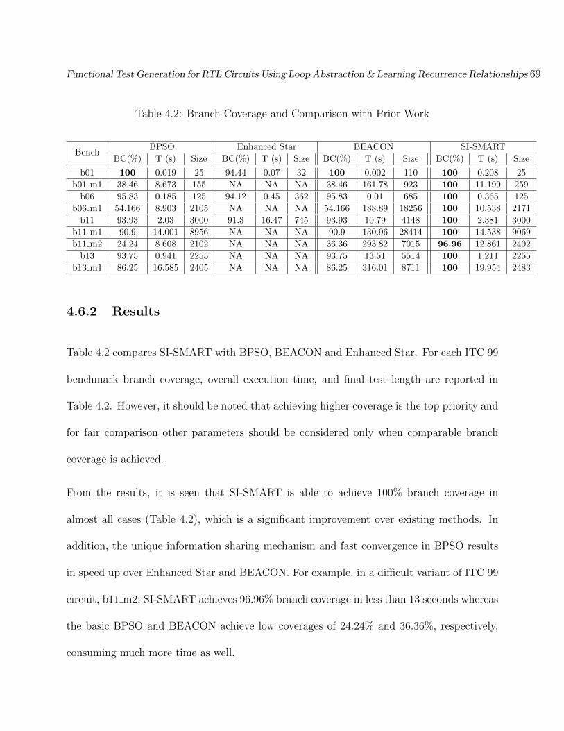
Functional Test Generation for RTL Circuits Using Loop Abstraction & Learning Recurrence Relationships 69
Table 4.2: Branch Coverage and Comparison with Prior Work
BenchBPSO Enhanced Star BEACON SI-SMART
BC(%) T (s) Size BC(%) T (s) Size BC(%) T (s) Size BC(%) T (s) Size
b01 100 0.019 25 94.44 0.07 32 100 0.002 110 100 0.208 25
b01 m1 38.46 8.673 155 NA NA NA 38.46 161.78 923 100 11.199 259
b06 95.83 0.185 125 94.12 0.45 362 95.83 0.01 685 100 0.365 125
b06 m1 54.166 8.903 2105 NA NA NA 54.166 188.89 18256 100 10.538 2171
b11 93.93 2.03 3000 91.3 16.47 745 93.93 10.79 4148 100 2.381 3000
b11 m1 90.9 14.001 8956 NA NA NA 90.9 130.96 28414 100 14.538 9069
b11 m2 24.24 8.608 2102 NA NA NA 36.36 293.82 7015 96.96 12.861 2402
b13 93.75 0.941 2255 NA NA NA 93.75 13.51 5514 100 1.211 2255
b13 m1 86.25 16.585 2405 NA NA NA 86.25 316.01 8711 100 19.954 2483
4.6.2 Results
Table 4.2 compares SI-SMART with BPSO, BEACON and Enhanced Star. For each ITC'99
benchmark branch coverage, overall execution time, and final test length are reported in
Table 4.2. However, it should be noted that achieving higher coverage is the top priority and
for fair comparison other parameters should be considered only when comparable branch
coverage is achieved.
From the results, it is seen that SI-SMART is able to achieve 100% branch coverage in
almost all cases (Table 4.2), which is a significant improvement over existing methods. In
addition, the unique information sharing mechanism and fast convergence in BPSO results
in speed up over Enhanced Star and BEACON. For example, in a difficult variant of ITC'99
circuit, b11 m2; SI-SMART achieves 96.96% branch coverage in less than 13 seconds whereas
the basic BPSO and BEACON achieve low coverages of 24.24% and 36.36%, respectively,
consuming much more time as well.

Functional Test Generation for RTL Circuits Using Loop Abstraction & Learning Recurrence Relationships 70
The example shown in Fig. 4.1 forms a subsection of the new process added in the b13
benchmark circuit to form b13 m1 circuit. For b13 m1, both basic BPSO and BEACON
fail to cover the target branch (in Fig. 4.1) thus resulting in lower design coverage when
compared to SI-SMART. A similar performance gap is observed for several other circuits as
well. Another difficult circuit available in ITC'99 benchmark suite is the b12 circuit. The
b12 circuit represents a Simon-says game and is memory intensive in nature. We plan to
handle memory based designs in future versions of SI-SMART.
Table 4.3: Execution Time & Unreachability Analysis
BenchExecution time (sec) for different phases of SI-SMART #BranchVerilator Static Analysis BPSO SBE SU FU
b01 0.067 0.189 0.019 0 0 0b01 m1 0.068 0.183 8.673 2.342 0 0
b06 0.068 0.180 0.185 0 1 0b06 m1 0.067 0.221 8.903 1.413 1 0
b11 0.072 0.184 2.03 0.167 1 1b11 m1 0.068 0.189 14.001 0.347 1 1b11 m2 0.070 0.182 8.608 4.071 1 1
b13 0.079 0.270 0.941 0 4 0b13 m1 0.087 0.343 16.58 3.026 5 0
Note: ** includes the time for formal phase and BPSO-HJ stage. SU and FUrepresent the number of structurally and functionally unreachable branches.
Table 4.3 reflects the execution time for different phases of SI-SMART and the number of
unreachable branches detected. In column 2, we report the time taken by Verilator for source-
to-source transformation. Column 3 and 4 reports the time consumed for statically analyzing
the DUT and runs of BPSO to maximize the branch coverage. Column 5 gives the total
time consumed by SI-SMART during CFG traversal using SBE and BPSO-HJ stage, a zero
in this column indicates that 100% branch coverage was achieved before reaching the formal

Functional Test Generation for RTL Circuits Using Loop Abstraction & Learning Recurrence Relationships 71
phase. Structurally and functionally unreachable (SU & FU) branches (in columns 6 and
7) detected by SI-SMART are marked as covered, thus increasing overall branch coverage.
4.7 Chapter Summary
This chapter focusses on tackling problems faced by techniques based on Bounded Model
Checking, Symbolic Execution and Simulation based methods in general. The presence of
loops typically limits the deterministic engines whereas large input space causes problems
for simulation based methods. SI-SMART tackles all these problems by eliminating the
need of both explicit unrolling of the control flow graph (CFG) and analysis of many cycles
as necessitated by traditional methods. This is achieved by abstracting loops present in
the design under test (DUT) and attempting to learn the recurrence relations among the
variables that directly or indirectly affect the target branch condition. An SMT solver is
used to find correlations between the inputs and the target branches. This learned knowledge
is later fed back to a combination of Binary Particle Swarm Optimization (BPSO) and
Hooke Jeeves method to attempt to reach the uncovered branches. SI-SMART is evaluated
on several difficult variants of ITC'99 benchmark circuits with significant improvements in
branch coverage, test sequence lengths and execution times over existing methods.
Chapter 5
Conclusion and Future Work
5.1 Conclusion
Test generation for RTL design validation is a challenging problem. In this thesis we have
addressed some of the problems associated with effective test generation to quickly achieve
high design coverage. In this regard, Particle Swarm Optimization based frameworks have
been proposed in this thesis. PSO is combined with information extracted from the design to
help generate input sequences for design validation. The two major contributions proposed
in this thesis can be summarized as follows:
� In the first contribution, we propose Particle Swarm Optimization based test genera-
tion technique for RTL design validation. The proposed method builds upon the fast
converging nature of the PSO swarm to quickly generate useful test sequences. To
72

Prateek Puri Chapter 5. Conclusion & Future Work 73
aid the test generation process, a graphical search technique is embedded in PSO to
provide important structural information of DUT. We have shown that our method is
highly effective in exploring the control state space by achieving high branch coverage
and offers significant advantage in terms of computational efficiency and test set size
over existing methods.
� In the second contribution, we have addressed the problems associated with tradi-
tional Bounded Model Checking (BMC) and symbolic execution based semi-formal
methods for test generation. Also the proposed technique overcomes the shortcomings
of simulation based methods. In the proposed method, we hybridize Binary Particle
Swarm and symbolic backward execution for RTL design validation. The proposed
method combines the fast convergence and scalability of a stochastic search method
and the completeness of a formal tool to generate test sequences. The main novelty
of SI-SMART is to prevent the need for formal circuit analysis of many cycles by ab-
stracting the loops and the ability to encounter information losses if any are due to
the loop abstraction. We have shown that our method is highly effective in the explo-
ration of control state space of the DUT and can achieve high coverage in very large
input search space as well. In several of the difficult benchmark circuits, significant
improvements were achieved.
Both the proposed methods have achieved better coverage in shorter times when compared
to the existing methods. The second framework proposes enhances to the first framework
and attempts to resolve branches which cannot be covered by PSO alone.

Prateek Puri Chapter 5. Conclusion & Future Work 74
5.2 Future Work
While developing the proposed frameworks we can came across several ideas worth exploring
as a part of future research work:
� Branch coverage is the metric used in both of the proposed frameworks. Although an
attempt is made to differentiate hard and easy branches in latter stages of BPSO, the
differentiation depends upon the performance of the particles in the swarm. Another
approach could be classifying toughness of branches by performing a static analysis on
DUT. The RTL design typically comprises of nested structures. Such nested structur-
ing could be useful to classify the hardness of a branch to be covered. Also branching
condition can be used to determine the probability of a branch to be covered. This
could be further explored.
� Both the proposed frameworks use Verilator for simulating the DUT. However usage
of Verilator doesnt allow for a generic test generation framework and wrappers have to
be modified for simulating different DUTs. Verilator is faster than other public domain
Verilog simulators. However, the overall test generation can be made faster if a FPGA
based approach is taken for test generation. PSO is a simple algorithm and can be
implemented on FPGA.
� Both the approaches use BPSO at their core. Since BPSO is a stochastic technique,
the length of final test sequences is typically longer than ideal. Certain compaction
strategies can be implemented to reduce the length of final test sequences.

Prateek Puri Chapter 5. Conclusion & Future Work 75
� The static analysis proposed in SI-SMART can be further improved to increase the
branch coverage for memory intensive circuits and pipelined circuits. Also, additional
information can be extracted from DUT to encounter loss of information due to loop
abstraction and help test generation.

Bibliography
[1] H. Foster, “The 2010 wilson research group functional verification study,” Aug 2013.
[2] G. E. Moore et al., “Cramming more components onto integrated circuits,” Proceedings
of the IEEE, vol. 86, no. 1, pp. 82–85, 1998.
[3] S. Devadas, A. Ghosh, and K. Keutzer, “An observability-based code coverage metric
for functional simulation,” in Proc. IEEE/ACM Intl Conf. on Computer-aided design,
pp. 418–425, 1997.
[4] M. Li, K. Gent, and M. S. Hsiao, “Design validation of rtl circuits using evolutionary
swarm intelligence,” in Proc. IEEE Intl Test Conf., pp. 1–8, 2012.
[5] L. Liu and S. Vasudevan, “Scaling input stimulus generation through hybrid static and
dynamic analysis of rtl,” ACM Trans. on Design Automation of Electronic Systems
(TODAES), vol. 20, no. 1, pp. 1–33, Nov. 2014.
[6] L. Liu and S. Vasudevan, “Efficient validation input generation in rtl by hybridized
source code analysis,” in Design, Automation & Test in Europe Conf., pp. 1–6, 2011.
[7] P. Puri and M. S. Hsiao, “Fast stimuli generation for design validation of rtl circuits
using binary particle swarm optimization,” 2015.
[8] S. Shyam and V. Bertacco, “Distance-guided hybrid verification with guido,” in Proc.
IEEE Design, Automation and Test in Europe Conf., pp. 1211–1216, 2006.
[9] K. Nanshi and F. Somenzi, “Guiding simulation with increasingly refined abstract
traces,” in Proc. Design Automation Conf., pp. 737–742, 2006.
[10] K. Gent and M. S. Hsiao, “Functional test generation at the rtl using swarm intelligence
and bounded model checking,” in Test Symposium (ATS), 2013 22nd Asian, pp. 233–
238, IEEE, 2013.
76
Prateek Puri Bibliography 77
[11] L.-T. Wang, C.-W. Wu, and X. Wen, VLSI test principles and architectures: design for
testability. Academic Press, 2006.
[12] W. Snyder, P. Wasson, and D. Galbi, “Verilator,” 2007.
[13] R. C. Eberhart and J. Kennedy, “A new optimizer using particle swarm theory,” in
Proceedings of the sixth international symposium on micro machine and human science,
vol. 1, pp. 39–43, New York, NY, 1995.
[14] M. Clerc and J. Kennedy, “The particle swarm-explosion, stability, and convergence in
a multidimensional complex space,” Evolutionary Computation, IEEE Transactions on,
vol. 6, no. 1, pp. 58–73, 2002.
[15] E. Elbeltagi, T. Hegazy, and D. Grierson, “Comparison among five evolutionary-based
optimization algorithms,” Advanced engineering informatics, vol. 19, no. 1, pp. 43–53,
2005.
[16] R. Hassan, B. Cohanim, O. De Weck, and G. Venter, “A comparison of particle swarm
optimization and the genetic algorithm,” in Proceedings of the 1st AIAA multidisci-
plinary design optimization specialist conference, pp. 18–21, 2005.
[17] Y. Shi and R. Eberhart, “A modified particle swarm optimizer,” in Evolutionary Com-
putation Proceedings, 1998. IEEE World Congress on Computational Intelligence., The
1998 IEEE International Conference on, pp. 69–73, IEEE, 1998.
[18] J. Kennedy and R. Mendes, “Population structure and particle swarm performance,”
2002.
[19] R. Mendes, J. Kennedy, and J. Neves, “The fully informed particle swarm: simpler,
maybe better,” Evolutionary Computation, IEEE Transactions on, vol. 8, no. 3, pp. 204–
210, 2004.
[20] J. Kennedy and R. C. Eberhart, “A discrete binary version of the particle swarm al-
gorithm,” in IEEE Intl Conf. Systems, Man, and Cybernetics, vol. 5, pp. 4104–4108,
1997.
[21] M. A. Khanesar, M. Teshnehlab, and M. A. Shoorehdeli, “A novel binary particle swarm
optimization,” in Control & Automation, 2007. MED’07. Mediterranean Conference on,
pp. 1–6, 2007.

Prateek Puri Bibliography 78
[22] S. Mirjalili and A. Lewis, “S-shaped versus v-shaped transfer functions for binary parti-
cle swarm optimization,” Swarm and Evolutionary Computation, vol. 9, pp. 1–14, April
2013.
[23] R. Hooke and T. A. Jeeves, ““direct search”solution of numerical and statistical prob-
lems,” Journal of the ACM (JACM), vol. 8, no. 2, pp. 212–229, April 1961.
[24] R. M. Lewis, V. Torczon, and M. W. Trosset, “Direct search methods: then and now,”
Journal of computational and Applied Mathematics, vol. 124, no. 1, pp. 191–207, Dec.
2000.
[25] E. M. Clarke, M. Fujita, S. P. Rajan, T. Reps, S. Shankar, and T. Teitelbaum, Program
slicing of hardware description languages. Springer, 1999.
[26] S. Bagri, K. Gent, and M. S. Hsiao, “Signal domain based reachability analysis in rtl
circuits,” in Quality Electronic Design (ISQED), 2015 16th International Symposium
on, pp. 250–256, IEEE, 2015.
[27] F. E. Allen, “Control flow analysis,” in ACM Sigplan Notices, vol. 5, pp. 1–19, ACM,
1970.
[28] B. Alpern, M. N. Wegman, and F. K. Zadeck, “Detecting equality of variables in pro-
grams,” in Proc. ACM SIGPLAN-SIGACT Symp. on Principles of Programming Lan-
guages, pp. 1–11, 1988.
[29] V. Ganesh, Decision procedures for bit-vectors, arrays and integers. PhD thesis, Stanford
University, 2007.
[30] B. Alizadeh and M. Fujita, “Guided gate-level atpg for sequential circuits using a high-
level test generation approach,” in Proceedings of the 2010 Asia and South Pacific
Design Automation Conference, pp. 425–430, IEEE Press, 2010.
[31] S. Prabhu, M. S. Hsiao, L. Lingappan, and V. Gangaram, “A smt-based diagnostic test
generation method for combinational circuits,” in VLSI Test Symposium (VTS), 2012
IEEE 30th, pp. 215–220, IEEE, 2012.
[32] L. De Moura and N. Bjørner, “Z3: An efficient smt solver,” in Tools and Algorithms for
the Construction and Analysis of Systems, pp. 337–340, Springer, 2008.
[33] L. A. Clarke, “A system to generate test data and symbolically execute programs,”
IEEE Trans. Software Engineering, no. 3, pp. 215–222, Sept. 1976.
Prateek Puri Bibliography 79
[34] S. Chandra, S. J. Fink, and M. Sridharan, “Snugglebug: a powerful approach to weakest
preconditions,” in ACM Sigplan Notices, vol. 44, pp. 363–374, 2009.
[35] V. Kelner, F. Capitanescu, O. Leonard, and L. Wehenkel, “A hybrid optimization tech-
nique coupling an evolutionary and a local search algorithm,” Journal of Computational
and Applied Mathematics, vol. 215, no. 2, pp. 448–456, 2008.
[36] S. Davidson, “Itc’99 benchmark circuits-preliminary results,” in Proc. Intl Test Conf.,
p. 1125, 1999.
[37] F. Corno, M. S. Reorda, and G. Squillero, “Rt-level itc’99 benchmarks and first atpg
results,” IEEE Design & Test of computers, vol. 17, no. 3, pp. 44–53, 2000.
[38] H. Li, Y. Min, and Z. Li, “An rt-level atpg based on clustering of circuit states,” in Test
Symposium, 2001. Proceedings. 10th Asian, pp. 213–218, IEEE, 2001.
[39] M. S. Hsiao and S. T. Chakradhar, “State relaxation based subsequence removal for fast
static compaction in sequential circuits,” in Design, Automation and Test in Europe,
1998., Proceedings, pp. 577–582, IEEE, 1998.
[40] M. S. Hsiao, E. M. Rudnick, and J. H. Patel, “Fast static compaction algorithms for se-
quential circuit test vectors,” Computers, IEEE Transactions on, vol. 48, no. 3, pp. 311–
322, Mar. 1999.
[41] M. S. Hsiao, E. M. Rudnick, and J. H. Patel, “Sequential circuit test generation using
dynamic state traversal,” in Proceedings of the 1997 European conference on Design and
Test, p. 22, IEEE Computer Society, 1997.
[42] X. Chuanpei, L. Zhi, and M. Wei, “Study of differential evolution on atpg,” in Commu-
nications, Circuits and Systems Proceedings, 2006 International Conference on, vol. 3,
pp. 2084–2087, IEEE, 2006.
[43] Y. Hou, C. Zhao, and Y. Liao, “A new method of test generation for sequential circuits,”
in Communications, Circuits and Systems Proceedings, 2006 International Conference
on, vol. 4, pp. 2181–2185, IEEE, 2006.
[44] D. Krishnaswamy, M. S. Hsiao, V. Saxena, E. M. Rudnick, J. H. Patel, and P. Banerjee,
“Parallel genetic algorithms for simulation-based sequential circuit test generation,”
in VLSI Design, 1997. Proceedings., Tenth International Conference on, pp. 475–481,
IEEE, 1997.
Prateek Puri Bibliography 80
[45] M. S. Hsiao, E. M. Rudnick, and J. H. Patel, “Dynamic state traversal for sequential
circuit test generation,” ACM Transactions on Design Automation of Electronic Systems
(TODAES), vol. 5, no. 3, pp. 548–565, July 2000.
[46] K. Gent and M. S. Hsiao, “Dual-purpose mixed-level test generation using swarm intel-
ligence,” in Test Symposium (ATS), 2014 IEEE 23rd Asian, pp. 230–235, IEEE, 2014.
[47] F. M. De Paula and A. J. Hu, “An effective guidance strategy for abstraction-guided
simulation,” in Proc. Design Automation Conference, pp. 63–68, 2007.
[48] P. Puri and S. Ghosh, “A hybrid optimization approach for pi controller tuning based
on gain and phase margin specifications,” Swarm and Evolutionary Computation, vol. 8,
pp. 69–78, Feb. 2013.
[49] K. E. Parsopoulos and M. N. Vrahatis, “Initializing the particle swarm optimizer using
the nonlinear simplex method,” in Advances in Intelligent Systems, Fuzzy Systems,
Evolutionary Computation, pp. 216–221, WSEAS Press, 2002.
[50] W. Wu and M. S. Hsiao, “Efficient design validation based on cultural algorithms,” in
Design, Automation and Test in Europe,, pp. 402–407, 2008.
[51] A. Parikh, W. Wu, and M. S. Hsiao, “Mining-guided state justification with partitioned
navigation tracks,” in Proc. Intl Test Conf., pp. 1–10, 2007.
[52] M. Li and M. S. Hsiao, “An ant colony optimization technique for abstraction-guided
state justification,” in Proc. Intl Test Conf., pp. 1–10, 2009.
[53] M. S. Hsiao, E. M. Rudnick, and J. H. Patel, “Alternating strategies for sequential circuit
atpg,” in Proceedings of the 1996 European conference on Design and Test, pp. 368–374,
IEEE Computer Society, 1996.