design pressure issues of super-frs dipole cryogenic department in common system (cscy), gsi,...
TRANSCRIPT
Design pressure issues of Super-FRS dipole
CrYogenic Department in Common System (CSCY), GSI, Darmstadt
Yu Xiang, Hans Mueller*
* Primay Beam Magnet Technology (PBMT), GSI
Magnet test meeting at CERN (08-01-2015 )

It is quite different from the proposed way to cooldown the dipole (and multiplet) for GSI local cryogenics and test at CERN
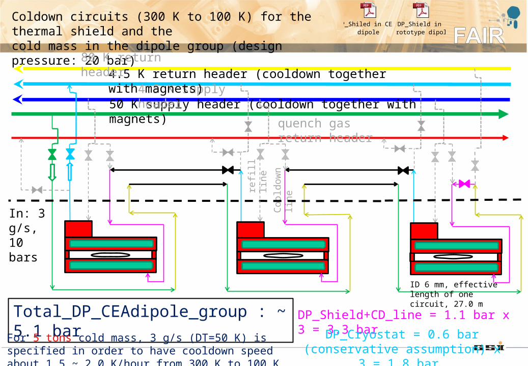
The proposed single circuit to cooldown the dipole (and multiplet) for local cryogenics at FAIR and test at CERN
Coo
ldow
n li
ne
In: 3 g/s, 10 bars
Total_DP_CEAdipole_group : ~ 5.1 bar
refi
ll li
ne
Coldown circuits (300 K to 100 K) for the thermal shield and the cold mass in the dipole group (design pressure: 20 bar)
50 K supply header (cooldown together with magnets)4.5 K supply header
4.5 K return header (cooldown together with magnets)80 K return header
quench gas return header
DP_Shield+CD_line = 1.1 bar x 3 = 3.3 bar
DP_Cryostat = 0.6 bar (conservative assumption) x 3 = 1.8 bar
For 5 tons cold mass, 3 g/s (DT=50 K) is specified in order to have cooldown speed about 1.5 ~ 2.0 K/hour from 300 K to 100 K
ID 6 mm, effective length of one circuit, 27.0 m
DP_Shiled in CEA dipole
DP_Shield in Prototype dipole

48.8 mm
58.8 mm
62 mm
52.2 mm
1.5 g/s
Pressure drop estimation in one coil case of dipole during cooldown (geometry from prototype dipole)
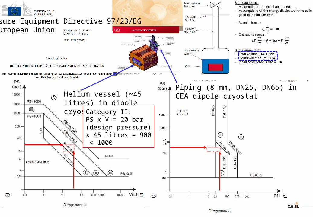
Pressure Equipment Directive 97/23/EG - European Union
Helium vessel (~45 litres) in dipole cryostat
Piping (8 mm, DN25, DN65) in CEA dipole cryostat
Category II:PS x V = 20 bar (design pressure) x 45 litres = 900 < 1000

Category I:PS x V = 4 bar (design pressure) x 45 litres = 180 < 200
Different design pressures: 4 bar for helium vessel and 20 bar for shield circuit.
Helium vessel (~45 litres) in dipole cryostat
Piping (8 mm, DN25, DN65) in CEA dipole cryostat

shield circuit inlet: ~ 1 g/s, 10 bars
cold mass circuit: ~ 2.0 g/s, 4.0 bars
In: 3 g/s, 10 bars
DP_shield_dipole_group = ~ 0.5 bar
refi
ll li
ne
Separate cooldown circuits (300 K to 100 K) for the thermal shield and the cold mass in the dipole group due to different design pressures (4 bar for helium vessel and 20 bar for shield circuit)
50 K supply header4.5 K supply header (cooldown together with magnets)
4.5 K return header80 K return header (cooldown together with magnets)
quench gas return header
Coo
ldow
n li
ne
DP_Shield = ~ 0.16 bar x 3 = ~ 0.5 bar
DP_Cryostat = 0.92 bar (conservative assumption) x 3 = 2.8 bar DP_coldmass_dipole_group = ~ 2.8 bar
Return flow: ~ 2.0 g/s, 1.2 bars
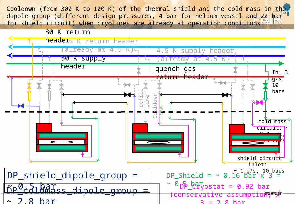
shield circuit inlet: ~ 1 g/s, 10 bars
cold mass circuit: ~ 2.0 g/s, 4.0 bars
In: 3 g/s, 10 bars
DP_shield_dipole_group = ~ 0.5 bar
refi
ll li
ne
Cooldown (from 300 K to 100 K) of the thermal shield and the cold mass in the dipole group (different design pressures, 4 bar for helium vessel and 20 bar for shield circuit) when cryolines are already at operation conditions
50 K supply header4.5 K supply header (already at 4.5 K)
4.5 K return header (already at 4.5 K)80 K return header
quench gas return header
Coo
ldow
n li
ne
DP_Shield = ~ 0.16 bar x 3 = ~ 0.5 bar
DP_Cryostat = 0.92 bar (conservative assumption) x 3 = 2.8 bar DP_coldmass_dipole_group = ~ 2.8 bar

Coo
ldow
n li
ne
In: 50 g/s, 10 bar
refi
ll li
ne
Coldown circuits (300 K to 100 K) for the thermal shield and the cold mass in the multiplet group before target (design pressure: 20 bar)
50 K supply header4.5 K supply header
4.5 K return header (cooldown together with magnets)80 K return header (cooldown together with magnets)
quench gas return header
DP_Shield+CD_line = 1.0 bar x 3 = 3.0 barDP_Cryostat = 0.3 bar x 3 = 0.9 bar
ID 28.5 mm, effective length of one circuit, 54.0 m
For 102 tons cold mass, 50 g/s (DT=50 K for individual cryostat) is specified to have cooldown rates about 1.5 ~ 2.0 K/hour from 300 K to 100 K
Total_DP_3xmultiplets_group = 4.0 bar
Total_DP_2xmultiplets_group = 2.7 bar

LN2 Precooler for LHC test benches in SM-18

Supply pressure: ~ 10 barReturn pressure: 5.0 ~ 6.0 bar
to mid pressure return of compressors
Return pressure: ~ 1.2 bar
to low pressure return of compressors
One more return flow stream in heater exchangers design for precooler than the usual cases

Helium pressure rise due to thermal energy deposition under different liquid helium volumes and ullages with the assumption of isochoric process

Summary
CEA Dipole
Same design pressures for shield and coil case circuits [bara]
Different design pressures for shield and coil case circuits [bara]
Shield circuit Coil case circuit Shield circuit Coil case circuit
20 20 20 ~ 5 (e.g.)
PED pressure vessel category
Category II for CEA dipole coil circuitreduction to category I is possible but with very low design pressure < 5 bara
Cooldown flow(3.0 g/s)
in series for test at CERN and machine at FAIR
must be in paralle (CEA design: 1.5 ~ 2.0 g/s for coils and 1.0 g/s for shield)
Individual cryostat test at CERN
DP_shield: ~ 1.1 bar DP_coils: ~ 0.6 bar DP_shield: ~ 0.2 bar DP: ~ 0.9 bar for coils
Total DP ~ 1.7 bar for dipole cooldown (10 bar supply / 8.3 bar return);Total DP ~ 1.3 bar for multiplet cooldown with 50 g/s
10 bar supply / 9.8 bar return
4 bar supply / 3.1 bar return
PrecoolerOne common return flow from cooldown of
dipole and multipletTwo return flow streams at different pressures
Set pressure for safety valve
20 < 4 bara

Thank you very much
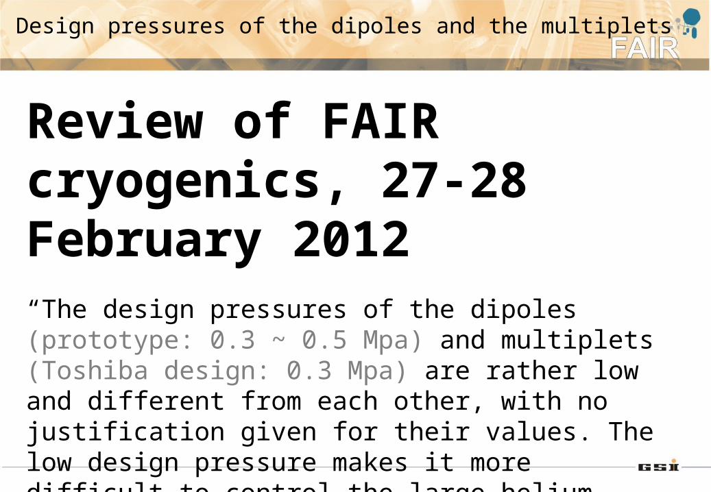
Review of FAIR cryogenics, 27-28 February 2012“The design pressures of the dipoles (prototype: 0.3 ~ 0.5 Mpa) and multiplets (Toshiba design: 0.3 Mpa) are rather low and different from each other, with no justification given for their values. The low design pressure makes it more difficult to control the large helium inventory in case of operational problems, which could result in large helium loss.”
Design pressures of the dipoles and the multiplets

Review of FAIR cryogenics, 27-28 February 2012“There seems to be a lack of understanding and late changes in the cooling method of these magnets. Whilst final cool-down is performed by injecting liquid helium into the bottom of the helium vessel and recovering vapour in the service turret, the magnets normally operate in baths of saturated helium with a controlled level ensuring complete immersion of the coils. Such a level control is reasonably easy to achieve by transferring liquid helium from a phase separator through an insulated line to the top of the bath which then operates as a decanter of the liquid from the vapour coming from the transfer losses. Feeding at the bottom of the bath prevents this decanting and may disrupt the level control.”
LHe refill from the bottom or the top

Preliminary Design Review for Super-FRS Dipole (03-07-2014)