interface issues on super-frs magnets test at cern cryogenic department in common system (cscy) gsi,...
TRANSCRIPT
Interface issues on Super-FRS magnets test at CERN
CrYogenic Department in Common System (CSCY) GSI, Darmstadt
Yu Xiang
Meeting for Super-FRS magnets test at GSI (15.10.2014)
1. Installation of safety valve in Upright and Non-Upright positions;
2. Pressure drop over release line when safety valve opens with the maximum discharge flow;
3. Reaction forces on release line when safety valve opens with the maximum discharge flow;
Meeting for Super-FRS magnets test at GSI (15.10.2014)

Installation of safety valve in upright and Non-Upright positions
6.2.5.2 Exceptions in Codes and Standards which allow the Non-Upright Position
6.2.5 Mounting Position – Horizontal Installation
6.2.5.1 Codes and Standards which direct an installation in the Upright Position
LESER EHB_6.2-Installation-of-Safety-Valv
Basic Function of a Spring Loaded Safety
a typical functional curve of opening of a spring loaded safety valve of safety valve (http://www.leser.com/en/tools/safety-valve-tutorial/spring-loaded-safety-valve-from-leser.html)
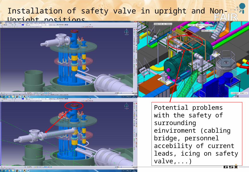
Installation of safety valve in upright and Non-Upright positions
Potential problems with the safety of surrounding einviroment (cabling bridge, personnel accebility of current leads, icing on safety valve,...)
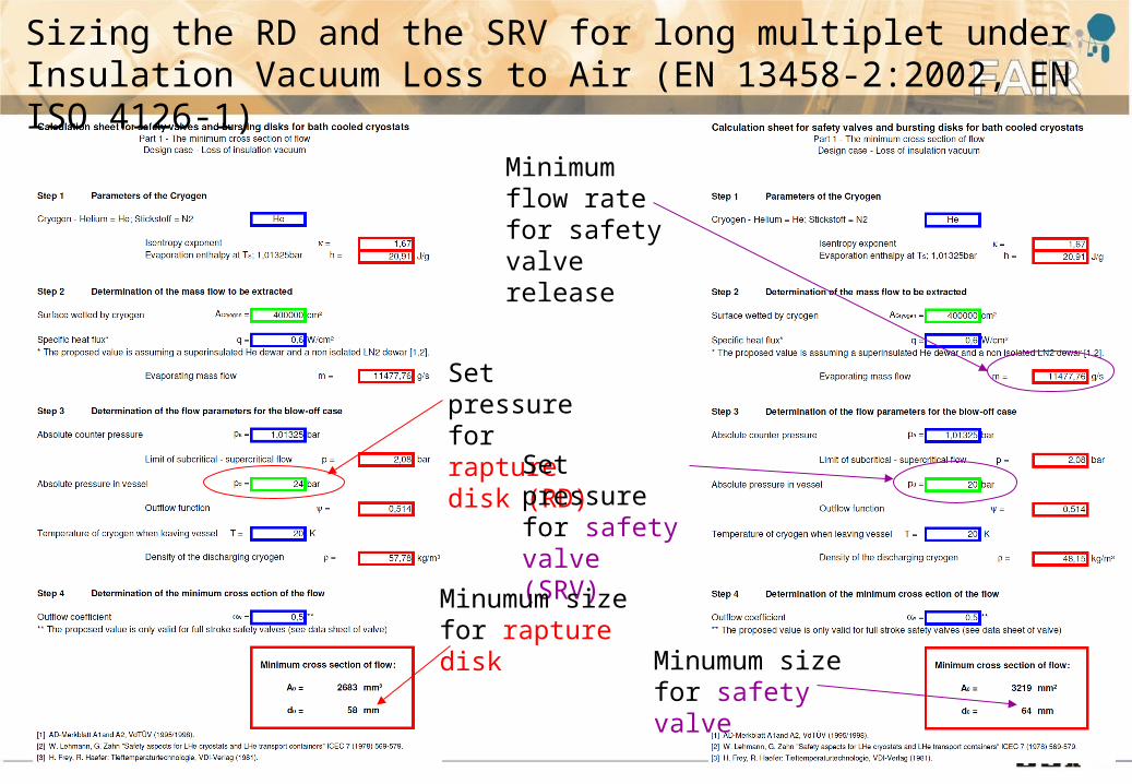
Sizing the RD and the SRV for long multiplet under Insulation Vacuum Loss to Air (EN 13458-2:2002, EN ISO 4126-1)
Set pressure for rapture disk (RD)
Set pressure for safety valve (SRV)
Minumum size for safety valve
Minumum size for rapture disk
Minimum flow rate for safety valve release

Flow over release line when safety valve opens with the discharge flow at 12.0 kg/s at 20 bar and 10 K
12 kg/s at 20 bar and 10 K
flow in bend to simulate the flow in safety valve
Temperature profile after flow gets stable
Flow streamline after flow gets stable
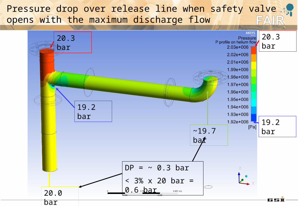
Pressure drop over release line when safety valve opens with the maximum discharge flow
20.0 bar
20.3 bar20.3 bar
19.2 bar
19.2 bar
~19.7 bar
DP = ~ 0.3 bar
< 3% x 20 bar = 0.6 bar
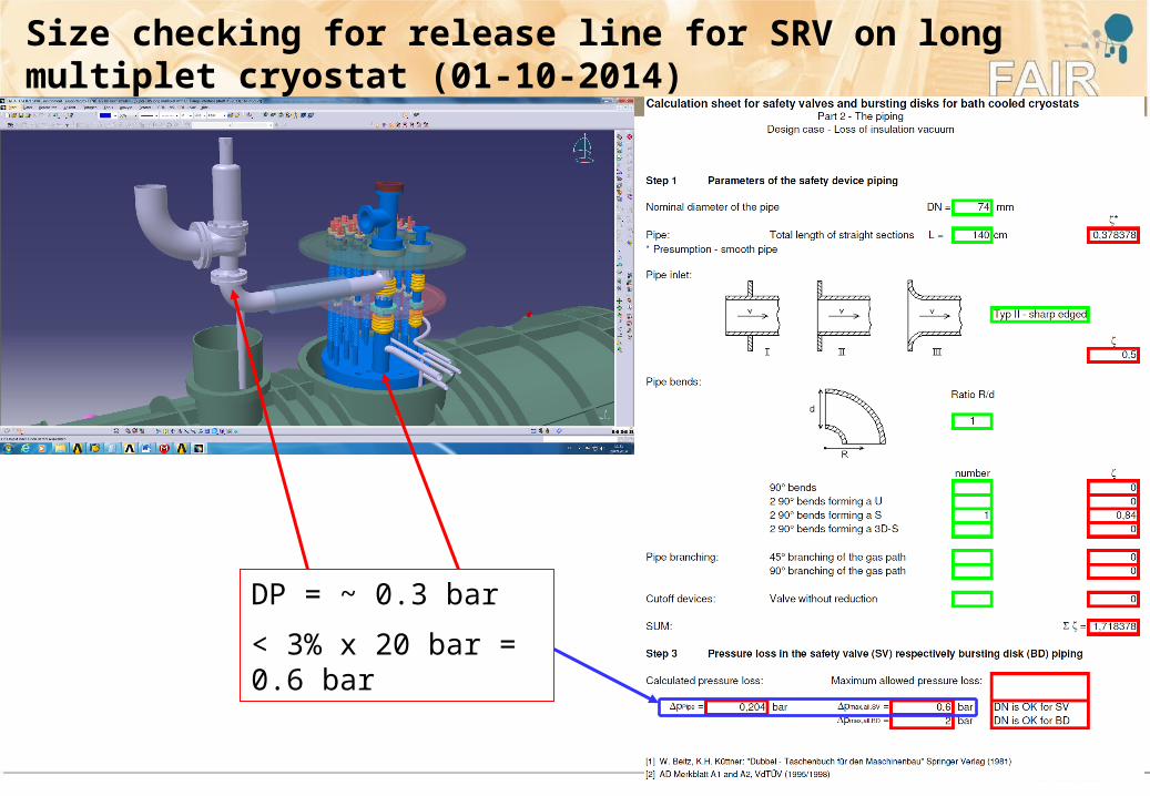
Size checking for release line for SRV on long multiplet cryostat (01-10-2014)
DP = ~ 0.3 bar
< 3% x 20 bar = 0.6 bar
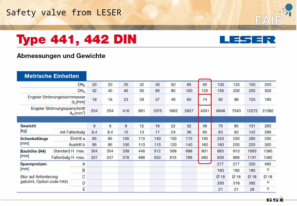
Safety valve from LESER
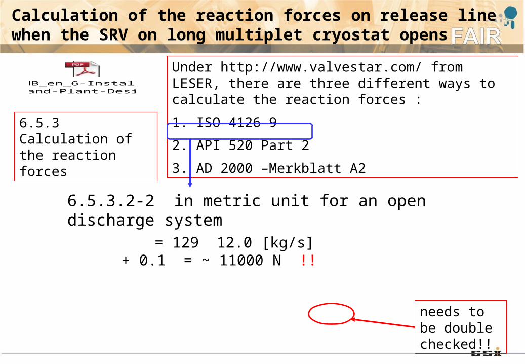
Calculation of the reaction forces on release line when the SRV on long multiplet cryostat opens
Under http://www.valvestar.com/ from LESER, there are three different ways to calculate the reaction forces :
1. ISO 4126-9
2. API 520 Part 2
3. AD 2000 –Merkblatt A2
EHB_en_6-Installation-and-Plant-Design_LE
6.5.3 Calculation of the reaction forces
= 129 12.0 [kg/s] + 0.1 = ~ 11000 N !!
6.5.3.2-2 in metric unit for an open discharge system
needs to be double checked!!
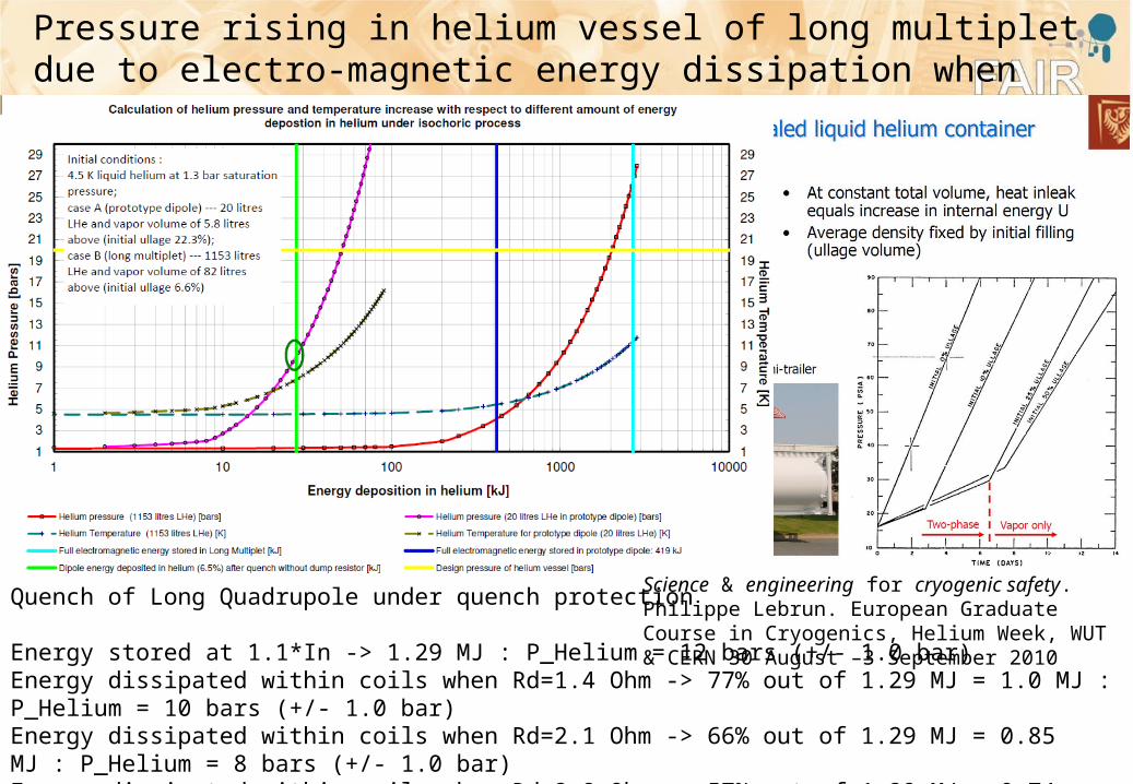
Pressure rising in helium vessel of long multiplet due to electro-magnetic energy dissipation when the long quadrupole quenches.
Quench of Long Quadrupole under quench protection
Energy stored at 1.1*In -> 1.29 MJ : P_Helium = 12 bars (+/- 1.0 bar) Energy dissipated within coils when Rd=1.4 Ohm -> 77% out of 1.29 MJ = 1.0 MJ : P_Helium = 10 bars (+/- 1.0 bar) Energy dissipated within coils when Rd=2.1 Ohm -> 66% out of 1.29 MJ = 0.85 MJ : P_Helium = 8 bars (+/- 1.0 bar) Energy dissipated within coils when Rd=2.8 Ohm -> 57% out of 1.29 MJ = 0.74 MJ : P_Helium = 7 bars (+/- 1.0 bar) Energy dissipated within coils when Rd=4 Ohm -> 44% out of 1.29 MJ = 0.57 MJ : P_Helium = 5 bars (+/- 1.0 bar)
Science & engineering for cryogenic safety. Philippe Lebrun. European Graduate Course in Cryogenics, Helium Week, WUT & CERN 30 August –3 September 2010
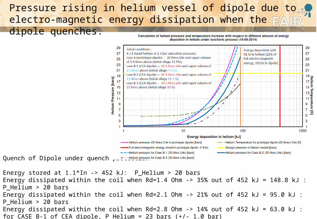
Pressure rising in helium vessel of dipole due to electro-magnetic energy dissipation when the dipole quenches.
Quench of Dipole under quench protection
Energy stored at 1.1*In -> 452 kJ: P_Helium > 20 barsEnergy dissipated within the coil when Rd=1.4 Ohm -> 35% out of 452 kJ = 148.8 kJ : P_Helium > 20 barsEnergy dissipated within the coil when Rd=2.1 Ohm -> 21% out of 452 kJ = 95.0 kJ : P_Helium > 20 barsEnergy dissipated within the coil when Rd=2.8 Ohm -> 14% out of 452 kJ = 63.0 kJ : for CASE B-1 of CEA dipole, P_Helium = 23 bars (+/- 1.0 bar) for CASE B-2 of CEA dipole, P_Helium = 17 bars (+/- 1.0 bar) for CASE B-3 of CEA dipole, P_Helium = 13 bars (+/- 1.0 bar)
Thank you for your attention!