design of wood members under combined load · pdf filedesign of wood members under combined...
TRANSCRIPT

DESIGN OF WOOD MEMBERS UNDER COMBINED LOAD
By John J. Zahn,1 M. ASCE
ABSTRACT: A new design criterion for wood members under combined axial and bending loads is proposed. The new equation covers biaxial bending, axial load, and water ponding. It employs Ylinen's column formula for beam or column buckling, and replaces the linear interaction equation with more accurate equations based on recent test data and results of elastic stability analysis. Despite its simplicity, the proposed criterion is more general, more rational and more accurate than the existing design criterion.
INTRODUCTION
Modern engineered wood structures require more accurate design criteria in order to perform more efficiently without compromising safety or serviceability. The current design equations for wood members under combined bending and axial load (Fig. 1), as contained in the National Design Specification (NDS) (NFPA 1982), have remained largely unchanged since they were first proposed by Newlin and Trayer (1941). Those equations were based on limited data for clear wood or for large timbers (Newlin and Gahagan 1930), at a time when there was no rational analysis available for buckling under combined loading. They are also somewhat lacking in generality because the interactions of biaxial bending are not modeled.
The objective of the present work is to provide a general design criterion for wood members under combined load that would be: (1) Based on recent combined-load test data for in-grade lumber; and (2) compatible with elastic buckling theory for long slender members. Recent test data for in-grade columns (Buchanan 1984; Galambos 1968; Malhotra 1969, 1972; Neubauer 1969, 1972) indicate that our present design criterion is unconservative, while data for in-grade beam-columns (Buchanan 1984; Johns and Buchanan 1982; Malhotra 1979; Zahn 1982, 1984) show that the current interaction equation does a poor job of modeling failure over a large range of slenderness values. The correct analysis of secondary moments, or effect," has been in the literature for several decades (Galambos 1968) and has been a part of the steel code for over 20 years, but has not yet been adopted for wood design. Simple and accurate column design criteria are available (Malhotra 1969, 1972; Ylinen 1956), and the writer has recently analyzed the elastic stability of simply supported slender members under combinations of axial compression, biaxial lateral loading and water ponding (when used in flat roof constructions) (Zahn 1985). All of these results are used in the new formulas to be proposed here.
1Research General Engr., U.S. Dept. of Agr., Forest Serv., Forest Products Lab., 1 Gifford Pinchot Dr., Madison, WI 53705-2398.
Note.-Discussionopen until February 1, 1987. To extend the closing date one month, a written request must be filed with the ASCE Manager of Journals. The manuscript for this paper was submitted for review and possible publication on July 17, 1985. This paper is part of the Journal of Structural Engineering, Vol. 112, No. 9, September, 1986.
2109

FIG. 1.-Exampleof Biaxial Beam-Column: Everything Associated with Edgewise Bending Has Subscript 1 and Flatwise Has Subscript 2
This report starts with the simple case of ”Design Criteria for Single Loads,” although the main result is a new interaction equation in the section ”Design Criteria for Combined Loads.” There the PA effect is accounted for by moment modification factors which have been generalized to include deformations caused by axial compression, primary bending moment, and water ponding. These factors are the avenue through which all buckling modes are modeled. Moment modification factors are also presented for the tensile PA effect, but only for the case of uniaxial bending and axial tension. Biaxial bending and tension has not been investigated.
Current design criteria are presented and critiqued in each section after which a new criterion is proposed and discussed. Finally, both current and proposed criteria are compared to test data and their modeling errors presented at various slenderness ratios.
DESIGN CRITERIA FOR SINGLE LOADS
Here we consider either bending or axial load. The current design criteria are in sections 3.3, 3.6, 3.7, and 3.9 of the NDS.
Current Formulas
(1)
(2)
(3) in which f = actual stress; F = allowable stress; subscripts t, c, and b denote tension; compression, and bending; and a prime denotes adjustment for slenderness. These adjustments are given in NDS sections 3.3.3 and 3.7.3. The reductions for slenderness are:
(4)
2110

(5)
(6)
(7)
(8)
(9)
in which le = effective length, d = depth of cross section, E = modulus of elasticity
(10)
(11)
(12)
and b = width of cross section. The values 2.74 and 3.3 are safety factors and are not usually explicitly shown. Allowable stresses are tabulated by species and grade in the supplement to the NDS “Design Values for Wood Construction.”
Critique The reductions for slenderness, Eqs. 4-12, are open to three objec
tions:
1. The Forest Products Laboratory (FPL) fourth-power parabola (Eqs. 5, 8) was based on data for large timbers (Newlin and Gahagan 1930) and clear Sitka spruce (Newlin and Trayer 1941). It is unconservative for in-grade lumber (Buchanan 1984; Johns and Buchanan 1982; Malhotra 1969, 1972; Neubauer 1969, 1972). Fig. 2 shows in-grade data for columns, and both present (dashed line) and proposed (solid line) formulas. (The data from Buchanan 1984 and Johns and Buchanan 1982
2111

FIG. 2.-Comparisonof Ylinen’s Column Formula with c = 0.8 and Data from VariousSources
were extrapolated to zero eccentricity here.) The error in the present formula is about 25% at L/d =
2. There are three separate criteria for short, intermediate, and long members. This complicates the programming of the design criteria on a programmable calculator. A single formula would be preferred, and would avoid the discontinuity at the boundary between short and intermediate.
3. The elastic buckling of beams has a greater factor of safety than does the elastic buckling of columns. This is the result of an accumulation of worst-case assumptions in the analysis of elastic buckling of beams. Beams and columns should be treated alike.
Proposed Reduction for Slenderness Allowable stresses F'c and F'b would both be calculated from Ylinen’s
column formula (Ylinen 1956):
(13)
in which c is an adjustable constant between zero and one; a double prime denotes elastic buckling stress; and factor of safety = 2.74. Eq.
2112
(
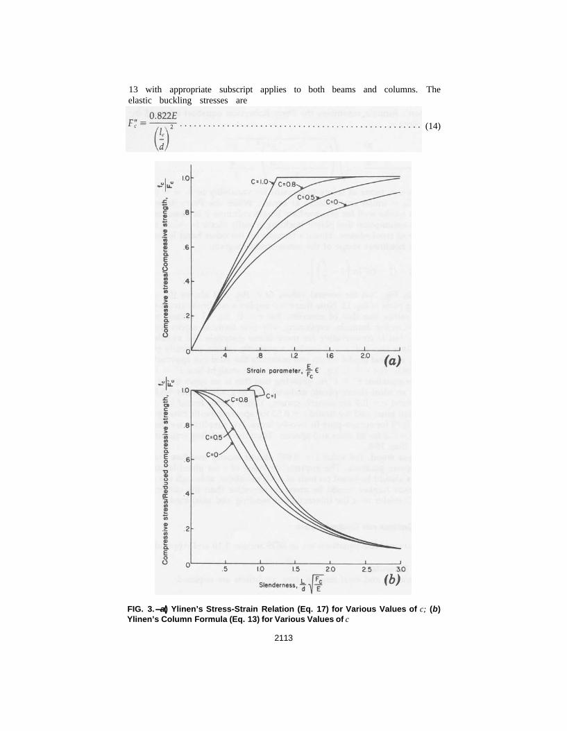
13 with appropriate subscript applies to both beams and columns. The elastic buckling stresses are
(14)
FIG. 3.-a) Ylinen’s Stress-Strain Relation (Eq. 17) for Various Values of c; (b) Ylinen’s Column Formula (Eq. 13) for Various Values of c
2113

(15)
Ylinen’s formula resembles the Perry-Robertson equation adopted in Great Britain:
(16)
in which = factor of safety to account for variability in E, m = (6C0)/ d; and C0 = initial crookedness at center. While the Perry-Robertson equation works well for intermediate length columns it is based on the fictitious assumption that plastic buckling is really elastic buckling in the presence of crookedness. Ylinen’s formula on the other hand is derived from the nonlinear shape of the stress-strain diagram:
(17)
plotted in Fig. 3(a) for several values of c. Fig. 3(b) shows the corresponding plots of Eq. 13. Note that c = 0 implies a nonlinear stress-strain relation rather like that of concrete. For c = 0, Eq. 13 reduces to the Rankine-Gordon formula, explaining why that formula works well for concrete, but is conservative for more linear materials like metals and wood. Note also that c = 1 implies a perfectly elastic, perfectly plastic material, an ideal model which real materials like steel can approach but never reach. For c = 1, Eq. 13 reduces to the straight line F' = F and the Euler equation F' = showing that this is an upper bound valid only for an ideal elastic-plastic material. For in-grade lumber Malhotra (1972) found c = 0.9 for eastern spruce, Ylinen (1956) found c = 0.875 for Finnish pine, and we found c = 0.82 for spruce-pine-fir two-by-sixes and c = 0.75 for spruce-pine-fir two-by-fours. For simplicity we decided to take c = 0.8 for all sizes and species. Then the modeling error on Fig. 2 is less than 10%.
For clear wood, the value c = 0.957 almost exactly matches the FPL fourth-power parabola. The appropriate value of c for glued-laminated members should be based on tests of such members, although the value for in-grade lumber would be more conservative than the current criterion. Consider next the interaction of bending and axial load.
DESIGN CRITERIA FOR COMBINED LOAD
The current NDS equations are in NDS section 3.10 and Appendix H.
Current Formulas For bending and axial tension, two conditions are required:
(18)
2114

(19)
in which sub t denotes tension and F'b is given in Eqs. 7-9. For bending and eccentric axial compression
(20)
in which e is eccentricity, and J is a number between zero and one, such that
(21)
and K is defined by Eq. 10.
Critique Eqs. 18 and 20 are linear interaction equations. Eq. 20 has some mod
ification for the effect. Eq. 19 attempts to account for the stabilizing effect of ft upon lateral-torsional buckling. These equations, or something very similar, have served well for many years. However, they are open to three criticisms:
1. The linear interaction equation lacks rational justification. 2. The modification for the effect is incorrect and inconsistent with
the design of other engineering materials. 3. Biaxial bending is not considered.
Linear Interaction Equation.-This failure criterion was adopted as a conservative measure to serve until more complete information became available. Its use has tended to obscure the fact that for short members it serves as a strength criterion and for long members it serves as a stability criterion. There is now sufficient strength data to write a more accurate strength criterion and an analytical solution is available for the stability criterion. Neither of these are linear, as will be shown later.
Effect. —It has been well known for several decades (Galambos 1968) that a compressive axial force Pc amplifies the bending moment of lateral loads:
(22)
in which M = the nominal bending moment (caused by lateral loads); = the actual bending moment; and P"c = the elastic buckling value of
Pc. Comparing Eq. 22 and the second term of Eq. 20 it is seen that the current criterion Eq. 22 is unconservative for le/d > This value is typically about 28.
2115

Similarly, an axial tensile force Pt decreases the bending moment:
(23)
P"c appears in both Eqs. 22 and 23 for the sole reason that the nominal bent shape was approximated by the shape of a buckled column. Both equations are valid for short as well as long members. Of course, in Eq. 22 approaches infinity as Pc approaches P"c, but this cannot be taken literally unless the member is long enough to buckle elastically, in which case the moment modification factor automatically models buckling.
Thus, because bending stress is proportional to bending moment, both the tensile and the compressive combined load design equations should have a moment modification factor on fb so that actual bending stress is compared to allowable bending stress in the design equation. Because this automatically models buckling in the compressive case, one immediately deduces that the design equation itself should be a strength criterion based upon data from short test specimens. That is, if is a strength criterion
(24)
valid for short members, then
(25)
in which = a moment modification factor, will serve as both a strength and a stability criterion and be valid for members of any length.
Biaxial Bending. –If biaxial bending is present, then the primary bending moment M1 (edgewise) will have an effect like the PA effect upon the lateral bending moment M2 (flatwise). That is, there should be a moment modification factor on M2 caused by M1. The present NDS in silent on the subject of biaxial bending but loadings such as those in Fig. 4 are common in space frames such as electric transmission towers. The proposed equations to be presented next contain two moment modification factors, one on the edgewise bending stress and one on the flatwise bending stress which includes the interaction of biaxial bending. This latter term shall be omitted from the proposed equation for combined bending and tension because it is based on an approximation which is conservative only when the axial force is compressive. The subject of combined tension and biaxial bending requires further study.
Proposed Interaction Equations For bending and axial tension
(26)
where sub one denotes edgewise as in Fig. 1, is a moment modification factor
2116

( FIG. 4 -a) Simply Supported Beam under Biaxial Bending; (b) Simply Supported Beam-Column under Biaxial Bending Caused by Eccentricity and Lateral Load (Ends Are Assumed to Be Supported Against Axial Rotation)
(27)
(28)
and d1 = depth of member. For bending and eccentric axial compression
(29)
in which sub 2 denotes flatwise; d2 = width of member
(30)
(31)
2117

(32)
(33)
(34)
(35)
S = flat roof member spacing; S" = critical spacing for ponding collapse; and e1, e2 are eccentricities in the edgewise and flatwise directions (Fig. 1).
Analysis Note that Eqs. 26 and 29 have the required form of Eq. 25. The mo
ment modification factors and account for the effect, the effect of water ponding, and the effect of edgewise bending upon the flatwise bending stresses.
Strength Criterion –Fig. 5 shows the interaction of bending strength and axial strengths as obtained from short-member data (Buchanan 1984; Johns and Buchanan 1982; Zahn 1982, 1984). These data were all obtained from axial load tests with an edgewise eccentricity. The simple parabola
(36)
fits the data extremely well. However, since there are very few data available for combined bending and tension, the linear interaction equation will be retained for that case:
(37)
It may be assumed that data for combined flatwise bending and compression would also follow the parabola in Eq. 37. In that case, the biaxial strength criterion would have to be linear in both bending terms so as to reduce properly to compression and bending in one direction only. Thus the biaxial strength criterion shall be
2118

(38)
Moment Modification Factors. -Factors and were derived in Zahn (1985). Factor is obtained from by simply changing the sign of the axial stress and omitting ponding. One cannot, however, simply change the sign of the axial stress in because that factor is a conservative linear approximation for an exact quadratic expression too complicated for use in design. The linear approximation is not necessarily conservative when the axial stress is tensile.
Eq. 26 may be applied to eccentric axial tension by including the moment Pe in the calculation of bending stress fb1. Eccentric axial compression is made explicit in Eq. 29, however, because that case produces a slightly larger effect (Zahn 1985).
If there is more than one edgewise lateral load (e.g., a uniformly distributed load and a concentrated load), then the effective length used to calculate F"b1 can be calculated as a weighted average of the effective lengths of each load:
(39)
in which lei = effective length associated with load i; fbi = bending stress caused by load i; and fb = total bending stress.
Reduction to Single Load Cases. -While the moment modification factors automatically model elastic buckling under combined load, they drop out when Eqs. 26 and 29 are reduced to single load cases. Therefore, Fb1 and Fc must be primed, i.e., reduced for slenderness in order that Eqs. 26 and 29 reduce properly for the case of single load, namely
(40)
for edgewise bending alone and
(41)
for axial compression alone. Note that single primed allowable stresses are safe working stresses because in Eq. 13, F includes any required ad-justments for duration-of-load, wet conditions of use, etc., and includes a reduction factor for variability in E and other uncertainties.
Combining the strength criterion in Eq. 38 with the moment modification factors and reducing Fc and Fb for slenderness yields the proposed design criteria given in Eqs. 26-35.
Example Applications. -Consideragain the loadings shown in Fig. 4. For the case of Fig. 4(a), Eq. 29 reduces to
2119

(42)
Note the moment modification factor in the second denominator. This appears here because the deformations caused by fb2 are magnified by the presence of stress fb1 . One might say that the top half of the beam is under compression caused by fb1 and this half experiences a effect analogous to that which occurs under axial compression. The resulting magnification of the lateral bending stress fb2 can be very important if the member has a large slenderness factor Cs .
If a compressive end load P were added it would produce two more effects: one caused by P acting through the edgewise lateral deflec
tion and another caused by P acting through the flatwise lateral deflection The proposed Eq. 29 would bring these in through and
respectively. In Fig. 4(b) there is no edgewise lateral load, but the end compression
P has an edgewise eccentricity el. In this case Eq. 29 yields
(43)
(44)
(45)
Note how the eccentricity raises the possibility of lateral-torsional buckling (hence the prime on F'b1) and how this amplifies the lateral bending stress fb2 (via F"b1 in Because these loadings are seldom encountered in practice, these biaxial moment interactions may seem unfamiliar to most designers, but they are nonetheless real and could cause failure in three-dimensional space frames.
MODELING ERROR
There are only limited data available for combined bending and axial tension. For this reason the design recommendation was limited to uniaxial bending and tension and the failure criterion was made linear for that case (Fig. 5). Until more data are available, the modeling error cannot be assessed. Much more data are available, however, for the case of combined bending and axial compression.
To assess the modeling error of both the current and proposed design equations, we compare "ultimate" models with mean values of experimental data. By "ultimate" model we mean that model which contains no factors of safety or other adjustments. Allowable values of Fc, Fb,
2120

and E are replaced by mean values of these properties in the experimental data.
Since the data used here for comparison were all obtained from eccentric axial load tests with full lateral support, we first state the current and proposed ultimate models for that case.
Current Ultimate Model The ultimate model inferred from the current NDS design code is
(46)
in which fc = applied axial compressive stress; e = eccentricity of axial load; d = depth of member; Fb = ultimate edgewise bending strength
= ultimate compressive strength, if
(47)
(48)
(49)
and E = the modulus of elasticity.
Proposed Ultimate Model The ultimate model proposed here is
(50)
in which Fc, e, d, and Fb = same as in the aforementioned current model; but F'c is obtained from Ylinen's formula:
2121

(51)
Fc, F" c, and E = same as in current model, and
(52)
Strength Interaction-Short Lengths The basic strength criterion for short members can be obtained from
these ultimate models by letting L/d approach zero. Then we find
(53)
(54)
These criteria were compared to data for short members in Fig. 5.
Failure Interaction-Any Length The ultimate models given in Eqs. 46 and 50 are compared to data
from Buchanan (1984) and Johns and Buchanan (1982) in Figs. 6 and 7. Each data point shown is an average of about 100 tests. Strength and stiffness properties were independently measured and are shown on the
FIG. 5.-Comparisonof Strength Interaction Model Given by Eq. 38 with Data for Spruce-Pine-Fir and Southern Pine. Each Point is the Average of Approximately 100 Tests
2122

FIG. 6.-Comparison of Ultimate Models of Interactionwith Experimental Data for Spruce-Pine-Fir Two-by-Fours
FIG. 7.-Comparison of Ultimate Models of Interaction with Experimental Data for Spruce-Pine-Fir Two-by-Sixes
2123

figures. The proposed model appears to follow the trend of the data with very good accuracy, much better than that of the current NDS model. The new model is more conservative than the old one, except where bending predominates or where the length is very short. Both shifts appear to be justified by the data. For the current NDS model the overall errors range from about -20% at the middle of the short member interaction curves to about +30% for intermediate length columns. For the proposed model it ranges from -10% at the middle of the long member interaction curves, to about +10% at the middle of the intermediate length interaction curves. For both models, much of the apparent error can be ascribed to the uncontrolled variation in lumber quality that is inherent when testing a natural material such as wood.
The greater accuracy of the proposed model is the result of three major changes:
1. The use of a parabolic strength criterion improved the accuracy for short members.
2. The use of Ylinen’s column formula improved the accuracy for intermediate length members.
3. The use of the rational moment modification factor improved the accuracy for very long members. Together, these changes reduced the modeling error to about one-third of what it was.
CONCLUSIONS AND RECOMMENDATIONS
1. It is recommended that Ylinen’s column formula (Eq. 13) be used in place of the FPL fourth-power parabola when reducing allowable stresses for slenderness. For in-grade lumber a value of c = 0.8 is suggested. For long members the elastic buckling stress reduction factor a should be the same for beams and columns. The value 2.74 is suggested.
2. The strength criterion for in-grade lumber under combined bending and compression should be parabolic (Eq. 38). For tension and bending the linear equation should be retained until more in-grade data are available.
3. Moment modification factors in Eqs. 27, 31, and 32 are recommended for use whenever biaxial bending or bending and axial load occurs. Eccentric axial compression can be made more accurate by the additional factor 1.234 - as shown in Eq. 29.
4. The proposed equations contain enough parameters, namely Fc, Fb 1, Fb2, E, c, and to permit the achievement of nearly uniform reliability over all of design space. This should be done as soon as sufficient in-grade test data become available.
5. There is still a need to test more in-grade material under combined bending and tension. The case of combined biaxial bending and axial tension requires further study. Also, tests of glued laminated columns may show that c = 0.8 is more conservative than necessary for a material as homogeneous as glulam.
ACKNOWLEDGMENTS
I gratefully acknowledge the cooperation of K. C. Johns and A. H. Buchanan for graciously sharing their data on spruce-pine-fir prior to
2124

publication. I am also indebted to R. W. Wolfe of the Forest Products Laboratory for reducing and analyzing the data.
APPENDIX I.- REFERENCES
1. Buchanan, A. H., “Strength Model and Design Methods for Bending and Axial Load Interaction in Timber Members,” thesis presented to the University of British Columbia, at Vancouver, B.C., Canada, in 1984, in partialfulfillment of the requirements for the degree of Doctor of Philosophy.
2. Galambos, T. V., “Beam-Columns,” Structural Members and Frames, Prentice-Hall, Inc., Englewood Cliffs, N.J., 1968, pp. 246-249.
3. Johns, K. C., and Buchanan, A. H., “Strength of Timber Members in Combined Bending and Axial Loading,” Proceedings of the International Union of Forestry Research Organizations, Wood Engineering Group S5.02, May, 1982, pp. 343-368.
4. Malhotra, S. K., “Analysis and Design of Timber Beam-Columns,” Preprint 3621, ASCE Annual Convention, Atlanta, Ga., Oct. 23-25, 1979.
5. Malhotra, S. K., “Buckling Strength of Solid Timber Columns,” thesis presented to Nova Scotia Technical College, at Halifax, N.S., Canada, in 1969, in partial fulfillment of the requirements for the degree of Doctor of Philosophy.
6. Malhotra, S. K., “A Rational Approach to the Design of Solid Timber Columns,” Applications of Solid Mechanics, Study No. 7 , Univ. of Waterloo, Waterloo, Ontario, Canada, 1972.
7. National Forest Products Association, ”National Design Specification for Wood Construction,” NFPA, Washington, D.C., 1982.
8. Neubauer, L. W., “Full-Size Stud Tests Confirm Superior Strength of Square-end Columns,” Transactions of the American Society of Agricultural Engineers,Vol. 15, NO. 2, 1972, pp. 346-349.
9. Neubauer, L. W., “Proposed CRG Generalized Column Formula for Studs and Poles,” Transactions of the American Society of Agricultural Engineers, Vol. 12, NO. 5, 1969, pp. 624-630.
10. Newlin, J. A., and Gahagan, J . M., “Test of Large Timber Columns and Presentation of the Forest Products Laboratory Column Formula,” Technical Bulletin No. 167, Forest Products Laboratory, U.S. Department of Agriculture,Washington, D.C., 1930.
11. Newlin, J. A., and Trayer, G. W., “Stresses in Wood Members Subjected to Combined Column and Beam Action,” Forest Products Laboratory Report No. 1311, Madison, Wis., 1941.
12. Ylinen, A., “A Method of Determining the Buckling Stress and the Required Cross-sectional Area for Centrally Loaded Straight Columns in Elastic and Inelastic Range,“ Publications of the International Association for Bridge and Structural Engineering, Vol. 16, 1956, Zurich, Switzerland, pp. 529-550.
13. Zahn, J. J., “A Combined-Load Stability Criterion for Elastic Beam-Columns.”
14. Zahn, J. J., “Strength of Lumber Under Combined Bending and Compression,” Research Paper FPL 391, Forest Products Laboratory, U.S. Department of Agriculture, Madison, Wis., 1982.
15. Zahn, J. J., “Strength of Southern Pine 2 × 4 Beam-Columns,” National Technical Information Service, 1984.
APPENDIX II.-NOTATION
The following symbols are used in this paper:
b = width of rectangular member; Ck = see Eq. 12;
2125

Cs = beam slenderness factor (Eq. 11); c = parameter in Ylinen's column formula (Eq. 13);
d1 = depth of rectangular member; d2 = width of rectangular member (same as b); E = modulus of elasticity; e = eccentricity of axial compression; F = allowable stress; single prime denotes "reduced for slen
derness," double prime denotes "elastic buckling value"; in ultimate models, F is strength; nominal stress (ignoring PA effects);= actual stress (including PA effects);=
J = see Eq. 21; K = see Eq. 10; L = length of member; le = effective length of member;
M = nominal bending moment (ignoring PA effects); = actual bending moment (including PA effects) (see Eqs.
22 and 23); P = axial force; S = beam spacing in flat roofs;
S" = critical beam spacing required for collapse caused by water ponding; safety factor (see Eqs. 13, 27, 31, and 32); strain; moment modification factors (see Eqs. 27, 31, and 32); and strength criterion for failure under combined loads (Eqs. 24, 25, 36, 37, and 38).
Subscripts b = bending; c = compression; t = tension; 1 = edgewise; and 2 = flatwise.
2126