design of voided u-boot beton deck slab · parts of u-boot beton includes foots, u-boot beton,...
TRANSCRIPT

Impact Factor (SJIF): 5.301
International Journal of Advance Research in Engineering, Science & Technology
e-ISSN: 2393-9877, p-ISSN: 2394-2444
Volume 7, Issue 4, April-2020
All Rights Reserved, @IJAREST-2020 7
Design of Voided U-Boot Beton Deck Slab
Harnisha Patel1, Jaldhi Patel
1, Vasav Desai
1, Vatsal Desai
1, Shaikh Mohd Saquib
2
1 Students, Dept. of Civil Engineering, LIT – Sarigam, GTU – Ahmedabad, Gujarat, India
2Asst. professor, Dept. of Civil Engineering, GEC– Daman, GTU – Ahmedabad, Gujarat, India
Abstract--- U-Boot beton deck slab is a modern technology which is used to create lightened two-way voided slabs in
reinforced concrete structures. U-Boot beton is a box-like formwork structure which is made up of recycled
polypropylene. The use of U-Boot beton helps in reducing the dead weight of the structure. This technology is light,
quick and easy to position. It is an eco-friendly technology as it uses recycled materials and it does not emit any toxic
substances. It also provides great resistance against fire. In this paper, we have designed a voided U-Boot beton Deck
Slab. The main aim is to design and estimate the quantities of various items. The overall cost of constructing the U-
Boot beton deck slab has also been determined.
Keywords – U-Boot beton, Voided, Slab, Hollow slab, Fire resistance
I. INTRODUCTION
U-Boot Beton is a recycled polypropylene formwork that was designed to create two-way voided slabs. The U-Boot
Beton formwork builds a grid work of mutually perpendicular beams in the concrete casting. These beams are closed
from the bottom and the top by a flat plate that is created with a single casting. This results in considerable reduction in
the use of concrete and steel. U-Boot Beton is used to create slabs with large span or that are able to support large loads
without beams. This technology is light, quick and easy to position. Due to their modularity the designer can vary the
geometric parameters as needed to adapt to all situations. This, in turn, gives great architectural freedom.
II. LITERATURE REVIEW
Extensive literature study has been carried out from national and international journals. These literatures are classified as
journals, documents collected from web etc. Abstracts of some literature are included here for the review.
2.1 Study of U-Boot Technology in Construction by Ramvath Srikanth, Nampally Anil Kumar, Sandhyaveni
Srinath, Chitta Anudeep, Snehalatha Bakshetty
In this paper, the authors have studied about the different properties, parts, sizes and types of U- Boot beton technology.
There are mainly 2 types for arranging U-boot betons – Single U-Boot beton and Double U-Boot beton. Parts of U-Boot
beton includes foots, U-Boot beton, Spacer joint, Connection bridge and Closing plate. Further the authors have also
studied the concepts, advantages, applications and installation of U-Boot beton.
2.2 Modelling and analysis of flyover deck slab with U-Boot technology by Dr. H. Sudarsana Rao and M. Surya
Prasanth
The authors have done modeling and analysis of Flyover Deck slab with U-Boot technology in this paper. For modeling
of flyover the following components are assembled- Pile, Pile cap, Pier, Pier cap, Bed Block, Rocker and Pin Bearing,
Deck Slab with U-Boot. The Project compares two types of flyover i.e., Flyover deck slab With U-Boot and Flyover deck
slab without U-Boot. NX-Nastran software has been used for analyzing the model of Flyover Deck slab. The parameters
such as maximum principal stress, maximum shear stress and displacements in deck slab have been given due
consideration. The comparison of costs of concrete and steel has also been shown.

International Journal of Advance Research in Engineering, Science & Technology (IJAREST)
Volume 7, Issue 4, April 2020, e-ISSN: 2393-9877, print-ISSN: 2394-2444
All Rights Reserved, @IJAREST-2020 8
III. DESIGN METHODOLOGY
The Direct Design Method has been used for designing this slab system. In this method, total moment is calculated and
then it is distributed to total negative moment and total positive moment. All the negative and positive moments are
distributed in the column strips and middle strips respectively.
3.1 Limitations
Slab system designed by the direct design method should accomplish the following conditions:
a) There shall be minimum of three continuous spans in each direction,
b) The panels shall be rectangular, and the ratio of the longer span to the shorter span within a panel shall not be greater
than 2.0
c) It shall be permissible to offset columns to a maximum of 10 percent of the span in the direction of the offset
notwithstanding the provision in (b)
d) The successive span lengths in each direction shall not differ by more than one-third of the longer span. The end spans
may be shorter but not longer than the interior spans, and
e) The design live load shall not surpass three times the design dead load.
3.2 Total Design Moment
In the direct design method, the total design moment for a span shall be determined for a strip bounded laterally by the
centre-line of the panel on each side of the centre-line of the supports. The absolute sum of the positive and negative
bending moments in each direction shall be taken as:
M0 = 𝑊𝐿𝑛
8
Where,
M0 = Total moment
W = Design load on the area L2Ln
Ln= Clear span extending from face to face of columns, capitals, brackets or walls but not less than 0.65 L1
L1 = Length of span in the direction of M0; and
L2 = Length of span transverse to L1
3.3 Negative and Positive Design Moments
The total design moment M0 in a panel is to be distributed into negative moment and positive moment as specified below:
In an interior span
Negative Design Moment = 0.65 M0
Positive Design Moment = 0.35 M0

International Journal of Advance Research in Engineering, Science & Technology (IJAREST)
Volume 7, Issue 4, April 2020, e-ISSN: 2393-9877, print-ISSN: 2394-2444
All Rights Reserved, @IJAREST-2020 9
In an end span
Interior negative design moment:
0.75 − 0.10
1 + 1𝛼𝑐
Positive design moment:
0.63 − 0.28
1 + 1𝛼𝑐
Exterior negative design moment:
0.65
1 + 1𝛼𝑐
where 𝛼𝑐 is the ratio of flexural stiffness of the exterior columns to the flexural stiffness of the slab at a joint taken in the
direction moments are being determined and is given by
𝛼𝑐 = 𝐾𝑐
𝐾𝑠
Where,
Kc = Sum of the flexural stiffness of the columns meeting at the joint; and
Ks = Flexural stiffness of the slab, expressed as moment per unit rotation.
IV. PROBLEM STATEMENT AND LOAD CALCULATION
One of the most common components in modern building construction is reinforced concrete slab which consume a lot of
concrete. Due to the sheer amount of concrete required to produce these slabs, the dead weight of these slabs tend to be
very large. Lighter structures are more preferable to heavier structures in seismically active regions. In our project, we
have discussed about the significance of U-Boot beton Deck slab over traditional conventional slab. U-Boot is a recycled
polypropylene formwork technology which is used for construction purposes. The use of U-Boot beton helps to create
light economical design for the structure. This technology is used to create slabs with large spans or to construct the slabs
which support large loads without beams. This type of construction is suitable for high rise buildings, hospitals, parking
facilities and for residential and industrial buildings. The most significant cost-effective, practical and operational
advantages provided by U-Boot beton for the entire structure includes less use of reinforcement in slabs, columns and
foundation up to a total of 15%, less concrete usage, reduced building weight, the architectural freedom of the structure
and possibility of slimmer columns and foundations and thus lower cost related to excavation for foundations.
4.1 Structural Loads
The loads acting on the slab may be categorized as:
Dead Load
Live Load
Floor Finish

International Journal of Advance Research in Engineering, Science & Technology (IJAREST)
Volume 7, Issue 4, April 2020, e-ISSN: 2393-9877, print-ISSN: 2394-2444
All Rights Reserved, @IJAREST-2020 10
4.1.1 Dead Loads
Dead Loads are those which are associated with the weight of the structure itself. These loads remain stationary and
relatively constant over time.
Dead Load = Effective volume * Density of concrete * width
Effective volume = 0.0481*6 = 0.288m3
Width = 1000mm
Density of concrete =25N/mm2
Dead Load = 0.288 *25
= 7.129 kN/m2
4.1.2 Live Load
Live Loads which are also known as applied or imposed loads or variable actions may vary over time. Live load is
assumed in accordance with IS 875 (Part-II) – 1987
Live load = 4kN/m2 | IS 875 (Part -2)
4.1.3 Floor Finish
Floor Finish = 1kN/m2 | IS 875 (Part –2)
V. MODELLING AND DESIGN
5.1 Model Data
Size of Panel = 21m x 21m
Size of Column = 400mm x 400mm
Floor to floor height = 3 m
fck = 25 N/mm2
fy = 415 N/mm2
Dead Load = 7.219 kN/m
Live Load = 4 kN/m
Floor Finish = 1 kN/m
International Journal of Advance Research in Engineering, Science & Technology (IJAREST)
Volume 7, Issue 4, April 2020, e-ISSN: 2393-9877, print-ISSN: 2394-2444
All Rights Reserved, @IJAREST-2020 11
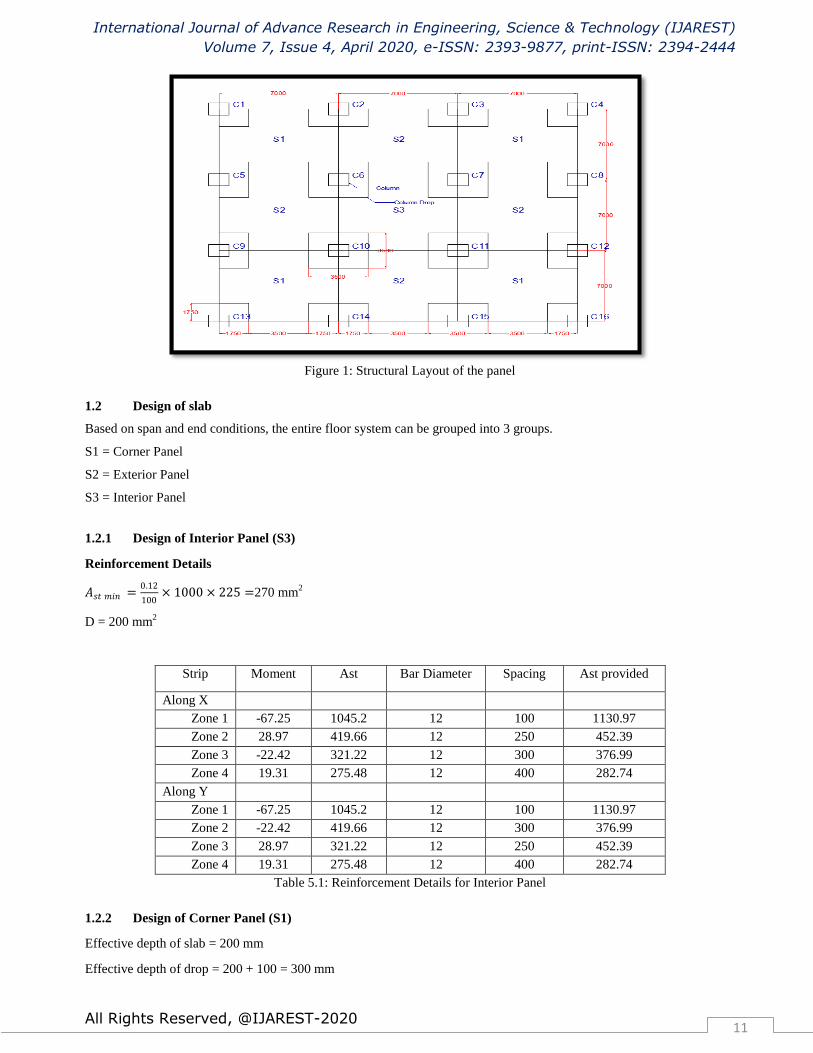
Figure 1: Structural Layout of the panel
1.2 Design of slab
Based on span and end conditions, the entire floor system can be grouped into 3 groups.
S1 = Corner Panel
S2 = Exterior Panel
S3 = Interior Panel
1.2.1 Design of Interior Panel (S3)
Reinforcement Details
𝐴𝑠𝑡 𝑚𝑖𝑛 =0.12
100× 1000 × 225 =270 mm
2
D = 200 mm2
Strip Moment Ast Bar Diameter Spacing Ast provided
Along X
Zone 1 -67.25 1045.2 12 100 1130.97
Zone 2 28.97 419.66 12 250 452.39
Zone 3 -22.42 321.22 12 300 376.99
Zone 4 19.31 275.48 12 400 282.74
Along Y
Zone 1 -67.25 1045.2 12 100 1130.97
Zone 2 -22.42 419.66 12 300 376.99
Zone 3 28.97 321.22 12 250 452.39
Zone 4 19.31 275.48 12 400 282.74
Table 5.1: Reinforcement Details for Interior Panel
1.2.2 Design of Corner Panel (S1)
Effective depth of slab = 200 mm
Effective depth of drop = 200 + 100 = 300 mm

International Journal of Advance Research in Engineering, Science & Technology (IJAREST)
Volume 7, Issue 4, April 2020, e-ISSN: 2393-9877, print-ISSN: 2394-2444
All Rights Reserved, @IJAREST-2020 12
Reinforcement Details
Strip Moment Ast Bar Diameter Spacing Ast provided
Along X
Zone 1 (exterior) -26.07 375.89 12 300 376.99
Zone 1 (interior) -72.59 1140.78 12 90 1256.63
Zone 2 40.92 604.91 12 180 628.31
Zone 3 (interior) -24.19 347.80 12 300 376.99
Zone 4 27.27 394.07 12 280 403.91
Along Y
Zone 1 (exterior) -26.07 375.89 12 300 376.99
Zone 1 (interior) -72.59 1140.78 12 90 1256.63
Zone 2 (interior) -24.19 347.80 12 300 376.99
Zone 3 40.92 604.91 12 180 628.31
Zone 4 27.27 394.07 12 300 403.91
Table 5.2: Reinforcement Details for Corner Panel
1.2.3 Design of Exterior Panel (S2)
Reinforcement Details
Strip Moment Ast Bar Diameter Spacing Ast provided
Along X
Zone 1 (exterior) -38.63 568.87 12 180 628.31
Zone 1 (interior) -71.66 1123.94 12 100 1130.97
Zone 2 38.83 572.03 12 180 628.31
Zone 3 (interior) -23.88 343.17 12 300 376.99
Zone 4 25.89 373.17 12 300 376.99
Along Y
Zone 1 (exterior) -38.63 568.87 12 180 628.31
Zone 1 (interior) -71.66 1123.94 12 100 1130.973
Zone 2 (interior) -23.88 343.17 12 300 376.99
Zone 3 38.83 572.03 12 180 628.31
Zone 4 25.89 373.17 12 300 376.991
Table 5.3: Reinforcement Details for Exterior Panel
VI. ESTIMATION AND COSTING
6.1 Estimating the quantities of various items of work
6.1.1 Quantity of Concrete:
Volume of Concrete = L x B x H = 21 x 21 x 0.225 = 99.225 m3
Volume of bubble = 0.52 × 0.52 × 0.178 = 0.0481 m3
For 1296 bubble Volume = 62.33 m3
Volume of Drop panel = 3.5 x 3.5 x 0.1 = 1.225 m3
Volume of Concrete required = 99.225 – 62.33 +1.225 = 38.12 m3
6.1.2 Shuttering:
Shuttering=21 x 21
= 441 m2
International Journal of Advance Research in Engineering, Science & Technology (IJAREST)
Volume 7, Issue 4, April 2020, e-ISSN: 2393-9877, print-ISSN: 2394-2444
All Rights Reserved, @IJAREST-2020 13
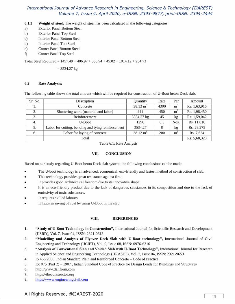
6.1.3 Weight of steel: The weight of steel has been calculated in the following categories:
a) Exterior Panel Bottom Steel
b) Exterior Panel Top Steel
c) Interior Panel Bottom Steel
d) Interior Panel Top Steel
e) Corner Panel Bottom Steel
f) Corner Panel Top Steel
Total Steel Required = 1457.49 + 406.97 + 355.94 + 45.02 + 1014.12 + 254.73
= 3534.27 kg
6.2 Rate Analysis:
The following table shows the total amount which will be required for construction of U-Boot beton Deck slab.
Sr. No. Description Quantity Rate Per Amount
1. Concrete 38.12 m3 4300 m
3 Rs. 1,63,916
2. Shuttering work (material and labor) 441 450 m2 Rs. 1,98,450
3. Reinforcement 3534.27 kg 45 kg Rs. 1,59,042
4. U-Boot 1296 8.5 Nos. Rs. 11,016
5. Labor for cutting, bending and tying reinforcement 3534.27 8 kg Rs. 28,275
6. Labor for laying of concrete 38.12 m3 200 m
3 Rs. 7,624
Total Rs. 5,68,323
Table 6.1: Rate Analysis
VII. CONCLUSION
Based on our study regarding U-Boot beton Deck slab system, the following conclusions can be made:
The U-boot technology is an advanced, economical, eco-friendly and fastest method of construction of slab.
This technology provides great resistance against fire.
It provides good architectural freedom due to its innovative shape.
It is an eco-friendly product due to the lack of dangerous substances in its composition and due to the lack of
emissivity of toxic substances.
It requires skilled labours.
It helps in saving of cost by using U-Boot in the slab.
VIII. REFERENCES
1. “Study of U-Boot Technology in Construction”, International Journal for Scientific Research and Development
(IJSRD), Vol. 7, Issue 04, ISSN: 2321-0613
2. “Modelling and Analysis of Flyover Deck Slab with U-Boot technology”, International Journal of Civil
Engineering and Technology (IJCIET), Vol. 9, Issue 08, ISSN: 0976-6316
3. “Analysis of Conventional Slab and Voided Slab with U-Boot Technology”, International Journal for Research
in Applied Science and Engineering Technology (IJRASET), Vol. 7, Issue 04, ISSN: 2321-9653
4. IS 456:2000, Indian Standard Plain and Reinforced Concrete – Code of Practice
5. IS: 875 (Part 2) – 1987 , Indian Standard Code of Practice for Design Loads for Buildings and Structures
6. http://www.daliform.com
7. https://theconstructor.org
8. https://www.engineeringcivil.com