design of intake systems for better in-cylinder turbulent flow p m v subbarao professor mechanical...
TRANSCRIPT
Design of Intake Systems for better in-cylinder Turbulent Flow
P M V SubbaraoProfessor
Mechanical Engineering Department
Introduce and Control Organized Turbulence …..
A Task unlikely to be completed in the near future ?!?!
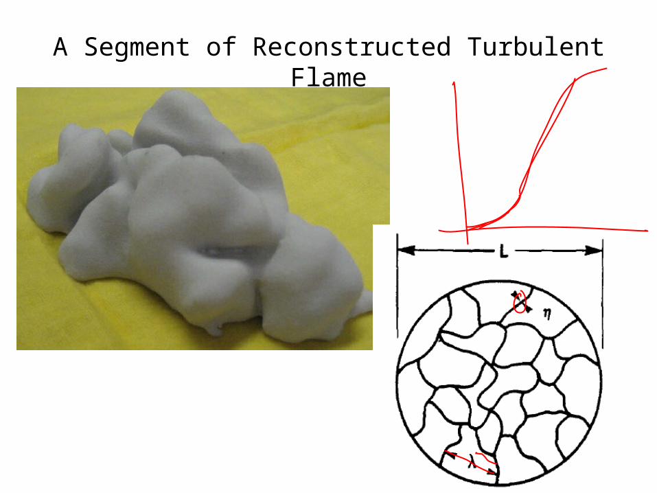
A Segment of Reconstructed Turbulent Flame

Influence of turbulent scale & Intensity on minimum ignitionenergy
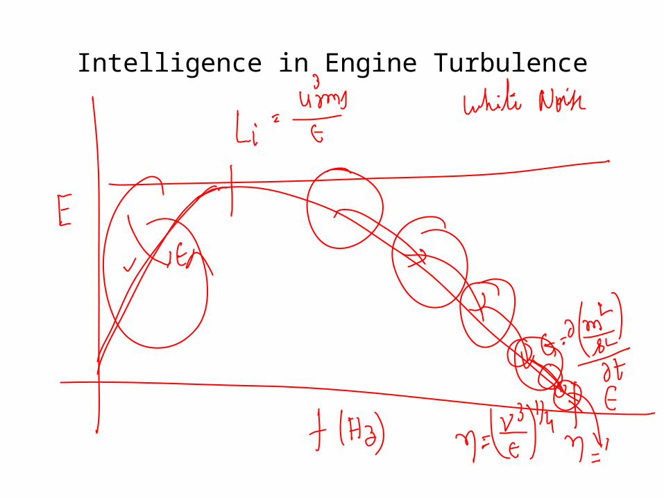
Intelligence in Engine Turbulence

Large Scales: Parents Vortices

Quick Combustion with Fuel Economy
• To promote quick combustion, sufficient large-scale turbulence is needed at the end of the compression stroke.
• Large scales of turbulence will result in a better mixing process of air and fuel and it will also enhance flame development.
• Too much turbulence leads to excessive heat transfer from the gases to the cylinder walls, and may create problems of flame propagation .
• The key to efficient combustion is to have enough turbulence in the combustion chamber prior to ignition.
• This turbulence can be created by the design of the intake port

Schematic diagram of the experimental setup

Types of Intake Flows• There are two types of structural turbulence that are
recognizable in an engine; tumbling and swirl.
• Both are created during the intake stroke.
• Tumble is defined as the in-cylinder flow that is rotating around an axis perpendicular with the cylinder axis.
Swirl is defined as the charge that rotates concentrically about the axis of the cylinder.
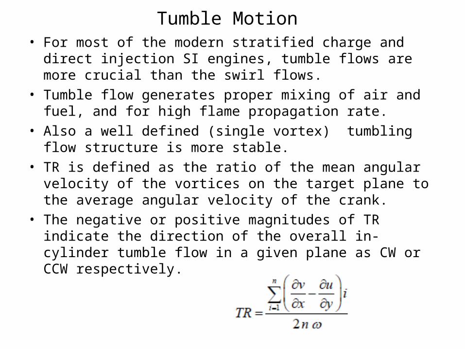
Tumble Motion • For most of the modern stratified charge and direct injection
SI engines, tumble flows are more crucial than the swirl flows.
• Tumble flow generates proper mixing of air and fuel, and for high flame propagation rate.
• Also a well defined (single vortex) tumbling flow structure is more stable.
• TR is defined as the ratio of the mean angular velocity of the vortices on the target plane to the average angular velocity of the crank.
• The negative or positive magnitudes of TR indicate the direction of the overall in-cylinder tumble flow in a given plane as CW or CCW respectively.
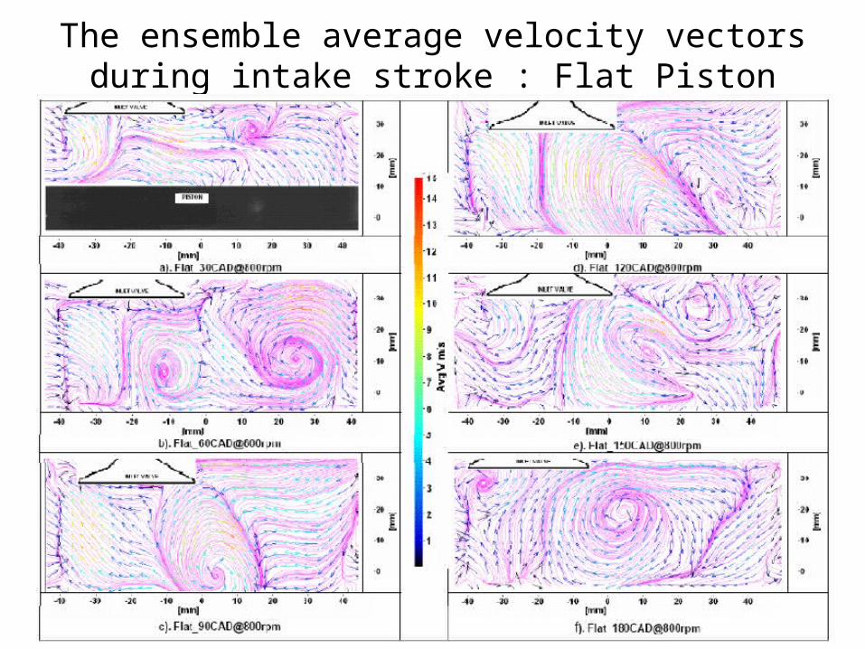
The ensemble average velocity vectors during intake stroke : Flat Piston
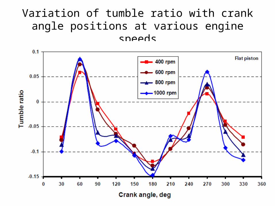
Variation of tumble ratio with crank angle positions at various engine speeds
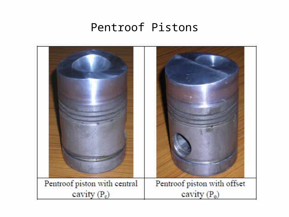
Pentroof Pistons
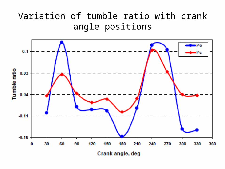
Variation of tumble ratio with crank angle positions

Valve Geometry Vs Turbulence

Control of Turbulence Level
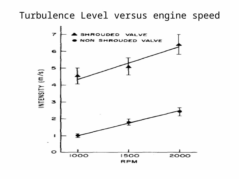
Turbulence Level versus engine speed

Control of Integral Scale

Integral Scale Vs Speed

Variation of turbulent intensity with volumetric

Tumble based Injection systems
P M V SubbaraoMechanical Engineering,IIT Delhi
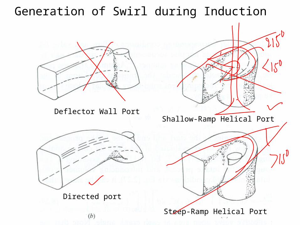
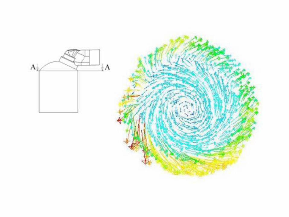
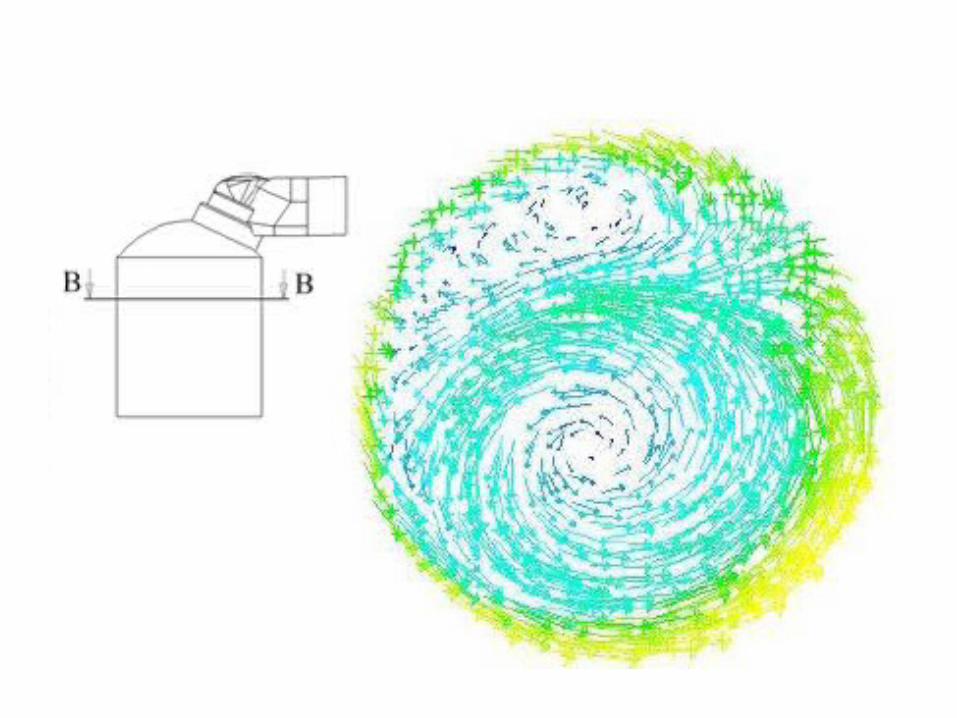
Generation of Swirl during Induction
Deflector Wall Port
Directed port
Shallow-Ramp Helical Port
Steep-Ramp Helical Port

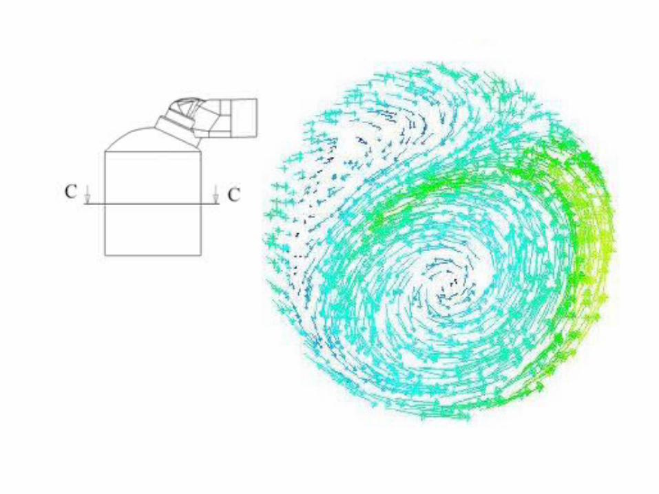


Measures of Swirl
• Two different values are calculated to assess the swirl intensity.
• Swirl number or swirl coefficient and swirl component or swirl number.
• The first, the swirl number, is the ratio of angular momentum to the axial momentum:
This angular momentum is calculated in the centre of the swirl (not on the cylinder axis).
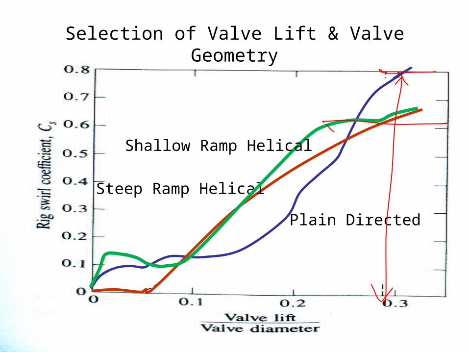
Selection of Valve Lift & Valve Geometry
Plain Directed
Steep Ramp Helical
Shallow Ramp Helical
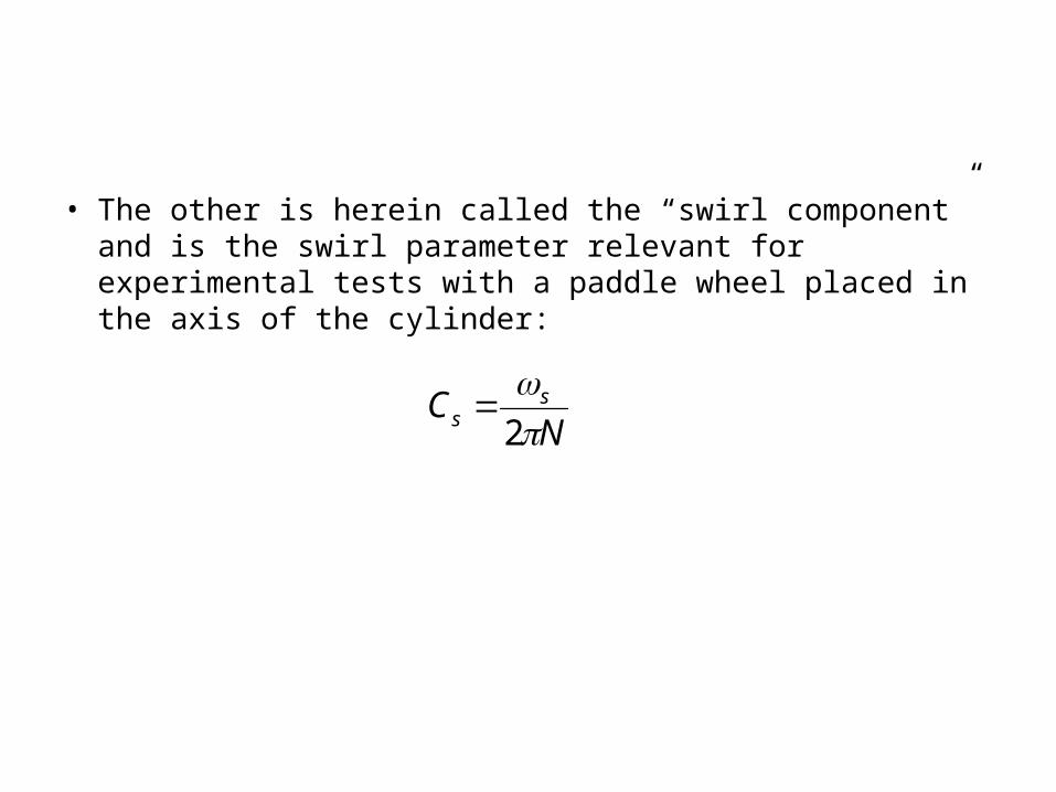
• The other is herein called the “swirl component” and is the swirl parameter relevant for experimental tests with a paddle wheel placed in the axis of the cylinder:
NC ss
2
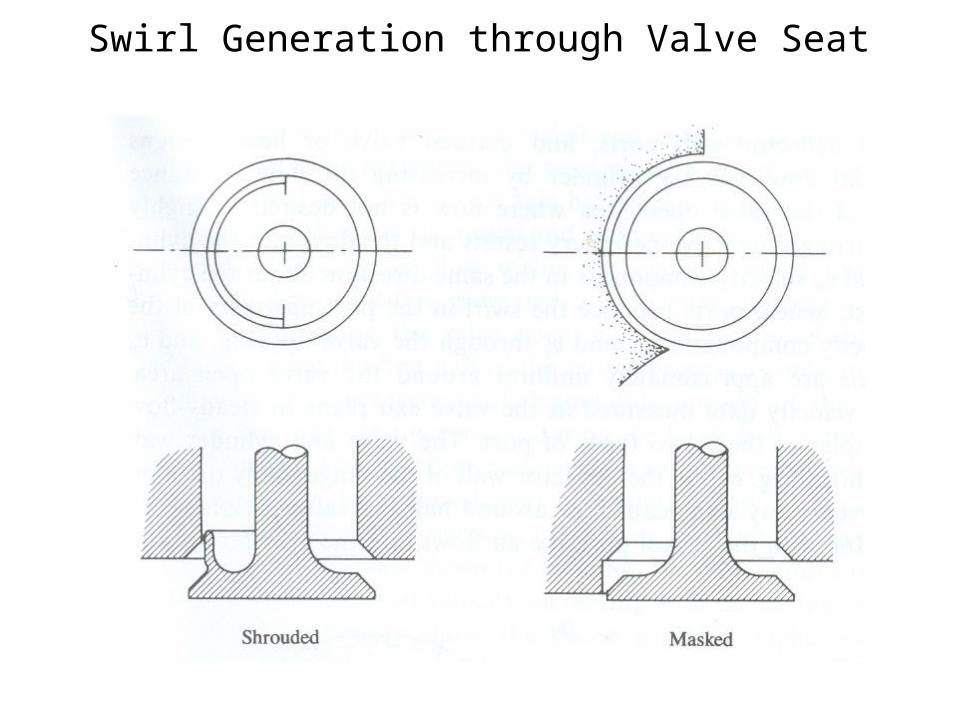
Swirl Generation through Valve Seat

Pistons for Swirl based systems