design of an experimental setup for hydro-kinetic energy conversion
TRANSCRIPT
http://uu.diva-portal.org This paper has been published in The International Journal on Hydropower & Dams and is made available in DiVA with permission from Hydropower & Dams Aqua-Media International. Citation: M. Grabbe, K. Yuen, A. Goude, E. Lalander and M. Leijon "Design of an experimental setup for hydro-kinetic energy conversion" The International Journal on Hydropower & Dams, 2009, Vol. 16, Issue 5, pp. 112-116 URL: http://www.hydropower-dams.com/
The kinetic energy of water currents could makea significant contribution to global electricityproduction, provided suitable technical solu-
tions are developed. As reported in the last issue ofH&D [Acker, 20091], research and development in themarine and tidal current energy sector is becomingmore intense and several projects are reaching thefinal stages of their first full-scale demonstration facil-ities. There are also projects looking at utilizing thekinetic energy in rivers [Khan, Iqbal and Quaicoe,20082].
Many tidal turbine designs, for example the 1.2 MWSeaGen deployed in Strangford Lough, NorthernIreland, by Marine Current Turbines [Fraenkel, 20073]and the Free Flow System turbine deployed in NewYork City’s East River by Verdant Power, resemblestout, submerged wind powerplants, which seems areasonable starting point for exploiting the kineticenergy of a fluid with a density 800 times higher thanthat of air. At the same time, strong efforts are beingmade to find other turbine concepts suitable for hydro-kinetic energy conversion. More than one-third of the76 tidal technologies surveyed by Khan et al [20094],are vertical axis (cross-flow) turbines.
Research in the area of marine current energy hasbeen underway at Uppsala University since 2000. It isbelieved that the functionality and survivability of amarine energy system demands simplicity and robust-ness. Thus, the focus has been on the development of asystem with few moving parts, to limit the need for
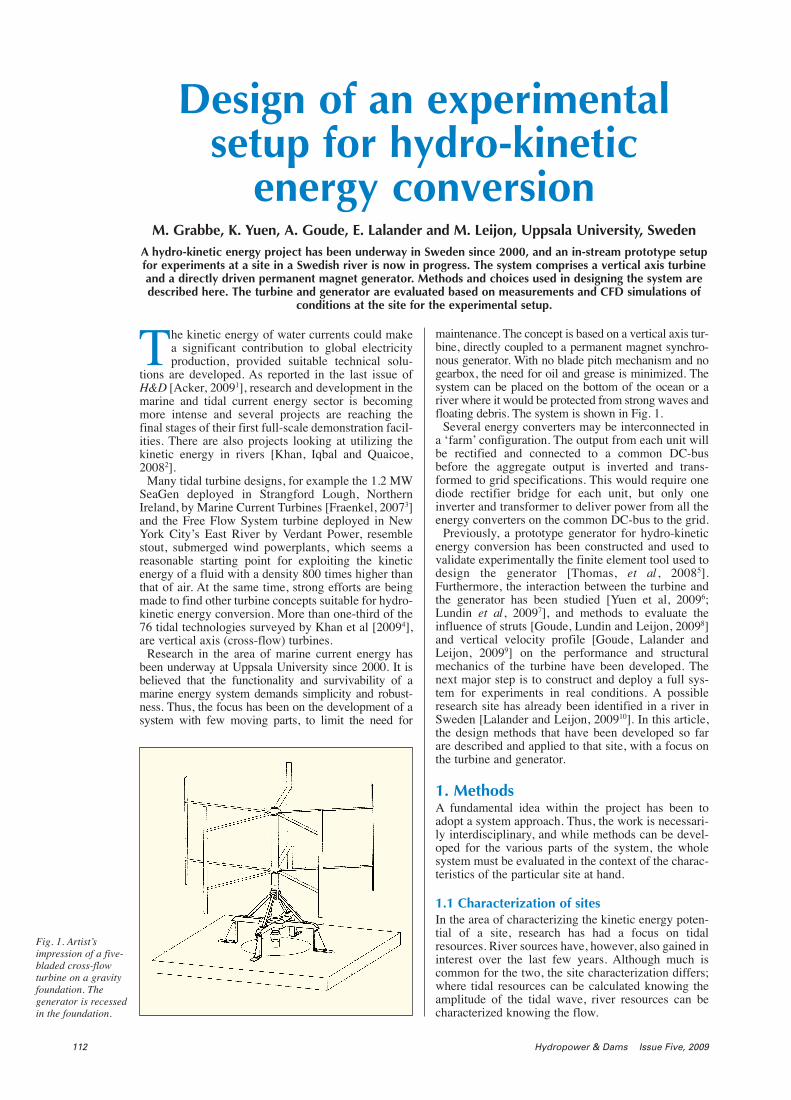
maintenance. The concept is based on a vertical axis tur-bine, directly coupled to a permanent magnet synchro-nous generator. With no blade pitch mechanism and nogearbox, the need for oil and grease is minimized. Thesystem can be placed on the bottom of the ocean or ariver where it would be protected from strong waves andfloating debris. The system is shown in Fig. 1.
Several energy converters may be interconnected ina ‘farm’ configuration. The output from each unit willbe rectified and connected to a common DC-busbefore the aggregate output is inverted and trans-formed to grid specifications. This would require onediode rectifier bridge for each unit, but only oneinverter and transformer to deliver power from all theenergy converters on the common DC-bus to the grid.
Previously, a prototype generator for hydro-kineticenergy conversion has been constructed and used tovalidate experimentally the finite element tool used todesign the generator [Thomas, et al , 20085].Furthermore, the interaction between the turbine andthe generator has been studied [Yuen et al, 20096;Lundin et al, 20097], and methods to evaluate theinfluence of struts [Goude, Lundin and Leijon, 20098]and vertical velocity profile [Goude, Lalander andLeijon, 20099] on the performance and structuralmechanics of the turbine have been developed. Thenext major step is to construct and deploy a full sys-tem for experiments in real conditions. A possibleresearch site has already been identified in a river inSweden [Lalander and Leijon, 200910]. In this article,the design methods that have been developed so farare described and applied to that site, with a focus onthe turbine and generator.
1. MethodsA fundamental idea within the project has been toadopt a system approach. Thus, the work is necessari-ly interdisciplinary, and while methods can be devel-oped for the various parts of the system, the wholesystem must be evaluated in the context of the charac-teristics of the particular site at hand.
1.1 Characterization of sitesIn the area of characterizing the kinetic energy poten-tial of a site, research has had a focus on tidalresources. River sources have, however, also gained ininterest over the last few years. Although much iscommon for the two, the site characterization differs;where tidal resources can be calculated knowing theamplitude of the tidal wave, river resources can becharacterized knowing the flow.
112 Hydropower & Dams Issue Five, 2009
Design of an experimentalsetup for hydro-kinetic
energy conversionM. Grabbe, K. Yuen, A. Goude, E. Lalander and M. Leijon, Uppsala University, Sweden
A hydro-kinetic energy project has been underway in Sweden since 2000, and an in-stream prototype setupfor experiments at a site in a Swedish river is now in progress. The system comprises a vertical axis turbineand a directly driven permanent magnet generator. Methods and choices used in designing the system aredescribed here. The turbine and generator are evaluated based on measurements and CFD simulations of
conditions at the site for the experimental setup.
Fig. 1. Artist’simpression of a five-bladed cross-flowturbine on a gravityfoundation. Thegenerator is recessedin the foundation.

Water current measurements are often scarce, espe-cially measurements made specifically for character-izing the hydro-kinetic potential of a site. Surfaceobservations for navigational purposes and river dis-charge data are more common, but the accuracy andstringency of such data are often not sufficient to carryout a reliable resource assessment.
The variation of current speed along a channel canbe obtained using numerical models with flow dataand high-resolution bathymetry data as input. In theproject at Uppsala University, a two-dimensionalhydrodynamic model (Mike21 Flow model FM) isused for this purpose. The model is capable of calcu-lating the velocity and water depth along the entirechannel. With the use of the model, the effects andpower output of turbines can also be estimated[Lalander and Leijon, 200910].
1.2 Turbine design and modellingDesign and modelling of vertical axis turbines is acomplex task where the engineer is faced with manydesign choices which will affect the turbine perfor-mance and structural strength. A number of authorshave presented numerical models of vertical axis tur-bines, but it appears that there is a lack of experimen-tal data for comparison and validation of the models.Pioneering work in offshore experiments with verticalaxis turbines has been carried out in Italy [Coiro et al,200511] and Japan [Kiho, Shiono and Suzuki, 199612],but it would still be desirable to have more detaileddata of the forces and moments on each blade.
In this study, a double multiple streamtube model[Paraschivoiu and Delclaux, 198313; Paraschivoiu,200214] is implemented for turbine design. The modelis based on experimental data for lift and drag coeffi-cients obtained from Sheldahl and Klimas [198115].Tip corrections resulting from a finite aspect ratio aremade, as described by Paraschivoiu [200214].Dynamic stall is modelled using the Gormont method[Gormont, 197316] with the modifications of Massé[198117] and Berg [198318]. To incorporate the dynam-ic stall model with the finite aspect ratio corrections,dynamic stall is calculated on the reduced angle ofattack obtained by the tip corrections, and the induceddrag is recalculated with the new value of the lift coef-ficient. Corrections to take into account the effect ofstruts are made, using the method described byGoude, Lundin and Leijon [20098], and the verticalvelocity profile was included using the method ofGoude, Lalander and Leijon [20099]; however theexpansion model was not taken into account, to makethe model compatible with the strut corrections.
1.3 Generator design and modellingToday, design tools based on the finite elementmethod are standard for modelling rotating electricalmachines. The cable-wound permanent magnet gener-ators presented here are modelled using an in-houseFEM software based on the program ACE [200119]. Arecently calculated machine designed for 5 kW, 10rpm, and with 120 poles has shown good correlationwith experimental results [Thomas, et al, 20085].
A generator designed for this application is moststrongly characterized by low rotation speeds, in theorder of 10 rpm, and a wide operating range in terms ofspeed and power. The design point has been a typicaloperation point rather than the upper limit that the term‘rated power’ tends to denote. A low current density anda low load angle have been sought at the design point,allowing for high over-loads. As the velocity of the
water current changes, the rotation speed should bechanged proportionally, so as to maintain approximate-ly the same tip-speed ratio. At the same time, the powerabsorbed by the turbine will change proportionally tothe cube of the water velocity.
It should be recognized that maximizing the powerabsorption of the turbine is not necessarily the samething as maximizing the power output of the wholesystem, nor is it the same thing as minimizing cost perkWh produced. It is, however, a reasonable guide indesigning the generator. Depending on site-specificconditions and other design constraints, one may optto limit the power absorption at higher velocities, toachieve a high degree of utilization [Clarke et al, 200620]. Such an approach could have a strong impact onthe economic feasibility of any renewable energy pro-ject [Leijon et al, 200321].
2. Experimental setupA site was chosen where a full-system experimentalsetup could be deployed, including a turbine, genera-tor, and necessary power electronics for control andpower conversion to grid specifications. The purposeof this is to prove the concept, to validate simulations,and to learn more about the conditions for and charac-teristics of this type of energy conversion system.
An ideal site for research may differ from a site forcommercial electricity production, as the purpose ofan experimental setup is to take measurements undervarious conditions rather than to produce electricity ata competitive price. Guidelines in finding a site havebeen related to issues such as variations in currentvelocity, depth and width of the waterway, but alsopractical issues such as proximity to the university,other uses of the water, and availability of a site for amonitoring station on land.
2.1 Söderfors in the Dal riverThe kinetic energy potential of the Dal river has beenstudied. Close to its outlet in the sea, about 1 kmdownstream of a hydropower station in the town ofSöderfors, a suitable site has been identified, see Fig.2 and the photo on p114. The channel is about 100 mwide at the site with a depth of 6 to 7 m. Current mea-surements and water depth readings at the site weremade using a 1200 kHz ADCP from RD Instrumentsover a 30 day period and compared with hourly flowdata from the upstream hydropower plant. A linearrelationship between velocity and flow was thenobtained.
Hydropower & Dams Issue Five, 2009 113
Fig. 2. The channeldownstream fromthe Söderfors hydroplant. The velocitydata have beengenerated usingMike21.

This linear relationship was used to extrapolatevelocity data for a wide range of flows. By using dis-charge data from between 2004 and 2008, the veloci-ty distribution for five years at the chosen site could befound. The annual velocity distribution, averaged overthe five years, is shown in Fig. 3. As the Figure shows,the velocity is mostly within 0.4 and 1.4 m/s. For tur-bine simulations, a vertical profile was required. Thiswas obtained by averaging a velocity sample over 24hours. The resulting vertical profile is shown in Fig. 4.
2.2 Turbine for experimental setupThe first constraint for the turbine is the available depthat the considered site. A five-bladed turbine with a heightof 3.5 m and a 3 m radius was considered suitable, leav-ing ample clearance from the bottom and the surface.The number of blades and solidity affects various issuessuch as blade chord length, and thus the structuralintegrity of the blades and the weight of the machine.
The turbine (blade profile NACA0021, 0.18 m chord)was simulated according to section 3.2 for water veloc-ities of 0.4 to 1.5 m/s. The simulated power coefficient,Cp, in Fig. 5 was calculated using the measured veloc-ity profile in Fig. 4, where the turbine was assumed tobe located between 1 m and 4.5 m below the surface.The value was normalized against the incoming ener-gy of the flow, which was obtained by integrating theincoming velocity profile over the turbine area.
The variations in maximum Cp caused by flowvelocity, as seen in Fig. 6, were calculated with homo-geneous velocity profiles as the velocity profile onlyhad a small impact on the turbine performance.However, the method developed to take the velocityprofile into account [Goude, Lalander and Leijon,20099] is of importance when considering the load dis-tribution and structural mechanics of the turbine. Thedecrease in maximum Cp at low velocities can beexplained by a decrease in the Reynolds number of thesystem, which increases the drag coefficient and low-ers the stall angle.
2.3 Generator for experimental setup in SöderforsThe site and turbine described above are fairly well
114 Hydropower & Dams Issue Five, 2009
Fig. 5. Cp versus tip-speed ratio for the selected turbine, usingthe velocity profile in Fig. 4. Strut losses are included. Amaximum Cp value of 0.35 is obtained at tip-speed ratio 3.5.
View of the site atSöderfors.
Fig. 3. Annualwater speeddistribution atthe selected site,averaged overfive years.
Fig. 4. Velocityprofile at theselected site: 24 haverage.
Fig. 6. Maximum Cp for the selected turbine at different watercurrent velocities.
matched by the prototype generator used by Yuen et al[20096]. However, the generator was slightlyredesigned to make better use of the low velocitiesavailable in Söderfors.
As discussed by Yuen et al [20096], iron losses dom-inate at lower speeds, and these iron losses are propor-tional to the volume of iron in the stator. The amountof iron in the stator can be reduced (while maintainingthe frequency) by, for example, making a shortermachine. As a result, however, this will also reduce thevoltage. A lower voltage results in a higher current fora given speed and power, thus resulting in higher cop-per losses at higher water current speeds. Table 1shows the length and voltage at 5 rpm for three gener-ators with a cross-sectional geometry based on that ofthe prototype in the paper by Yuen et al. Details of thegenerators are shown in Table 2. The generators aresimulated with a purely resistive load and frictionallosses in bearings are not considered at this point.
3. ResultsIn Fig. 7, the maximum power absorption of the tur-bine has been matched with the operation of the gener-ators at different current velocities. We can see thatgenerator A has a better efficiency at low speeds, whilegenerator C has a better efficiency at high speeds.
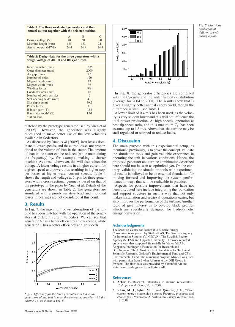
In Fig. 8, the generator efficiencies are combinedwith the Cp-curve and the water velocity distribution(average for 2004 to 2008). The results show that Bgives a slightly better annual energy yield, though thedifference is small, see Table 1.
A lower limit of 0.4 m/s has been used, as the veloc-ity is very seldom lower and this will not influence thetotal power production. At high speeds, operation atbest tip-speed ratio, and thus maximum Cp, has beenassumed up to 1.5 m/s. Above that, the turbine may bestall-regulated or stopped to reduce loads.
4. DiscussionThe main purpose with this experimental setup, asmentioned previously, is to prove the concept, validatethe simulation tools and gain valuable experience inoperating the unit in various conditions. Hence, theproposed generator and turbine combination describedhere should not be seen as optimized yet. On the con-trary, validating the simulation tools with experimen-tal results is believed to be an essential foundation formoving forward and improving the system perfor-mance in ways that will be realizable in practice.
Aspects for possible improvements that have notbeen discussed here include integrating the foundationand support structure in such a way that not onlymakes installation and retrieval operations easier, butalso improves the performance of the turbine. Anothertopic of great interest is to develop blade profileswhich are specifically designed for hydro-kineticenergy conversion. ◊
AcknowledgmentsThe Swedish Centre for Renewable Electric EnergyConversion is supported by Statkraft AS, The Swedish Agencyfor Innovation Systems (VINNOVA), The Swedish EnergyAgency (STEM) and Uppsala University. The work reportedon here was also supported financially by Vattenfall AB,Ångpanneföreningen’s Foundation for Research andDevelopment, The J. Gust. Richert Foundation for TechnicalScientific Research, Östkraft’s Environmental Fund and CF’sEnvironmental Fund. The numerical program Mike21 was usedwith permission from Stefan Ahlman at the DHI Group inSweden. The flow data was provided by Vattenfall AB andwater level readings are from Fortum AB.
References1. Acker, F.,”Research intensifies in marine renewables”.
Hydropower & Dams, No. 4, 2009.
2. Khan, M. J., Iqbal, M. T. and Quaicoe, J. E., “Rivercurrent energy conversion system: Progress, prospects andchallenges”, Renewable & Sustainable Energy Reviews, No.12, 2008.
Hydropower & Dams Issue Five, 2009 115
Table 1: The three evaluated generators and theirannual output together with the selected turbine.
A B CDesign voltage (V) 40 60 80Machine length (mm) 125 183 241Annual output (MWh) 24.4 24.9 24.4
Table 2: Design data for the three generators with adesign voltage of 40, 60 and 80 V,at 5 rpm.
Inner diameter (mm) 1835Outer diameter (mm) 2000Air gap (mm) 7.5Number of poles 120Magnet height (mm) 13Magnet width (mm) 36Winding factor 9/8Conductor area (mm2) 16Number of coils per slot 6Slot opening width (mm) 4.0Slot depth (mm) 59.2Power factor 1.0B in air gap* (T) 0.84B in stator tooth* (T) 1.64* at no-load
Fig. 8. Electricityproduction atdifferent speedsduring a year.
Fig. 7. Efficiency for the three generators: in black, thegenerators alone; and in grey, the generators together with theturbine Cp, as shown in Fig. 6.

3. Fraenkel, P. L., ”Marine current turbines: Moving fromexperimental test rigs to a commercial technology”. In:Proceedings, 26th International Conference on OffshoreMechanics and Arctic Engineering, June 2007.
4. Khan, M. J., Bhuyan, G., Iqbal, M. T., and Quaicoe, J. E.,“Hydrokinetic energy conversion systems and assessment ofhorizontal and vertical axis turbines for river and tidalapplications: A technology status review”, Applied Energy,Vol. 86, No. 10, October 2009.
5. Thomas, K., Grabbe, M., Yuen, K. and Leijon, M., “Alow speed generator for energy conversion from marinecurrents - experimental validation of simulations”.Proceedings, IMechE Part A: Journal of Power and Energy,Vol. 222, No. 4, 2008.
6. Yuen, K. Thomas, K. Grabbe, M. Deglaire, P. Bouquerel,M. Österberg, D. and Leijon. M., “Matching a permanentmagnet synchronous generator to a fixed pitch vertical axisturbine for marine current energy conversion”, IEEE Journalof Oceanic Engineering, Vol. 34 No. 1, 2009.
7. Lundin, S., Grabbe, M., Yuen, K. and Leijon. M., “Adesign study of marine current turbine-generatorcombinations”, Proceedings, 28th International Conferenceon Offshore Mechanics and Arctic Engineering, 2009.
8. Goude, A., Lundin, S. and Leijon M., “A parameter studyof the influence of struts on the performance of a vertical-axis marine current turbine”. Proceedings, 8th Europeanwave and tidal energy conference, Uppsala, Sweden; 2009.
9. Goude, A., Lalander, E. and Leijon M., “Influence of avarying vertical velocity profile on turbine efficiency for avertical axis marine current turbine, Proceedings, 28thInternational Conference on Offshore Mechanics and ArcticEngineering; 2009.
10. Lalander E. and Leijon M., “Numerical modelling of ariver site for in-stream energy converters”. Proceedings, 8thEuropean wave and tidal energy conference, Uppsala,Sweden; 2009.
11. Coiro, D. P., De Marco, A., Nicolosi, F., Melone, S. andMontella, F., “Dynamic behaviour of the patented Koboldtidal turbine: numerical and experimental aspects”, ActaPolytechnica, Vol. 45, No. 3, 2005.
12. Kiho, S., Shiono, M. and Suzuki. K., “The powergeneration from tidal currents by a Darrieus turbine, Worldrenewable energy congress on renewable energy, energyefficiency and the environment; Vol. 2, 1996.
13. Paraschivoiu, I. and Delclaux, F., ”Double-multiplestreamtube model with recent improvements”, Journal ofEnergy; Vol. 7,May-June 1983.
14. Paraschivoiu, I., “Wind turbine design with emphasis onDarrieus concept,” Polytechnic International Press; 2002.
15. Sheldahl, R. E. and Klimas, P. C., “Aerodynamiccharacteristics of seven symmetrical airfoil sections through180-degree angle of attack for use in aerodynamic analysisof vertical axis wind turbines,” Technical Report SAND80-2114, Sandia National Laboratories, Albuquerque, NewMexico, USA; March 1981.
16. Gormont, R. E., “A mathematical model of unsteadyaerodynamics and radial flow for application to helicopterrotors”, Technical report, USAAV Labs.; May 1973.
17. Massé, B., “Description de deux programmes d’ordinateurpour le calcul des performances et des chargesaerodynamiques pour des eoliennes a’axe vertical,” ReportIREQ 2379, Institut de Recherche de l’Hydro–Quebec,Quebec, Canada; July 1981.
18. Berg, D. E., “An improved double-multiple streamtubemodel for the Darrieus type vertical-axis wind turbine,”Proceedings, Sixth biennial wind energy conference andworkshop, Minneapolis, MN, USA; June 1983.
19. ACE, User manual, modified version 3.1, ABB commonplatform for field analysis and simulations. ABB CorporateResearch Centre, ABB AB Västerås, Sweden; 2001.
20. Clarke, J. A., Connor, G., Grant, A. D. and Johnstone C.M., “Regulating the output characteristics of tidal currentpower stations to facilitate better base load matching overthe lunar cycle”, Renewable Energy, Vol. 31, 2006.
21. Leijon, M., Bernhoff, H., Berg, M. and Ågren O.,“Economical considerations of renewable electric energyproduction - especially development of wave energy,”Renewable Energy, Vol. 28, 2003.
116 Hydropower & Dams Issue Five, 2009
A. Goude E. Lalander
K. Yuen
M. Leijon
M. Grabbe
M. Grabbe was awarded his MSc degree in EngineeringPhysics at Uppsala University, Sweden, in 2006. He iscurrently working towards a PhD in the field of tidal energy atthe Division of Electricity at Uppsala University.
K. Yuen was awarded her MSc in Engineering Physics atUppsala University, Sweden, in 2001. In 2006 she returned tothe University to work towards a PhD in renewable energyconversion.
A. Goude was also awarded his MSc in Engineering Physicsat Uppsala University, Sweden, in 2007. Currently, he isworking on his PhD with a focus on turbine simulation andmodelling.
E. Lalander obtained her MSc in Oceanography atGothenburg University, Sweden, in 2006. She is currentlyworking on her PhD in renewable energy conversion atUppsala University.
Prof. M. Leijon received his PhD in 1987 from ChalmersUniversity of Technology, Gothenburg, Sweden. From 1993 to2000, he was Head of the Department for High VoltageElectromagnetic Systems at ABB Corporate Research,Västerås, Sweden. In 2000 he became Professor of Electricityat Uppsala University, Sweden. He received the ‘John Ericssonmedal’ from Chalmers in 1984, the ‘Porjus International HydroPower Prize’ in 1998, the Royal University of Technology‘Grand Prize’ in 1998, the Finnish academy of science ‘WalterAlstrom prize’ in 1999, and the 2000 Chalmers ‘GustavDahlén medal’. He received both the Grand Energy Prize inSweden and the Polhem Prize in 2001 as well as the ThureusPrize 2003. He is a member of IEEE, IEE, WEC, CIGRE andthe Swedish Royal Academy of Engineering Science.
The Swedish Centre for Renewable Electric EnergyConversion, Department of Engineering Sciences, UppsalaUniversity, Box 534, SE-751 21, Uppsala, Sweden.