design of an efficient drying system · design of an efficient drying system ... develop a solution...
TRANSCRIPT

Design of an Efficient Drying System
Benjamin Kyle Dollins
Rebecca Leigh Hoey
Michael Ernest Matousek
Adviser: Dr. Paul Weckler
Technical Adviser: Dr. Tim Bowser
Prepared for S & S Farms
BAE 4023
Spring 2008

2
Table of Contents
Problem Introduction ........................................................................................................................................... 4
Previous Work ...................................................................................................................................................... 5
Patents ........................................................................................................................................................ 5
Sales Literature .......................................................................................................................................... 7
Research Articles ....................................................................................................................................... 9
Design Specifications ......................................................................................................................................... 12
Design Concepts ................................................................................................................................................. 12
Testing ................................................................................................................................................................ 17
Jerky Dehydrator ..................................................................................................................................... 17
Pepper Rehydration ................................................................................................................................. 18
Cabinet Dryer ........................................................................................................................................... 19
Capsaicin and Dicapsaicin Measurement............................................................................................... 20
Drying Rates ....................................................................................................................................................... 22
Moisture Content ..................................................................................................................................... 22
Drying Curve ............................................................................................................................................ 22
Estimated Drying Time ............................................................................................................................ 23
Design Parameters ............................................................................................................................................. 24
Flow rate .................................................................................................................................................. 24
Temperature ............................................................................................................................................. 24
Airflow ...................................................................................................................................................... 24
Layer Thickness ....................................................................................................................................... 24
Belt Area .................................................................................................................................................. 24
Air Velocity .............................................................................................................................................. 25
Retention Time ......................................................................................................................................... 25
Recommendations .............................................................................................................................................. 25
Layout....................................................................................................................................................... 25
Burners..................................................................................................................................................... 26
Fans .......................................................................................................................................................... 27
Conveyor .................................................................................................................................................. 27
Cost Analysis ...................................................................................................................................................... 28
Works Cited ........................................................................................................................................................ 29
Appendix A ......................................................................................................................................................... 31
Appendix B ......................................................................................................................................................... 40
Appendix C ......................................................................................................................................................... 42
Appendix D ......................................................................................................................................................... 47

3
Table of Figures
1.Peerless 103 Dual 3-Phase Dryer .........................................................................................7
2. GT Mfg. Inc. Grain Dryer ...................................................................................................8
3. DAIKA Model DDG 8000 ....................................................................................................8
4. Blue Peanut Dryer Model 2712 ...........................................................................................8
5. Dryer Set-up .........................................................................................................................10
6. Maxon NP-LE Airflo Burner ..............................................................................................13
7. Belt-o-matic Dryer................................................................................................................14
8. Jerky Dehydrator..................................................................................................................18
9. Cabinet Dryer. ......................................................................................................................19
10. Proctor Drying Tests .........................................................................................................20
11. Logarithmic plot of drying curve .......................................................................................22
12. Drying rates for different temperatures ............................................................................23
13. Recommended Dryer Layout .............................................................................................26
14. Maxon NP-LE Burner ......................................................................................................26
15. Hauck Mfg. Co Burner ......................................................................................................27
16. Grainger 42 inch tube axial fan ........................................................................................27
17. Cincinnati Fan 48 inch fan ...............................................................................................27
18. Wire mesh conveyor ..........................................................................................................27
Table of Tables
1. Summary of Air Energy Requirements ...............................................................................17
2. Proctor Dryer Setting ...........................................................................................................19
3. Chemical Measurements......................................................................................................21
4. Cost Summary of Components ............................................................................................28

4
Problem Introduction
Dean Smith, of S & S Farms in western Oklahoma, is a producer of super-hot chili
peppers for use in the pharmaceutical industry. His peppers are used for a variety of different
products, including Icy Hot and pepper spray. Before processing and shipping his peppers he
must reduce the moisture content to 5 %. The goal of Spicy Solutions is to develop a time and
cost effective drying method to reduce the expense associated with the increasing price of natural
gas, by developing a continuous flow drying process.
The current drying process consists of peanut wagons to hold the peppers, fifteen Peerless
103 dual 3-phase dryers that have natural gas burners to heat the air, and a blower that forces the
air into the false bottom of the peanut wagon. The peanut wagons are placed under open-sided
barns that are exposed to the environment. Currently the dryers raise the ambient air temperature
20°F (-6.7°C) to 30°F (-1.1°C). The current drying time for the peppers ranges from 48 hours at
the beginning of the drying season to about 18 hours at the end of the season. The peppers
remain in the field on the plant for as long as possible which allows them to dry naturally,
thereby reducing the additional energy required to dry them. After they are harvested, they are
stored in a barn until they are placed in the peanut wagons for drying. After the peppers have
been dried to the desired moisture, they are milled into a powder before being shipped off to the
extraction company.
For our project, the process must accommodate a total of 1,700,000 pounds (773,000 kg)
of peppers per year, and approximately 60,000 pounds per day (27,300 kg/day). A main
limitation of our project presented by the client is reducing the amount of natural gas used, which
will lower the cost of the process. The peppers also need to be processed in a timely manner to
maintain the speed of the milling process and reduce the chance of spoilage.

5
Spicy Solutions spent the spring semester performing calculations and running tests with
different conditions to determine the best design. At the conclusion of the year Spicy Solutions
would like to have a final design that is easy to implement and maintain. We would like to
develop a solution that would be easy to implement to reduce problems associated with the
incorporation of our solution. Reducing the maintenance will reduce the labor cost and the
possibility of slowing the process.
Previous Work
Patents
Spicy Solutions started researching patents to determine what was in use and if our design
ideas would infringe on existing patents. We found several patents on the topic, but none
presented much concern. Below is the team’s understanding of the patents that were found.
US Patent Application No. 20,070,160,729 Capsinoid-Containing Dried Chili Pepper Product
and Method of Drying the Same Date of Issue: July 12, 2007
The purpose of this patent is to discover suitable drying conditions that prevent the
decomposition of capsinoid compounds and increase the yield when drying capsinoid-containing
chili peppers. Another purpose is to maintain the stability of capsinoids during drying of chili
peppers. Chili peppers cut either before or during drying have increased surface area and
ruptured outer skin. These conditions accelerate the evaporation of internal moisture, enhance
drying efficiency and permit rapid drying. Frequent and uniform mixing and stirring causes
moisture to evaporate evenly from the peppers, thus preventing uneven heating. The patent
covers stirring at least once per hour. An air speed of 0.98 ft/s (0.3 m/s) or greater works well
for batch drying. An air speed of 0.66 ft/s (0.2 m/s) or greater works well for continuous drying.
An air temperature of 149°F (65°C) to 176°F (80°C) is used. The hot air is directed through the

6
bulk chili pepper material. These conditions prevent excessive heating of capsinoid and thus
suitably prevented it from decomposing.
The patent covers drying Manganji peppers, Shishito peppers, Fushimi Amanaga
peppers, and CH-19 Sweet peppers. It specifies that weight of peppers is reduced to less than
20% and the moisture content is reduced to less than 10% of the raw fruit. It covers the
following driers: band-type, fluidized bed-type, draft-type, rotating-type, spraying-type, stirring-
type, box-type, moving bed-type or drum-type. It further covers drying with a convective heat-
transfer dryer, using either continuous stirring or stirring at least once an hour.
U.S. Patent No. 7,137,580 System and method for pulverizing and extracting moisture
The patent covers an apparatus for pulverizing material and extracting moisture from
material. It is composed of an inlet tube, a venturi coupled to the inlet tube, an airflow generator
to generate airflow with an inlet aperture, an axel coupled to the airflow generator, a balancer
coupled to the axel to compensate for imbalance in the axel during rotation, and a housing at
least partially encompassing the airflow generator. An outlet communicates with the input
aperture, the airflow generator communicates with the venturi to direct the airflow through the
venturi, and toward the input aperture.
The material introduced into the airflow passes through the venturi and is subject to
pulverization and moisture extraction. A material flow rate is measured by an acoustic emission
sensor, which receives the resonant frequencies generated by the material passing through the
airflow generator. The material flow rate is measured to avoid overloading the system. This
patent is specific to the balancing apparatuses and methods for the rotating axel.
U.S. Patent No. 7,059,550 System and method for pulverizing and extracting moisture
7
This patent is relevant to the same system as the previous patent, U.S. Patent 7,137,580.
This patent is specific to the apparatuses that create, direct, and handle the air flow. It also
covers the heat generation, pulverizing system, and material feed equipment. It contains the
elaborate process of material flowing through the system. It also contains the communication
between components.
U.S. Patent No. 7,040,557 System and method for pulverizing and extracting moisture
This patent is relevant to the same system as the previous patent, U.S. Patent 7,137,580.
This patent is specific to the methods and apparatuses for the sensors, controllers, acoustic
emission sensor, and the communication between apparatuses.
Sales Literature
Market research was an important part of the team’s research. We were interesting in
determining what is available and if the client is using the best product. Listed below are the
results of our market research.
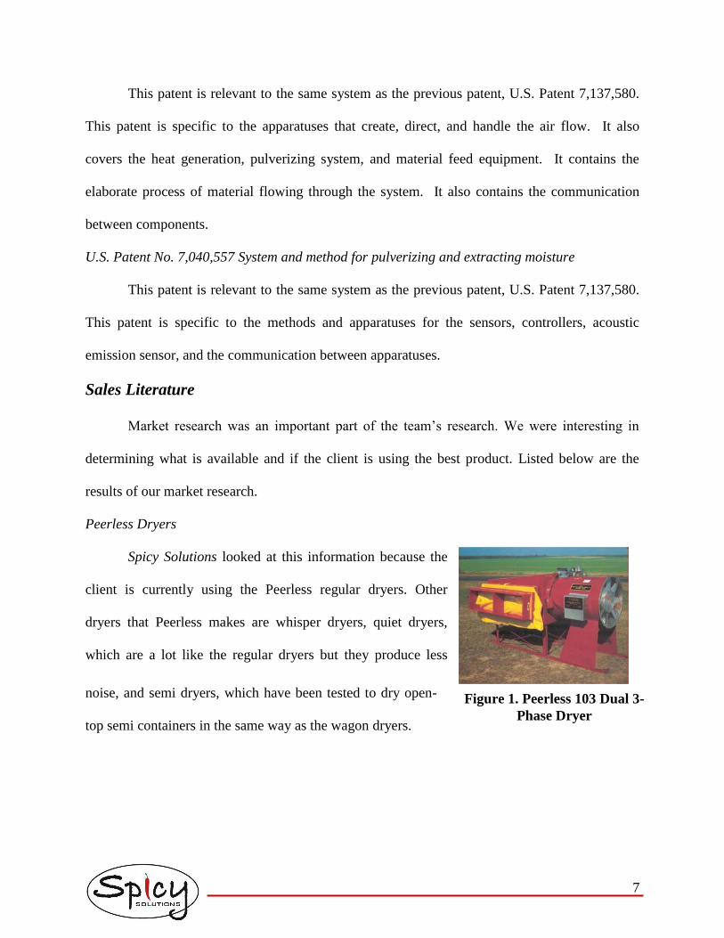
Peerless Dryers
Spicy Solutions looked at this information because the
client is currently using the Peerless regular dryers. Other
dryers that Peerless makes are whisper dryers, quiet dryers,
which are a lot like the regular dryers but they produce less
noise, and semi dryers, which have been tested to dry open-
top semi containers in the same way as the wagon dryers.
Figure 1. Peerless 103 Dual 3-
Phase Dryer

8
GT Mfg. Inc Grain Dryer Specs.
These dryers are recirculating batch grain dryers
that would not be feasible for our project because of the
set up of the dryers. They are geared more towards
small grains and would not be able to accommodate the
size of the chili peppers and the rate that they need to be
dried. They would not be easily incorporated into the
current process based on the way they hold the grain.
Peanut Dryers-Diaka Model DDG 8000
This dryer is typically used for drying peanuts and seeds. The dryer removes the humidity
out of the air and uses a heat pump cycle to generate drying heat. It is most efficient on summer
days, making it less feasible for our project since most
drying occurs in the middle of the winter. To supplement
the heat pump and increasing the temperature, it has a
LPG back-up burner attached that can be used during the
winter months. These dryers are not a feasible for this
project because they produce half of the volumetric flow
rate and horsepower.
Blueline Crop Dryers
These dryers are most often used to dry peanuts and they
are built to fit most standard peanut wagons. All Blueline Dryers
can be used with LP vapor or natural gas. They offer several
different models of dryers, much like the dryers offered by
Figure 2. GT Mfg. Inc. Grain
Dryer
Figure 3. DAIKA Model DDG
8000
Figure 4. Blueline Peanut Dryer
Model 2712

9
Peerless. The specifications on these dryers seem to be a lot like those of the Peerless dryers so it
may not be feasible for the client to replace all of the current dryers with ones that will not
provide much benefit.
Research Articles
Spicy Solutions was interested in determining other methods of drying agricultural
products that might be able to be applied to our problem. Below is a summary of several articles
that were found, and if they are applicable to our project or not.
The dissertation, Modeling of Deep Bed Hop Drying by Dr. Marvin Stone, presented the
team with the idea of modifying the bed depth and also modifying the air temperature and flow.
This dissertation concluded that:
1. “High inlet air temperatures promote high fuel efficiency
2. Deep drying beds promote high fuel efficiency
3. Layer drying promotes fuel efficiency through deeper beds
4. Recirculation of dryer exhaust can result in fuel savings with little increase in drying
time
5. Modulation of airflow and inlet air temperature can decrease drying time and fuel
consumption. If temperatures and airflow are not properly managed, loss in quality
may result.” (Stone, 1982)
The article Medium Scale Solar Crop Dryers for Agricultural Products discussed two
different drying systems that were used to dry onions and bales of hay using solar air heaters.
The first dryer discussed uses a corrugated galvanized steel roof and a fan that can supply 11,900
ft3/min (5.6 m3/s) and a pressure drop of 747 Pa (Headly). For this dryer, the air is sucked into
the ceiling space and ducted to a fan that blows into the plenum chamber with a perforated roof

10
at floor level. The bags of onions are placed on top of the plenum so the heated air does not
bypass the product. This dryer doesn’t have an auxiliary heating system since the farmer didn’t
think it was necessary (Headly). The second dryer uses a glazed 431 ft2 (40 m2) solar collector
connected to a fan. The drying
chamber consists of two shipping
containers that have been modified to
improve the heat retention capabilities.
The fan sucks air through the solar
collector and then into the containers
with the onions or hay bales. These
drying options will not work for this project most likely because the air used will not be warm
enough to dry the peppers to the desired moisture content without a heater attached to the
process.
The article Dehydration of Food Crops Using a Solar Dryer with Convective Heat Flow
discussed the possible design based on the principles of convective heat flow and using it to dry
food crops. By using a solar collector an ambient air of 90°F (32°C) and relative humidity of
80% could be heated to 113°F (45°C) at 40% relative humidity (Ayensu 1997). The crops were
able to reach moisture content of <14%. The article also discusses the factor of free water in the
product compared to the bound water. The use of solar energy is not applicable to this project
given the season when the drying takes place.
The article Design and Performance of an Air Collector for Industrial Crop Dehydration
reviews a test of the operation of unglazed and single-glazed solar collectors used to heat air. The
collectors were tested in a range of sizes and lengths so that the pressure drops and heat transfer
Figure 5. Dryer Set Up

11
rates would vary (Niles 1978). Although this article is geared to industrial size crop drying
operations, it introduced the possibility of solar panels to reduce some of the cost of natural gas
that the client is currently facing. Once again, the use of solar energy would not be cost effective
for this project.
The paper Curing Peanuts Using Continuous Flow Dryers explained the results from a
comparison of a single-pass continuous flow dryer, a recalculating batch dryer and a wagon
drying process (Butts 2001). The study monitored drying time and quality of the peanuts after
being dried. The results can be applied to the drying of peppers. The paper concluded that “using
the continuous flow dryers were dried at a much faster rate than conventionally-cured peanuts”
(Butts 2001). This information is applicable to this project since peppers are dried in a similar
way to peanuts.
The presentation titled Effects of Drying Procedure, Cultivar, and Harvest Number on
Capsaicin Levels in Dried Jalapeno Peppers discusses a study on how to harvest and process
pepper to maintain the maximum amount of capsaicin (Pordesimo 2001). The study focused on
the effects of cultivation, harvesting time and drying. The study concluded that a change in
drying temperature “did not affect the concentration of total capsinoids in dried jalapeno
peppers” (Pordesimo 2001). The information from this study can be easily applied to our study
because it focused on non-food use peppers.
The article Modelling of Thin-Layer Drying Kinetics of Red Chillies investigates which
temperature works best for drying peppers in a thin-layer dryer. The temperature range that was
tested was 122°F (50°C) to 149°F (65°C) (Kaleemullah 2006). The study took into
consideration, capsaicin content, color, and drying time. The results showed that the optimal

12
drying temperature was 131°F (55°C). This article is useful to the project if the final solution
implements a thin layer drying method.
The experiment titled Drying of Red Pepper (Capsicum Annuum): Water Desorption and
Quality dried red peppers at different air-drying temperatures. The results of the experiment
show that the air drying temperature influenced the final quality of the dried red pepper (Simal
2005). It was also found an optimum range of drying for peppers to be within 122°F (50°C) and
158°F (70°C) (Simal 2005). The information from this experiment will be helpful when the team
begins looking at desired temperature ranges for the solution.
The Web site titled Drying Chili Peppers was helpful to the team by describing several
traditional small scale methods for drying chilies. The team did notice that typically these
methods resulted in a moisture content in the chili from 8% to 12%, which is not low enough for
the desired process (Sanut). Even though the Web site mentioned that the methods could be
adapted to large scale processes, it does not reduce the moisture content enough to be applicable
to this project.
Design Specifications
• Reduce fuel consumption of drying process
• Decrease dependence on manual labor
• Meet current production rates
• Simple operation
Design Concepts
The main focus of the fall semester was developing several different concepts that we would
present to the client to get feedback. At the end of the fall semester Spicy Solutions presented
S&S Farms with five design concepts. The five concepts were modification to the current dryers

13
and burners, modified air flow and temperature, the use of an air-to-air heat exchanger, a
continuous flow dryer, and a method of recirculation. These concepts are discussed in more
details below. The five concepts do not result in the same process efficiency, and the five
concepts vary greatly in cost.
The first concept that was presented was modifying the burners currently in use or
modifying the bed depth to increase the efficiency of the process. The current burner used in the
Peerless 103 dryer consists of a steel pipe with a hole drilled in the end of the pipe cap to act as
an orifice. The current burner would be exchanged for a burner that would have been purchased,
for example, Maxon’s NP-LE Airflo burner. The Maxon burner has the same Btu/hr rating as
the Peerless burner, but the Maxon is a line burner where the Peerless burner is a self-cleaning
star burner. Figure 6 is a picture of the Maxon NP-LE burner.
Figure 6. Maxon NP-LE Airflo Burner.
The second part of the current system modification was modifying the depth of the bed.
The current Peerless dryers and bins were designed to dry peanuts at 75% capacity. Currently the
peanut bins are filled to the top with peppers. Increasing the drying bed depth increases the
thermal efficiency of drying by using all of the heated air moisture removal capacity. The
increase in bed depth also increases the static pressure of the airflow. As the static pressure
increases, the fans efficiency could decrease. This would result in needing a decreased bed depth
to have a more efficient process.

14
The second concept that was presented was modifying the air flow and temperature. By
decreasing the temperature and airflow, fuel is not wasted on heating air that is exhausted out of
the top of the bed before it has reached a high relative humidity.
The third concept was an air-to-air heat exchanger that would use the air exiting the top
of the wagon to warm colder dry air entering the dryer. This method would allow the cold dry
intake air to be warmed by the high humidity heated air before it ever reaches the burners. The
team proposed three locations for the heat exchanger. The first location was hanging the intake
tube from the rafters of the building. The second location was placing the heat exchanger directly
on top of the bed. The third location is to permanently place the exchanger in the bins and allow
the duct to be connected to the bin, similar to how the dryer connects to the current bins.
The fourth concept that the team presented was a continuous flow dryer. In the
continuous flow dryer the peppers are conveyed through different temperature airstreams. Belt
dryers can also provide agitation by designing multiple pass dryers. A multiple pass continuous
belt drying system can use the concept of recirculation easily by allowing the wet peppers to
enter into the top of the dryer and the dry peppers to exit the bottom. The heated air can then be
forced from the bottom of the dryer to the top.
The hot dry air passes through the semi-dry
peppers to finish the drying process. The air then
passes through a bed of wet peppers because it
still has the ability to remove moisture. Figure 7
illustrates this process.
The final concept developed in the fall semester was recirculation of the air that is
exhausted off the top of the bins. The recirculation concept involves reusing exhaust air from the
Figure 7. Belt-o-matic Dryer.

15
bins that has yet to reach saturation. This concept is based on utilizing as much heat as possible
from the air. The team proposed two different methods of recirculation of the air. The first was
redirecting the air from the top of the bin back into the dryers. The second method was
redirecting the exhaust air from the top of the bin into the bottom of neighboring bin.
After the fall semester presentation our sponsor expressed interest in the continuous flow
dryer concept that was presented. Once the team had a chance to discuss the idea more with our
sponsor we concluded that it would not be cost efficient to purpose a continuous flow dryer;
however, if the team was able to present S&S Farms with the proper specifications S&S Farms
would be able to construct a dryer based on those specifications. After some initial energy
requirement calculations the team also considered recirculating some of the exhaust air to reduce
the energy requirement.
Calculations
Since reducing the peppers to a final moisture content of 5% is the main purpose of the
process, finding the amount of air that is required to remove the necessary water is a major
determining factor of the design. The air requirement was calculated using the temperature and
relative humidity of the incoming air and the humidity ratio of the air. The psychometric chart
was used to determine the humidity ratio for the air at the inlet of the fan and after the air had
been heated.
The first step in performing the calculations was to determine the amount of water that
needs to be removed from the peppers per hour. The amount of water that must be removed is
based on the difference between the initial and final moisture content. Since the initial moisture
content will be changing throughout the season the first calculations were made on the assumed
highest moisture content. The next step is to find how much water the air can remove based on

16
its properties. The relative humidity and incoming temperature were used to determine an initial
humidity ratio. The humidity ratio of the air after the heater was found using the desired
temperature of the dryer and a relative humidity of 80%. A relative humidity of 80% was chosen
as the ideal humidity of the exiting air, so that the air is near saturation at the outlet of the dryer.
The difference in the humidity ratios between those two points determines the amount of water
that the air can hold. The humidity ratio difference was then multiplied by the specific volume of
the incoming air, which was determined from the psychometric chart, and the amount of water
that needs to be removed to give the amount of air that is required in cubic feet per minute.
The energy requirement in Btu per minute was then calculated given the required air in
cubic feet per minute and finding the latent heat of vaporization for the amount of water that
needs to be removed. The amount of energy it would take to heat the required air was found by
dividing the change in enthalpy between the two points on the psychometric chart and the
specific volume of the incoming air and then multiplying that value by the air requirements. That
value only gives the amount of energy that is required to heat the air. Next the latent heat of
vaporization was found based on the assumption that it requires 1000 Btu (1,055,056 J) per
pound of water that needs to be removed. Those two energy requirements were then added
together to determine the total energy requirements.
Since the air requirement will be different depending on the incoming air properties and
the incoming pepper conditions, the calculations were calculated for several best and worse case
scenarios. The table below shows a summary of the required air flow and energy requirements
for four combinations of incoming air conditions. The best and worst conditions that were
considered were a cold, humid day, a cold, dry day, a warm humid day and a warm dry day.
Those conditions were selected based off a general temperature range for western Oklahoma.

17
Table 1. Summary of Air and Energy Requirements
Testing
To determine the effects of different dryer settings and environmental conditions on time
required for the peppers to reach the desired moisture content, several drying tests were
conducted by the team. Spicy Solutions wanted to obtain the use of a dryer that would allow for
experiments to test variable temperature, air flow, bed thickness, and humidity. After consulting
with Dr. Tim Bowser, a Food Process Engineer for Oklahoma State University’s Food and
Agricultural Products Center (FAPC), the team evaluated Dr. Bowser’s jerky dehydrator.
(Figure 8).
David Moe, FAPC Pilot Plant Manager, recommended the use of a Proctor & Schwartz
variable circulation laboratory dryer (Figure 10). The Proctor dryer would allow experiments to
test variable temperature, air flow, bed thickness, and air flow direction.
Jerky Dehydrator
The jerky dehydrator is an insulated wood frame room that allows several mobile baking
racks to be rolled in and out. The jerky shack was designed to dehydrate thin beef strips into
beef jerky. The jerky shack is capable of drying at temperatures between ambient air
temperature and 160oF (71°C). Air temperature is controlled by a hydronic heating system that
is supported by a gas fired tank less hot water heater. A large blower is located at the back of the
Air (cfm)
Energy
(Million Btu/hr)
30 39,400-42,200 8.43-8.50
55 49,600-63,000 6.80-6.97
30 25,900-27,000 8.37-8.40
55 30,300-34,600 7.36-7.41
30 19,500-20,200 8.10-8.11
55 22,300-24,500 7.34-7.39
150
180
Dryer
Temperature
(°F)
Incoming
Temperature
(°F)
Requirements
110

18
Figure 8. Jerky Dehydrator.
dehydrator and can be adjusted to operate at three different
speeds. The fan circulates the air throughout the dehydrator. It
also helps mix the recirculated air with the fresh air inside the
dehydrating room.
The humidity inside of the dehydrator is controlled by a
Steamist steam generator. The dehydrator was also equipped
with an electric scale where the weigh tray was suspended
through the ceiling of the dehydrator so that air can easily
flow through the material. This particular scale is a Sartorius
and is connected to a laptop computer to record weights every minute. A Fluke data logger
monitors the temperature inside the dehydration room. The scale and data logger was very
helpful because it allowed us to take measurements without opening and closing the door of the
dehydrator, which can cause variations in the dehydrators operating conditions.
The first test that we conducted was a thin bed of peppers which was roughly 1 pepper
deep. The jerky dehydrator’s temperature and airflow conditions for Test 1 were 108oF (42.4°C)
and a fan speed set on high. The air velocity measured through the pepper bed was measured to
be 0.49 ft/s (0.15 m/s).
After measuring the range of airflows that the Jerky Dehydrator was capable of
producing the team decided higher airflow needed to be tested.
Pepper Rehydration
Although the jerky dehydrator didn’t provide a large enough range of airflows, it did
allow the team to control and monitor the relative humidity inside the room. The team was able
to use the jerky dehydrator as a pepper hydrator by saturating the air inside the room with the

19
steam generator. This allowed the team to test several other drying conditions because the team
had a limited supply of fresh moisture peppers, but had several pounds of naturally dried
peppers.
Cabinet Dryer
The Proctor laboratory dryer has a drying air
temperature range of ambient to 200oF (93°C) and air flow
rates from 100 ft3/min (0.047m3/s) to 900 ft3/min (0.42 m3/s).
The dryer did not allow the team to control the humidity
within the dryer, but did allow the team to force air from the
top or bottom, by adjusting air baffles inside the drying
chamber. The trays within the drying chamber are made of
metal and were easily removed for weight to be taken. The team decided to use a set of
perforated trays that were 36 inches (91 cm) wide and 24 inches (61 cm) long with 1/8 inch (0.32
cm) holes drilled in the bottom to allow air to flow through the bed of peppers. The team
performed six test in the Proctor dryer. We evaluated three air temperatures at two different air
velocities. Table 2 shows the dryer setting for the six tests performed.
Test
Temperature
(oF) Velocity (m/s)
1 110 1.2
2 110 2.2
3 150 1.2
4 150 2.2
5 190 1.2
6 190 2.2
Table 2. Proctor Dryer Setting
The drying curves were created by weighing the dryer tray every three minutes. When
three measurements were the same the team weighed the samples on a 15-minute interval.
Figure 11 shows the drying curves from the Proctor drying tests.
Figure 9. Cabinet Dryer.

20
0
0.05
0.1
0.15
0.2
0.25
0.3
0.35
0.4
0 20 40 60 80 100 120
Time (min)
Mo
istu
re C
on
ten
t
190 F, 2.2 m/s 190 F, 1.2 m/s 150 F, 1.2 m/s 150 F, 2.2 m/s 110 F, 2.2 m/s 110 F, 1.2 m/s
Figure 10. Proctor Drying Tests.
Capsaicin and Dicapsaicin Measurement
Capsaicin and dicapsaicin compose approximately 90% of the desired chemicals
extracted from the chili peppers. Capsaicin and dicapsaicin were measured to determine if the
amounts of the chemicals were decreased during testing. This information is important, because
our client is paid for these chemicals. Any loss would need to be offset by a decrease in
processing costs.
The chemicals are extracted from the peppers before they are measured. To extract the
chemicals, the peppers are ground into a powder. The stems were removed before grinding the
peppers. Next, 200 and 400 mg samples were put into viles. 2 mL of dimethyl formamide was
added to the vials. The samples were then heated in a hot plate at 176°F (80 °C) for one hour.
The samples were mixed every 15 minutes during the incubation. After one hour of extraction,
samples were centrifuged to separate the liquid from the solid. The liquid was removed with a

21
pipette and saved for analysis. The remaining solid material was used in three more extractions.
For each extraction, the above procedures are repeated starting with the addition of 2 mL of
dimethyl formamide. The liquid saved from all four extractions was mixed together and put into
2 mL viles. The viles were loaded into the high performance liquid chromatograph (HPLC),
which measures the amount of each chemical.
The results of the HPLC are provided by graphing the level of detection vs. time. The
areas under the curve are calculated by a computer. Amounts of chemicals are found by
comparing the area under the curve for particular peaks of samples with the area under the curve
for peaks of a known amount of a standard. The graphs obtained by the HPLC contained peaks
that were not well defined. Therefore, some of the data was thrown out for calculating the
amount of capsaicin and dicapsaicin. The majority of the peaks were used in the calculation, and
provided the data in Table 3.
Table 3. Chemical Measurements
Capsaicin
(PPM)
Dicapsaicin
(PPM)
control 200 mg 169 140
dried 200 mg 229 176
control 400 mg 419 207
dried 400 mg 403 290
It was concluded that no significant loss of either capsaicin or dicapsaicin could be found
at 108°F (42°C). More measurements of capsaicin and dicapsaicin should be conducted using a
new column for the HPLC. These measurements should be from samples dried at a range of
temperatures from 104°F (40°C) to 248°F (120°C).

22
Drying Rates
Moisture Content
The moisture content (M.C.) of the peppers during drying experiments is calculated by
the following formula where the M.C. is determined by the mass of water in the peppers divided
by the dry mass of the peppers:
M.C. = (m-mdry)/mdry
The mass of the water in the peppers is found by subtracting the dry mass of the peppers from
the mass of the peppers at a particular time. This gives the M.C. of the peppers at that particular
time.
Drying Curve
The moisture content of the peppers plotted versus time produced a logarithmic drying
curve. The drying curves can be linearized using a logarithmic plot. Therefore, a plot of the
natural log of the moisture content vs. time is used to obtain a drying rate. The slope of the line
of best fit gives the drying rate.
-3.5
-3
-2.5
-2
-1.5
-1
-0.5
0 20 40 60 80 100 120
Time(minutes)
ln(M
.C.)
190 F, 1.2 m/s 190 F, 2.2 m/s 110 F, 1.2 m/s 110 F, 2.2 m/s 150 F, 1.2 m/s 150 F, 2.2 m/s
Figure 11. Logarithmic plot of drying curve

23
The drying rates from the different experiments were compared. This comparison allows
for the best drying techniques to be selected. It also helps to put the drying rates from rehydrated
peppers into perspective, as the properties of biological materials can change with rehydration.
The drying rates for different parameters can be compared to show how the drying rate changes
as the parameters change.
0
100
200
300
400
500
600
0 50 100 150 200 250
Temperature (F)
Tim
e t
o 5
% M
.C.
1.2 m/s 2.2 m/s Oven 0.15 m/s
Figure 12. Drying rates for different temperatures. Tests at 1.2 and 2.2 m/s were
performed in the cabinet dryer. The test at .15 m/s was performed in the jerky
dryer. The convection oven airflow is unknown.
The drying rate increases with temperature, as a larger negative value is a faster drying
rate. The air velocity also had an effect. It is important to note that the drying rates obtained at
0.49, 3.9, and 7.2 ft/s (0.15, 1.2, and 2.2 m/s) were from rehydrated peppers, while the drying
rates from the oven are from non-rehydrated peppers at a low moisture content.
Estimated Drying Time
The amount of time required to dry the chili peppers based on the drying rate is an
important parameter for design. This time is calculated using the drying rates determined from
experimentation, and provides for drying from 55% M.C. to 5% M.C. Drying times shorter than

24
an hour were obtained on the rehydrated peppers at 190°F (88°C). It is assumed the drying time
will increase for non-rehydrated peppers.
Design Parameters
Flow rate
A pepper flow rate of 6,000 lb/hr (2700 kg/hr) was used based on client’s needs. A
volumetric flow rate of 787.5 ft3/hr (22.3m3/hr) was obtained using a measured bulk density.
Temperature
A temperature of 180°F (82°C) was chosen for a drying temperature. The energy
requirements based on this temperature were more favorable than other temperatures. Further,
the drying rate is also faster at this temperature than the other temperatures tested. This
temperature was also chosen to protect the product. Due to the inability to obtain good data on
capsaicin and dicapsaicin loss along with concerns expressed by a horticulturalist, a temperature
higher than 180°F (82°C) was not chosen.
Airflow
An airflow of 25,000 ft3/min (11.8 m3/s) was chosen based on the calculations at a
temperature of 180°F (82°C).
Layer Thickness
A thickness of peppers of one foot (0.30 m) was chosen as the most reasonable. It should
provide thin-bed drying characteristics and still be manageable in the dryer.
Belt Area
A belt area of 10 feet (3.0 m) wide by 78.75 feet (24 m) long was chosen. However, this
area can be split between three belts, and the belts can be stacked vertically. The stacking of the
25
belts allows a smaller dryer size, thus increasing the air velocity. Increased air velocity produces
shorter drying times.
Air Velocity
The other parameters should provide an air velocity of 1.2 ft/s (0.37 m/s). A higher
velocity was desired, however, this value was determined to be acceptable after iterations of
parameters were calculated. To obtain a velocity of 3.28 ft/s (1m/s), either the airflow must be
almost tripled or the area of the dryer be decreased. Increasing the airflow is expensive and was
determined to not be cost beneficial. Decreasing the area of the dryer could be done by dividing
the belt area into 10 belts that are stacked vertically, which was determined to be unreasonable.
Further, the velocity had less of an effect than other parameters. Finally, U.S. Patent No.
20,070,160,729 stated an air speed of 0.66 ft/s (0.2 m/s) or greater works well for continuous
drying. Therefore, the velocity of 1.2 ft/s (0.37 m/s) was accepted.
Retention Time
A retention time of one hour was chosen to meet the needed flow rate and to decrease
dryer size and increase air velocity. The longer the peppers are in the dryer, the larger it must be
to keep up with the pepper flow rate.
Recommendations
Layout
Spicy Solutions recommends building a triple pass conveyor. Each conveyor should be
10 feet (3.0 m) wide and 27 feet (8.2 m) long which results in a product depth of 1 foot (0.30 m).
The bottom conveyor should be 40 feet (12 m) long so the last 10 to 15 feet (3.0 to 4.6 m) of the
conveyor is outside of the dryer. The outer section will allow the peppers to cool. Cooling is
required so that the peppers do not absorb moisture form the ambient air. The intake air to the

26
dryer is also drawn through the outer section of the conveyor because it allows the air to increase
the air temperature from ambient, and requires less heat to warm the dryer air. The operating
temperature of the dryer should be 180°F (42°C). The multiple passes of the conveyor will mix
the peppers that will result in more uniformly dry product. The incoming wet peppers, the green
arrows, enter in the top left and flow down over the three conveyors. The incoming cold air, the
blue arrows, first passes through the dry peppers to assist with cooling and preheating the
incoming air. The air then passes through a burner and forced up through the three conveyors
and the air exits from the top of the dryer. Figure 16 shows the proposed layout of the dryer.
Burners
Spicy Solutions recommends two possible burners. Both options provided the required 7
to 8 million Btu per hour but vary in price.
Maxon NP-LE Burner
The Maxon burner produces 1 million Btu
per hour so the dryer would require at least
7 feet of the burner. The burner costs
$1,250 and requires $10,000 for Figure 14. Maxon NP-LE Burner
Figure 13. Recommended Dryer Layout

27
controllers to control the gas and electric components of the burner.
Hauck Mfg. Co Beta Series Burner
The Beta Series burner provides 4.9 to 8
million Btu per hour. The burner costs
4,500 dollars and requires an additional
$1,500 for the ignition tile and pilot.
Fans
Spicy Solutions is also recommending two possible tube axial fans that provide the
required 25,000 to 30,000 cubic feet per minute.
Grainger 42 inch fan
The first recommendation is the Grainger 42
inch fan which provides 24,920 to 33,000
cubic feet per minute depending on the static
pressure and costs approximately $2,700.
Cincinnati Fan 48 inch fan
The second recommendation provides a range
of air flows from 25,300 to 38,700 cubic feet
per minute. The Cincinnati fan costs
approximately $2,400.
Conveyor
A wire mesh conveyor is the recommended
material for the three conveyors of the dryer. The
Figure 15. Hauck Mfg. Co Burner
Figure 16. Grainger 42 inch tube
axial fan
Figure 17. Cincinnati Fan 48 inch
fan
Figure 18. Wire mesh conveyor

28
holes in the conveyor allow the air to flow up through the peppers without allowing the peppers
to fall through. The total price of the conveyor is approximately $60,000.
Cost Analysis
Table 4 shows a summary of the costs of each of the components recommended for the
continuous flow dryer.
Table 4. Cost Summary of Components
$85,800-$92,400Total
$15,000Structural Material
$6,000-$12,000Burner
$4,800-$5,400Fans
$60,000Conveyors
CostComponent
$85,800-$92,400Total
$15,000Structural Material
$6,000-$12,000Burner
$4,800-$5,400Fans
$60,000Conveyors
CostComponent

29
Works Cited
Ayensu, Akwasi. 1997. Dehydration of food crops using a solar dryer with convective heat flow.
Solar Energy. 59, 121-126.
Butts, C.L., & Sanders, T.H.. 2001. Curing Peanuts Using Continuous Flow Dryers.
Daika. "Peanut Dryer." Daika. Available from http://www.advancedryer.com/peanut_dryers.htm.
Internet; accessed 11 October 2007.
Graham, W., L. New, and W. A. Case. 2006. System and method for pulverizing and extracting
moisture. U.S. Patent No. 7,137,580
Graham, W., L. New, and W. A. Case. 2006. System and method for pulverizing and extracting
moisture. U.S. Patent No. 7,059,550
Graham, W., L. New, and W. A. Case. 2006. System and method for pulverizing and extracting
moisture. U.S. Patent No. 7,040,557
GT Mfg., Inc. "Grain Dryers." Available from http://www.gtmfg.com/grain_dryers.html.
Internet; accessed 11 October 2007.
Headly, Oliver. "Medium Scale Solar Crop Dryers for Agricultural Products." Kenes. Available
from http://www.kenes.com/Ises.Abstracts/Htm/0053.htm. Internet; accessed 11 October
2007.
Kaleemullah, S., & Kailappan, R.. 2006. Modelling of Thin-layer drying kinetics of red chillies.
Journal of Food Engineering. 76, 531-537.
Mori, H., T. Hirano, H. Kuhara, A, Okada, S. Yamahara. 2007. Capsinoid-containing dried chili
pepper product and method of drying the same. U.S. Patent Application No.
20,070,160,729

30
Niles, P.W., E.J. Carnegie, J.G. Pohl, & J.M. Cherne.. 1978. Design and performance of an air
collector for industrial crop dehydration. Solar Energy, 20, 19-23.
Peerless. "Peerless Dryers." Peerless. Available from http://www.peerlessmfg.cc/dryers1.htm.
Internet; accessed 11 October 2007.
Pordesimo, L.O., Li, H., Reddick, B.B., & Habera, L.F.. 2001. Effects of Drying Procedure,
Cultivar, and Harvest Number on Capsaicin Levels in Dried Jalapeno Peppers.
Sanut, John. "Drying Chile Peppers." Available from http://www.g6csy.net/chile/drying.html.
Internet; accessed 12 October 2007.
Simal, S., Garau, C., Femenia, A., & Rossello, C.. 2005. Drying of Red Pepper (Capsicum
Annuum):. International Journal of Food Engineering, 1, 1-14.
SMF Associates. "Blueline Crop Dryers." Blueline Dryers. Available from
http://www.bluelinedryers.com/blueline-dryers.htm. Internet; accessed 11 October 2007.
Stone, Marvin L., 1982. Modeling of deep bed hop drying. PhD diss. Pullman, Wash.:
Washington State University, Program of Engineering Science.

31
Appendix A
Fall Design Concepts
32
Design Concepts
Spicy Solutions is presenting S&S Farms with five design concepts. These concepts are
discussed in more details below. The five concepts do not result in the same process efficiency,
and the five concepts vary greatly in cost.
1. Peerless Dryer Modification
a. Modified Burner
b. Modified Bed Depth
2. Modified Air Flow and Temperature
3. Air-to-Air Heat Exchanger
4. Continuous Flow Dryer
5. Recirculation
a. To Dryer
b. To Bin
Concept #1 Peerless Dryer Modification
Spicy Solutions’ first concept does not change the mechanics of the current drying
process. This concept allows the majority of the equipment currently used to be modified and
will continue to be used in the drying process.
Modified Burner
The current burner used in the Peerless 103 dryer consists of a steel pipe with a
hole drilled in the end of the pipe cap to act as an orifice. Spicy Solutions wants to
compare efficiencies of the current burner to the Maxon’s NP-LE Airflo burner by
speaking with a burner companies and fuel efficiency tests. The Maxon burner has the
same Btu/hr rating as the Peerless burner, but the Maxon is a line burner where the

33
Peerless burner is a self-cleaning star burner. Figure 6 is a picture of the Maxon NP-LE
burner.
Figure 6. Maxon NP-LE Airflo Burner.
Modified Bed Depth
Peerless dryers and bins were designed to dry peanuts. The peanuts were loaded
until the bin was 75% full. Currently the peanut bins are filled to the top. Increasing the
drying bed depth increases the thermal efficiency of drying by using all of the heated air
moisture removal capacity. The increase in bed depth also increases the static pressure of
the airflow. As the static pressure increases, the fans efficiency could decrease. This
might result in needing a decreased bed depth to have a more efficient process. Spicy
Solutions wants to determine the most efficient drying depth for the current Peerless fans.
Concept #2 Modified Air Flow and Temperature
Dr. Marvin L. Stone’s research on decreasing the fuel consumption associated with the
drying of hops for Washington State University provided Spicy Solutions with an alternative idea
where air flow and temperature are decreased throughout the drying process. By decreasing the
temperature and airflow, fuel is not wasted on heating air that is exhausted out of the top of the
bed before it has reached a high relative humidity.
Humidity Sensor
A humidity sensor would be used to measure the relative humidity of the air after
it has passed through the peppers. Once the humidity of the exiting air has reached a

34
certain percentage, the temperature and airflow rate of the air going through the peppers
would be altered to maximize drying capabilities of the air.
Burner and Fan Controller
A burner and fan controller would be used to adjust the fan speed and burner
temperature, as necessary, through the drying process. Such a controller would eliminate
the need for a human operator, thus reducing timing delays and increasing efficiency of
the drying system.
Concept #3 Air-to-Air Heat Exchanger
An air-to-air heat exchanger would use the air exiting the top of the wagon to warm the
colder dry air entering the dryer. This method would allow the cold dry intake air to be warmed
by the high humidity heated air before it ever reaches the dryers burner. To gain the most
efficiency, the building must be enclosed, so the exhaust air is forced around the intake tubes and
not blown directly into the environment by the wind.
The air-to-air heat exchanger can be placed in three locations. The first location allows
the intake tube to hang from the rafters of the building. This allows the bin to move in and out
without moving the heat exchanger. The second location is placing the heat exchanger on top of
the drying bed. This option requires the operator to remove each exchanger before the bin can be
moved. The third location is to permanently place the exchanger in the bins and allow the duct to
be connected to the bin, similar to how the dryer connects to the current bins.
Locating the heat exchanger in the building’s rafters requires no modification the current
dryer bins. The only ducting needed for this set-up is to the dryer’s intake. Locating the heat
exchanger on top of the drying bed requires flexible tubing that can be moved or lifted off the bin

35
as easily as possible. Permanently locating the heat exchanger inside the drying bin requires
additional ducting to be connected to the drying bin that is flexible and can be removed easily.
Concept #4 Continuous Flow Dryer
In the continuous flow dryer the peppers
are conveyed through different temperature
airstreams. Belt dryers can also provide agitation
by designing multiple pass dryers. A multiple pass
continuous belt drying system can use the concept
of recirculation easily by allowing the wet peppers
to enter into the top of the dryer and the dry peppers to exit the bottom. The heated air can then
be forced form the bottom of the dryer to the top. The hot dry air passes through the semi-dry
peppers to finish the drying process. The air then passes through a bed of wet peppers because it
still has the ability to remove moisture. Figure 7. illustrates this process.
Designing a dryer that is capable of drying at the same rate as the traditional drying
system is crucial. For this design, it would be ideal for the dryer’s capacity to be more than what
is currently being produced to accommodate the future technological advances in the growing,
milling and harvesting processes.
Concept #5 Recirculation
Air can hold a certain amount of moisture before it reaches 100 percent relative humidity,
a condition known as saturation. The amount of moisture air can hold depends on the
temperature of the air, hotter air can hold more moisture than colder air. Thus, heating the air that
is passed through the peppers allows for more moisture to be removed before the air reaches
saturation. Figure 8 illustrates how the relative humidity of the exhaust air from the bins
Figure 7. Belt-o-matic Dryer.

36
decreases as the peppers dry. As the drying process proceeds, the exhaust air from the bins has
the ability to absorb more moisture. The recirculation concept involves reusing exhaust air from
the bins that has yet to reach saturation. This concept is based on utilizing as much heat as
possible from the air. Doing so should decrease the amount of natural gas needed to dry the
peppers, thus reducing cost. Two methods were developed: recirculation to dryer and alternating
bin recirculation.
Exhaust Air Humidity Throughout Drying
Process
Time
Hu
mid
ity
Saturated Air Exiting Air Humidity
`
Figure 8. Air Humidity of Exhaust Air from Bin Throughout Drying Process
To Dryer
The recirculation to the dryer is done by conveying exhaust air from the bins back
into the dryer. The air can be conveyed by an air duct. This material could be the same
flexible material used in the dryer air ducts. A metal or hard plastic could also be used.
The ducting would be suspended from the frame of the roof over the bins. The frame of
the roof would need to support the weight of the ducting in order to suspend it. The fan
from the dryer will create suction to move the air through the ducting. Figure 9 illustrates
this method. It shows a dryer blowing air into two bins and the air exhaust from the bin
blowing back into the air intake of the dryer.

37
Figure 9. Exhaust Air Recirculation
to Dryer
Another unknown is whether recirculated air will need to be exhausted to the
environment and new outside air be added to the recirculation. This depends on what
point in the drying that the recirculation begins. As the air is recirculated, it is heated to a
higher temperature, increasing its capacity to hold moisture. The even hotter air will have
a lower relative humidity. The relative humidity will need to be below the peppers
moisture content to dry them.
Both bins on the dryer should be started close to the same time, thus causing the
peppers in the bins to reach a particular humidity near the same time. If both bins reach
the same relative humidity at the same time, the recirculation will be more efficient. If the
relative humidity of the exhaust air of the bins is different, one bin would continue to dry
past the recirculation start point until the second bin reaches the recirculation start point.
In this case, heated air that could be recirculated is lost to the environment.
It could be possible to start the recirculation of the bins independent of each other.
The method of handling the airflow would become more difficult while only one of the
two bins is being recirculated. It would be desirable for half of the airflow into the dryer
to come from the exhaust of the recirculated bin and half to come from outside air.
Without even airflow into the dryer from these two areas, the airflow would likely slow
significantly in the bin where recirculation has started. This condition would likely
accelerate drying in the lagging bin, which may be a benefit. However, it causes an
Partially
Dry
Partially
Dry
Partially
Dry
Partially
Dry
Partially
Dry
Partially
Dry

38
unknown in the recirculated bin and may lead to condensation in this bin. The
condensation could drip onto the peppers and increase their moisture content.
To Bin
Another method of recirculating air consists of alternating the direction of airflow
between neighboring bins. The exhaust air of a partially dry bin would be added to the
airflow entering the neighboring wet bin. When bins are loaded with wet peppers, they
are placed at ever other bin location to create an alternating pattern of partially dry and
wet bins. Figure 10 illustrates the layout of the bins and the direction of air flow. Once
the bin that was partially dry reaches the desired moisture content, it will be removed and
a bin full of wet peppers will replace it. At this point, the airflow will need to be
reversed, as the formerly wet bin is now partially dry.
Figure 10. Alternating Exhaust Air
Between Neighboring Bins
Reversing the airflow can be accomplished by reversing the ducting. This would
be easiest if the ducting were suspended from the roof frame. The ducting could be on a
rotating boom, allowing it to be swung from one bin to the neighboring bin. A fan will
need to be added to force the air from the top of the partially dry bin to the bottom of the
wet bin. The fan can be placed between the two bins involved in the recirculation. A
frame could be used to hold the fan in place, likely four to six feet above the ground.
More ducting will carry air from the fan to the neighboring wet bin. This should be a
reversible piece that can alternate between the two bins.
Partially
Dry
Wet
Partially
Dry
Wet
Partially
Dry
Wet
39
This method will cause more of the air to reach saturation. However, whenever
one bin is nearly dry, the other bin receiving its exhaust air will be partially dry.
Although the air leaving the nearly dry bin will aid in drying the partially dry bin, it will
not reach saturation.

40
Appendix B
Sample Calculations

41
Sample Calculations
Pepper Conditions: Amount (lb/hr):
Initial Moisture Content: 55%
Final Moisture Content: 5%
Water that needs to be removed (lb of water): 2129
Incoming Air Conditions:
Temperature: 30 °F
Relative Humidity: 50%
Specific volume (ft3/lb): 12.39
Humidity ratio (lb water/lb of dry air): 0.0017
Enthalpy (Btu/lb of dry air): 9.42
Dryer Conditions: Temperature: 180 °F
Relative Humidity: 80%
Humidity ratio (lb water/lb of dry air): 0.0235
Enthalpy (Btu/lb of dry air): 47.09
Water that can be removed (lb of water/lb of dry air): 0218.00017.00235.0 Water
Amount of air required (ft3/min):
2016760
0218.0
39.12*03.2129
Air
Amount of energy required (Btu/hr):
367889060*20167*39.12
42.909.47
sensibleHeat
21290301000*03.2129 latentHeat
60
*
Capacity
VWater
Air
sp
60** AirV
HHeat
sp
sensible
1000*WaterHeatlatent
latentsensible HeatHeatEnergy
Specific volume, humidity ratio,
and enthalpy were obtained from
a psychometric chart
580792021290303678890 Energy

42
Appendix C
Safety Analysis Report

43
Abstract
In this Failure Modes and Effects Analysis we covered an efficient process for drying
pharmaceutical grade chili peppers. The system was considered to be the drying process and we
analyzed the drying oven as a subassembly, broken into components, such as the motor, fan,
conveyor belt ext. The most dangerous hazard discovered was the gas line valve, the
malfunction of this component was determined to cause the worst damage. Guards such as
monitor devices, inspection procedures, and physicals guards were noted.
Scope
This was an analysis of the drying oven as a subassembly, the components of the subassembly
included, the gas valve, motor, conveyor belt, and the fan. Only failure modes for that
component were analyzed no failure of components within said components were looked into.
Targets used were equipment, people, product and downtime. Hazards to the environment were
either ruled out or nonexistent. Processes and equipment used in conjunction with this oven
were not analyzed.

44
System: Pepper drying process
Subsystem: Dryer
Probability Interval: 20 years
SPICY SOLUTIONS FAILURE MODES AND EFFECTS ANALYSIS
Date: April 23, 2008 Prep. By: Jeff Dunkel Nick Messenger
FAILURE EFFECTS
IDENT. NO
ITEM/ FUNCTIONAL
IDENT.
FAILURE MODE
FAILURE CAUSE FAILURE EFFECT
TARGET
SE
V
PR
OB
RIS
K
CO
DE
ACTION REQUIRED/ REMAKS
OPEN BROKEN SPRING BURNER OVERHEATING; UNABLE TO SHUT OFF BURNER
PRE
I II III
E 3 REGULARLY INSPECT
CLOSED CORROSION/ STUCK
NO FUEL TO CREAT HEAT T II E 3
SS.01 GAS VALVE
LEAK CORROSION FUEL RELEASED IN AIR/EXPOSION HAZARD
PERT
I II III III
E E E E
2 3 3 3
TO FAST TO MUCH CURRENT
DOES NOT DRY PEPPERS RT
II I
CC
2 3
MONITOR THE SPEED
TO SLOW NOT ENOUGH CURRENT
PEPPERS BURN RT
II III
CC
2 3
MONITOR SPEED
SS.02 MOTOR
NO MOVMENT
NO CURRENT/ MOTOR MALFUNCTION
DOES NOT MOVE CONVEYER
RT
II III
CC
2 3
BENT BLADE
NOT EVNOUGH AIR MOVEMENT
NOT ENOUGH AIR FLOW RT
III III
CC
3 3
MONITOR AIR FLOW SS.03 FAN
BROKEN BLADE
NOT ENOUGH MOVEMENT/ THROWN BLADE
NOT ENOUGH AIR FLOW; BLADE CUTS EMPLOYEE
PRT
I III III
CCC
2 3 3
PLACE GUARD OVER FAN
SS.04 HEATER STUCK ON
TO MUCH HEAT BURNS PEPPERS; BURN HAZARD
P RT
II III III
E E
3 3 3
MONITOR HEAT; EMERGENCY SHUTOFF VALVE
45
Findings
During the analysis of this process we discovered a few hazards. Personnel shall not be exposed
to a risk code of 2 or 3. The hazard of a natural gas leak poses great risk, if there were a gas leak
contained well enough to reach the Lower Explosive Level along with and pilot source an
explosion could occur. The motor poses a threat to the peppers, if it were to operate at slow
speeds the product could be burned and ruined. The fan could cause a mishap if it lost a blade
may harm personnel. May the conveyor belt were to break the peppers could clog up producing
a fire hazard.
Recommendations
Most of the hazards found can be mitigated with minimal safeguards. A guard should be placed
around the fan to stop the escape of the blades should they break. A sensor should be connected
to the conveyor stopping the heater should it break. The heat in the oven should be monitored
and connected to a switch if the maximum heat is exceeded. A voltmeter should be connected
ensuring enough electricity is getting to the motor to ensure proper speed.

46
Severity of Consequences
Probability of Mishap**
F Impossible
E Improbable
D Remote
C Occasional
B Probable
A Frequent
I Catastrophic
1
II Critical
2
III Marginal
3
IV Negligable
Risk Code/ 1 Imperative to suppress 2 Operation requires written 3 Operation
permissible Actions risk to lower level time-limited waiver endorsed by management NOTE: Personnel must not be exposed to hazards in risk zones 1 and 2
47
Appendix D
Sales Literature