design of a wide field diffractive landscape lens - · pdf filethe third-order aberrations of...
TRANSCRIPT
Design of a wide field diffractive landscape lens
Dale A. Buralli and G. Michael Morris
The third-order aberrations of a diffractive optical element with paraxial zone spacings are derived as afunction of aperture stop position. It is shown that by placing the stop in the front focal plane, coma andastigmatism are identically zero, assuming an infinitely distant object. In addition, since the element isdiffractive, the Petzval sum is also zero. Modulation transfer function comparisons with other lenses aregiven. The correction of spherical aberration using an aspheric plate located in the aperture stop andnonmonochromatic imaging performance are discussed. The distortion of the resulting system is shown to bethe proper amount for use as a Fourier transform lens. An estimate for the space-bandwidth product of thisFourier transform system is given.
1. Introduction
The first studies of the aberration properties of dif-fractive lenses were commonly done by comparing op-tical path or equivalently phase differences between anobject point and image point.1y (The term diffractivelens refers to all optical devices that utilize diffractionin an image forming capability. Familiar diffractivelenses are holographic optical elements, both opticallyrecorded and computer generated, and zone plates.)While giving correct results, these solutions were mostoften obtained for the special case of the element itselfbeing the limiting aperture (i.e., the aperture stop) orthe only element in the system. It is a well-knownresult of conventional aberration theory that the mag-nitude of the various aberration coefficients are func-tions of stop position, and thus the stop position mustbe taken into account in any general treatment ofdiffractive lens aberrations.
In 1977 it was shown independently by Sweatt5 andKleinhans6 that a diffractive lens is mathematicallyequivalent to a thin lens with an infinite refractiveindex. Using this thin lens analogy, it is possible toapply the results of geometrical optics to diffractivelenses without the need to calculate a special class offormula that applies only to diffractive optics. Calcu-lating the aberrations of optically recorded holograph-ic optical elements with a remote stop was addressedrecently by Bobrov and Turkevich7 and Gan.8 Theseauthors consider only the case of HOEs formed by theinterference of two spherical waves. We are con-cerned with a more general diffractive lens, which does
The authors are with University of Rochester, Institute of Optics,Rochester, New York 14627.
Received 10 February 1989.0003-6935/89/183950-10$02.00/0.© 1989 Optical Society of America.
not correspond to a two-spherical-wave interferencepattern.
In particular, for this paper we make use of the so-called stop shift equations for the third-order (Seidel)aberrations in the design of a diffractive landscapelens. We show that a simple system consisting of asingle planar diffractive lens with a remote stop can becorrected for coma, astigmatism, and field curvatureand thus provide a (monochromatic) imaging perfor-mance superior to conventional systems containingseveral lens elements. In addition to imaging applica-tions, we find that this system is well suited for use as aFourier transform lens.
II. Seidel Aberrations of Paraxial Diffractive Lens
We are particularly interested in a type of diffractivelens known as a kinoform,9-1 which has the advan-tages of being a thin structure with a very high diffrac-tion efficiency. However, the analysis that follows isapplicable to any diffractive lens that utilizes a Fresnelzone structure. Also, all the analysis is concerned withonly a single diffracted order, since the lens modelneglects the possibility of multiple diffracted orders.
The Fresnel (full-period) zones, defined in a planeperpendicular to the optical axis, are defined so thatthe optical path length from the edge of the mth zone ism design wavelengths (design wavelength = 0) longerthan the on-axis path length f (which is also the prima-ry focal length of the element).4 This is the exactspecification of the zones for an infinitely distant ob-ject. A similar definition can be formed for the case offinite conjugates; we are concerned here with only theinfinite conjugates case. Thus the radii of the zones inthe x-y plane are given by
rm = _2mkJ + (mX0 )2 . (1)
In the paraxial region, f >> mX0, and Eq. (1) can beapproximated as
3950 APPLIED OPTICS / Vol. 28, No. 18 / 15 September 1989

tively, the so-called bending and conjugate dimension-less parameters defined as
clc 2 U +U'B=C1 -C2 , =U - U (9)
Image
Object
Fig. 1. Pictorial illustration of various paraxial quantities. Thenumerical value of all symbols is positive with the exception of u'.
rm,paraxial = 2MxJ. (2)
A diffractive lens with Fresnel zones defined by Eq. (2)for all values of r will be termed a paraxial diffractivelens.
To introduce the notation to be used in the followingdiscussion of the aberrations of a paraxial diffractivelens, we give here one form of the familiar third-orderaberrations of a thin lens with stop in contact. Thenotation and sign convention are those of Welford.12
The wavefront aberration polynomial has the form (tothird order)13
W(h,p,cosk) = '/8SIp4 + 1/2SIIhp3 cosq + 1/2SI 1h2p2 cos2 (
+ 1/4(SIII + SIv)h 2p2 + l/2Svh3p cosp. (3)
In Eq. (3), h is the normalized object height and p and kare the polar pupil coordinates (p is the normalizedradius coordinate). The Seidel sums (Si-Sv) for a thinlens are given bySpherical aberration:
s 4=X3 I(n ~ n +2B2+4(n +)BSI = 4 1)2+ 1) 2 +(n- 1) BT
+ 3n + 2 T2] + 8Gy4(An);n I
Coma:
-Y20=FH n+1 2n+1Si = 2 l ~-)B + n ]1
Astigmatism:SI,, = H2¢; (6)
Petzval curvature of field:
Si H20 (7)n
Distortion:Sv = O. (8)
In Eqs. (4)-(8), n is the index of refraction of the lens, yis the paraxial marginal ray height at the lens, X = (cl -C2) (n - 1) is the power of the lens (c, and c2 are thecurvatures of the two lens surfaces), H is the Lagrangeinvariant, G is the fourth-order aspheric deformationof a surface (if either or both surfaces are not spheri-cal), An is the change in refractive index on passingthrough the aspheric surface, and B and T are, respec-
In Eq. (9), u and u' are the paraxial ray angles for theparaxial marginal ray entering and leaving the thinlens. In the following, paraxial quantities that arebarred refer to the appropriate quantity for the parax-ial chief ray, i.e., the ray that passes through the centerof the aperture stop. Figure 1 illustrates the defini-tions of some of these paraxial quantities for a simplethin lens.
In accord with Refs. 5 and 6, the aberration coeffi-cients for a diffractive lens may be obtained by takingthe limit as n -- of Eqs. (4)-(8). For a paraxialdiffractive lens with all zones defined by Eq. (2), theaspheric coefficient G is equal to zero for both surfacesof the equivalent thin lens.6 For the case of an infi-nitely distant object, the conjugate parameter T isequal to-1. Thus the Seidel sums for a planar, parax-ial diffractive lens, object at infinity, stop in contactare
SI = _f_3 (a s (10)
(11)-y3= / X \2SII= f2 VA)
y 2-2 ( AX,f )
SIV =0
Sv = .
(12)
(13)
(14)
In Eqs. (10)-(14) we used the fact that for a diffractive(4) lens utilizing the first diffracted order, the paraxial
power is given by
(5)
(15)0(X) = X0 =--So So f
where f is the focal length for X = X0, and at the lens theLagrange invariant is equal to
H = -uy, (16)
barred quantities referring to paraxial values for thechief ray.
For completeness, we include here the parametersfor a nonparaxial diffractive lens that has Fresnelzones defined by Eq. (1). The only change is that thecoefficient G of the convex surface of the equivalentlens is equal to5 '6
(17)G = n2(o) -11
8/3[n(X) -1]3
Equation (17) is derived from the well-known resultthan an infinitely distant on-axis point is stigmaticallyimaged by an aspheric plano-convex lens, where theconvex surface is a hyperbola is eccentricity E = n(Xo).The coefficient G of Eq. (17) is the fourth-order
15 September 1989 / Vol. 28, No. 18 / APPLIED OPTICS 3951
MarginalRay
aspheric deviation term in the binomial expansion ofthis hyperbolic surface. Thus, using Eqs. (4) and (17)and taking the limit as n - a, the total third-orderspherical aberration for this element when used atinfinite conjugates is given by
S Hy4 tX3- X02)(18)
Equation (18) confirms the expected result that at X =Xo, this element is free from spherical aberration.
Now we shall consider the effects of moving the stopaway from the paraxial diffractive lens. The Seidelsums after the stop shift (denoted by an asterisk) arerelated to the stop-in-contact sums via the stop-shiftequations,' 5 i.e.,
SI = SI, (19)
SI = S + SI, (20)
SI, = SI, + 2 SII + (y) SI, (21)
Siv= SIV, (22)
S = Sv + (3SIII + S) + 3 (y) SII + ( SI. (23)
For this simple system of a single element with a re-mote stop we can write
y = tu, (24)
2 2(t f)2SI,, = Y U/3
SIv = 0,
s y 3t(3f2 -3t+ t2)/ 3
(27)
(28)
(29)
For wavelengths other than the design wavelength, thequantity f in Eqs. (25)-(29) should be replaced by (X0/X)f.
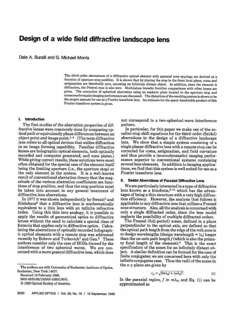
From Eqs. (26) and (27) we see the important resultthat if the aperture stop is placed in the front focalplane, as shown in the schematic layout of Fig. 2 (i.e.,the lens is made telecentric in image space), then t = fand third-order coma and astigmatism are identicallyzero. Since the Petzval term is also zero, both tangen-tial and sagittal fields are flat. This is in contrast tothe glass landscape lens, which has a flat field in onlyone meridian.16 Since the remaining third-orderspherical aberration limits this diffractive lens to oper-ation at relatively modest apertures, the higher orderaberrations are essentially negligible compared withthe Seidel aberrations for practical field angles. Thusthe third-order aberrations for this telecentric paraxialdiffractive lens are
SI = SI, = S 0-yS= Yu . 0
(30)
(31)
(32)
where t is the distance from the stop to the diffractivelens. Due to the large amount of chromatic aberrationinherent in diffractive optics [see Eq. (15)], a diffrac-tive lens singlet is limited to monochromatic opera-tion. Since a diffractive kinoform can be designed foroperation at any center wavelength, we consider onlythe case of X = X0. Using Eqs. (10)-(14) and (24) inEqs. (19)-(23), we find the resultant aberrations with X
SI. = ' rX(25)
=,
/3 (6
t f
7Aperture ParaxialStop Diffractive
Lens
OpticalAxis
ImagePlane
Fig. 2. Layout of telecentric paraxial diffractive lens. The aper-ture stop for the system is placed in the front focal plane of the lens.
Equation (31) indicates that the field aberrations ofcoma, astigmatism, and curvature of field are identi-cally zero for this system, allowing for the imaging ofextended objects with little variation in image qualityacross the field. (Of course, the aperture size is limitedby the uncorrected spherical aberration. The toler-ance on aperture size is discussed in a following sec-tion.) This diffractive lens singlet system exhibits adegree of isoplanatism comparable with refractive sys-tems containing more elements.
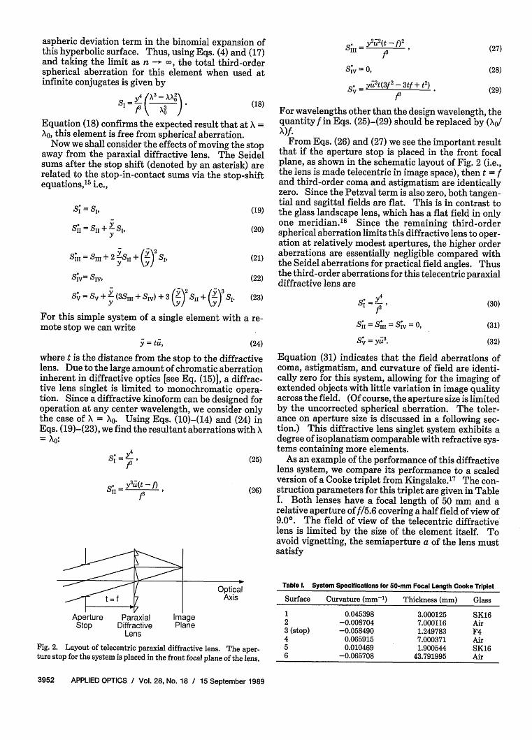
As an example of the performance of this diffractivelens system, we compare its performance to a scaledversion of a Cooke triplet from Kingslake.17 The con-struction parameters for this triplet are given in TableI. Both lenses have a focal length of 50 mm and arelative aperture of f/5.6 covering a half field of view of9.00. The field of view of the telecentric diffractivelens is limited by the size of the element itself. Toavoid vignetting, the semiaperture a of the lens mustsatisfy
Table 1. System Specifications for 50-mm Focal Length Cooke Triplet
Surface Curvature (mm-') Thickness (mm) Glass
1 0.045398 3.000125 SK162 -0.008704 7.000116 Air3 (stop) -0.058490 1.249783 F44 0.065915 7.000371 Air5 0.010469 1.900544 SK166 -0.065708 43.791995 Air
3952 APPLIED OPTICS / Vol. 28, No. 18 / 15 September 1989
-r -- e- _

FOV - 9.0 deg b.
Dif fraction Limit
0.8
0.6
0.4
0.2
c X O~~~~~~~~~~~~n Ais
|- fraction Limit
. I . , . I . , S0 000 10 200 250 300 0 t00 lAO 200 250 300 S0 tOO 1O 200 250 300
Spatial Frequency n llnes/J Spatal Fquency hInes/n SpatIal Freqecy in ,es/._
Fig. 3. Modulation transfer functions for f15.6 Cooke triplet; (a) full field (9.0° off-axis); (b) 0.7 field (6.33° off-axis); (c) on-axis. The focal
length is 50 mm, and the design wavelength is 0.58756,um. The triplet system specifications are given in Table I. In each plot, three curves are
given-the diffraction limited MTF and the system MTF for tangential and sagittal orientations of the target grating lines.
a} .0 FOV * 9.0 deg b) 0.0 WOV - 6.33 dge c 1.0 o0 Ais
0.8 0.8 0.8
tif ..action~ Wiit Oiff fr.ctio LiW it frac..tio Limit
0.6 0.6 0.6
0.4 -0.4 -0.4-
0.20 0.2 -0.2
S0 000 000 200 250 300 50 t00 10 200 250 300 50 t00 00o 200 250 300
Spatial Frequency hInes/wi Spatial Frequency (lines/-I Spatial Frequency lines/
Fig.4. Modulation transfer functions forf/5.6 telecentric paraxial diffractive lens; (a) full field (9.0 off-axis); (b) 0.7 field (6.33° off-axis); (c)
on-axis. The focal length is 50 mm, and the design wavelength is 0.58756 im.
WFOV 9.0 deg b)
Diffrattion Licit
0 100 100 200 250 300Spatial Frequency hines/wi
1.0 lan Ais
0.8
0 Mtraction Li-it0.6
0.4 -
0.2-
00 i00 100 000 250Spatial Frequency hlInes/wil
300
Fig.5. Modulation transfer functions for f/5.6 optically recorded HOE: (a) full field (9.0° off-axis); (b) 0.7 field (6.33° off-axis); (c) on-axis.
The focal length is 50 mm, and the design wavelength is 0.58756 jm.
Table II. System Specifications for 50-mm Focal Length GermaniumLandscape Lens
Surface Curvature (mm-') Thickness (mm) Glass
1 (stop) 0.000000 43.112883 Air2 0.004314 4.000020 Ge3 -0.002376 48.869530 Air
15 September 1989 / Vol. 28, No. 18 / APPLIED OPTICS 3953
00 100 100 200Spatial Frequency fines/wi
250 30D
al dI 1.0
y+y-a, (33)
or, equivalently for this system,
y + f tan(O) < a. (34)
Using Eq. (34) as an equality, we can solve for 0 max, thelargest unvignetted field angle. Using the relations
yf = Fteme (35)
f = l~n8^ (36)
we find the result
Om.=~ =tan- 1 1371[2 Fl~5 Fs4# tem
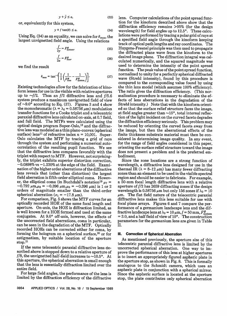
Existing technologies allow for the fabrication of kino-form lenses for use in the visible with relative aperturesup to -f/2. Thus an f/2 diffractive lens and f/15.6system produce a maximum unvignetted field of viewof -9.0° according to Eq. (37). Figures 3 and 4 showthe monochromatic ( = Xo = 0.58756,um) modulationtransfer functions for a Cooke triplet and a telecentricparaxial diffractive lens calculated on-axis, at 0.7 field,and full field. The MTFs were calculated using theoptical design program Super-Oslo,18 and the diffrac-tive lens was modeled as a thin plano-convex (sphericalsurface) lens" of refractive index n = 10,001. Super-Oslo calculates the MTF by tracing a grid of raysthrough the system and performing a numerical auto-correlation of the resulting pupil function. We seethat the diffractive lens compares favorably with thetriplet with respect to MTF. However, not surprising-ly, the triplet exhibits superior distortion correction,-0.0898% vs -1.230% at the edge of the field. Exami-nation of the higher order aberrations of the diffractivelens reveals that (other than distortion) the largestfield aberration is fifth-order elliptical coma. Howev-er, the elliptical coma (in Buchdahl's notation1 9 7 =-0.792 m,M = -0.396 m,M9 = -0.396 ,m) is 1 or 2orders of magnitude smaller than the third-orderspherical aberration ( = -17.8 Mm).
For comparison, Fig. 5 shows the MTF curves for anoptically recorded HOE of the same focal length andaperture. On-axis, the HOE is diffraction limited, asis well known for a HOE formed and used at the sameconjugates. At 9.00 off-axis, however, the effects ofthe uncorrected field aberrations, coma in particular,can be seen in the degradation of the MTF. Opticallyrecorded HOEs can be corrected either for coma, byforming the hologram on a spherical surface, 20 or forastigmatism, by suitable location of the aperturestop.2 1
If the same telecentric paraxial diffractive lens de-scribed above is stopped down to a relative aperture off18, the unvignetted half-field increases to -10.5°. Atthis aperture, the spherical aberration is small enoughthat the lens is essentially diffraction limited over theentire field.
For large field angles, the performance of the lens islimited by the diffraction efficiency of the diffractive
lens. Computer calculations of the point spread func-tion for the kinoform described above show that thediffraction efficiency remains >95% (for the designwavelength) for field angles up to 12.50. These calcu-lations were performed by tracing a polar grid of rays ata specified field angle through the kinoform keepingtrack of optical path lengths and ray coordinates. TheHuygens-Fresnel principle was then used to propagatethe diffracted plane wave from the kinoform to thedesired image plane. The diffraction integral was cal-culated numerically, and the squared magnitude wasused to 'determine the intensity of the point spreadfunction. The peak value of the point spread function,normalized to unity for a perfectly spherical diffractedwave (Strehl intensity), found by this procedure iscompared to the corresponding value found by usingthe thin lens model (which assumes 100% efficiency).The ratio gives the diffraction efficiency. (This nor-malization procedure is necessary to eliminate the ef-fects of lens aberrations in the degradation of theStrehl intensity.) Note that with the kinoform orient-ed so that the surface relief structure faces the image,at field angles greater than -15°, total internal reflec-tion of the light incident on the curved facets degradesthe diffraction efficiency seriously. This problem maybe reduced by orienting the curved facets away fromthe image, but then the aberrational effects of thefinite thickness substrate material must then be con-sidered in determining image quality. In any event,for the range of field angles considered in this paper,orienting the surface relief structure toward the imagedoes not present a problem and is the preferred em-bodiment.
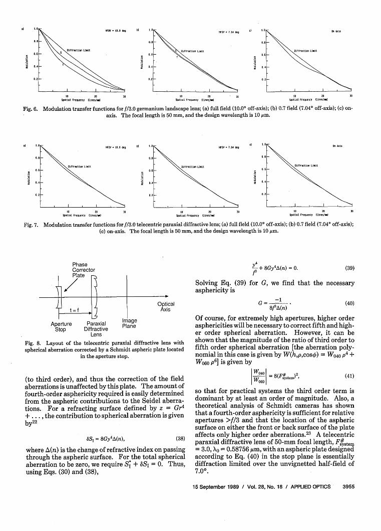
Since the zone locations are a strong function ofwavelength, a diffractive lens designed for use in thethermal IR ( = 8-12,Mm) has many fewer diffractingzones than an element to be used in the visible spectralregion and should be easier to fabricate. For example,a 50-mm focal length diffractive lens with a relativeaperture of f/2 has 2659 diffracting zones if the designwavelength is 0.58756 Am but only 156 zones if X0 = 10,um. The flat field nature of the telecentric paraxialdiffractive lens makes this lens suitable for use withfocal plane arrays. Figures 6 and 7 compare the per-formance of a germanium landscape lens and the dif-fractive landscape lens at Xo = 10,m, f = 50 mm, F#stem= 3.0, and a half field of view of 100. The constructionparameters for the germanium lens are given in TableII.
111. Correction of Spherical Aberration
As mentioned previously, the aperture size of thistelecentric paraxial diffractive lens is limited by theuncorrected spherical aberration. One way to im-prove the performance of this lens at higher aperturesis to insert an appropriately figured aspheric plate inthe aperture stop, as shown in Fig. 8. This is formallyanalogous to the Schmidt camera, which uses anaspheric plate in conjunction with a spherical mirror.Since the aspheric surface is located at the aperturestop, the plate contributes only spherical aberration
3954 APPLIED OPTICS / Vol. 28, No. 18 / 15 September 1989
my .
t0 20 30 to 20 30 10 20 30Spatial Frequency (lnes/"w Spatial Frequency (lines"/w Spatial Frequeny (lines/wi
Fig. 6. Modulation transfer functions for ff3.0 germanium landscape lens; (a) full field (10.00 off-axis); (b) 0.7 field (7.04° off-axis); (c) on-axis. The focal length is 50 mm, and the design wavelength is 10gm.
IfOV *- 10.0 deg
0 f ..cto Limit
to 20Spatial Frequency lInes/w
b) 8.a
0.8
0.6
0.4
0.2
30
HFOV 7.04 deg
Iff.ractios LImIt
I I I I
to 20Spatial Frequency ll.nes/wh
30
cl 1.
0.8
0.8
0.4
0.21
lftiction Limit
to 20Spatial Frequency llnes/wh
Fig. 7. Modulation transfer functions for ff3.0 telecentric paraxial diffractive lens; (a) full field (10.00 off-axis); (b) 0.7 field (7.04° off-axis);(c) on-axis. The focal length is 50 mm, and the design wavelength is 10 Am.
+
PhaseCorrectorPlate
t =f
Aperture PeStop Diff
Y + 8Gy 4A(n) = 0.f3
Solving Eq. (39) for G, we find that the necessaryasphericity is
OpticalAxis
iraxial Planeractive PlaneLens
Fig. 8. Layout of the telecentric paraxial diffractive lens withspherical aberration corrected by a Schmidt aspheric plate located
in the aperture stop.
(to third order), and thus the correction of the fieldaberrations is unaffected by this plate. The amount offourth-order asphericity required is easily determinedfrom the aspheric contributions to the Seidel aberra-tions. For a refracting surface defined by z = Gr4
+ . .. , the contribution to spherical aberration is givenby22
S = 8Gy4A(n), (38)
where A(n) is the change of refractive index on passingthrough the aspheric surface. For the total sphericalaberration to be zero, we require S* + 6S, = 0. Thus,using Eqs. (30) and (38),
G = -18f3A(n)
Of course, for extremely high apertures, higher orderasphericities will be necessary to correct fifth and high-er order spherical aberration. However, it can beshown that the magnitude of the ratio of third order tofifth order spherical aberration [the aberration poly-nomial in this case is given by W(h,p,cosk) = W0 4 0 p 4 +W 0 6 0 p6 ] is given by
W040 = 8(Ffstem)2 e (41)
so that for practical systems the third order term isdominant by at least an order of magnitude. Also, atheoretical analysis of Schmidt cameras has shownthat a fourth-order asphericity is sufficient for relativeapertures >f/3 and that the location of the asphericsurface on either the front or back surface of the plateaffects only higher order aberrations.2 3 A telecentricparaxial diffractive lens of 50-mm focal length, F#st= 3.0, Xo = 0.58756 gm, with an aspheric plate designedaccording to Eq. (40) in the stop plane is essentiallydiffraction limited over the unvignetted half-field of7.00.
15 September 1989 / Vol. 28, No. 18 / APPLIED OPTICS 3955
al 1.8
0.8
0.8
0. 4
0.2
30
(39)
(40)l' ' I | I _
b) cl

Olf racto LImit
s - I cm
I I I
50 000 050 200Spatal Frequesty (lInes/wI
1.0
0.8
0.1
0.4
0.2
50 t00 tOOSpatIal Frequency lInes/wI
200
50 100 150 200Spatial Freqecy (lInes/w)
lff acton LImIt
.\
-I0 I
SO 000 0I" 200Spatial Frequency llnes/I
Fig. 9. On-axis polychromatic modulation transfer functions for Gaussian line shapes of various standard deviations a. The focal length is 50mm, Xpcak = 0.544sum, Fs#em = 8: (a) = 1 nm; (b) a = 2 nm; (c) a = 5 nm; (d) a = 10 nm.
IV. Quasi-Monochromatic Performance
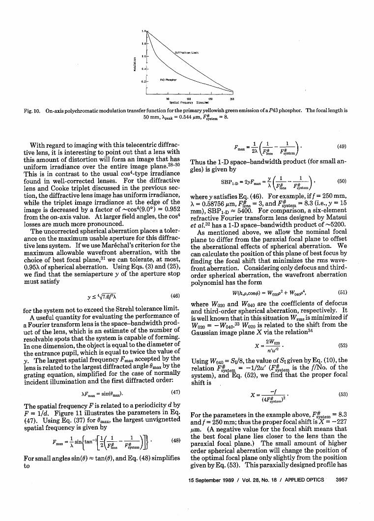
All the analysis to this point has assumed a mono-chromatic object. In actuality, of course, no physicalsource is truly monochromatic. To assess the imagingperformance of this diffractive lens in quasi-mono-chromatic light, we used Super-Oslo to calculate poly-chromatic MTFs for finite bandwidth illumination.Figures 9(a)-(d) show the polychromatic on-axis MTFfor Gaussian spectral line shapes of standard devi-ations of a = 1,2, 5, and 10 nm, respectively. The lensused in these calculations had a 50-mm focal length atthe design wavelength (the mean of the Gaussian spec-tral line) and an f/No. of F#stem = 8. The plots clearlyshow the degradation of performance with increasinglinewidth, as would be expected, given the largeamount of chromatic aberration. As an illustrativeexample of typical performance with an actual quasi-monochromatic source, Fig. 10 shows the polychro-matic on-axis MTF for a diffractive lens with the spec-tral weightings assigned according to the relativeintensities in the primary yellowish green emission(Xpeak = 0.544 Am) of a P43 phosphor. 2 4 We see thatthe performance has been degraded slightly due to thefinite bandwidth of the source.
ensure a linear relationship between position in thetransform plane and spatial frequency in the object forall spatial frequencies. For an image height accordingto Y = f sin(0), the transverse ray aberration (to thirdorder) should be
e, = f sin(O) - f tan(O)
(42)
Let us now consider the distortion term more care-fully. In terms of transverse ray aberration, third-order distortion appears as a term of the form
(43)
where ey is the transverse ray error in the meridionalplane, relative to the Gaussian image position, a5 is theray error coefficient, and h is the normalized imageheight. Since the transverse ray error is related towavefront aberration via the derivative,27 there is arelationship between the coefficients a5 and Sv, name-ly,
1/2SV05 =nu (44)
V. Paraxial Diffractive Lens as a Fourier Transform Lens
A lens designed for use with an infinitely distantobject with the aperture stop in the front focal plane isthe configuration necessary for use in a Fourier trans-form system.25'26 An additional requirement for thisuse is that the image height Y formed by the lensshould follow the rule Y = f sin(a) rather than Y = ftan(0), which is the rule for a lens that is designed to bedistortion free. Image heights proportional to sin(0)
where n' and u' are the refractive index and paraxialmarginal ray angle, respectively, in image space.Thus, using Eqs. (32) and (44) and n' = 1.0 and u' =-ylf, we find
05 = 2 I! 3.2
(45)
Since h = 0/0m = 0/u, we see that to third order thislens forms an image height according to the rule Y = fsin(0), making it ideally suited for use as a Fouriertransform lens.
3956 APPLIED OPTICS / Vol. 28, No. 18 / 15 September 1989
0.8
0.6
0.4S
0.2
I
*) .0 b)
o3 -1 M.- 0+-+3 ... )] = 2
Cf = ash
o3=f 0--+
R 6 ... )
0 too 15o 200Spatial Frequency (lines/wI
Fig. 10. On-axis polychromatic modulation transfer function for the primary yellowish green emission ofaP43 phosphor. The focal length is50 mm, Xpeak = 0.544 im, Fs#tem = 8.
With regard to imaging with this telecentric diffrac-tive lens, it is interesting to point out that a lens withthis amount of distortion will form an image that hasuniform irradiance over the entire image plane.2 830
This is in contrast to the usual cos4-type irradiancefound in well-corrected lenses. For the diffractivelens and Cooke triplet discussed in the previous sec-tion, the diffractive lens image has uniform irradiance,while the triplet image irradiance at the edge of theimage is decreased by a factor of -cos 4(9.0 0) = 0.952from the on-axis value. At larger field angles, the cos4losses are much more pronounced.
The uncorrected spherical aberration places a toler-ance on the maximum usable aperture for this diffrac-tive lens system. If we use Marechal's criterion for themaximum allowable wavefront aberration, with thechoice of best focal plane, 31 we can tolerate, at most,0.95X of spherical aberration. Using Eqs. (3) and (25),we find that the semiaperture y of the aperture stopmust satisfy
max 2X kFl~S Fyttem)(49)
Thus the 1-D space-bandwidth product (for small an-gles) is given by
SBPlD = 2Fmax =y 1 1# )lens system
(50)
where y satisfies Eq. (46). For example, if f = 250 mm,A = 0.58756 Am, FflnS = 3, and F#ystem = 8-3 (i.e., y = 15mm), SBP1,D 5400. For comparison, a six-elementrefractive Fourier transform lens designed by Matsuiet al.3 2 has a 1-D space-bandwidth product of -5200.
As mentioned above, we allow the nominal focalplane to differ from the paraxial focal plane to offsetthe aberrational effects of spherical aberration. Wecan calculate the position of this plane of best focus byfinding the focal shift that minimizes the rms wave-front aberration. Considering only defocus and third-order spherical aberration, the wavefront aberrationpolynomial has the form
Y ' 47.6f3 X (46)
for the system not to exceed the Strehl tolerance limit.A useful quantity for evaluating the performance of
a Fourier transform lens is the space-bandwidth prod-uct of the lens, which is an estimate of the number ofresolvable spots that the system is capable of forming.In one dimension, the object is equal to the diameter ofthe entrance pupil, which is equal to twice the value ofy. The largest spatial frequency Fmax accepted by thelens is related to the largest diffracted angle Omax by thegrating equation, simplified for the case of normallyincident illumination and the first diffracted order:
W(h,p,cos5) = W02Op2 + W 40 p4, (51)
where W020 and W040 are the coefficients of defocusand third-order spherical aberration, respectively. Itis well known that in this situation Wrms is minimized ifW020 = -W 040.33 W020 is related to the shift from theGaussian image plane X via the relation34
x 2W20/ /,2 (52)
Using W040 = SI/8, the value of SI given by Eq. (10), therelation Fystem = -1/2u' (Fs#stem is the f/No. of thesystem), and Eq. (52), we find that the proper focalshift is
XFnax = sin(Omax). (47)
The spatial frequency F is related to a periodicity d byF = 1/d. Figure 11 illustrates the parameters in Eq.(47). Using Eq. (37) for Omax, the largest unvignettedspatial frequency is given by
Fmax = intan - ' - 1 t]I (48)
sio L in. Ff6.em
For small angles sin(O) tan(O), and Eq. (48) simplifiesto
x -fWtys~te. )2
(53)
For the parameters in the example above, F#stem = 8.3and f = 250 mm; thus the proper focal shift is X = -227,m. (A negative value for the focal shift means thatthe best focal plane lies closer to the lens than theparaxial focal plane.) The small amount of higherorder spherical aberration will change the position ofthe optimal focal plane only slightly from the positiongiven by Eq. (53). This paraxially designed profile has
15 September 1989 / Vol. 28, No. 18 / APPLIED OPTICS' 3957
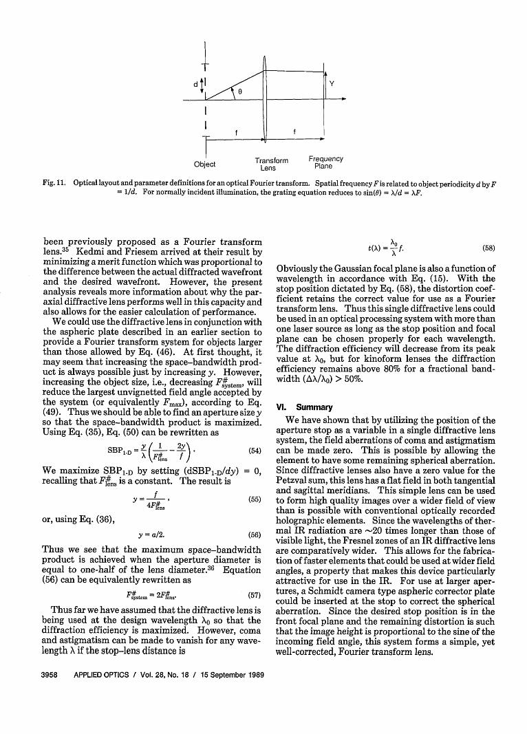
Object Transform FrequencyObject Lens Plane
Fig. 11. Optical layout and parameter definitions for an optical Fourier transform. Spatial frequencyFis related to object periodicity d byF= 1/d. For normally incident illumination, the grating equation reduces to sin(O) = /d = XF.
been previously proposed as a Fourier transformlens.35 Kedmi and Friesem arrived at their result byminimizing a merit function which was proportional tothe difference between the actual diffracted wavefrontand the desired wavefront. However, the presentanalysis reveals more information about why the par-axial diffractive lens performs well in this capacity andalso allows for the easier calculation of performance.
We could use the diffractive lens in conjunction withthe aspheric plate described in an earlier section toprovide a Fourier transform system for objects largerthan those allowed by Eq. (46). At first thought, itmay seem that increasing the space-bandwidth prod-uct is always possible just by increasing y. However,increasing the object size, i.e., decreasing Fsfstem, willreduce the largest unvignetted field angle accepted bythe system (or equivalently Fmax), according to Eq.(49). Thus we should be able to find an aperture sizeyso that the space-bandwidth product is maximized.Using Eq. (35), Eq. (50) can be rewritten as
SBP / D 1 2y\ 54
(W~en. f(4We maximize SBP1 D by setting (dSBPlD/dy) = 0,recalling that Fli. is a constant. The result is
f ,f (55)4Flens
or, using Eq. (36),
y = a/2. (56)
Thus we see that the maximum space-bandwidthproduct is achieved when the aperture diameter isequal to one-half of the lens diameter.36 Equation(56) can be equivalently rewritten as
Ff4 .tem= 2Fe..- (57)
Thus far we have assumed that the diffractive lens isbeing used at the design wavelength X0 so that thediffraction efficiency is maximized. However, comaand astigmatism can be made to vanish for any wave-length X if the stop-lens distance is
t( ) = -i f.X
(58)
Obviously the Gaussian focal plane is also a function ofwavelength in accordance with Eq. (15). With thestop position dictated by Eq. (58), the distortion coef-ficient retains the correct value for use as a Fouriertransform lens. Thus this single diffractive lens couldbe used in an optical processing system with more thanone laser source as long as the stop position and focalplane can be chosen properly for each wavelength.The diffraction efficiency will decrease from its peakvalue at X0, but for kinoform lenses the diffractionefficiency remains above 80% for a fractional band-width (AX/Xo) > 50%.
VI. Summary
We have shown that by utilizing the position of theaperture stop as a variable in a single diffractive lenssystem, the field aberrations of coma and astigmatismcan be made zero. This is possible by allowing theelement to have some remaining spherical aberration.Since diffractive lenses also have a zero value for thePetzval sum, this lens has a flat field in both tangentialand sagittal meridians. This simple lens can be usedto form high quality images over a wider field of viewthan is possible with conventional optically recordedholographic elements. Since the wavelengths of ther-mal IR radiation are -20 times longer than those ofvisible light, the Fresnel zones of an IR diffractive lensare comparatively wider. This allows for the fabrica-tion of faster elements that could be used at wider fieldangles, a property that makes this device particularlyattractive for use in the IR. For use at larger aper-tures, a Schmidt camera type aspheric corrector platecould be inserted at the stop to correct the sphericalaberration. Since the desired stop position is in thefront focal plane and the remaining distortion is suchthat the image height is proportional to the sine of theincoming field angle, this system forms a simple, yetwell-corrected, Fourier transform lens.
3958 APPLIED OPTICS / Vol. 28, No. 18 / 15 September 1989

References
1. K. Kamiya, "Theory of Fresnel Zone Plate," Sci. Light 12,35-49(1963).
2. R. W. Meier, "Magnification and Third-Order Aberrations inHolography," J. Opt. Soc. Am. 55, 987-992 (1965).
3. E. B. Champagne, "Nonparaxial Imaging, Magnification, andAberration Properties in Holography," J. Opt. Soc. Am. 57, 51-55 (1967).
4. M. Young, "Zone Plates and Their Aberrations," J. Opt. Soc.Am. 62, 972-976 (1972).
5. W. C. Sweatt, "Describing Holographic and Optical Elements asLenses," J. Opt. Soc. Am. 67, 803-808 (1977).
6. W. A. Kleinhans, "Aberrations of Curved Zone Plates and Fres-nel Lenses," Appl. Opt. 16, 1701-1704 (1977).
7. S. T. Bobrov and Yu. G. Turkevich, "Method of Calculating theWave Aberrations of Complex Holographic Systems," Opt.Spectrosc. USSR 46, 555-557 (1979).
8. M. A. Gan, "Third-Order Aberrations and the FundamentalParameters of Axisymmetrical Holographic Elements," Opt.Spectrosc. USSR 47,419-422 (1979).
9. L. B. Lesem, P. M. Hirsch, and J. A. Jordan, Jr., "The Kinoform:a New Wavefront Reconstruction Device," IBM J. Res. Dev. 13,150-155 (1969).
10. J. A. Jordan, Jr., P. M. Hirsch, L. B. Lesem, and D. L. Van Rooy,"Kinoform Lenses," Appl Opt. 9, 1883-1887 (1970).
11. D. A. Buralli, G. M. Morris, and J. R. Rogers, "Optical Perfor-mance of Holographic Kinoforms," Appl. Opt. 28, 976-983(1989).
12. W. T. Welford, Abberations of Optical Systems (Hilger, Bristol,1986), pp. 226-234.
13. Reference 12, pp. 130-140.14. R. Kingslake, Lens Design Fundamentals (Academic, Orlando,
FL, 1978), p. 113.15. Reference 12, pp. 148-152.16. Reference 14, pp. 211-215.17. Reference 14, p. 293.18. Super-Oslo is a trademark of Sinclair Optics, 6780 Palmyra Rd,
Fairport, NY 14450.
19. F. D. Cruickshank and G. A. Hills, "Use of Optical AberrationCoefficients in Optical Design," J. Opt. Soc. Am. 50, 379-387(1960).
20. W. T. Welford, "Aplanatic Hologram Lenses on Spherical Surfa-ces," Opt. Commun. 9, 268-269 (1973); see also W. T. Welford,"Isoplanatism and Holography," Opt. Commun. 8, 239-243(1973).
21. R. W. Smith, "A Flat Field Holographic Lens with no First OrderAstigmatism," Opt. Commun. 19,245-247 (1976); see also R. W.Smith, "Astigmatism Free Holographic Lens Elements," Opt.Commun. 21, 102-105 (1977); R. W. Smith, "The s and t Formu-lae for Holographic Lens Elements," Opt. Commun. 21,106-109(1977).
22. Reference 12, pp. 152-153.23. E. H. Linfoot, "On the Optics of the Schmidt Camera," Mon.
Not. R. Astron. Soc. 109, 279-297 (1949).24. Phosphor data taken from "Optical Characteristics of Cathode
Ray Tube Screens," TEPAC Publication 116, published by theEIA Tube Engineering Panel Advisory Council (Dec. 1980).
25. B. A. F. Blandford, "A New Lens System for Use in OpticalData-Processing," in Optical Instruments and Techniques1969, J. H. Dickson, Ed. (Oriel, Newcastle upon Tyne, 1970), pp.435-443.
26. K. von Bieren, "Lens Design for Optical Fourier TransformSystems," Appl. Opt. 10, 2739-2742 (1971).
27. Reference 12, pp. 93-98.28. M. Reiss, "The cos
4 Law of Illumination," J. Opt. Soc. Am. 35,283-288 (1945).
29. I. C. Gardner, "Validity of the Cosine-Fourth-Power Law ofIllumination," J. Res. Natl. Bur. Stand. 39, 213-219 (1947).
30. M. Reiss, "Notes on the cos4 Law of Illumination," J. Opt. Soc.
Am. 38, 980-986 (1948).31. Reference 12, pp. 241-246.32. Y. Matsui, S. Minami, and S. Yamaguchi, "Fourier Transform
Lens System," U.S. Patent 4,189,214 (19 Feb. 1980).33. Reference 12, p. 244.34. Reference 12, p. 116.35. J. Kedmi and A. A. Friesem, "Optimal Holographic Fourier-
Transform Lens," Appl. Opt. 23, 4015-4019 (1984).36. A. W. Lohmann, "Parallel Interfacing of Integrated Optics with
Free-Space Optics," Optik 76, 53-56 (1987).
The authors would like to acknowledge the supportof this research by DARPA, MIT Lincoln Laboratory,and the 3M Co. D. A. Buralli is grateful for the sup-port of the Kodak Fellows Program. Portions of thiswork were presented as Paper TUMI at the 1988 An-nual Meeting of the Optical Society of America, 30Oct.-4 Nov. 1988, Santa Clara, CA.
15 September 1989 / Vol. 28, No. 18 / APPLIED OPTICS 3959