design of a sensorized guiding catheter for in situ laser ... · design of a sensorized guiding...
TRANSCRIPT

Full Terms & Conditions of access and use can be found athttp://www.tandfonline.com/action/journalInformation?journalCode=icsu21
Download by: [99.57.16.236] Date: 25 September 2017, At: 17:21
Computer Assisted Surgery
ISSN: (Print) 2469-9322 (Online) Journal homepage: http://www.tandfonline.com/loi/icsu21
Design of a sensorized guiding catheter for in situlaser fenestration of endovascular stent
Roberta Piazza, Sara Condino, Aldo Alberti, Raffaella Nice Berchiolli,Gioachino Coppi, Marco Gesi, Vincenzo Ferrari & Mauro Ferrari
To cite this article: Roberta Piazza, Sara Condino, Aldo Alberti, Raffaella Nice Berchiolli,Gioachino Coppi, Marco Gesi, Vincenzo Ferrari & Mauro Ferrari (2017) Design of a sensorizedguiding catheter for in situ laser fenestration of endovascular stent, Computer Assisted Surgery,22:1, 27-38, DOI: 10.1080/24699322.2017.1358403
To link to this article: http://dx.doi.org/10.1080/24699322.2017.1358403
© 2017 The Author(s). Published by InformaUK Limited, trading as Taylor & FrancisGroup.
Published online: 30 Jul 2017.
Submit your article to this journal
Article views: 71
View related articles
View Crossmark data

RESEARCH ARTICLE
Design of a sensorized guiding catheter for in situ laser fenestration ofendovascular stent
Roberta Piazzaa,b,c, Sara Condinoa, Aldo Albertid, Raffaella Nice Berchiollib, Gioachino Coppie, Marco Gesid,Vincenzo Ferraria,c and Mauro Ferraria,b,d
aEndoCAS Center, Department of Translational Research and of New Surgical and Medical Technologies, University of Pisa, Pisa, Italy;bUnit of Vascular Surgery, Department of Translational Research and of New Surgical and Medical Technologies, University of Pisa,Pisa, Italy; cDepartment of Information Engineering, University of Pisa, Pisa, Italy; dDepartment of Translational Research and of NewSurgical and Medical Technologies, University of Pisa, Pisa, Italy; eDepartment of Surgery, Operative Unit of Vascular Surgery,Policlinico of Modena, Modena, Italy
ABSTRACTPurpose: The in situ fenestration of a standard endograft is currently limited by difficulties in tar-geting the fenestration site under fluoroscopic control and by the lack of a safe method to per-forate the graft. Evidence in the literature suggests the use of a 3D electromagnetic navigator toaccurately guide the endovascular instruments to the target and a laser to selectively perforatethe graft. The aim of this work is to provide design guidelines to develop a sensorized catheterto guide the laser tool to the fenestration site and conduct preliminary testing of the feasibilityof the proposed solution.Matherials and methods: Different catheter designs were delineated starting from engineeringconsiderations, then prototypes were preliminarily tested to collect surgeon opinions and tosteer the design process toward the preferred solution reported by the user. Finally, mechanicalsimulations were performed with CathCAD, a design software system for the development ofcomposite tubing for endovascular catheters.Results: Based on surgeon feedback, a 9-French steerable catheter with a stabilization systemwas designed. CathCAD simulations allowed us to define the construction parameters (e.g.,materials and geometric constrains) for the fabrication of composite tubes with mechanical prop-erties (flexural, axial, and torsional rigidities) compatible with target values in the literature forguiding catheters.Conclusion: The presented results preliminarily demonstrate the clinical reasonability and feasi-bility of the designed tool in terms of mechanical properties. Further mechanical tests and exten-sive in vitro clinical trials are required prior to animal testing.
KEYWORDSGuiding catheter;electromagnetic navigation;in situ fenestration;endovascular aorticaneurysm repair
1. Introduction
Endovascular aortic aneurysm repair (EVAR) is a cath-eter-based surgical technique that allows for minimallyinvasive repair of aortic aneurysms with the implant-ation of a stent graft within the aneurysmal sac.Fluoroscopy, a two-dimensional imaging modalitybased on X-ray radiation, is used to support navigationof endovascular instruments through blood vessels.
Maintaining adequate perfusion of collateral vesselsthat originate from the aorta is a key aspect in thetreatment of aortic aneurysms. In case of juxtarenalinfrarenal aneurysms (‘aneurysms that involve theinfrarenal abdominal aorta adjacent to or including thelower margin of renal artery origins’ [1]), traditional
stent grafting can occlude the aortic branches andblock blood flow to vital organs.
For this reason, patient-specific fenestrated stentgrafts with customized holes to preserve flow toessential collateral arteries have been developed [2–4].Fenestrated grafting, however, is technically challeng-ing and time-consuming since stent graft fenestrationsshould be aligned with the target collateral vessels.This procedure requires a great deal of technical skilland precision. In addition, several changes and re-adjustments of the C-Arm position/orientation arenecessary to determine the best viewing direction,which results in prolonged fluoroscopic exposuretimes. Customized grafts are also expensive and notavailable for acute syndromes, since fabrication
CONTACT Sara Condino [email protected] EndoCAS Center, University of Pisa, Cisanello Hospital, Via Paradisa 2, 56124 Pisa, Italy� 2017 The Author(s). Published by Informa UK Limited, trading as Taylor & Francis Group.This is an Open Access article distributed under the terms of the Creative Commons Attribution-NonCommercial License (http://creativecommons.org/licenses/by-nc/4.0/), whichpermits unrestricted non-commercial use, distribution, and reproduction in any medium, provided the original work is properly cited.
COMPUTER ASSISTED SURGERY, 2017VOL. 22, NO. 1, 27–38https://doi.org/10.1080/24699322.2017.1358403
Dow
nloa
ded
by [
99.5
7.16
.236
] at
17:
21 2
5 Se
ptem
ber
2017

requires several days. Therefore, alternatives, such asthe in situ fenestration of a standard stent graft, havebeen proposed [5]. However, the reliability of this pro-cedure, especially for abdominal aneurysms, is limitedby the lack of a safe method to perforate the graftand by the difficulties in identifying the target fenes-tration site because after endograft deployment, thecontrast medium flow is blocked by the endograftwall, thus inhibiting visualization of the collateralarteries by angiography.
In regard to the first issue, recent studies have pro-posed the use of laser systems to selectively and rap-idly perforate the graft material preventing injuries tothe arterial wall [6–9]. Concerning the second issue,our research group and others [10–13] have demon-strated that a three-dimensional (3 D) computer-aidedguidance system, based on the electromagnetic (EM)tracking of the surgical tools, can be a reliable solutionto guide the endovascular instruments to the targetsite. These systems can use intraoperative data, suchas 3D ultrasound or 3D rotational angiography, as asource to extract the 3D model of the patient anat-omy or important information for guidance of theendovascular instruments, such as vessel lumen cen-terline [14–16].
The idea behind this work is that the integration ofa laser system into a 3D EM navigation platform canpotentially overcome the limitations of the present insitu fenestration technique, providing the surgeonwith a selective fenestration tool whose position andorientation can be accurately tracked in real timewithin a 3D virtual model of the patient vasculature.
More specifically, the idea is to use a guidewiretipped laser fiber (a laser fiber incorporated into aguidewire) to deliver the laser energy to the graftmaterial at the target fenestration site. The efficacy ofsuch a fenestration system is heavily dependent onthe navigator accuracy, proper setting of the laser, and
proper design of the device used as a guiding catheterfor the laser tool.
This work focuses on this latter aspect, and it aimsto provide a sensorized guiding catheter for the navi-gation and positioning of a guidewire tipped laserfiber at the fenestration site. First, the main require-ments of this catheter are discussed and differentdesign strategies to accomplish the desired specifica-tions are described. Finally, the results of preliminarytests performed to define the optimal solution from aclinical point of view are presented and the mechan-ical feasibility of the selected design is verified.
2. Materials and methods
A guiding catheter is an endovascular device used tofacilitate passage of a smaller catheter or anotherendovascular instrument through a tortuous region tothe intended target area within the vessel [17]. As aspecific application, the guiding catheter will be usedto navigate a fenestration tool, i.e., a laser fiber incor-porated into a 0.035’’ nitinol tube.
First and foremost, this guiding catheter shouldreach the designated fenestration site without causinginjury to the arterial wall. More specifically, it shouldbe easily advanced through the femoral arteries intothe abdominal aorta to reach the appropriate longitu-dinal position along the main axis of the aorta/pros-thesis and then easily rotated to correctly orient thelaser fiber tip toward the fenestration site.
For optimal fenestration of the endoprosthesis, thelaser fiber tip, and thus the catheter tip, should bepositioned perpendicular to the graft surface [18]. Thisrequires proper bending of the catheter tip. Finally,once the proper longitudinal and rotational alignmentsare reached, the mechanical support and stability ofthe catheter must be maintained during fenestration(Figure 1).
Figure 1. Targeting of the stent graft fenestration site (highlighted with a yellow circle) during an EVAR procedure. Two coordin-ate systems are represented: a global system (XYZ) in red and a local system (xyz) related to the guiding catheter body in black.Precise targeting requires proper catheter positioning along the longitudinal direction (Z axis), rotation around the catheter mainaxis (z axis), and bending of the catheter tip (in the yz plane).
28 R. PIAZZA ET AL.
Dow
nloa
ded
by [
99.5
7.16
.236
] at
17:
21 2
5 Se
ptem
ber
2017

To meet these requirements, the catheter should bedesigned to provide a proper pushability (the abilityto transmit the force along the catheter main axis andto push the catheter through the vascular system andthe stenoses to reach its final destination), torqueabil-ity (the ability to rotate the catheter tip by turning itsproximal portion), and flexibility (the ability of thecatheter to conform to the vascular anatomy, reducingthe force applied to the tissue). These properties areclosely related to the catheter size, material, andemployment of reinforcing fibers in the form ofbraiding.
Moreover, other major issues to be considered inthe catheter design are the ability to accurately guideand align the catheter tip to the fenestration target,and catheter stability during fenestration. Lastly,minute EM sensor coils should be integrated into thedistal portion of the catheter to accurately track theposition of the tip in real time and to reconstructthe curvature of the distal part of the tip [11].
In the following paragraphs, some important mech-anical properties, including catheter pushability, tor-queability, and flexibility, are discussed. Afterwards,possible design strategies for catheter stabilization,bending of the catheter tip (to place the laser fiber tipperpendicular to the graft surface), and sensorizationare described. Then, methods to test these solutionsare described in order to obtain preliminary feedbackfrom surgeons. Lastly, a design for the user-preferredsolution is proposed to define possible geometriesand fabrication materials based on simulations with ofthe mechanical properties.
2.1 Catheter design
Mechanical properties
The pushability, torqueability, and flexibility of a cath-eter are, respectively, determined by the axial, flexural,and torsional rigidity. Several studies have evaluatedthe optimal rigidity values for diagnostic and guidingcatheters designed for various endovascular applica-tions [19–25]. As compared to diagnostic catheters,guiding catheters have a stiffer shaft, larger internaldiameter, and feature sufficient axial and torsionalrigidity, allowing the user to easily push the catheterthrough the vascular system to control the torque forproper manipulation. The flexural rigidity should bevariable, decreasing towards the tip, to allow passageof the catheter through tortuous sections of the car-diovascular system without causing injury to the arter-ial wall [25]. For these reasons, composite tubedesigns using more plastic materials are usually
employed. Moreover, braided structures are commonlyused to enhance catheter torqueability. As a result,guiding catheters are generally composed of an innerlayer, a reinforcement layer, and an outer layer [26].
In regard to the reinforcement layer, there is a widevariety of braided meshes available from manufac-turers with different materials, shapes, sizes, numbersof wires, and braid angles between the longitudinalaxis of the mesh and the mesh wires (Figure 2).Typically, braided meshes with a lower angle exhibit agreater stiffness, while a higher angle has a resistanceto kinking of the flexible tube [27].
For our specific application, a three layer braidedsolution was selected and literature values for braidedcatheters [25] were considered as target rigidity values(Table 1).
For simple tubular structures the axial (EA),flexural (EI), and torsional (GJ) rigidity can be simplycalculated as:
EA ¼ Epðr2o � r2i Þ (1)
EI ¼ Epðr4o � r4i Þ
4(2)
GJ ¼ Gpðr4o � r4i Þ
2(3)
Where ro and ri are the outer and inner radii ofthe tube; A is the cross-sectional area; I and J are the
Figure 2. Example of a guiding catheter structure made ofthree different layers. The reinforcement layer is comprised ofa braided mesh characterized by a braid angle that changesthe flexibility and torque response of the catheter.
Table 1. Target rigidity values for guidingcatheters.Rigidity Reference Values
Flexural 100–945 10�6 (N m2)Torsional �1400 10�6 (N m2)Axial �450 (N)
COMPUTER ASSISTED SURGERY 29
Dow
nloa
ded
by [
99.5
7.16
.236
] at
17:
21 2
5 Se
ptem
ber
2017
second moment of area and polar moment of inertia;and E and G are the elastic and shear moduli of thetube constructive material.
Estimation of the mechanical properties of multi-layered braided catheters is more complex and can beperformed using software based on finite element ana-lysis. In this work, CathCAD (Roth Technologies, SanAntonio, TX, USA), a commercially available softwareto predict the mechanical properties of a catheter, wasused to identify possible design solutions with thedesired mechanical specifications (see ExperimentalEvaluation - Mechanical Properties Prediction).
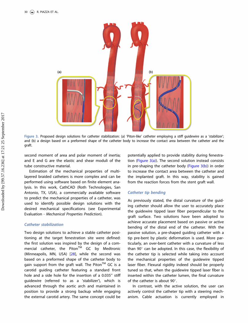
Catheter stabilization
Two design solutions to achieve a stable catheter posi-tioning at the target fenestration site were defined:the first solution was inspired by the design of a com-mercial catheter, the PitonTM GC by Medtronic(Minneapolis, MN, USA) [28], while the second wasbased on a preformed shape of the catheter body togain support from the graft wall. The PitonTM GC is acarotid guiding catheter featuring a standard fronthole and a side hole for the insertion of a 0.035’’ stiffguidewire (referred to as a 'stabilizer'), which isadvanced through the aortic arch and maintained inposition to provide a strong backup while engagingthe external carotid artery. The same concept could be
potentially applied to provide stability during fenestra-tion (Figure 3(a)). The second solution instead consistsin pre-shaping the catheter body (Figure 3(b)) in orderto increase the contact area between the catheter andthe implanted graft. In this way, stability is gainedfrom the reaction forces from the stent graft wall.
Catheter tip bending
As previously stated, the distal curvature of the guid-ing catheter should allow the user to accurately placethe guidewire tipped laser fiber perpendicular to thegraft surface. Two solutions have been adopted toachieve accurate placement based on passive or activebending of the distal end of the catheter. With thepassive solution, a pre-shaped guiding catheter with atip pre-bent by plastic deformation is used. More par-ticularly, an over-bent catheter with a curvature of lessthan 90� can be adopted. In this case, the flexibility ofthe catheter tip is selected while taking into accountthe mechanical properties of the guidewire tippedlaser fiber. Flexural rigidity indeed should be properlytuned so that, when the guidewire tipped laser fiber isinserted within the catheter lumen, the final curvatureof the catheter is about 90�.
In contrast, with the active solution, the user canactively control the catheter tip with a steering mech-anism. Cable actuation is currently employed in
Figure 3. Proposed design solutions for catheter stabilization: (a) ‘Piton-like’ catheter employing a stiff guidewire as a ‘stabilizer’;and (b) a design based on a preformed shape of the catheter body to increase the contact area between the catheter and thegraft.
30 R. PIAZZA ET AL.
Dow
nloa
ded
by [
99.5
7.16
.236
] at
17:
21 2
5 Se
ptem
ber
2017
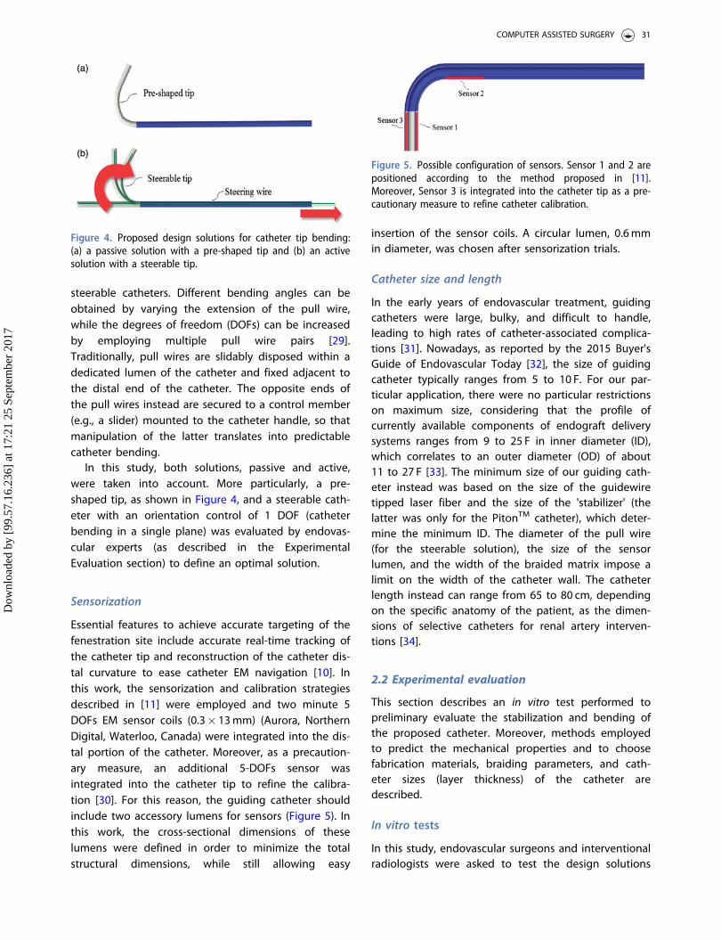
steerable catheters. Different bending angles can beobtained by varying the extension of the pull wire,while the degrees of freedom (DOFs) can be increasedby employing multiple pull wire pairs [29].Traditionally, pull wires are slidably disposed within adedicated lumen of the catheter and fixed adjacent tothe distal end of the catheter. The opposite ends ofthe pull wires instead are secured to a control member(e.g., a slider) mounted to the catheter handle, so thatmanipulation of the latter translates into predictablecatheter bending.
In this study, both solutions, passive and active,were taken into account. More particularly, a pre-shaped tip, as shown in Figure 4, and a steerable cath-eter with an orientation control of 1 DOF (catheterbending in a single plane) was evaluated by endovas-cular experts (as described in the ExperimentalEvaluation section) to define an optimal solution.
Sensorization
Essential features to achieve accurate targeting of thefenestration site include accurate real-time tracking ofthe catheter tip and reconstruction of the catheter dis-tal curvature to ease catheter EM navigation [10]. Inthis work, the sensorization and calibration strategiesdescribed in [11] were employed and two minute 5DOFs EM sensor coils (0.3� 13mm) (Aurora, NorthernDigital, Waterloo, Canada) were integrated into the dis-tal portion of the catheter. Moreover, as a precaution-ary measure, an additional 5-DOFs sensor wasintegrated into the catheter tip to refine the calibra-tion [30]. For this reason, the guiding catheter shouldinclude two accessory lumens for sensors (Figure 5). Inthis work, the cross-sectional dimensions of theselumens were defined in order to minimize the totalstructural dimensions, while still allowing easy
insertion of the sensor coils. A circular lumen, 0.6mmin diameter, was chosen after sensorization trials.
Catheter size and length
In the early years of endovascular treatment, guidingcatheters were large, bulky, and difficult to handle,leading to high rates of catheter-associated complica-tions [31]. Nowadays, as reported by the 2015 Buyer'sGuide of Endovascular Today [32], the size of guidingcatheter typically ranges from 5 to 10 F. For our par-ticular application, there were no particular restrictionson maximum size, considering that the profile ofcurrently available components of endograft deliverysystems ranges from 9 to 25 F in inner diameter (ID),which correlates to an outer diameter (OD) of about11 to 27 F [33]. The minimum size of our guiding cath-eter instead was based on the size of the guidewiretipped laser fiber and the size of the 'stabilizer' (thelatter was only for the PitonTM catheter), which deter-mine the minimum ID. The diameter of the pull wire(for the steerable solution), the size of the sensorlumen, and the width of the braided matrix impose alimit on the width of the catheter wall. The catheterlength instead can range from 65 to 80 cm, dependingon the specific anatomy of the patient, as the dimen-sions of selective catheters for renal artery interven-tions [34].
2.2 Experimental evaluation
This section describes an in vitro test performed topreliminary evaluate the stabilization and bending ofthe proposed catheter. Moreover, methods employedto predict the mechanical properties and to choosefabrication materials, braiding parameters, and cath-eter sizes (layer thickness) of the catheter aredescribed.
In vitro tests
In this study, endovascular surgeons and interventionalradiologists were asked to test the design solutions
Figure 4. Proposed design solutions for catheter tip bending:(a) a passive solution with a pre-shaped tip and (b) an activesolution with a steerable tip.
Figure 5. Possible configuration of sensors. Sensor 1 and 2 arepositioned according to the method proposed in [11].Moreover, Sensor 3 is integrated into the catheter tip as a pre-cautionary measure to refine catheter calibration.
COMPUTER ASSISTED SURGERY 31
Dow
nloa
ded
by [
99.5
7.16
.236
] at
17:
21 2
5 Se
ptem
ber
2017

proposed for catheter stabilization ('Piton-like' vs. 'pre-shaped body') and bending ('over-bent tip' vs. 'steeringtip'). The aim of these tests was to receive preliminaryfeedback from physicians in order to guide the designprocess toward an optimal configuration and to rap-idly and economically test elements that are mostlikely to generate problems related to the differencebetween the perspectives of the designed and user.
Four catheter designs (Figure 6) were tested: designA is a ‘Piton-like’ catheter with a steerable tip; designB is a ‘Piton-like’ catheter with an over-bent tip;design C is a catheter with a pre-shaped body and asteerable tip; and finally design D is a catheter with apre-shaped body and an over-bent tip. All of the cath-eter prototypes were obtained by modifying a 5.5 FOrienter (Angiologica B.M. S.r.l, San Martino SiccomarioPV, Italy), a guiding catheter with a 1 DOF steerabletip [35]. This catheter set, which includes all possiblecombinations of the proposed stabilization and bend-ing systems, was used for a proof of concept demon-stration to assess whether these solutions arereasonable and intuitive for surgeons.
A 300 cm long 0.035’’ LunderquistVR Extra Stiff WireGuide (Cook Medical, Bloomington, IN, USA) was usedas a ‘stabilizer’ for testing of designs A and B.
A diameter of 0.035’’ was chosen according to thePitonTM GC Instructions for Use in order to guaranteesufficient mechanical support. A 0.035’’ RadifocusVR
Guidewire (Terumo Interventional Systems, Somerset,NJ, USA), which has a more flexible distal end, wasinstead used for navigation of design C and Dcatheters.
The in vitro set-up was comprised of a simple aortasimulator, which included an infrarenal aneurysm anda plastic tube, with two fenestration targets, to simu-late the stent graft. The plastic tube is inserted withinthe simulated aneurysm, with targets aligned to therenal ostia (Figure 7). Both the aorta simulator and theplastic tube are composed of clear transparent mater-ial to allow the operator to navigate the catheterunder direct vision.
To assess the different solutions, the operators wereasked to reach the two designated targets within thesimulated aneurysm. More particularly, each operatorwas asked to perform the targeting task both from theright and left femoral access (for a total of 4 targetingprocedures). For analytical purposes, the participantswere divided into three groups on the basis of experi-ence in endovascular procedures. The 'low experience'group consisted of eight subjects who had performed
Figure 6. Preliminary prototypes of the four design solutions to test the stabilization and bending systems. Two pictures arereported for each prototype: a global view of the catheter on the left and a zoom detail of the catheter distal part on the right.The two steerable catheters (Designs A and C) have a handle to actively control bending of the tip.
32 R. PIAZZA ET AL.
Dow
nloa
ded
by [
99.5
7.16
.236
] at
17:
21 2
5 Se
ptem
ber
2017

less than 20 endovascular procedures as the primaryoperator, the 'medium experience' group included fouroperators who had performed between 20 and 100procedures, and finally the 'expert' group consisted ofthree subjects who had performed more than 100endovascular procedures. Before starting the study, allparticipants received the same standardized instruc-tions on in situ fenestration and an explanation ofhow to use each catheter.
At the end of the experimental session, the partici-pants were asked to complete a questionnaire to evalu-ate the four design strategies. The questionnaire wascomprised of 9 items that were assessed using a 5-point Likert scale (1¼ strongly disagree and 5¼ stronglyagree) grouped under two headings: design solutionevaluation and general evaluation of stabilization andbending. The first item group (Table 2) was adminis-tered for each catheter prototype. Then, after evaluationof each design, the participants were asked to expresstheir level of agreement with the general statements(second item group) regarding the stabilization andbending systems (Table 3). Statistical analysis of datawas performed using SPSSVR Statistics Base 19 software(SPSS, Inc., Chicago, IL, USA). The central tendencies ofresponses to a single Likert item were expressed asmedians, with dispersion measured by interquartilerange. The Wilcoxon signed-ranks test was used todetermine the significance of the responses to eachitem to evaluate if the participants were significantlymore likely to agree or disagree with each of the
statements. A probability (p) value<0.05 was consid-ered statistically significant.
In addition to the Likert questionnaire, the opera-tors were also invited to respond to an open questionto address any further comments/observations.
Mechanical properties prediction
CathCADVR , a validated software that includes a com-prehensive material and braid wire database, was usedto test several fabrication materials, braiding parame-ters, and geometries. The employed computationalalgorithms are based on mechanics of compositematerials and composite laminate theory [36,37].Different solutions were analyzed in order to obtaincatheters with variable flexural stiffness (flexibilityincreasing toward the catheter tip), in consideration ofthe rigidity ranges reported in [25] as target values.More specifically, a three-layer braided design wasconsidered and the following plastic materials, com-monly employed for endovascular catheter fabrication,were selected: PellethaneVR 2363 series (LubrizolCorporation, Wickliffe, OH, USA), PebaxVR 33 series(Arkema Inc., Philadelphia, PA, USA), and TEFLONVR
polytetrafluoroethylene (PTFE) (DuPont Corp.,Wilmington, DE, USA).
PellethaneVR 2363 is a thermoplastic polyurethaneelastomer, available at various hardness: 55D and 65Dare the most commonly used shores for medical cath-eters. This material has excellent hydrolytic stability, isresistant to fungi and microorganisms, and has an
Figure 7. In vitro set-up. A global view of the aorta simulator is shown on the left and a zoom detail showing the plastic tubeinserted into the aorta mannequin to simulate the stent graft is shown on the right. Two metal rings are used to indicate the tar-get fenestration sites aligned to the simulated renal ostia (highlighted with blue dotted circles). Note that the plastic tube has noholes at the metal rings.
COMPUTER ASSISTED SURGERY 33
Dow
nloa
ded
by [
99.5
7.16
.236
] at
17:
21 2
5 Se
ptem
ber
2017

exceptionally smooth surface. The coefficient of frictionof PellethaneVR can be further reduced by the additionof hydrophilic polymers, such as polyethyl oxazoline.PebaxVR is a thermoplastic elastomer composed of rigidpolyamide blocks and soft polyether blocks. Its com-position (the block types and ratios) can be varied toachieve a wide range of mechanical properties: theflexural modulus range offered by the PebaxVR 33 ser-ies ranges from approximately 10 to 500MPa [38].Finally, TEFLONVR PTFE is the most common liningmaterials for multi-lumen tubing and is often com-bined with an outer jacket composed of PebaxVR
[39–43]. An austenitic non ferromagnetic steel, 304 Vstainless steel, was selected as a braiding material toprevent interference with the EM localization system.More specifically, a braiding configuration with 32
round wires 0.02mm in diameter was selected andvarious braid angles were tested.
The following strategies were considered to finelytune the mechanical properties of the catheter:
� Changing the braiding properties by varying thebraid angle from 20� to 70�.
� Changing the hardness of the employed materials.
For the PebaxVR 33, hardness shore values of 25D,35D, 40D, and 55D were tested. For the PellethaneVR
2363, hardness shore values of 55D and 65D shoreswere considered.
The catheter size and geometry were definedaccording to the surgeon feedback after analysis ofthe in vitro tests results (Figure 8, in the Results
Table 2. Likert Questionnaire: design solution evaluation. For each item, median values with interquartile range (IQR) (25th;75th) relative to the four proposed design solutions are reported.
Low experience Medium experience Expert group Overall
Items Design Median (IQR) p Median (IQR) p Median (IQR) p Median (IQR) p
1. The catheter can be A 4.00 (3.75;4.00) 0.059 4.00 (4.00;4.25) 0.046 4.00 (4.00;4.50) 0.083 4.00 (4.00;4.00) 0.001easily advanced B 4.00 (3.00;4.00) 0.102 4.00 (4.00;4.25) 0.046 4.00 (4.00;4.00) 0.083 4.00 (4.00;4.00) 0.002
C 3.50 (2.75;4.00) 0.414 3.50 (3.00;4.25) 0.157 2.00 (2.00;2.50) 0.157 3.00 (2.50;4.00) 0.527D 2.50 (2.00;3.25) 0.414 3.00 (3.00;3.50) 0.317 2.00 (2.00;2.50) 0.157 3.00 (2.00;3.00) 0.317
2. The catheter can be A 3.00 (2.00;4.00) 1.000 4.00 (4.00;4.00) 0.046 4.00 (3.50;4.00) 0.157 4.00 (3.00;4.00) 0.083easily rotated B 4.00 (3.00;4.00) 0.102 4.00 (3.75;4.00) 0.083 3.00 (3.00;3.50) 0.317 4.00 (3.00;4.00) 0.011
C 2.00 (2.00;3.00) 0.102 250 (2.00;3.50) 0.564 2.00 (2.00;2.00) 0.083 2.00 (2.00;3.00) 0.021D 2.00 (2.00;2.25) 0.059 3.50 (2.75;4.00) 0.564 2.00 (2.00;2.00) 0.083 2.00 (2.00;3.00) 0.052
3. The catheter tip can be A 4.00 (3.75;4.00) 0.014 4.00 (3.75;4.25) 0.083 4.00 (3.50;4.00) 0.157 4.00 (3.50;4.00) 0.001properly guided and B 3.50 (2.75;4.00) 0.414 3.00 (2.75;3.25) 1.000 3.00 (2.50;3.50) 1.000 3.00 (2.50;4.00) 0.527aligned to the targets C 2.50 (2.00;3.25) 0.414 4.00 (2.75;5.00) 0.564 3.00 (2.50;3.50) 1.000 3.00 (2.00;4.00) 0.763
D 2.50 (2.00;3.00) 0.180 2.50 (2.00;3.25) 0.564 2.00 (2.00;2.50) 0.157 2.00 (2.00;3.00) 0.058
4. The catheter can be A 4.00 (3.00;4.00) 0.025 4.50 (3.75;5.00) 0.083 4.00 (3.50;4.50) 0.157 4.00 (3.00;4.00) 0.002maintained in a stable B 3.00 (2.00;4.00) 1.000 2.50 (2.00;3.00) 0.157 4.00(3.00;4.00) 0.564 3.00 (2.00;4.00) 0.763position during fenestration C 3.00 (3.00;4.00) 0.317 4.00 (3.00;5.00) 0.157 3.00 (2.50;3.50) 0.317 3.00 (3.00;4.00) 0.059
D 2.50 (2.00;3.25) 0.414 2.50 (1.75;3.25) 0.564 2.00 (2.00;2.50) 0.157 2.00 (2.00;3.00) 0.132
5. It is possible to reach A 3.00 (2.00;4.00) 1.000 2.00 (2.00;2.25) 0.083 2.00 (2.00;2.50) 0.157 2.00 (2.00;3.50) 0.166both targets without B 2.00 (2.00;3.25) 0.257 2.00 (2.00;2.25) 0.083 2.00 (2.00;3.00) 0.564 2.00 (2.00;3.00) 0.052changing catheter access C 2.00 (2.00;3.00) 0.102 2.00 (1.75;2.75) 0.317 3.00 (3.00;3.50) 0.317 2.00 (2.00;3.00) 0.132
D 2.00 (2.00;2.25) 0.014 2.00 (1.75;2.50) 0.317 3.00 (2.50;3.00) 0.317 2.00 (2.00;3.00) 0.007
6. After the fenestration A 4.00 (3.00;4.25) 0.102 4.00 (3.75;4.25) 0.083 3.00 (3.00;3.50) 0.317 4.00 (3.00;4.00) 0.011procedure, the catheter can B 3.00 (2.75;4.00) 0.655 3.00 (2.75;3.25) 1.000 3.00 (2.50;3.50) 1.000 3.00 (2.50;4.00) 0.739also be used for cannula-tion of the renal
C 2.00 (1.75;2.25) 0.059 3.50 (2.00;5.00) 1.000 3.00 (3.00;3.50) 0.317 2.00 (2.00;3.50) 0.248
arteries D 2.00 (2.00;2.25) 0.014 2.50 (2.00;3.25) 0.564 3.00 (3.00;3.50) 0.317 2.00 (2.00;3.00) 0.058
Bold indicates statistically significant results (p< 0.05).
Table 3. Likert Questionnaire: general evaluation of stabilization and bending. Median values with interquartile range (IQR) (25th;75th) are reported.
Low experience Medium experience Expert group Overall
Items Median (IQR) p Median (IQR) p Median (IQR) p Median (IQR) p
7. The use of a ‘stabilizer’allows stable positioning
4.00 (3.75;4.25) 0.014 4.00 (3.75;4.25) 0.083 4.00 (3.50;4.00) 0.157 4.00 (3.50;4.00) 0.001
8. A pre-shaped catheterbody allows stablepositioning
3.00 (2.75;4.25) 0.655 3.50 (3.50;4.25) 0.157 2.00 (1.50;2.50) 0.157 3.00 (2.50;4.00) 0.739
9. Active bending of thecatheter tip is useful toeasily reach the fenestra-tion target
4.00 (4.00;5.00) 0.005 4.50 (3.75;5.00) 0.083 4.00 (3.50;4.00) 0.157 4.00 (4.00;5.00) 0.000
34 R. PIAZZA ET AL.
Dow
nloa
ded
by [
99.5
7.16
.236
] at
17:
21 2
5 Se
ptem
ber
2017

section, represents two cross sections of the testedcatheter design).
3. Results
The main tendencies (median and interquartile range)of responses to each Likert item are shown in Tables 2and Table 3. Statistically significant results (p< 0.05)are highlighted in bold font.
Based on the overall scores, we conclude thatdesign A, a 'Piton-like' catheter with a steerable tip,was most preferred by the surgeons. As shown inTable 2, there was overall significant agreement thatdesign A allows the catheter to be easily advanced,the catheter tip to be properly guided and aligned tothe target, the catheter to be maintained in a stableposition during fenestration, and the catheter to beused for cannulation of renal arteries after the fenes-tration procedure. Moreover, the obtained data showthat, from the perspective of users, design A alsoallows the catheter to be easily rotated (median score¼4). For this particular design, the overall scores are inagreement with the experts' opinions, with the excep-tion of the score for item 6, for which the expertgroup expressed a neutral opinion about the possibil-ity of also using the catheter for cannulation of therenal arteries. However, a larger study with a greaternumber of experts is required for statistical evidencein this group.
As suggested by the results presented in Table 2,none of the proposed design enabled the user toreach both fenestration targets without changing the
catheter access, which means that only one fenestra-tion will be accessible from a given iliac vessel at onetime. Nevertheless, as pointed out by the expert sur-geons, the possibility of using a unilateral accessshould not be considered a critical feature, since endo-vascular procedures often require a bilateral femoralapproach.
Considerations of design A, emerging from Table 2(item 1:6, design solution evaluation), are confirmedby responses to items 7 and 9 (general evaluation ofstabilization and bending), which are summarized inTable 3. Each group agreed that the use of a 'stabilizer'allows a stable positioning of the catheter and activebending of the catheter tip is useful to easily reachthe fenestration target.
Figure 8 shows possible cross sections at positionsA1, A2, and B of a design A catheter with a 9 F shaft.The proposed catheter is composed of three layersand four lumens: a central operative lumen (I) for theguidewire tipped laser fiber and the 'stabilizer', twolumens for EM sensors (II), and a lumen for the steer-ing cable (III).
The central operative lumen tapers from a diameterof 1.85mm (to accommodate both the guidewiretipped laser fiber and the 'stabilizer') at the proximalend (A1 and A2 cross sections), to a diameter of0.93mm (to accommodate only the guidewire tippedlaser fiber) at the distal end (B cross section).
Given the geometric parameters of the selectedcatheter design, several simulations were performed aspreviously described in the 'Mechanical PropertiesPrediction' paragraph, i.e., changing braiding properties
Figure 8. Possible cross-sectional views ('A1-A1, ' 'A2-A2, ' and 'B-B') at positions A1, A2, and B, of a design A catheter. Four lumensare shown: a central operative lumen (I) for the guidewire tipped laser fiber and the 'stabilizer', two lumens for EM sensors (II),and a lumen for the steering cable (III). The cross section A1-A1 is constant in the catheter blue portion. Then, after the side holefor the 'stabilizer, ' tapering of the central operative lumen (I) as well as the catheter external diameter was started. Two coordin-ate systems (XAYAZ and XBYBZ, respectively) used for calculation of the second moment of area (Ixx, Iyy, Jzz) at 'A1-A1' and 'B-B' arerepresented.
COMPUTER ASSISTED SURGERY 35
Dow
nloa
ded
by [
99.5
7.16
.236
] at
17:
21 2
5 Se
ptem
ber
2017

and layer materials. As shown in Table 4, two solutionswere selected among all of the simulations with flex-ural (EIxx, EIyy), axial (EA) and torsional (GJzz) rigiditiescompatible with the target values in the literature(Table 1).
For both solutions, rigidities values of three por-tions corresponding to sections A1, A2, and B (Figure8) are reported. The area and second moment ofarea (Ixx, Iyy, Jzz) of the inner layer is reportedtogether with the thickness of the reinforcement andouter layers. In the first solution, PTFE is used as alying material and PebaxVR 3335 (35D) is employedfor the reinforcement and outer layers. In the secondsolution, all of the catheter layers are made ofPellethaneVR 2363-55D.
In both solutions, the braiding angle (BA) of thereinforcement layer increases from A1 to A2 (from 50�
to 60�) and from A2 to B (from 60� to 65�) to reducethe flexural rigidity toward the tip side of the catheter.However, despite this braiding angle variation, in thefirst solution, flexural rigidity was greater in section Bthan A1 (see Table 4) because flexural rigidity isdependent on the second moment of area (Equation(2)). The latter indeed increases towards the cathetertip due to the tapering of the central operative lumen.In the second solution, the inner layer is made ofPellethaneVR 2363-55D, which has a lower stiffnessthan TEFLONVR PTFE (flexural modulus equal to 0.172vs. 0.496MPa). Thus, despite the increase in thesecond moment of area, the contribution of the braid-ing angle is sufficient to reduce the flexural modulus.For this reason, the second solution was selected forthe final design of the catheter.
4. Conclusion
This work represents the first step toward the develop-ment of a 3D EM navigation platform for the guidanceof an innovative endovascular procedure to repair anabdominal aortic aneurysm via in situ laser fenestra-tion of a traditional stent graft. The idea behind thiswork is to integrate a laser system into a 3D EM navi-gation platform to provide the surgeon with a select-ive fenestration tool that can be accurately trackedand shown within the 3D model of the patient vascu-lature. This work focuses on the sensorized guidingcatheter for the navigation and positioning of the lasertool in correspondence to the fenestration site. Thesepreliminary results demonstrated the clinical reason-ability and feasibility of the designed tool in terms ofmechanical properties.
Based on the surgeon feedback, a 9 F ‘Piton-like’catheter with a steerable tip was designed.Ta
ble4.
Mechanicalsimulations
fortwodiffe
rent
solutio
ns.
Solutio
n1
Solutio
n2
SectionA 1
SectionA 2
SectionB
SectionA 1
SectionA 2
SectionB
InnerLayer
I xx(m
m4 )
2.03
2.03
2.26
2.03
2.03
2.26
I yy(m
m4 )
1.49
1.49
2.14
1.49
1.49
2.14
J zz(m
m4 )
3.52
3.52
4.40
3.52
3.52
4.40
Area
(mm
2 )2.58
2.58
4.28
2.58
2.58
4.28
Material
PTFE
VRPTFE
VRPTFE
VRPellethaneV
R
2363
(55D
)PellethaneV
R
2363
(55D
)PellethaneV
R
2363
(55D
)Reinforcem
entlayer
Thickness(m
m)
0.05
0.05
0.05
0.05
0.05
0.05
Braiding
Parameter
0.02
mm
rd,2
4BW
,BA
¼50
�0.02
mm
rd,2
4BW
,BA
¼60
�0.02
mm
rd,2
4BW
,BA
¼65
�0.02
mm
rd,2
4BW
,BA
¼50
�0.02
mm
rd,2
4BW
,BA
¼60
�0.02
mm
rd,2
4BW
,BA
¼65
�Material
AISI
304V
AISI
304V
AISI
304V
AISI
304V
AISI
304V
AISI
304V
PebaxVR
3335
(35D
)PebaxVR
3335
(35D
)PebaxVR
3335
(35D
)PellethaneV
R
2363
(55D
)PellethaneV
R
2363
(55D
)PellethaneV
R
2363
(55D
)Outer
layer
Thickness(m
m)
0.05
0.05
0.01
0.05
0.05
0.01
Material
PebaxVR
3335
(35D
)PebaxVR
3335
(35D
)PebaxVR
3335
(35D
)PellethaneV
R
2363
(55D
)PellethaneV
R
2363
(55D
)PellethaneV
R
2363
(55D
)EIxxx-axis(N
m2 )
86710
�6
84610
�6
91010
�6
76010
�6
69410
�6
60310
�6
EIyyy-axis(N
m2 )
65310
�6
63210
�6
86310
�6
69310
�6
62510
�6
59010
�6
EA(N)
1015
991
1587
890
811
1051
GJ zz(N
m2 )
2118
10�6
2112
10�6
1615
10�6
1986
10�6
1995
10�6
1435
10�6
CathCA
Dsimulations
wereperformed
usingmil(a
thou
sand
thof
aninch)as
theun
itmeasure
forthickness.Leng
thsrepo
rted
inthetableareconvertedto
mm
andhave
anapproximationby
defect.The
following
abbreviatio
nsareused:0
.02mm
rd¼roun
dwires0.02
mm
indiam
eter;B
W¼nu
mberof
braiding
wires;BA
¼braiding
angle.
36 R. PIAZZA ET AL.
Dow
nloa
ded
by [
99.5
7.16
.236
] at
17:
21 2
5 Se
ptem
ber
2017
The proposed catheter features a steering cable toactively control the catheter distal curvature, a centraloperative lumen for the laser device and a side holefor the insertion of a 'stabilizer', and 5 DOFs EM coilsfor real-time tracking of the catheter. The availabilityof a steerable guiding catheter will allow the user toplace the laser fiber tip perpendicular to the graft sur-face as required for optimal stent graft fenestration.Moreover, after the fenestration procedure, it couldalso allow to operator to adjust the bending angle toproperly cannulate the collateral artery.
The simulations performed with CathCADVR , a com-mercially available software for catheter design, dem-onstrated the technical feasibility of the proposeddesign in terms of mechanical specifications. Morespecifically, a three-layered braided design, with abraid angle increasing from 50� to 65� toward the tipside of the catheter, was selected to achieve flexural,axial, and torsional rigidities compatible with the tar-get values in the literature. PellethaneVR 2363-55D waschosen as the material to construct the catheter tub-ing and 304 V stainless steel, an austenitic non-ferro-magnetic steel, was selected as a braiding material toprevent electromagnetic interference with the localiza-tion system.
One limitation of this study is the relatively smallnumber of surgeons involved in the trial. However, theaim of this work was to rapidly and economically testelements that are most likely to generate problemsrelated to the difference between the perspectives ofthe user and designer.
In vitro tests were performed using early catheterprototypes and a very simple vascular simulator toreceive a preliminary surgeon feedback regarding theproposed solutions for catheter stabilization andbending.
This study represents the starting point of an itera-tive process with the purpose to guide the designtoward the preferred solutions of the surgeon, whichwill include in vitro tests with improved materials andmore realistic simulators with different anatomical var-iants. The next step will be the manufacturing of cath-eters according to the user feedback and themechanical specifications listed in this work. Futurestudies will include accurate mechanical testing of theobtained catheter according to the methods proposedin the literature [24,25]. In vitro testing, involving alarger number of surgeons and using a simulator witha more realistic anatomical shape, will be performedfor a further validation of the catheter prior to animaltesting [44]. Moreover, simulated blood flow will beconsidered for quantitative evaluation of the catheterstability in a realistic scenario.
Disclosure statement
The authors report no conflicts of interest. The authors aloneare responsible for the content and writing of this article.
Funding
This study was partially funded by the Italian Ministry ofHealth and Regione Toscana, Project Code:D56D12000360001 (Electromagnetic guided in situ laser fen-estration of endovascular endoprosthesis, November2014–November 2017).
References
[1] Crawford ES, Beckett WC, Greer MS. Juxtarenal infra-renal abdominal aortic aneurysm. Special diagnosticand therapeutic considerations. Ann Surg.1986;203:661–670.
[2] Ricotta JJ II, Oderich GS. Fenestrated and branchedstent grafts. Perspect Vasc Surg Endovasc Ther.2008;20:174–187.
[3] Chuter TA. Fenestrated and branched stent-grafts forthoracoabdominal, pararenal and juxtarenal aorticaneurysm repair. Semin Vasc Surg. 2007;20:90–96.
[4] Chuter TA. Branched and fenestrated stent grafts forendovascular repair of thoracic aortic aneurysms.J Vasc Surg. 2006;43(Suppl A):111A–115A.
[5] McWilliams RG, Fearn SJ, Harris PL, et al. Retrograde fen-estration of endoluminal grafts from target vessels: feasi-bility, technique, and potential usage. J Endovasc Ther.2003;10:946–952.
[6] Ahanchi SS, Almaroof B, Stout CL, et al. In situ laserfenestration for revascularization of the left subclavianartery during emergent thoracic endovascular aorticrepair. J Endovasc Ther. 2012;19:226–230.
[7] Lin J, Udgiri N, Guidoin R, et al. In vitro laser aorticand thoracic stent graft fenestration for urgent treat-ment of aortopathies. J Vasc Surg. 2014;60:1398.
[8] Murphy EH, Dimaio JM, Dean W, et al. Endovascularrepair of acute traumatic thoracic aortic transectionwith laser-assisted in-situ fenestration of a stent-graftcovering the left subclavian artery. J Endovasc Ther.2009;16:457–463.
[9] Redlinger RE Jr, Ahanchi SS, Panneton JM. In situ laserfenestration during emergent thoracic endovascularaortic repair is an effective method for left subclavianartery revascularization. J Vasc Surg. 2013;58:1171–1177.
[10] Condino S, Calabro EM, Alberti A, et al. Simultaneoustracking of catheters and guidewires: comparison tostandard fluoroscopic guidance for arterial cannula-tion. Eur J Vasc Endovasc Surg. 2014;47:53–60.
[11] Condino S, Ferrari V, Freschi C, et al. Electromagneticnavigation platform for endovascular surgery: how todevelop sensorized catheters and guidewires. Int JMed Robot Comput Assist Surg. 2012;8:300–310.
[12] Sidhu R, Weir-McCall J, Cochennec F, et al. Evaluationof an electromagnetic 3D navigation system to facili-tate endovascular tasks: a feasibility study. Eur J VascEndovasc Surg. 2012;43:22–29.
COMPUTER ASSISTED SURGERY 37
Dow
nloa
ded
by [
99.5
7.16
.236
] at
17:
21 2
5 Se
ptem
ber
2017

[13] Pujol S, Pecher M, Magne JL, et al. A virtual realitybased navigation system for endovascular surgery.Stud Health Technol Informat. 2004;98:310–312.
[14] Zhang L, Parrini S, Freschi C, et al. 3D ultrasound cen-terline tracking of abdominal vessels for endovascularnavigation. Int J Cars. 2014;9:127–135.
[15] Parrini S, Zhang L, Condino S, et al. Automatic carotidcenterline extraction from three-dimensional ultra-sound Doppler images. Conf Proc IEEE Eng Med BiolSoc. 2014;2014:5089–5092.
[16] Turini G, Condino S, Postorino M, et al. Improvingendovascular intraoperative navigation with real-timeskeleton-based deformation of virtual vascular struc-tures. Augmented reality, virtual reality, and computergraphics: Third International Conference, AVR, Lecce,Italy, June 15-18, Proceedings, Part II; 2016. p. 82–91.
[17] Moore WS, Ahn SS. Endovascular surgery. Philadelphia(PA): Saunders; 2001.
[18] Sonesson B, Dias N, Resch T, et al. Laser GeneratedIn situ Fenestrations in Dacron Stent Grafts. Eur J VascEndovasc Surg. 2016;51:499–503.
[19] Stenqvist O, Curelaru I, Linder LE, et al. Stiffness ofcentral venous catheters. Acta Anaesthesiol Scand.1983;27:153–157.
[20] Bersten AD, Williams DR, Phillips GD. Central venouscatheter stiffness and its relation to vascular perfor-ation. Anaesth Intensive Care. 1988;16:342–351.
[21] Martin RW, Johnson CC. Engineering considerations ofcatheters for intravascular ultrasonic measurements.Proceeding of SPIE, Catheter-Based Sensing andImaging Technology; 1989.
[22] Wunsche P, Werner C, Bloss P. Bending stiffness ofcatheters and guide wires. Biomed Tech Biomed Eng2002;47(Suppl 1):150–153.
[23] Eckmann DM. Variations in epidural catheter manufac-ture: implications for bending and stiffness. RegAnesth Pain Med. 2003;28:37–42.
[24] Carey J, Emery D, McCracken P. Buckling test as anew approach to testing flexural rigidities of angio-graphic catheters. J Biomed Mater Res Part B ApplBiomater. 2006;76:211–218.
[25] Carey J, Fahim A, Munro M. Design of braided com-posite cardiovascular catheters based on requiredaxial, flexural, and torsional rigidities. J Biomed MaterRes. 2004;70:73–81.
[26] Mishra S, Bahl VK. Curriculum in cath lab: coronaryhardware: part I the choice of guiding catheter. IndianHeart J. 2009;61:80–88.
[27] Kocaturk O, Saikus CE, Guttman MA, et al. Whole shaftvisibility and mechanical performance for active MRcatheters using copper-nitinol braided polymer tubes.J Cardiovasc Magn Reson. 2009;11:29.
[28] PitonTM GC [Internet]. Minneapolis (MN): Medtronic.[cited 2017 Feb 15]. Available from: http://www.
peripheral.medtronicendovascular.com/international/product-type/carotid-package/piton-gc/index.htm
[29] Fu YL, Liu H, Huang WT, et al. Steerable catheters inminimally invasive vascular surgery. Int J Med Robot.2009;5:381–391.
[30] Condino S, Piazza R, Micheletti F, et al.Electromagnetic guided in-situ laser fenestration ofendovascular stent-graft: endovascular tools sensoriza-tion strategy and preliminary laser testing. Lect NotesComput Sci. 2016;9805:72–83.
[31] Udaya Prashant P. Current and emerging cathetertechnologies for percutaneous transluminal coronaryangioplasty. Res Rep Clin Cardiol. 2014;5:213–226.
[32] Endovascular Today’s 2015 Buyer’s Guide [Internet].Wayne (PA): Bryn Mawr Communications Ii, Llc. [cited2017 Feb 15]. Available from: http://evtoday.com/buyers-guide/2015/chart.asp?id=guiding_catheters
[33] Arslan B, Turba UC, Sabri S, et al. Current status ofpercutaneous endografting. Semin Intervent Radiol.2009;26:67–73.
[34] Schneider P. Endovascular skills: guidewire and cath-eter skills for endovascular surgery. 2nd ed. BocaRaton (FL): CRC Press; 2003.
[35] Orienter [Internet]. Pavia (Italy): Angiologica B.M. S.r.l.;[cited 2017 Feb 15]. Available from: from: http://www.angiologica.com/catetere-orientabile-orienter.
[36] Jones RM. Mechanics of composite materials. NewYork: Scripta Book Company; 1975.
[37] Richardson D. The fundamental principles of compos-ite material stiffness predictions [Internet]. [cited 2017Feb 15]. Available from: https://sedyono.files.word-press.com/2016/01/property-prediction.pdf.
[38] PebaxVR [Internet]. High Wycombe, Buckinghamshire:RESINEX Group. [cited 2017 Feb 15]. Available from:http://www.resinex.co.uk/products/pebax.html.
[39] Rosenman D, Kayser D, Keleher M, et al. Inventors;Biocardia, Inc., Assignee. Steerable guide cathetersand methods for their use. 2004.
[40] Dinh JQ, Valko JJ, Strauss BM, et al. Inventors; ReverseMedical Corporation, Assignee. Microcatheter withmodified PTFE liner. 2013.
[41] Ross CD. Inventor; Engineering Resources Group In,Assignee. Guide catheter. 2004.
[42] Lentz DC. Inventor; Cook Incorporated, Assignee. Highpressure infusion catheter. 2008.
[43] PTFE Lined Braided Stent Delivery Catheter [Internet].Glens Falls (NY): Precision Extrusion Inc. [cited 2017Feb 15]. Available from: http://www.precisionextru-sion.com/composite_tubing.html
[44] Sinceri S, Carbone M, Marconi M, et al. Basic endovas-cular skills trainer: a surgical simulator for the trainingof novice practitioners of endovascular procedures.Conf Proc IEEE Eng Med Biol Soc. 2015;2015:5102–5105.
38 R. PIAZZA ET AL.
Dow
nloa
ded
by [
99.5
7.16
.236
] at
17:
21 2
5 Se
ptem
ber
2017