design manual m 22-01 revision november 1999€¦ · · 2017-05-05design manual contents november...
TRANSCRIPT

Design Manual ContentsNovember 1999 Page 1
Contents
Date
Division 1 General Information
100 Manual Description September 1992100.01 Purpose100.02 Revisions
110 Nomenclature and References October 1993110.01 Abbreviations110.02 References
120 Systems Planning June 1989120.01 General120.02 Statewide Transportation Planning120.03 Metropolitan Area Transportation Planning120.04 Designation of Highway Routes120.05 State Programs for Local Roads and Streets
130 Systems Data and Services June 1989130.01 Highway Performance Monitoring System130.02 Travel Data and Traffic Analysis130.03 Videologging130.04 Photogrammetry Services
140 Program Development and Federal Aid Financing June 1989140.01 General140.02 Federal Aid Financing
160 General June 1989160.01 Design Principles160.02 Design Standards160.03 Design Items
Division 2 Hearings, Environmental, and Permits
210 Public Involvement and Hearings December 1998210.01 General210.02 Definitions210.03 References210.04 Public Involvement210.05 Hearings210.06 Environmental Hearing210.07 Corridor Hearing210.08 Design Hearing210.09 Access Hearing210.10 Combined Hearings210.11 Administrative Appeal Hearing210.12 Documentation

Contents Design ManualPage 2 November 1999
Date
220 Project Environmental Documentation June 1989220.01 General220.02 Definitions220.03 Project Classification220.04 Class I, EIS220.05 Class II, CE220.06 Class III, EA/Checklist220.07 Project Reevaluation220.08 Project Reviews
240 Permits and Approvals From OtherGovernmental Agencies September 1990240.01 General (240-13 and 14 June 1989)240.02 United States Department of the Army-Corps of Engineers240.03 United States Coast Guard240.04 United States Forest Service240.05 Federal Aviation Administration240.06 FHWA — Western Federal Lands Highway Division240.07 Federal Energy Regulatory Commission240.08 Environmental Protection Agency240.09 Washington State Departments of Fisheries and Wildlife240.10 Washington State Department of Ecology240.11 Washington State Department of Natural Resources240.12 Washington State Department of Labor and Industries240.13 Local Agencies240.14 Utility Agreements
Division 3 Project Documentation
310 Preliminary Studies June 1989310.01 General310.02 Legislative Studies310.03 Route/Design Studies
315 Value Engineering August 1998315.01 General315.02 References315.03 Definitions315.04 Procedures315.05 Documentation
325 Design Matrix Procedures June 1999325.01 General (325-3 through 11 August 1998)325.02 Terminology (325-14 August 1998)325.03 Design Matrix Procedures325.04 Selecting a Design Matrix325.05 Project Type325.06 Using a Design Matrix

Design Manual ContentsNovember 1999 Page 3
Date
330 Design Documentation, Approval, and Process Review June 1999330.01 General (330-1 November 1999)330.02 References (330-2 through 9 June 1999)330.03 Purpose (330-10 through 17 August 1998)330.04 Project Development330.05 Project Definition Phase330.06 Design Documentation330.07 Design Approval330.08 Process Review
Division 4 Project Design Criteria
410 Basic Design Level August 1998410.01 General410.02 Required Safety Items of Work410.03 Minor Safety and Minor Preservation Work
430 Modified Design Level November 1997430.01 General (430-1 through 3 November 1999)430.02 Design Speed (430-4 and 5 December 1998)430.03 Roadway Widths (430-7 April 1998)430.04 Ramp Lane Widths (430-11 August 1998)430.05 Stopping Sight Distance430.06 Profile Grades430.07 Cross Slope430.08 Fill Slopes and Ditch Inslopes430.09 Intersections430.10 Structures
440 Full Design Level December 1998440.01 General (440-9 and 10 November 1999)440.02 References440.03 Definitions440.04 Functional Classification440.05 Terrain Classification440.06 Geometric Design Data440.07 Design Speed440.08 Traffic Lanes440.09 Shoulders440.10 Medians440.11 Parking440.12 Pavement Type440.13 Structure Width440.14 Grades

Contents Design ManualPage 4 November 1999
Date
Division 5 Soils and Paving
510 Investigation of Soils and Surfacing Materials November 1999510.01 General510.02 References510.03 Materials Sources510.04 Geotechnical Investigation, Design, and Reporting510.05 Use of Geotechnical Consultants510.06 Geotechnical Work by Others510.07 Surfacing Report510.08 Documentation
520 Design of Pavement Structure April 1998520.01 Introduction (520-2 and 3 November 1999)520.02 Estimating Tables
530 Geosynthetics April 1998530.01 General (530-13 November 1999)530.02 References530.03 Geosynthetic Type and Characteristics530.04 Geosynthetic Function Definitions and Applications530.05 Design Approach for Geosynthetics530.06 Design Responsibility530.07 Documentation
Division 6 Geometrics
610 Highway Capacity June 1989610.01 General610.02 Definitions and Symbols610.03 Design
620 Geometric Plan Elements April 1998620.01 General (620-1 and 4 November 1999)620.02 References620.03 Definitions620.04 Horizontal Alignment620.05 Distribution Facilities620.06 Number of Lanes and Arrangement620.07 Pavement Transitions620.08 Documentation
630 Geometric Profile Elements April 1998630.01 General630.02 References630.03 Vertical Alignment630.04 Coordination of Vertical and Horizontal Alignments630.05 Airport Clearance630.06 Railroad Crossings630.07 Procedures630.08 Documentation

Design Manual ContentsNovember 1999 Page 5
Date
640 Geometric Cross Section December 1998640.01 General (640-3, 22, 28, 29, 31, and 32 June 1999)640.02 References (640-30, 33, and 34 November 1999)640.03 Definitions640.04 Roadways640.05 Superelevation640.06 Median and Outer Separations640.07 Roadsides640.08 Roadway Sections640.09 Documentation
650 Sight Distance April 1998650.01 General (650-3 June 1999)650.02 References (650-4 November 1999)650.03 Definitions (650-8 and 9 August 1998)650.04 Passing Sight Distance650.05 Stopping Sight Distance650.06 Decision Sight Distance
Division 7 Roadside Safety Elements
700 Roadside Safety August 1997700.01 General (700-3 April 1998)700.02 References (700-8 June 1999)700.03 Definitions700.04 Clear Zone700.05 Hazards to be Considered for Mitigation700.06 Median Considerations700.07 Other Roadside Safety Features700.08 Documentation
710 Traffic Barriers November 1997710.01 General (710-2 August 1998)710.02 References (710-4 through 6, 17, and 19 December 1998)710.03 Definitions (710-7 November 1999)710.04 Project Requirements (710-9 and 710-21 April 1998)710.05 Barrier Design710.06 Beam Guardrail710.07 Cable Barrier710.08 Concrete Barrier710.09 Redirectional Land Forms710.10 Bridge Rails710.11 Other Barriers710.12 Documentation
720 Impact Attenuator Systems June 1999720.01 Impact Attenuator Systems720.02 Design Criteria720.03 Selection720.04 Documentation

Contents Design ManualPage 6 November 1999
Date
Division 8 Traffic Safety Elements
810 Construction Work Zone Traffic Control Strategy December 1994810.01 General810.02 References810.03 Definitions810.04 Construction Work Zone Traffic Control Strategy810.05 Procedures
820 Signing November 1999820.01 General820.02 References820.03 Design Components820.04 Overhead Installation820.05 Mileposts820.06 Guide Sign Plan820.07 Documentation
830 Delineation September 1992830.01 General (830-5 through 7 March 1994)830.02 Pavement Marking830.03 Raised Pavement Markers830.04 Guideposts830.05 Barrier Delineation830.06 Wildlife Warning Reflectors830.07 Procedure
840 Illumination March 1991840.01 General (840-5 and 6 June 1989)840.02 References (840-4 and 7 March 1994)840.03 Definitions840.04 Approval Requirements840.05 Warrants840.06 Design Report
850 Traffic Control Signals June 1989850.01 General (850-1 September 1990)850.02 Policy (850-13, 16 through 21, 29 through 38 March 1994)850.03 Approval Requirements850.04 Signal Design850.05 Contract Preparation
860 Intelligent Transportation Systems November 1999860.01 General860.02 References860.03 Traffic Data Collection860.04 Traffic Flow Control860.05 Motorist Information860.06 Documentation

Design Manual ContentsNovember 1999 Page 7
Date
Division 9 Interchanges and Intersections
910 Intersections at Grade August 1997910.01 General (910-1 through 3 August 1998)910.02 References (910-17 through 19 November 1999)910.03 Definitions (910-21 through 24 November 1999)910.04 Design Considerations (910-21 and 25 April 1998)910.05 Design Vehicle (910-26 December 1998)910.06 Right-Turn Corners (910-33, 34, and 36 November 1999)910.07 Channelization910.08 Roundabouts910.09 U-Turns910.10 Sight Distance at Intersections910.11 Traffic Control at Intersections910.12 Interchange Ramp Terminals910.13 Procedures910.14 Documentation
920 Road Approaches April 1998920.01 General (920-5, 6, 8, and 9 November 1999)920.02 References920.03 Definitions920.04 Design Considerations920.05 Road Approach Connection Category920.06 Road Approach Design Template920.07 Sight Distance920.08 Road Approach Spacing and Corner Clearance920.09 Drainage Requirements920.10 Procedures920.11 Documentation
930 Railroad Grade Crossings June 1989930.01 General (930-4, 6 through 12 March 1994)930.02 References930.03 Plans930.04 Traffic Control Systems930.05 Stopping Lanes930.06 Types of Crossing Surfaces930.07 Crossing Closure930.08 Traffic Controls During Construction and Maintenance930.09 Railroad Grade Crossing Orders930.10 Longitudinal Easements From Railroad

Contents Design ManualPage 8 November 1999
Date
940 Traffic Interchanges June 1999940-01 General (940-5, 10, 17 through 20 November 1999)940.02 References (940-23 through 27, and 29 November 1999)940.03 Definitions940.04 Interchange Design940.05 Ramps940.06 Interchange Connections940.07 Ramp Terminal Intersection at Crossroads940.08 Interchanges on Two-Lane Highways940.09 Interchange Plans940.10 Documentation
960 Median Crossovers August 1997960.01 General960.02 Analysis960.03 Design960.04 Approval960.05 Documentation
Division 10 Auxiliary Facilities
1010 Auxiliary Lanes November 19991010.01 General1010.02 References1010.03 Definitions1010.04 Climbing Lanes1010.05 Passing Lanes1010.06 Slow Moving Vehicle Turnouts1010.07 Shoulder Driving for Slow Vehicles1010.08 Emergency Escape Ramps1010.09 Chain-Up Areas1010.10 Documentation
1020 Facilities for Nonmotorized Transportation June 19891020.01 General (1020-6 March 1991)1020.02 Definitions (1020-9 and 10 October 1995)1020.03 Bicycle Facilities (1020-11 through 19 March 1994)1020.04 Pedestrian Facilities (1020-21 through 40 March 1994)
(Walkways)1020.05 Equestrian and Watercraft Facilities
1030 Safety Rest Areas and Travel Services June 19991030.01 General (1030-3 through 5 November 1999)1030.02 References1030.03 Documentation

Design Manual ContentsNovember 1999 Page 9
Date
1040 Weigh Stations June 19891040.01 General (1040-3 through 14 March 1994)1040.02 Planning and Development1040.03 Permanent Facilities1040.04 Portable Facilities1040.05 Agency Responsibilities1040.06 Design Report1040.07 Federal Aid Participation
1050 High Occupancy Vehicle Priority Treatment June 19951050.01 General1050.02 Definitions1050.03 References1050.04 Preliminary Design and Planning1050.05 HOV Operations1050.06 Design Criteria1050.07 Arterial HOV
1060 Transit Benefit Facilities December 19911060.01 Introduction (1060-14 March 1994)1060.02 Definitions (1060-16 through 22 March 1994)
(1060-19 November 1997)1060.03 Park and Ride Lots (1060-23 and 24 July 1994)1060.04 Transfer/Transit Centers (1060-25 through 34 March 1994)1060.05 Bus Stop and Pullouts (1060-35 and 36 July 1994)1060.06 Passenger Amenities (1060-37 and 38 March 1994)1060.07 Roadway and Vehicle Design Criteria Characteristics1060.08 Intersection Radii1060.09 Disabled Accessibility1060.10 References
Division 11 Structures
1110 Site Data for Structures April 19981110.01 General (1110-3 through 5 November 1999)1110.02 References1110.03 Required Data for All Structures1110.04 Additional Data for Waterway Crossings1110.05 Additional Data for Grade Separations1110.06 Additional Data for Widenings1110.07 Documentation
1120 Bridges December 19981120.01 General1120.02 References1120.03 Bridge Location1120.04 Bridge Site Design Elements1120.05 Documentation

Contents Design ManualPage 10 November 1999
Date
1130 Retaining Walls December 19981130.01 References (1130-1 November 1999)1130.02 General (1130-12 November 1999)1130.03 Design Principles1130.04 Design Requirements1130.05 Guidelines for Wall/Slope Selection1130.06 Design Responsibility and Process1130.07 Documentation
1140 Noise Barriers December 19981140.01 General1140.02 References1140.03 Design1140.04 Procedures1140.05 Documentation
Division 12 Hydraulics
1210 Hydraulic Design December 19981210.01 General1210.02 References1210.03 Hydraulic Considerations1210.04 Safety Considerations1210.05 Design Responsibility
Division 13 Roadside Development
1300 Roadside Development and Highway Beautification June 19991300.01 General1300.02 References1300.03 Roadside Classification Plan1300.04 Roadside Manual1300.05 Design Requirements1300.06 Documentation1300.07 Design Recommendations
1310 Contour Grading June 19991310.01 General1310.02 References1310.03 Procedures1310.04 Recommendations
1320 Vegetation June 19991320.01 General1320.02 References1320.03 Discussion1320.04 Recommendations1320.05 Design Guidelines1320.06 Documentation

Design Manual ContentsNovember 1999 Page 11
Date
1330 Irrigation June 19991330.01 General1330.02 References1330.03 Design Considerations
1350 Soil Bioengineering August 19971350.01 General1350.02 References1350.03 Uses1350.04 Design Responsibilities and Considerations1350.05 Documentation
Division 14 Right of Way and Access Control
1410 Right of Way Considerations June 19991410.01 General1410.02 References1410.03 Special Features1410.04 Easement and Permit1410.05 Programming for Funds1410.06 Appraisal and Acquisition1410.07 Transactions1410.08 Documentation
1420 Access Control Design Policy June 19891420.01 General (1420-4 March 1994)1420.02 Full Access Control Criteria (1420-11 through 21 March 1994)1420.03 Partial Access Control Criteria1420.04 Modified Access Control Criteria1420.05 Access Approaches1420.06 Approaches Between Limited Access
Highways and Adjacent Railroads1420.07 Frontage Roads1420.08 Multiple Use of Right of Way for Nonhighway Purposes1420.09 Modifications to Established Limited Access Plans
1425 Access Point Decision Report April 19981425.01 General1425.02 Access Point Decision Report and Supporting Analyses1425.03 Procedures1425.04 Documentation
1430 Development of Access Control June 19891430.01 General1430.02 Access Report1430.03 Access Hearing

Contents Design ManualPage 12 November 1999
Date
1440 Surveying and Mapping June 19991440.01 General1440.02 References1440.03 Procedures1440.04 Datums1440.05 Global Positioning System1440.06 WSDOT Monument Database1440.07 Geographic Information System1440.08 Photogrammetric Surveys1440.09 Documentation
1450 Monumentation October 19951450.01 General1450.02 References1450.03 Definitions1450.04 Control Monuments1450.05 Alignment1450.06 Property Corners1450.07 Other Monuments1450.08 Documentation1450.09 Filing Requirements
1460 Fencing June 19991460.01 General1460.02 References1460.03 Design Criteria1460.04 Fencing Types1460.05 Gates1460.06 Procedure1460.07 Documentation
Index November 1999

Design Manual ContentsNovember 1999 Page 13
Figures
FigureNumber Title Page Last Date
210-1 Sequence for a Hearing 210-16 December 1998220-1 Environmental Process Flow Chart 220-14 June 1989240-1a Permits and Approvals 240-11 September 1990240-1b Permits and Approvals 240-12 September 1990240-2 FAA Notice Requirement Related to Highways 240-13 June 1989240-3 DNR Area Management Units 240-14 June 1989
310-1 Legislative Study Cost Estimate 310-6 June 1989310-2 Legislative Study Report Cover 310-7 June 1989310-3 Legislative Study Report Title Page 310-8 June 1989315-1 Eight-Phase Job Plan for VE Studies 315-5 August 1998315-2 Request for Value Engineering Study 315-6 August 1998315-3 VE Study Team Tools 315-7 August 1998325-1 Design Matrix Selection Guide 325-4 August 1998325-2a NHS Highways in Washington 325-6 August 1998325-2b NHS Highways in Washington (continued) 325-7 August 1998325-3a Preservation Program 325-8 August 1998325-3b Improvement Program 325-9 August 1998325-3c Improvement Program (continued) 325-10 August 1998325-4 Design Matrix 1 — Interstate Routes (Main Line) 325-11 August 1998325-5 Design Matrix 2 — Interstate Interchange Areas 325-12 June 1999325-6 Design Matrix 3 — NHS Routes (Main Line) 325-13 June 1999325-7 Design Matrix 4 — Non-Interstate Interchange Areas 325-14 August 1998325-8 Design Matrix 5 — Non-NHS Routes 325-15 June 1999330-1 Design Approval Level 330-6 June 1999330-2 Reviews and Approvals 330-7 June 1999330-3a Reviews and Approvals, Design 330-8 June 1999330-3b Reviews and Approvals, Design (continued) 330-9 June 1999330-4 PS&E Process Approvals 330-10 August 1998330-5a Sample Project Analysis 330-11 August 1998330-5b Sample Project Analysis 330-12 August 1998330-6 Sample Evaluate Upgrade (EU) 330-13 August 1998

Contents Design ManualPage 14 November 1999
FigureNumber Title Page Last Date
330-7a Sample Deviation, Rural 330-14 August 1998330-7b Sample Deviation, Rural 330-15 August 1998330-8a Sample Deviation, Urban 330-16 August 1998330-8b Sample Deviation, Urban 330-17 August 1998
430-1 Turning Ramp Lane Widths Modified Design Level 430-1 November 1999430-2 Design Vehicles Modified Design Level 430-3 November 1999430-3 Modified Design Level for Multilane Highways and Bridges 430-4 December 1998430-4 Modified Design Level for Two-Lane Highways and Bridges 430-5 December 1998430-5 Minimum Total Roadway Widths for Two-Lane
Highway Curves 430-6 November 1997430-6 Minimum Total Roadway Widths for Two-Lane
Highway Curves, ∆<90˚ — Modified Design Level 430-7 April 1998430-7 Evaluation for Stopping Sight Distance for Crest Vertical
Curves — Modified Design Level 430-8 November 1997430-8 Evaluation for Stopping Sight Distance for Horizontal
Curves — Modified Design Level 430-9 November 1997430-9 Main Line Roadway Sections — Modified Design Level 430-10 November 1997430-10 Ramp Roadway Sections — Modified Design Level 430-11 August 1998440-1 Desirable Design Speed 440-4 December 1998440-2 Minimum Shoulder Width 440-5 December 1998440-3 Geometric Design Data, Interstate 440-7 December 1998440-4a Geometric Design Data, Principle Arterial 440-8 December 1998440-4b Geometric Design Data, Principle Arterial 440-9 November 1999440-5a Geometric Design Data, Minor Arterial 440-10 November 1999440-5b Geometric Design Data, Minor Arterial 440-11 December 1998440-6a Geometric Design Data, Collector 440-12 December 1998440-6b Geometric Design Data, Collector 440-13 December 1998
510-1 Material Source Development Plan 510-16 November 1999520-1 Estimating — Miscellaneous Tables 520-2 November 1999520-2a Estimating — Asphalt Concrete Pavement and Asphalt
Distribution Tables 520-3 November 1999520-2b Estimating — Asphalt Concrete Pavement and Asphalt
Distribution Tables 520-4 April 1998520-3 Estimating — Bituminous Surface Treatment 520-5 April 1998520-4 Estimating — Base and Surfacing Typical Section
Formulae and Example 520-6 April 1998520-5a Estimating — Base and Surfacing Quantities 520-7 April 1998520-5b Estimating — Base and Surfacing Quantities 520-8 April 1998520-5c Estimating — Base and Surfacing Quantities 520-9 April 1998520-5d Estimating — Base and Surfacing Quantities 520-10 April 1998520-5e Estimating — Base and Surfacing Quantities 520-11 April 1998520-5f Estimating — Base and Surfacing Quantities 520-12 April 1998520-5g Estimating — Base and Surfacing Quantities 520-13 April 1998520-5h Estimating — Base and Surfacing Quantities 520-14 April 1998
Design Manual ContentsNovember 1999 Page 15
FigureNumber Title Page Last Date
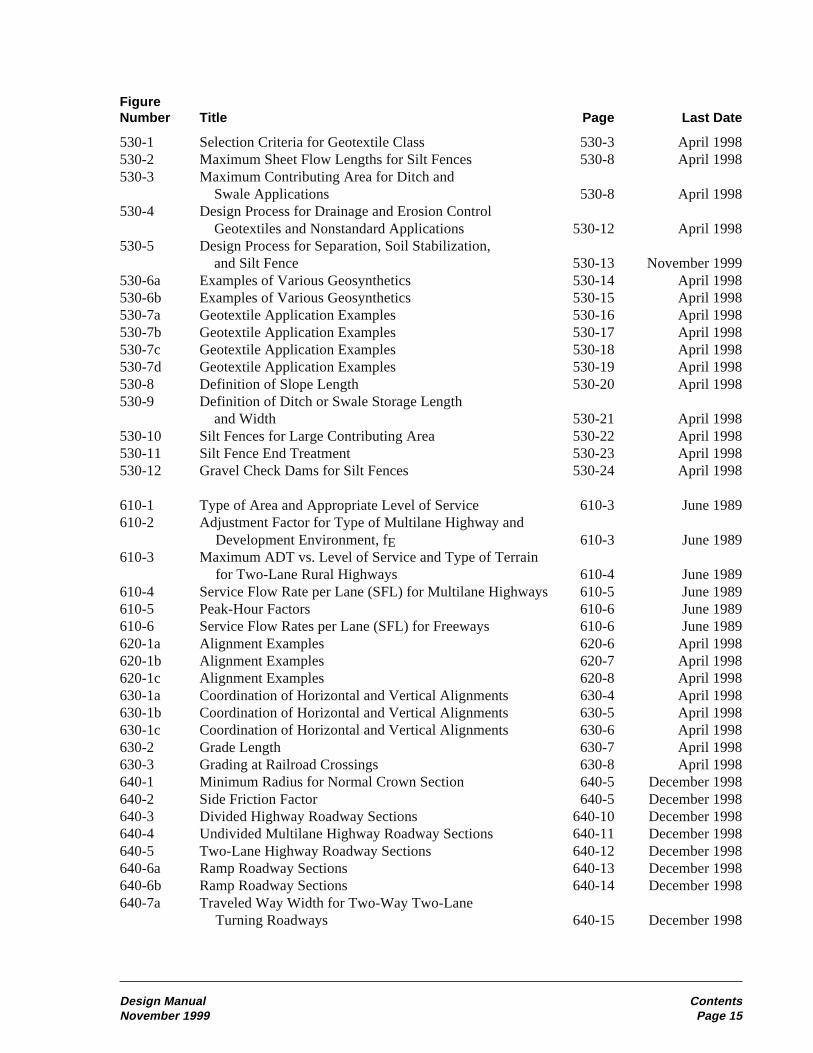
530-1 Selection Criteria for Geotextile Class 530-3 April 1998530-2 Maximum Sheet Flow Lengths for Silt Fences 530-8 April 1998530-3 Maximum Contributing Area for Ditch and
Swale Applications 530-8 April 1998530-4 Design Process for Drainage and Erosion Control
Geotextiles and Nonstandard Applications 530-12 April 1998530-5 Design Process for Separation, Soil Stabilization,
and Silt Fence 530-13 November 1999530-6a Examples of Various Geosynthetics 530-14 April 1998530-6b Examples of Various Geosynthetics 530-15 April 1998530-7a Geotextile Application Examples 530-16 April 1998530-7b Geotextile Application Examples 530-17 April 1998530-7c Geotextile Application Examples 530-18 April 1998530-7d Geotextile Application Examples 530-19 April 1998530-8 Definition of Slope Length 530-20 April 1998530-9 Definition of Ditch or Swale Storage Length
and Width 530-21 April 1998530-10 Silt Fences for Large Contributing Area 530-22 April 1998530-11 Silt Fence End Treatment 530-23 April 1998530-12 Gravel Check Dams for Silt Fences 530-24 April 1998
610-1 Type of Area and Appropriate Level of Service 610-3 June 1989610-2 Adjustment Factor for Type of Multilane Highway and
Development Environment, fE 610-3 June 1989610-3 Maximum ADT vs. Level of Service and Type of Terrain
for Two-Lane Rural Highways 610-4 June 1989610-4 Service Flow Rate per Lane (SFL) for Multilane Highways 610-5 June 1989610-5 Peak-Hour Factors 610-6 June 1989610-6 Service Flow Rates per Lane (SFL) for Freeways 610-6 June 1989620-1a Alignment Examples 620-6 April 1998620-1b Alignment Examples 620-7 April 1998620-1c Alignment Examples 620-8 April 1998630-1a Coordination of Horizontal and Vertical Alignments 630-4 April 1998630-1b Coordination of Horizontal and Vertical Alignments 630-5 April 1998630-1c Coordination of Horizontal and Vertical Alignments 630-6 April 1998630-2 Grade Length 630-7 April 1998630-3 Grading at Railroad Crossings 630-8 April 1998640-1 Minimum Radius for Normal Crown Section 640-5 December 1998640-2 Side Friction Factor 640-5 December 1998640-3 Divided Highway Roadway Sections 640-10 December 1998640-4 Undivided Multilane Highway Roadway Sections 640-11 December 1998640-5 Two-Lane Highway Roadway Sections 640-12 December 1998640-6a Ramp Roadway Sections 640-13 December 1998640-6b Ramp Roadway Sections 640-14 December 1998640-7a Traveled Way Width for Two-Way Two-Lane
Turning Roadways 640-15 December 1998

Contents Design ManualPage 16 November 1999
FigureNumber Title Page Last Date
640-7b Traveled Way Width for Two-Way Two-LaneTurning Roadways 640-16 December 1998
640-8a Traveled Way Width for Two-Lane One-WayTurning Roadways 640-17 December 1998
640-8b Traveled Way Width for Two-Lane One-WayTurning Roadways 640-18 December 1998
640-9a Traveled Way Width for One-Lane Turning Roadways 640-19 December 1998640-9b Traveled Way Width for One-Lane Turning Roadways 640-20 December 1998640-9c Traveled Way Width for One-Lane Turning Roadways 640-21 December 1998640-10a Shoulder Details 640-22 June 1999640-10b Shoulder Details 640-23 December 1998640-11a Superelevation Rates (10% Max) 640-24 December 1998640-11b Superelevation Rates (6% Max) 640-25 December 1998640-11c Superelevation Rates (8% Max) 640-26 December 1998640-12 Superelevation Rates for Turning Roadways
at Intersections 640-27 December 1998640-13a Superelevation Transitions for Highway Curves 640-28 June 1999640-13b Superelevation Transitions for Highway Curves 640-29 June 1999640-13c Superelevation Transitions for Highway Curves 640-30 November 1999640-13d Superelevation Transitions for Highway Curves 640-31 June 1999640-13e Superelevation Transitions for Highway Curves 640-32 June 1999640-14a Superelevation Transitions for Ramp Curves 640-33 November 1999640-14b Superelevation Transitions for Ramp Curves 640-34 November 1999640-15a Divided Highway Median Sections 640-35 December 1998640-15b Divided Highway Median Sections 640-36 December 1998640-15c Divided Highway Median Sections 640-37 December 1998640-16a Roadway Sections in Rock Cuts Design A 640-38 December 1998640-16b Roadway Sections in Rock Cuts Design B 640-39 December 1998640-17 Roadway Sections With Stepped Slopes 640-40 December 1998640-18a Bridge End Slopes 640-41 December 1998640-18b Bridge End Slopes 640-42 December 1998650-1 Passing Sign Distance 650-1 April 1998650-2 Design Stopping Sight Distance 650-3 June 1999650-3 Existing Stopping Sight Distance 650-3 June 1999650-4 Design Stopping Sight Distance on Grades 650-3 June 1999650-5 Decision Sight Distance 650-5 April 1998650-6 Passing Sight Distance for Crest Vertical Curves 650-6 April 1998650-7 Stopping Sight Distance for Crest Vertical Curves 650-7 April 1998650-8 Stopping Sight Distance for Sag Vertical Curves 650-8 August 1998650-9 Horizontal Stopping Sight Distance 650-9 August 1998
700-1 Design Clear Zone Distance Table 700-8 June 1999700-2 Design Clear Zone Inventory Form 700-9 August 1997700-3 Recovery Area 700-11 August 1997700-4 Design Clear Zone for Ditch Sections 700-12 August 1997700-5 Guidelines for Embankment Barrier 700-13 August 1997700-6 Mailbox Location and Turnout Design 700-14 August 1997

Design Manual ContentsNovember 1999 Page 17
FigureNumber Title Page Last Date
700-7 Warrants for Median Barrier 700-15 August 1997700-8 Glare Screens 700-16 August 1997710-1 Type 7 Bridge Rail Upgrade Criteria 710-2 August 1998710-2 Longitudinal Barrier Deflection 710-3 November 1997710-3 Longitudinal Barrier Flare Rates 710-4 December 1998710-4 Guardrail Locations on Slopes 710-5 December 1998710-5 Old Type 3 Anchor 710-7 November 1999710-6 Guardrail Connections 710-8 November 1997710-7 Transitions and Connections 710-9 April 1998710-8 Concrete Barrier Shapes 710-11 November 1997710-9 Single Slope Concrete Barrier 710-12 November 1997710-10 Safety Shaped Concrete Bridge Rail Retrofit 710-14 November 1997710-11a Barrier Length of Need 710-16 November 1997710-11b Barrier Length of Need 710-17 December 1998710-12 Beam Guardrail Post Installation 710-18 November 1997710-13 Beam Guardrail Terminals 710-19 December 1998710-14 Cable Barrier Locations on Slopes 710-20 November 1997710-15 Thrie Beam Bridge Rail Retrofit Criteria 710-21 April 1998720-1 Impact Attenuator Sizes 720-4 June 1999720-2a Impact Attenuator Systems Permanent Installations 720-6 June 1999720-2b Impact Attenuator Systems Permanent Installations 720-7 June 1999720-2c Impact Attenuator Systems Permanent Installations 720-8 June 1999720-3 Impact Attenuator Systems Work Zone Installations 720-9 June 1999720-4a Impact Attenuator Systems — Older Systems 720-10 June 1999720-4b Impact Attenuator Systems — Older Systems 720-11 June 1999720-3 Impact Attenuator Comparison 720-12 June 1999
820-1a Sign Support Locations 820-5 November 1999820-1b Sign Support Locations 820-6 November 1999820-2 Wood Posts 820-7 November 1999820-3 Steel Posts 820-8 November 1999820-4 Laminated Wood Box Posts 820-9 November 1999830-1 Guidepost Requirements 830-3 September 1992830-2 M Spacing of Wildlife Reflectors 830-5 March 1994830-2 Spacing of Wildlife Reflectors 830-7 March 1994840-1 M Basic Illumination Applications 840-4 March 1994840-2 Basic Illumination Applications 840-5 June 1989840-3 Basic Illumination Applications 840-6 June 1989840-1 Basic Illumination Applications 840-7 March 1994850-1 Responsibility for Various Types of Facilities on
State Highways 850-12 June 1989850-2 M Example Optimum Cycle and Split Calculation 850-13 March 1994850-3 Controller Frame Configurations 850-14 June 1989850-4 Control Application Variations 850-15 June 1989850-5a M Signal Displays 850-16 March 1994850-5b M Signal Displays 850-17 March 1994

Contents Design ManualPage 18 November 1999
FigureNumber Title Page Last Date
850-6a M Strain Pole and Foundation Selection Procedure 850-18 March 1994850-6b M Strain Pole and Foundation Selection Example 850-19 March 1994850-7 M Conduit 850-20 March 1994850-8 M Example Signal Plan 850-21 March 1994850-9 Standard Intersection Movements and Head Numbers 850-22 June 1989850-10a Typical Phase Sequence Diagrams 850-23 June 1989850-10b Typical Phase Sequence Diagrams 850-24 June 1989850-10c Typical Phase Sequence Diagrams 850-25 June 1989850-10d Typical Phase Sequence Diagrams 850-26 June 1989850-11 Signal Sequence Chart 850-27 June 1989850-12 Typical Wiring Schematic 850-28 June 1989850-13 M Typical Signal Standard Detail Chart 850-29 March 1994850-2 Example Optimum Cycle and Split Calculation 850-31 March 1994850-5a Signal Displays 850-32 March 1994850-5b Signal Displays 850-33 March 1994850-6a Strain Pole and Foundation Selection Procedure 850-34 March 1994850-6b Strain Pole and Foundation Selection Example 850-35 March 1994850-7 Conduit 850-36 March 1994850-8 Example Signal Plan 850-37 March 1994850-13 Typical Signal Standard Detail Chart 850-38 March 1994
910-1 Design Vehicle Types 910-3 August 1998910-2 Intersection Design Vehicle 910-3 August 1998910-3 Shy Distance for Barrier Curb 910-7 August 1997910-4 U-Turn Spacing 910-9 August 1997910-5 Sight Distance for Turning Vehicles 910-10 August 1997910-6a M Turning Path Template 910-13 August 1997910-6b M Turning Path Template 910-14 August 1997910-7 M Right-Turn Corner 910-15 August 1997910-8 M Left-Turn Storage Guidelines 910-16 August 1997910-9a Left-Turn Storage Length 910-17 November 1999910-9b Left-Turn Storage Length 910-18 November 1999910-9c Left-Turn Storage Length 910-19 November 1999910-9d M Additional Left-Turn Storage for Trucks 910-20 August 1997910-10a Channelization Widening 910-21 November 1999910-10b Median Channelization — Median Width 7 m to 8 m 910-22 November 1999910-10c Median Channelization — Median Width of More Than 8 m 910-23 November 1999910-10d Minor Intersection on Divided Highway 910-24 November 1999910-10e M Two-Way Left-Turn Lane 910-25 April 1998910-11 M Right-Turn Lane Guidelines 910-26 December 1998910-12a M Right-Turn Pocket and Right-Turn Taper 910-27 August 1997910-12b M Right-Turn Lane 910-28 August 1997910-13 M Acceleration Lane 910-29 August 1997910-14a M Traffic Island Designs 910-30 August 1997910-14b M Traffic Island Designs 910-31 August 1997910-14c M Traffic Island Designs 910-32 August 1997910-15 U-Turn Locations 910-33 November 1999

Design Manual ContentsNovember 1999 Page 19
FigureNumber Title Page Last Date
910-16a Sight Distance for Grade Intersection With Stop Control 910-34 November 1999910-16b Sight Distance for Grade Intersection With Stop Control 910-35 August 1997910-16c Sight Distance at Intersections 910-36 November 1999910-17 Interchange Ramp Terminals 910-37 August 1997920-1 Road Approach Design Templates 920-3 April 1998920-2 Minimum Corner Clearance 920-4 April 1998920-3 Noncommercial Approach Design Template A 920-5 November 1999920-4 Noncommercial Approach Design Template B and C 920-6 November 1999920-5 Commercial Approach — Single Approach
Design Template D 920-7 April 1998920-6 Road Approach Sight Distance 920-8 November 1999920-7 Road Approach Spacing and Corner Clearance 920-9 November 1999930-1 M Sight Distance at Railroad Crossing 930-4 March 1994930-2 Guidelines for Railroad Crossing Protection 930-5 June 1994930-3 M Typical Pullout Lane at Railroad Crossing 930-6 March 1994930-4 M Railroad Crossing Plan for Washington Utilities and
Transportation Commission 930-7 March 1994930-5 M Longitudinal Easement Cross Sections 930-8 March 1994930-1 Sight Distance at Railroad Crossing 930-9 March 1994930-3 Typical Pullout Lane at Railroad Crossing 930-10 March 1994930-4 Railroad Crossing Plan for Washington Utilities and
Transportation Commission 930-11 March 1994930-5 Longitudinal Easement Cross Sections 930-12 March 1994940-1 Ramp Design Speed 940-4 June 1999940-2 Maximum Ramp Grade 940-5 November 1999940-3 Ramp Widths 940-5 November 1999940-4 Basic Interchange Patterns 940-11 June 1999940-5 Minimum Ramp Terminal Spacing 940-12 June 1999940-6a Lane Balance 940-13 June 1999940-6b Lane Balance 940-14 June 1999940-7 Main Line Lane Reduction Alternatives 940-15 June 1999940-8 Acceleration Lane Length 940-16 June 1999940-9a On-Connection (Single-Lane, Taper Type) 940-17 November 1999940-9b On-Connection (Single-Lane, Parallel Type) 940-18 November 1999940-9c On-Connection (Two-Lane, Parallel Type) 940-19 November 1999940-9d On-Connection (Two-Lane, Taper Type) 940-20 November 1999940-10 Deceleration Lane Length 940-21 June 1999940-11 Gore Area Characteristics 940-22 June 1999940-12a Off-Connection (Single Lane, Taper Type) 940-23 November 1999940-12b Off-Connection (Single Lane, Parallel Type) 940-24 November 1999940-12c Off-Connection (Single-Lane, One Lane Reduction 940-25 November 1999940-12d Off-Connection (Two-Lane, Taper Type) 940-26 November 1999940-12e Off-Connection (Two-Lane, Parallel Type) 940-27 November 1999940-13a Collector Distributor (Outer Separations) 940-28 June 1999940-13b Collector Distributor (Off-Connections) 940-29 November 1999940-13c Collector Distributor (On-Connections) 940-30 June 1999940-14 Loop Ramps Connections 940-31 June 1999

Contents Design ManualPage 20 November 1999
FigureNumber Title Page Last Date
940-15 Length of Weaving Sections 940-32 June 1999940-16 Temporary Ramps 940-33 June 1999940-17 Interchange Plan 940-34 June 1999
1010-1 Rolling Resistance 1010-4 November 19991010-2a Performance for Heavy Trucks 1010-6 November 19991010-2b Speed Reduction Example 1010-7 November 19991010-3 Level of Service — Multilane 1010-8 November 19991010-4 Auxiliary Climbing Lane 1010-9 November 19991010-5 Warrant for Passing Lanes 1010-10 November 19991010-6 Auxiliary Passing Lane 1010-11 November 19991010-7 Slow Moving Vehicle Turnout 1010-12 November 19991010-8 Typical Emergency Escape Ramp 1010-13 November 19991010-9 Chain-Up/Chain-Off Area 1010-14 November 19991020-1a M Two-Way Bike Path on Separated Right of Way 1020-11 March 19941020-1b M Two-Way Bike Path Along Highway 1020-12 March 19941020-1c M Bikeways on Highway Bridges 1020-13 March 19941020-2 M Curve Radii & Superelevations 1020-14 March 19941020-3 M Bikeway Curve Widening for Various Radii 1020-15 March 19941020-4 M Stopping Sight Distance 1020-16 March 19941020-5 M Sight Distances for Crest Vertical Curves 1020-17 March 19941020-6 M Lateral Clearances on Horizontal Curves 1020-18 March 19941020-7 M Typical Bike Lane Cross Sections 1020-19 March 19941020-8 Typical Bicycle/Auto Movements at Intersection of
Multilane Streets 1020-20 June 19891020-9 M Bike Lane Ramp Crossing 1020-21 March 19941020-10 M Bike Lanes Approaching Motorists’ Right-Turn-Only Lanes 1020-22 March 19941020-11 M Guidelines for Hiking Trails 1020-23 March 19941020-12 M Walkways on Highway Bridges 1020-24 March 19941020-13 M Handicap Passing and Turning Space for Sidewalks 1020-25 March 19941020-1a Two-Way Bike Path on Separated Right of Way 1020-27 March 19941020-1b Two-Way Bike Path Along Highway 1020-28 March 19941020-1c Bikeways on Highway Bridges 1020-29 March 19941020-2 Curve Radii & Superelevations 1020-30 March 19941020-3 Bikeway Curve Widening for Various Radii 1020-31 March 19941020-4 Stopping Sight Distance 1020-32 March 19941020-5 Sight Distances for Crest Vertical Curves 1020-33 March 19941020-6 Lateral Clearances on Horizontal Curves 1020-34 March 19941020-7 Typical Bike Lane Cross Sections 1020-35 March 19941020-9 Bike Lane Ramp Crossing 1020-36 March 19941020-10 Bike Lanes Approaching Motorists’ Right-Turn-Only Lanes 1020-37 March 19941020-11 Guidelines for Hiking Trails 1020-38 March 19941020-12 Walkways on Highway Bridges 1020-39 March 19941020-13 Handicap Passing and Turning Space for Sidewalks 1020-40 March 19941030-1 Typical Truck Storage 1030-3 November 19991030-2 Typical Single RV Dump Station Layout 1030-4 November 19991030-3 Typical Two RV Dump Station Layout 1030-4 November 1999

Design Manual ContentsNovember 1999 Page 21
FigureNumber Title Page Last Date
1040-1a M Truck Weighing Station Installations for Multilane LimitedAccess Highways 1040-3 March 1994
1040-1b M Truck Weigh Station Installations for Two-Lane Highways 1040-4 March 19941040-1c M Vehicle Inspection Installation 1040-5 March 19941040-1d M Portable Scale Site — Shoulder Widening 1040-6 March 19941040-1e M Minor Portable Scale Site — One-Way Traffic 1040-7 March 19941040-1f M Major Portable Scale Site — One-Way Traffic 1040-8 March 19941040-1a Truck Weighing Station Installations for Multilane Limited
Access Highways 1040-9 March 19941040-1b Truck Weigh Station Installations for Two-Lane Highways 1040-10 March 19941040-1c Vehicle Inspection Installation 1040-11 March 19941040-1d Portable Scale Site — Shoulder Widening 1040-12 March 19941040-1e Minor Portable Scale Site — One-Way Traffic 1040-13 March 19941040-1f Major Portable Scale Site — One-Way Traffic 1040-14 March 19941050-1 M Typical Concurrent Flow Lanes 1050-11 June 19951050-2 M Roadway Widths for Three-Lane HOV On and Off Ramps 1050-12 June 19951050-3a M Separated Roadway Single-Lane, One-Way or Reversible 1050-13 June 19951050-3b M Separated Roadway Multi-Lane, One-Way or Reversible 1050-14 June 19951050-4a M Single-Lane Ramp Meter With HOV Bypass 1050-15 June 19951050-4b M Two-Lane Ramp Meter With HOV Bypass 1050-16 June 19951050-5a M Typical HOV Flyover 1050-17 June 19951050-5b M Typical Inside Lane On Ramp 1050-18 June 19951050-5c M Inside Single-Lane On Ramp 1050-19 June 19951050-6 M Typical Slip Ramp 1050-20 June 19951050-7a M Enforcement Area (One Direction Only) 1050-21 June 19951050-7b M Median Enforcement Area 1050-22 June 19951050-7c M Bidirectional Observation Point 1050-23 June 19951050-1 Typical Concurrent Flow Lanes 1050-24 June 19951050-2 Roadway Widths for Three-Lane HOV On and Off Ramps 1050-25 June 19951050-3a Separated Roadway Single-Lane, One-Way or Reversible 1050-26 June 19951050-3b Separated Roadway Multi-Lane, One-Way or Reversible 1050-27 June 19951050-4a Single-Lane Ramp Meter With HOV Bypass 1050-28 June 19951050-4b Two-Lane Ramp Meter With HOV Bypass 1050-29 June 19951050-5a Typical HOV Flyover 1050-30 June 19951050-5b Typical Inside Lane On Ramp 1050-31 June 19951050-5c Inside Single-Lane On Ramp 1050-32 June 19951050-6 Typical Slip Ramp 1050-33 June 19951050-7a Enforcement Area (One Direction Only) 1050-34 June 19951050-7b Median Enforcement Area 1050-35 June 19951050-7c Bidirectional Observation Point 1050-36 June 19951060-1 M Bus Berth Design 1060-14 March 19941060-2 Transit Center Sawtooth Bus Berth Design Example 1060-15 December 19911060-3 M Bus Turnout Transfer Center 1060-16 March 19941060-4 M Off-Street Transfer Center 1060-17 March 19941060-5 M Minimum Bus Zone Dimensions 1060-18 March 19941060-6 Bus Stop Pullouts, Arterial Streets 1060-19 November 19971060-7 M Minimum Bus Zone and Pullout after Right Turn
Dimensions 1060-20 March 1994

Contents Design ManualPage 22 November 1999
FigureNumber Title Page Last Date
1060-8 M Shelter Siting 1060-21 March 19941060-9 M Typical Bus Shelter Design 1060-22 March 19941060-10 M Design Vehicle Turning Movements 1060-23 July 19941060-11 M Turning Template for Articulated Bus 1060-24 July 19941060-12 M Intersection Design 1060-25 March 19941060-13 M Cross-Street Width Occupied by Turning Vehicle
for Various Angles of Intersection and Curb Radii 1060-26 March 19941060-1 Bus Berth Design 1060-27 March 19941060-3 Bus Turnout Transfer Center 1060-28 March 19941060-4 Off-Street Transfer Center 1060-29 March 19941060-5 Minimum Bus Zone Dimensions 1060-30 March 19941060-6 Bus Stop Pullouts, Arterial Streets 1060-31 March 19941060-7 Minimum Bus Zone and Pullout after Right Turn
Dimensions 1060-32 March 19941060-8 Shelter Siting 1060-33 March 19941060-9 Typical Bus Shelter Design 1060-34 March 19941060-10 Design Vehicle Turning Movements 1060-35 July 19941060-11 Turning Template for Articulated Bus 1060-36 July 19941060-12 Intersection Design 1060-37 March 19941060-13 Cross-Street Width Occupied by Turning Vehicle
for Various Angles of Intersection and Curb Radii 1060-38 March 1994
1110-1 Bridge Site Data Check List 1110-5 November 19991120-1a Railroad Vertical Clearance — New Bridge Construction 1120-5 December 19981120-1b Railroad Vertical Clearance — Existing Bridge
Modifications 1120-6 December 19981130-1a Typical Mechanically Stabilized Earth Gravity Walls 1130-22 December 19981130-1b Typical Prefabricated Modular Gravity Walls 1130-23 December 19981130-1c Typical Rigid Gravity, Semigravity Cantilever,
Nongravity Cantilever, and Anchored Walls 1130-24 December 19981130-1d Typical Rockery and Reinforced Slope 1130-25 December 19981130-2 MSE Wall Drainage Detail 1130-26 December 19981130-3 Retaining Walls With Traffic Barriers 1130-27 December 19981130-4a Retaining Wall Design Process 1130-28 December 19981130-4b Retaining Wall Design Process — Proprietary 1130-29 December 19981130-5 Retaining Wall Bearing Pressure 1130-30 December 19981140-1 Standard Noise Wall Types 1140-3 December 1998

Design Manual ContentsNovember 1999 Page 23
FigureNumber Title Page Last Date
1410-1 Appraisal and Acquisition for Limited Access Highways 1410-6 June 19991420-1a Full Access Control Criteria 1420-10 June 19891420-1b M Access Control for Typical Interchange 1420-11 March 19941420-1c M Access Control at Ramp Termination 1420-12 March 19941420-2a Partial Access Control Criteria 1420-13 March 19941420-2b M Access Control for Intersection at Grade 1420-14 March 19941420-3 M Access Control Limits at Intersections 1420-15 March 19941420-1b Access Control for Typical Interchange 1420-17 March 19941420-1c Access Control at Ramp Termination 1420-18 March 19941420-2a Partial Access Control Criteria 1420-19 March 19941420-2b Access Control for Intersection at Grade 1420-20 March 19941420-3 Access Control Limits at Intersections 1420-21 March 19941430-1 Access Report Plan 1430-4 June 19891430-2 Access Hearing Plan 1430-5 June 19891440-1a Interagency Agreement 1440-4 June 19991440-1b Interagency Agreement 1440-5 June 19991450-1 Monument Documentation Summary 1450-4 October 19951450-2a Application for Permit to Remove or
Destroy a Survey Monument 1450-5 October 19951450-3 Record of Monuments and Accessories 1450-7 October 19951450-4a Land Corner Record 1450-8 October 19951450-4b Corner Record Index Diagram 1450-9 October 1995
5:P65:DP/DMM
Design Documentation,330 Approval, and Process Review
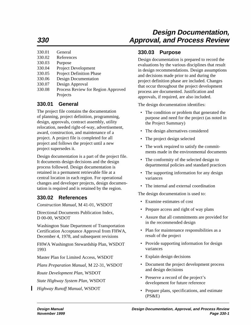
330.03 PurposeDesign documentation is prepared to record theevaluations by the various disciplines that resultin design recommendations. Design assumptionsand decisions made prior to and during theproject definition phase are included. Changesthat occur throughout the project developmentprocess are documented. Justification andapprovals, if required, are also included.
The design documentation identifies:
• The condition or problem that generated thepurpose and need for the project (as noted inthe Project Summary)
• The design alternatives considered
• The project design selected
• The work required to satisfy the commit-ments made in the environmental documents
• The conformity of the selected design todepartmental policies and standard practices
• The supporting information for any designvariances
• The internal and external coordination
The design documentation is used to:
• Examine estimates of cost
• Prepare access and right of way plans
• Assure that all commitments are provided forin the recommended design
• Plan for maintenance responsibilities as aresult of the project
• Provide supporting information for designvariances
• Explain design decisions
• Document the project development processand design decisions
• Preserve a record of the project’sdevelopment for future reference
• Prepare plans, specifications, and estimate(PS&E)
330.01 General330.02 References330.03 Purpose330.04 Project Development330.05 Project Definition Phase330.06 Design Documentation330.07 Design Approval330.08 Process Review for Region Approved
Projects
330.01 GeneralThe project file contains the documentationof planning, project definition, programming,design, approvals, contract assembly, utilityrelocation, needed right-of-way, advertisement,award, construction, and maintenance of aproject. A project file is completed for allproject and follows the project until a newproject supersedes it.
Design documentation is a part of the project file.It documents design decisions and the designprocess followed. Design documentation isretained in a permanent retrievable file at acentral location in each region. For operationalchanges and developer projects, design documen-tation is required and is retained by the region.
330.02 ReferencesConstruction Manual, M 41-01, WSDOT
Directional Documents Publication Index,D 00-00, WSDOT
Washington State Department of TransportationCertification Acceptance Approval from FHWA,December 4, 1978, and subsequent revisions
FHWA Washington Stewardship Plan, WSDOT1993
Master Plan for Limited Access, WSDOT
Plans Preparation Manual, M 22-31, WSDOT
Route Development Plan, WSDOT
State Highway System Plan, WSDOT
Highway Runoff Manual, WSDOT
Design Manual Design Documentation, Approval, and Process ReviewNovember 1999 Page 330-1

430 Modified Design Level
430.03 Roadway WidthsThe design of a project must not decrease theexisting roadway width.
Lane and shoulder widths are shown in Figures430-3 and 4. Consider joint use with other modesof transportation in shoulder design.
Review route continuity and roadway widths.Select widths on the tangents to be consistentthroughout a given section of the route. Make anychanges where the route characteristics change.
(1) Turning Roadway WidthsIt may be necessary to widen the roadway oncurves to accommodate large vehicles. The totaltwo-lane roadway width of a curve may not beless than that shown in Figure 430-5 or, if theinternal angle (delta) is less than 90 degrees,Figure 430-6. The proposed roadway width fora curve may not be less than that of the adjacenttangent sections.
The total roadway width from Figure 430-5 orFigure 430-6 may include the shoulder. Whenthe shoulder is included, full-depth pavementis required.
Widening of the total roadway width of a curveby less than 0.6 m is not required for existingtwo-lane roadways that are to remain in place.
(2) Median WidthSee Figure 430-3.
430.04 Ramp Lane WidthsRamp lane widths are shown in Figure 430-1 andin Figure 430-10. For ramps with radii less than100 m apply full design level see Chapter 640.
Curve Radius Lane Width
Tangent - 1200 m 3.9 m
900 m - 600 m 4.2 m
300 m - 100 m 4.5 m
Turning Ramp Lane WidthsModified Design Level
Figure 430-1
430.01 General430.02 Design Speed430.03 Roadway Widths430.04 Ramp Lane Widths430.05 Stopping Sight Distance430.06 Profile Grades430.07 Cross Slope430.08 Fill Slopes and Ditch Inslopes430.09 Intersections430.10 Structures
430.01 GeneralModified design level (M) preserves andimproves existing roadway geometrics, safety,and operational elements. This chapter providesthe design guidance that is unique to the modifieddesign level.
Design elements that do not have modified designlevel guidance include:
• Access control, see Chapter 1420• Access management, see Chapter 920• Basic safety, see Chapter 410• Clear zone, see Chapter 700• Traffic barriers, see Chapter 710• Gore area lighting, see Chapter 840• Interchange areas, see Chapter 940
Design elements that have both modified and fulldesign level components include:
• Horizontal alignment, see Chapter 620• Superelevation and shoulder cross slope,
see Chapter 640• Vertical alignment, see Chapter 630
430.02 Design SpeedWhen applying modified design level to aproject, select a design speed for use in the designprocess that reflects the character of the terrainand the type of highway. Select a speed that isnot less than the posted speed, the proposedposted speed, or the operating speed, whicheveris higher.
Design Manual Modified Design LevelNovember 1999 Page 430-1

430.05 Stopping Sight Distance(1) Existing Stopping Sight Distancefor Vertical CurvesFor crest vertical curves use the existing algebraicdifference in grades and the length of curve tocompare the existing condition to Figure 430-7.If corrective action is required by Figure 430-7,apply full design level and see Chapter 650.
When modified design level is being applied, sagvertical curves are not normally addressed.
(2) Stopping Sight Distance forHorizontal CurvesFor modified design level, use the existing lateralclearance to the sight obstruction and the curveradius to compare the existing condition toFigure 430-8. If corrective action is requiredby Figure 430-8, apply full design level and seeChapter 650.
For Figure 430-8, an obstruction is any objectwith a height of 0.6 m or more above the roadwaysurface on the inside of a curve. Examples ofpossible obstructions are median barrier, guard-rail, bridges, walls, cut slopes, wooded areas,and buildings.
430.06 Profile GradesWhen applying modified design level, profilegrades generally are not flattened. However,corrective action may be justified for combina-tions of steep grades and restricted horizontal orvertical curvature. Identify major modificationsto horizontal and vertical alignment in the ProjectDecisions Summary. Total removal of pavementand reconstruction of the subgrade are examplesof major modifications.
430.07 Cross SlopeOn all tangent sections, the normal cross slopesof the traveled way are 2 percent. Cross slopes upto 2 percent have a barely perceptible effect onvehicle steering, but cross slopes steeper than2 percent can be noticeable.
The algebraic difference in cross slopes is anoperational factor during a passing maneuveron a two-lane road. Its influence increases whenincreased traffic volumes decrease the numberand size of available passing opportunities.
If a longitudinal contiguous section of pavementis to be removed or is on a reconstructed align-ment, or if a top course is to be placed overexisting pavement, design the restored pavementto a cross slope of 2 percent.
A somewhat steeper cross slope may be neces-sary to facilitate pavement drainage in areas ofintense rainfall, even though this might be lessdesirable from the operational point of view.In such areas, the design cross slopes may beincreased to 2.5 percent with an algebraicdifference of 5 percent.
For existing pavements, cross slopes within arange of 1 to 3 percent may remain if there areno operational or drainage problems and— ona two-way, two-lane road — the followingconditions are met:
• The algebraic difference is not greater than4 percent where the ADT is greater than2000.
• The algebraic difference is not greater than5 percent where the ADT is 2000 or less.
• The algebraic difference is not greater than6 percent and the road is striped or signed forno passing.
If the existing pavement does not meet theconditions above, correct the cross slope(s) tobe within the range of 1.5 to 2.5 percent. For atwo-way, two-lane road, provide an algebraicdifference to meet the appropriate conditionsstated above except when facilitating drainagein areas of intense rainfall. When applyingmodified design level to a road with bituminoussurface treatment (BST), cross slope correctionis not required on the basis of algebraicdifferences alone.
Modified Design Level Design ManualPage 430-2 November 1999
To maintain or restore curb height, considerlowering the existing pavement level and correct-ing cross slope by grinding before an asphaltoverlay. On urban highways, the cross slope ofthe outside shoulder may be steepened to mini-mize curb height and other related impacts. Theshoulder may be up to 6 percent with a rolloverbetween the traveled way and the shoulder of nomore than 8 percent.
430.08 Fill Slopes and DitchInslopesForeslopes (fill slopes and ditch inslopes) and cutslopes are designed as shown in Figure 430-9 formodified design level main line roadway sec-tions. After the foreslope has been determined,use the guidance in Chapter 700 to determine theneed for a traffic barrier.
When a crossroad or road approach has steepforeslopes, there is the possibility that an errantvehicle might become airborne. Therefore, flattencrossroad and road approach foreslopes to 1:6where practical and at least to 1:4. Providesmooth transitions between the main lineforeslopes and the crossroad or road approachforeslopes. Where possible, move the crossroador road approach drainage away from the mainline. This can locate the pipe outside the designclear zone and reduce the length of pipe required.
430.09 Intersections(1) GeneralExcept as given below, design intersections tomeet the requirements in Chapter 910.
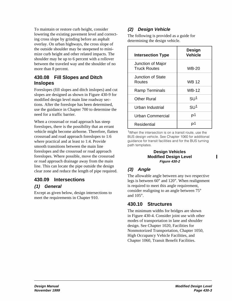
(2) Design VehicleThe following is provided as a guide fordetermining the design vehicle.
DesignIntersection Type Vehicle
Junction of MajorTruck Routes WB-20
Junction of StateRoutes WB 12
Ramp Terminals WB-12
Other Rural SU1
Urban Industrial SU1
Urban Commercial P1
Residential P1
1When the intersection is on a transit route, use theBUS design vehicle. See Chapter 1060 for additionalguidance for transit facilities and for the BUS turningpath templates.
Design VehiclesModified Design Level
Figure 430-2
(3) AngleThe allowable angle between any two respectivelegs is between 60° and 120°. When realignmentis required to meet this angle requirement,consider realigning to an angle between 75°and 105°.
430.10 StructuresThe minimum widths for bridges are shownin Figure 430-4. Consider joint use with othermodes of transportation in lane and shoulderdesign. See Chapter 1020, Facilities forNonmotorized Transportation, Chapter 1050,High Occupancy Vehicle Facilities, andChapter 1060, Transit Benefit Facilities.
Design Manual Modified Design LevelNovember 1999 Page 430-3

Geometric Design Data, Principal ArterialFigure 440-4b
Design M
anualF
ull Design Level
Novem
ber 1999P
age 440-9
Principal Arterial Notes:1 Justify the selection of a P-6 standard.2 The design year is 20 years after the year the construction is scheduled to begin.3 Where DHV exceeds 700, provide four lanes. For lower volumes, when the volume/capacity ratio is equal to or exceeds 0.75, consider the needs for a
future four-lane facility. When considering truck climbing lanes on a P-3 design class highway, perform an investigation to determine if a P-2 design classhighway is justified.
4 When considering a multilane highway, perform an investigation to determine if a truck climbing lane will satisfy the need.5 See Chapter 1420 for access control requirements.6 All main line and major-spur railroad tracks will be separated. Consider allowing at-grade crossings at minor-spur railroad tracks.7 Criteria for railroad grade separations are not clearly definable. Evaluate each site regarding the hazard potential. Provide justification for railroad grade
separations.8 The preferred design speed is within the range. Design speeds above the range may be selected, with justification. The lower end of the range is the
minimum design speed for the design class.9 3.6Êm lanes are required when the truck DHV is 6% or grater.10 Minimum left shoulder width is to be as follows: four lanes Ñ 1.2Êm: six or more lanes Ñ 3.0Êm. For 6-lane roadways, existing 1.8Êm left shoulders may
remain when no other widening is required.11 When curb section is used, a 1.8Êm shoulder outside the face of curb is acceptable. See Chapter 910 for shy distances at curbs.12 On freeways or expressways requiring less than eight lanes within the 20-year design period, provide sufficient median or lateral clearance and right of way to
permit addition of a lane in each direction if required by traffic increase after the 20-year period.13 When signing is required in the median of a six-lane section, the minimum width is 1.8Êm. If barrier is to be installed at a future date, a 2.4Êm minimum
median is required.14 Parking restricted when ADT is over 15,000.15 Submit Form 223-528, Pavement Type Determination.16 Provide right of way width 3 m desirable, 1.5 m minimum, wider than the slope stake for fill and slope treatment for cut. See Chapter 640 and the Standard
Plans for slope treatment information.17 19Êm from edge of traveled way.18 Make right of way widths not less than those required for necessary cross section elements.19 See Chapter 1120 for the minimum vertical clearance.20 For median widths 7.8Êm or less, address bridges in accordance with Chapter 1120.21 For pedestrian, bicycle, and sidewalk requirements see Chapter 1020. Curb requirements are in Chapter 910. Lateral clearances from the face of curb to
obstruction are in Chapter 700.22 Except in mountainous terrain, grades 1% steeper may be used in urban areas where development precludes the use of flatter grades or for one-way
downgrades.

Geometric Design Data, Minor ArterialFigure 440-5a
Full D
esign LevelD
esign Manual
Page 440-10
Novem
ber 1999
Divided Multilane Two-Lane Undivided Multilane
Design Class M-1 M-2 M-3 M-4 M-5(1)
Rural Urban Rural Urban Rural Urban Rural Urban Rural Urban
DHV in Design Year(2)
NHSNon NHS
Over 701 201-700(3)
401-70061-200
(4)
201-40060 and Under200 and Under
Over 701
Access Control(5) Partial Partial Partial or None None Special Cases
Separate Cross TrafficHighways
Railroads
Where Warranted
All
Where Warranted
All(6)
Where Warranted
Where Warranted(7)
Where Warranted
Where Warranted(7)
Where Warranted
Where Warranted (7)
Design Speed Range (mph)(8)
7050
7050
6040
7050
6040
6040
6030
7040
6030
Traffic LanesNumberWidth (m)
4 or 6 divided
3.6
2
3.6
2
3.6
2
3.6
4
3.6
4 or 6
3.3(9)
Shoulder Width (m)Right of Traffic
Left of Traffic
3.0
Variable(10)
2.4 1.8 1.2 2.4 2.4(11)
Median Width (m)4 lane6 lane
1818
4.86.6
1.2 0.6(12)
Parking Lanes Width (m) Ñ Minimum None None None 3.0 None 3.0 None 3.0(13)
Pavement Type(14) High As required High or Intermediate
Right of Way(15)
Ñ Min Width (m) (16) (17) 36 24 36 24 30 24 45 24
Structures (m)(18) Full Roadway Width
(19)12.0 10.8 9.6 Full Roadway Width
Other Design Considerations-Urban (20) (20) (20) (20)
Grades (%)(21)
Rural Ñ Design Speed (mph) Urban Ñ Design Speed (mph)
Type of Terrain 40 50 60 70 80 30 40 50 60
Level 5 4 3 3 3 8 7 6 5
Rolling 6 5 4 4 4 9 8 7 6
Mountainous 8 7 6 5 5 11 10 9 8

Design Manual Investigation of Soils, Rock, and Surfacing MaterialsNovember 1999 Page 510-1
Investigation of Soils,510 Rock, and Surfacing Materials
inform the RME and OSC Geotechnical Branchas soon as possible so that the geotechnicaldesign can be adapted to the changes withoutsignificant delay to the project.
510.02 ReferencesConstruction Manual, M 41-01, WSDOT
Hydraulics Manual, M 23-03, WSDOT
Plans Preparation Manual, M 22-31, WSDOT
Standard Plans for Road, Bridge, and MunicipalConstruction (Standard Plans), M 21-01,WSDOT
Standard Specifications for Road, Bridge,and Municipal Construction (StandardSpecifications), M 41-10, WSDOT
WSDOT Pavement Guide for Design, Evaluationand Rehabilitation
510.03 Materials Sources(1) GeneralThe region’s Project Development Engineer(RPDE) determines when a materials source isneeded. The region’s Materials Engineer (RME)determines the best materials source for theproject. (See Figure 510-1.) It is preferred thatexisting approved materials source sites be usedwhen there are suitable sites available. Whenthere are no approved sites available, the RMEconducts a site investigation. The OlympiaService Center (OSC) Geotechnical Branchprovides assistance upon request.
The RME selects sources for gravel base,borrow excavation and gravel borrow, crushedsurfacing materials, mineral and concreteaggregates, riprap, and filler only after carefulinvestigation of:
• The site. (Consider the adequacy of thework area.)
• The quality of the material.
510.01 General510.02 References510.03 Materials Sources510.04 Geotechnical Investigation, Design,
and Reporting510.05 Use of Geotechnical Consultants510.06 Geotechnical Work by Others510.07 Surfacing Report510.08 Documentation
510.01 GeneralIt is the responsibility of the Washington StateDepartment of Transportation (WSDOT) tounderstand the characteristics of the soil androck materials that support or are adjacent to thetransportation facility to ensure that the facility,when designed, will be adequate to safely carrythe estimated traffic. It is also the responsibilityof WSDOT to ensure the quality and quantity ofall borrow materials used in the construction oftransportation facilities.
The following information serves as guidancein the above areas. Where a project consists of asurface overlay of an existing highway, require-ments as set forth in WSDOT Pavement Guide forDesign, Evaluation and Rehabilitation are used.
To identify the extent and estimated cost fora project, it is necessary to obtain and use anadequate base data. In recognition of this need,preliminary soils investigation work beginsduring project definition. This allows earlyinvestigative work and provides necessary datain a timely manner for use in project definitionand design. More detailed subsurface investiga-tion follows during the project design and plan,specification, and estimate (PS&E) phases.
It is essential to get the region’s MaterialsEngineer (RME) and the Olympia Service Center(OSC) Geotechnical Branch involved in theproject design as soon as possible once the needfor geotechnical work is identified. See 510.04(3)for time-estimate information. Furthermore, ifmajor changes occur as the project is developed,

Investigation of Soils, Rock, and Surfacing Materials Design ManualPage 510-2 November 1999
• The quantity of the material. (Consider theneeds of the immediate project and theneeds to support future maintenance andconstruction work in the area.)
• Reclamation requirements.
• Aesthetic considerations.
• Economic factors.
• Ability to preserve or enhance thevisual quality of the highway and localsurroundings.
Once the materials source investigation andlaboratory testing have been completed the RMEprepares a materials source report. The materialssource report summarizes the site geology, siteinvestigation (including boring and test pit logs),source description, quality and quantity ofmaterial available, and other aspects of thematerials sources that are relevant.
(2) Materials Source ApprovalThe RME submits the materials source reportto the OSC Geotechnical Branch for reviewand approval.
The OSC Materials Office and the OSC DesignOffice must approve each pit or quarry site beforeit is purchased, leased, or acquired on a royaltybasis. Until the approval process is complete, theproject cannot be advertised for bids. Local andstate permits are required for materials sources.To avoid delay in advertising the project, beginthe site investigations and permitting process inthe early stages of project definition.
510.04 Geotechnical Investigation,Design, and Reporting(1) GeneralA geotechnical investigation is conducted onall projects that involve significant gradingquantities, unstable ground, or foundations forstructures in a manner that preserves the safetyof the public who use the facility, as well aspreserving the economic investment by the stateof Washington. Geotechnical engineering mustbe conducted by engineers or engineering geolo-gists who possess adequate geotechnical training
and experience, and must be conducted in accor-dance with regionally or nationally acceptedgeotechnical practice. Where required by law,geotechnical engineering must be performedby, or under the direct supervision of, a personlicensed to perform such work in the state ofWashington.
(2) Key Contacts for InitiatingGeotechnical WorkIn general, the RME functions as the clearinghouse for all geotechnical work, with the excep-tion of structural projects and Washington StateFerries (WSF) projects. The RME takes the leadin conducting the geotechnical work if thegeotechnical work required is such that theground is stable and relatively firm, bedrock isnot involved, and the design of the projectgeotechnical elements does not require special-ized geotechnical design expertise. If this is notthe case, the RME asks for the involvement andservices of the OSC Geotechnical Branch. Theyrespond to and provide recommendations directlyto the region’s project design office (or the OSCEquipment and Facilities Office in the case ofFacilities projects), but always keeping the RME“in the loop.”
For structural projects (bridges and tunnels, forexample), the Bridge and Structures Office worksdirectly with the OSC Geotechnical Branch.
For WSF projects, the Terminal EngineeringOffice works directly with the RME or the OSCGeotechnical Branch, depending on the nature ofthe project.
For walls and noise walls, see Chapters 1130 and1140, respectively. For geosynthetic design, seeChapter 530.
(3) Scheduling Considerations forGeotechnical WorkThe region’s Design Office, Bridge andStructures Office, WSF, and the Equipment andFacilities Office are responsible for identifyingthe potential need for geotechnical work, andrequesting time and budget estimates from theRME or the OSC Geotechnical Branch, as earlyas practical to prevent delays to the project.

Design Manual Investigation of Soils, Rock, and Surfacing MaterialsNovember 1999 Page 510-3
Once the geotechnical design request and thesite data are received by the RME or the OSCGeotechnical Branch, it can take anywhere fromtwo to six months, or more, to complete thegeotechnical design, depending on the complex-ity of the project, whether or not test holes areneeded, current workload, the need to give thework to consultants, and how long it takes toobtain environmental permits and rights ofentry (ROE).
If a consultant must be used, the minimum timerequired to complete a design (for even a simpleproject) is typically 2.5 months.
In true emergency situations (a highway blockedby a landslide or a collapsed bridge, forexample), it is possible to get geotechnical designwork completed (in house or by consultants)more rapidly to at least provide a design fortemporary mitigation.
Consider all of these factors when deciding howsoon to initiate the geotechnical work for aproject but, in general, the sooner, the better.
(4) Site Data and Permits Needed toInitiate Geotechnical WorkTo initiate geotechnical work on a projectduring the design and PS&E phases, provide thefollowing information:
(a) Project description.
(b) Plan sheets showing the following:
• Station and location of cuts, fills, walls,bridges, retention/detention ponds, or othergeotechnical features to be designed.
• Existing utilities (as-built plans areacceptable).
• Right of way limits.
• Wetlands.
• Drainage features.
• Existing structures.
• Other features or constraints that could affectthe geotechnical design or investigation.
(c) Electronic files, or cross sections every 15to 20 m or as appropriate, to define existing and
new ground line above and below the wall, cut,fill, and other pertinent information.
• Show stationing.
• Show locations of existing utilities, right ofway lines, wetlands, and other constraints.
• Show locations of existing structures thatmight contribute load to the cut or fill.
(d) Right of entry agreements and permitsrequired for geotechnical investigation.
(e) Due date and work order number.
(f) Contact person.
When the alignment and any constraints as notedabove are staked, the stationing on the plans andin the field must be in the same units. Physicalsurveys are preferred to photogrammetric surveysto ensure adequate accuracy of the site data.
Permits and agreements to be supplied by theregion might include:
• HPA
• Shoreline permits
• Tribal lands and waters
• Railroad easement and right of way
• City, county or local agency use permits
• Sensitive area ordinance permits
The region’s project office is also responsible forproviding the stations, offsets, and elevations oftest holes to the nearest 0.3 m once the test holeshave been drilled. Provide test hole locationsusing state plane coordinates as well, if available.
(5) Overview of GeotechnicalDesign Objectives for the VariousProject Stages(a) Project Definition. The project designoffice uses the geotechnical investigation resultsobtained during the project definition phase todevelop the project delivery cost and schedule.Geotechnical recommendations provided for thisphase will be at the conceptual/feasibility level.The investigation for this phase usually consistsof a visual project walk-through and a review ofthe existing records, geologic maps, and so forth.

Investigation of Soils, Rock, and Surfacing Materials Design ManualPage 510-4 November 1999
For projects of significant geotechnical scope andcomplexity, and if soil borings are not availableat critical locations within the project, some soilborings might be drilled at this time. Potentialgeotechnical hazards (earthquake faults, liquefac-tion, landslides, rockfall, soft ground, forexample) are identified during project definition,and conceptual hazard avoidance or mitigationplans are developed. Future geotechnical designservices needed in terms of time and cost, includ-ing the need for special permits to perform thegeotechnical exploration (critical areas ordi-nances), are determined at this time.
(b) Project Design. Once the roadway geom-etry is established, detailed design of cut and fillslopes, adequate to establish the right-of-wayneeds, is accomplished. Once approximate walllocations and heights are known, preliminarydesign of walls is performed to establish feasibil-ity, primarily to establish right-of-way needs (asis true for slopes) and likely wall types. A similarlevel of design is applied to hydraulic structures,and to determine overall construction staging andconstructibility requirements to address thegeotechnical issues at the site. Conceptual and/ormore detailed preliminary bridge foundationdesign is conducted during this phase if it was notconducted during project definition. Before theend of this phase, the geotechnical data necessaryto allow future completion of the PS&E leveldesign work is gathered (final geometric data, testhole data, and so forth.).
(c) PS&E Development. Final design of allgeotechnical project features is accomplished.Recommendations for these designs, as well asspecial provisions and plan details to incorporatethe geotechnical design recommendations in thePS&E, are provided in the geotechnical report.Minor geotechnical features such as signal/signfoundations and small detention/retention pondsare likely to be addressed at this stage, as theproject details become clearer. Detailed recom-mendations for the constructibility of the projectgeotechnical features are also provided.
(6) Earthwork(a) Project Definition. The project designercontacts and meets with the RME, and the OSCGeotechnical Branch as needed, at the project site
to conduct a field review to help identify thegeotechnical issues for the project.
In general, if soil/rock conditions are poor and/orlarge cuts or fills are anticipated, the RMErequests that the OSC Geotechnical Branchparticipate in the field review and reportingefforts.
The designer provides a description and locationof the proposed earthwork to the RME.
• For widening of existing facilities, theanticipated width, length, and location ofthe widening, relative to the current facility,are provided.
• For realignments, the approximate newlocation proposed for the facility is provided.
• Locations in terms of length can be by milepost or stations.
A brief conceptual level report is provided to thedesigner that summarizes the results of theinvestigation.
(b) Project Design. Geotechnical datanecessary to allow completion of the PS&E leveldesign is compiled during the design phase. Thisincludes soils borings, testing, and final geomet-ric data. Detailed design of cut and fill slopes canbe done once the roadway geometry is estab-lished and geotechnical data is available. Thepurpose of this design effort is to determine themaximum stable cut or fill slope and, for fills,potential for short and long term settlement. Also,the usability of the cut materials and the type ofborrow needed for the project, if any, is evalu-ated. Evaluate the use of soil bioengineering as anoption for building steeper slopes or to preventsurface erosion. See the Chapter 1350 - SoilBioengineering for more information.
The designer requests a geotechnical report fromthe RME. The site data indicated in 510.04(4), asapplicable, is provided. It is important that therequest for the geotechnical report be made asearly in the design phase as practical. Cost andschedule requirements to generate the report areproject specific and can vary widely. The timerequired to obtain permits and rights of entry

Design Manual Investigation of Soils, Rock, and Surfacing MaterialsNovember 1999 Page 510-5
must be considered when establishing schedulerequirements.
The RME, in conjunction with the OSCGeotechnical Branch, provides the followinginformation as part of the geotechnical report (asapplicable):
1. General description of the regional and sitegeology
2. Summary of the investigation
3. Boring logs
4. Laboratory tests and results
5. Soil/rock unit descriptions
6. Ground water conditions
7. Embankment design recommendations
• The slope required for stability
• Estimated amount and rate of settlement
• Stability and settlement mitigation require-ments
• Construction staging requirements
• Effects of site constraints
• Monitoring needs
• Material and compaction requirements
• Subgrade preparation
8. Cut design recommendations
• The slope required for stability
• Stability mitigation requirements (deepseated stability and erosion)
• Identification of seepage areas and how tomitigate them
• Effects of site constraints
• Monitoring requirements
• Usability of excavated cut material, includinggradation, moisture conditions and need foraeration, and shrink/swell characteristics
The recommendations include the backgroundregarding analysis approach and any agreements
with the region or other customers regarding thedefinition of acceptable level of risk.
The project office uses the report to finalizedesign decisions for the project. To meet slopestability requirements, additional right of waymight be required or a wall might be needed.Wall design is covered in Chapter 1130. Con-struction timing might require importing materialrather than using cut materials. The report is usedto address this and other constructibility issues.The report is also used to proceed with comple-tion of the project PS&E design.
(c) PS&E Development. Adequategeotechnical design information to completethe PS&E is typically received during projectdesign. Additional geotechnical work might beneeded when right of way cannot be acquired,restrictions are included in permits, or otherrequirements are added that result in changesin the design.
Special provisions and plan details, if notreceived as part of the report provided duringproject design, are developed with the assistanceof the RME or the OSC Geotechnical Branch.The project designer uses this information, aswell as the design phase report, to complete thePS&E documents. Both the region’s MaterialsSection and the OSC Geotechnical Branch canreview the contract plans before the PS&E reviewprocess begins, if requested. Otherwise, they willreview the contract plans during the normalPS&E review process.
(7) Hydraulic Structures andEnvironmental Mitigation(a) Project Definition. The designer providesa description and location of the proposedhydraulic/environmental improvements and otherpertinent site information, and discusses theextent of the hydraulics and environmentalimprovements, with both the RME and theHydraulics Sections, to identify the geotechnicalissues to be investigated. At this stage, only theidentification and feasibility of the proposedhydraulic structures or environmental mitigationare investigated. The cost and schedule require-
Investigation of Soils, Rock, and Surfacing Materials Design ManualPage 510-6 November 1999
ments for the geotechnical investigation are alsodetermined at this time.
Examples of hydraulic structures include, but arenot limited to, large culverts, pipe arches, under-ground detention vaults, and fish passagestructures. Examples of environmental mitigationinclude, but are not limited to, detention/retentionponds and wetland creation.
(b) Project Design. The designer requests ageotechnical report from the RME. The site dataindicated in 510.04(4), as applicable, is providedalong with the following information:
• Pertinent field observations (such as unstableslopes, existing soft soils or boulders, orerosion around and damage to existingculverts or other drainage structures).
• Jurisdictional requirements for geotechnicaldesign of berms/dams.
It is important that the request for thegeotechnical report be made as early in the designphase as practical. Cost and schedule require-ments to generate the report are project specificand can vary widely. The time required to obtainpermits and rights of entry must be consideredwhen establishing schedule requirements.
The RME, with support from the OSCGeotechnical Branch as needed, provides thefollowing information, when requested and whereapplicable, as part of the project geotechnicalreport:
• Soil boring logs.
• Soil pH and resistivity.
• Water table elevation.
• Soil infiltration rates (highest rate forassessing spill containment/aquifer protectionand long-term rate for determining pondcapacity).
• Bearing capacity and settlement for hydraulicstructure foundations.
• Slope stability for ponds.
• Retention berm/dam design.
• Potential for and amount of differentialsettlement along culverts and pipe arches
and the estimated time required for settlementto occur.
• Soil pressures and properties (primarily forunderground detention vaults).
• Erosion potential.
• Geosynthetic design per Chapter 530.
• Recommendations for mitigation of the effectof soft or unstable soil on the hydraulicstructures.
• Recommendations for construction.
Note that retaining walls that are part of a pond,fish passage, and the like, are designed perChapter 1130.
The project designer uses the geotechnicalinformation to:
• Finalize design decisions.
• Evaluate and mitigate environmental issues.
• Proceed with completion of the PS&E design(includes determining the most cost effectivehydraulic structure/pond to meet the desiredobjectives, locating and sizing ponds andfoundations for hydraulic structures, struc-tural design, mitigating the effects ofsettlement, satisfying local jurisdictionalrequirements for design, and so forth).
(c) PS&E Development. During PS&Edevelopment, the designer uses the informationprovided in the geotechnical report as follows:
• Select pipe materials in accordance withcorrosion, resistivity, and abrasionguidelines in the Hydraulics Manual.
• Consider and include constructionrecommendations.
Additional design and specification guidanceand support from the RME or the OSCGeotechnical Branch are sought as needed. Bothsections provide careful review of the contractplans before the PS&E review process begins,if requested. Otherwise, they will review thecontract plans during the normal PS&E reviewprocess.
Design Manual Investigation of Soils, Rock, and Surfacing MaterialsNovember 1999 Page 510-7
(8) Signals, Sign Bridges, CantileverSigns, and Luminaire Foundations(a) Project Definition and Design.Geotechnical information is usually not requiredfor signals, sign bridges, cantilever signs, andluminaires during project definition.
The region’s Traffic Office contacts the RMEfor conceptual foundation recommendations.The conceptual recommendations are based onexisting information in the area, and identifyif Standard Plan foundations are feasible or ifspecial design foundations are required. If goodsoils are anticipated or the foundations will beplaced in fill, Standard Plan foundations canbe assumed. If special design foundations arerequired, additional time and money can beincluded in the project to accommodate increasedfield exploration for foundation design, OSCGeotechnical Branch involvement, and structuraldesign by the Bridge and Structures Office.
(b) PS&E Development. Foundation recom-mendations are made by either the RME or theOSC Geotechnical Branch. The recommendationsprovide all necessary geotechnical information tocomplete the PS&E.
The region’s Traffic Office (or region’s ProjectEngineer in some cases) is responsible fordelivering the following project information tothe region’s Materials Engineer:
• Plan sheet showing the location of thestructures (station and offset) and the plannedstructure type.
• Applicable values for: XYZ, strain pole class,sign bridge span length, luminaire height,variable message sign weight, wind load,CCTV pole height, and known utilityinformation in the area.
The RME provides the following information tothe requester if Standard Plan foundation typescan be used:
• Allowable lateral bearing capacity of the soil.
• Results of all field explorations.
• Groundwater elevation.
• Foundation constructibility.
The region uses this information to complete theplan sheets and prepare any special provisions. Ifutilities are identified during the field investiga-tion that could conflict with the foundations, theregion’s project office pursues moving or accom-modating the utility. Accommodation couldrequire special foundation designs.
If special designs are required, the RME notifiesthe requester that special designs are required andforwards the information received from theregion to the Geotechnical Branch. TheGeotechnical Branch provides the Bridge andStructures Office with the necessary geotechnicalrecommendations to complete the foundationdesigns. The region coordinates with the Bridgeand Structures Office to ensure that they have allthe information necessary to complete the design.Depending on the structure type and complexity,the Bridge and Structures Office might producethe plan sheets and special provisions for thefoundations, or they might provide the regionwith information so that the region can completethe plan sheets and special provisions.
(9) Buildings, Park and Ride Lots,Rest Areas, and CommunicationTowersIn general, the RME functions as the clearinghouse for the geotechnical work to be conductedin each of the phases for technical review of thework if the work is performed by consultants, orfor getting the work done in-house. For sites anddesigns that are more geotechnically complex,the RME contacts the OSC Geotechnical Branchfor assistance.
Detailed geotechnical investigation guidance isprovided in Facilities Operating Procedure 9-18,“Site Development.” In summary, this guidanceaddresses the following phases of design:
(a) Site Selection. Conceptual geotechnicalinvestigation (based on historical data andminimal subsurface investigation) of severalalternative sites is performed in which thegeotechnical feasibility of each site for theintended use is evaluated, allowing the sites to beranked. In this phase, geological hazards (land-slides, rockfall, compressible soils, liquefaction,

Investigation of Soils, Rock, and Surfacing Materials Design ManualPage 510-8 November 1999
and so forth) are identified, and geotechnical dataadequate to determine a preliminary cost todevelop and build on the site is gathered.
(b) Schematic Design. For the selected site, thebest locations for structures, utilities, and otherelements of the project are determined based onsite constraints and ground conditions. In thisphase, the site is characterized more thoroughlythan in the site selection phase, but subsurfaceexploration is not structure specific.
(c) Design Development. The final locations ofeach of the project structures, utilities, and otherproject elements determined from the schematicdesign phase are identified. Once these finallocations are available, a geotechnical investiga-tion adequate to complete the final design of eachof the project elements (structure foundations,detention/retention facilities, utilities, parkinglots, roadways, site grading, and so forth) isconducted. From this investigation and design,the final PS&E is developed.
(10) Retaining Walls, ReinforcedSlopes, and Noise Walls(a) Project Definition. The designer provides adescription and location of the proposed walls orreinforced slopes, including the potential size ofthe proposed structures and other pertinent siteinformation, to the RME. At this stage, only theidentification and feasibility of the proposedwalls or reinforced slopes are investigated. Afield review may also be conducted at this time aspart of the investigation effort. In general, ifsoil/rock conditions are poor and/or large wallsor reinforced slopes are anticipated, the RMErequests that the OSC Geotechnical Branchparticipate in the field review and reportingefforts. The cost and schedule requirements forthe geotechnical investigation are also determinedat this time.
A brief conceptual level report that summarizesthe results of the investigation may be providedto the designer at this time, depending on thecomplexity of the geotechnical issues.
(b) Project Design and PS&E Development.Geotechnical data necessary to allow completionof the PS&E level design for walls and reinforced
slopes are compiled during the design and PS&Edevelopment phases. This includes soils borings,testing, and final geometric data. Detailed designof walls and reinforced slopes can be done oncethe roadway geometry is established andgeotechnical data are available. The purpose ofthis design effort is to determine the wall andslope geometry needed for stability, noise walland retaining wall foundation requirements, andthe potential for short- and long-term settlement.
The designer requests a geotechnical report fromthe RME for retaining walls, noise walls, andreinforced slopes that are not part of the bridgepreliminary plan. For walls that are part of thebridge preliminary plan, the Bridge andStructures Office requests the geotechnical reportfor the walls from the OSC Geotechnical Branch.For both cases, see Chapter 1130 for the detaileddesign process for retaining walls and reinforcedslopes and Chapter 1140 for the detailed designprocess for noise walls. It is important thatrequests for a geotechnical report be made asearly in the design phase as practical. The timerequired to obtain permits and rights of entrymust be considered when establishing schedulerequirements.
For retaining walls and reinforced slopes, the sitedata to be provided with the request for ageotechnical report are as indicated inChapter 1130. Also supply right of entry agree-ments and permits required for the geotechnicalinvestiagion. The site data indicated in 510.04(4),as applicable, are provided for noise walls.
The RME or the OSC Geotechnical Branch (seeChapter 1130 or 1140 for specific responsibilitiesfor design), provides the following information aspart of the geotechnical report (as applicable):
1. General description of the regional and sitegeology
2. Summary of the investigation
3. Boring logs
4. Laboratory tests and results
5. Soil/rock unit descriptions
6. Ground water conditions

Design Manual Investigation of Soils, Rock, and Surfacing MaterialsNovember 1999 Page 510-9
7. Retaining wall/reinforced slope and noisewall recommendations
• Recommended geometry for stability
• Stability and settlement mitigation require-ments, if needed
• Foundation type and capacity
• Estimated amount and rate of settlement
• Design soil parameters
• Construction staging requirements
• Effects of site constraints
• Monitoring needs
• Material and compaction requirements
• Subgrade preparation
The recommendations may also include thebackground regarding analysis approach and anyagreements with the region or other customersregarding the definition of acceptable level ofrisk. Additional details and design issues to beconsidered in the geotechnical report are asprovided in Chapter 1130 for retaining walls andreinforced slopes and in Chapter 1140 for noisewalls. The project designer uses this informationfor final wall/reinforced slope selection and tocomplete the PS&E.
For final PS&E preparation, special provisionsand plan details (if not received as part of thereport provided during project design) are devel-oped with the assistance of the region MaterialsSection or the OSC Geotechnical Branch. Boththe region Materials Section and the OSCGeotechnical Branch can review the contractplans before the PS&E review process begins, ifrequested. Otherwise, they will review thecontract plans during the normal PS&E reviewprocess.
(11) Unstable SlopesUnstable slope mitigation includes the stabiliza-tion of known landslides and rockfall that occuron slopes adjacent to the WSDOT transportationsystem, and that have been programmed underthe P3 unstable slope program.
(a) Project Definition. The region’s projectoffice provides a description and location of theproposed unstable slope mitigation work to theRME. Location of the proposed work can be milepost limits or stationing. The region’s projectdesigner meets at the project site with the RMEand the OSC Geotechnical Branch to conduct afield review, discuss project requirements, and toidentify geotechnical issues associated with theunstable slope project. The RME requests that theOSC Geotechnical Branch participate in the fieldreview and project definition reporting.
The level of work in the project definition phasefor unstable slopes is conceptual in nature, notfinal design. The geotechnical investigationgenerally consists of a field review, a moredetailed assessment of the unstable slope, reviewof the conceptual mitigation developed during theprogramming phase of the project, and proposedmodification (if any) to the original conceptuallevel unstable slope mitigation. The design phasegeotechnical services cost and schedule, includ-ing any required permits, are determined at thistime. A brief conceptual level report is providedto the project designer that summarizes the resultsof the project definition investigation.
(b) Project Design. Geotechnical informationand field data necessary to complete the unstableslope mitigation design is compiled during thisdesign phase. This work includes, depending onthe nature of the unstable slope problem, testborings, rock structure mapping, geotechnicalfield instrumentation, laboratory testing, andslope stability analysis. The purpose of thisdesign effort is to determine the most appropriatemethod (s) to stabilize the known unstable slope.
The designer requests a geotechnical report fromthe OSC Geotechnical Branch through the RME.The site data indicated in 510.04(4), as appli-cable, is provided along with the followinginformation:
• Plan sheet showing the station and location ofthe proposed unstable slope mitigationproject.
• If requested, Digital Terrain Model (DTM)files necessary to define the on-ground
Investigation of Soils, Rock, and Surfacing Materials Design ManualPage 510-10 November 1999
topography of the project site. The limits ofthe DTM will have been defined during theproject definition phase.
It is important that the request for thegeotechnical report be made as early in the designphase as practical. Cost and schedule require-ments to generate the report are project specificand can vary widely. Unstable slope designinvestigations might require geotechnical moni-toring of ground movement and ground waterover an extended period of time to develop therequired field information for the unstable slopemitigation design. The time required to obtainrights of entry and other permits, as well as thelong-term monitoring data, must be consideredwhen establishing schedule requirements for thegeotechnical report.
The OSC Geotechnical Branch provides thefollowing information as part of the projectgeotechnical report (as applicable):
• General site description and summary of sitegeology.
• Summary of the field investigation.
• Boring logs.
• Laboratory tests and results.
• Geotechnical field instrumentation results.
• Summary of the engineering geology of thesite including geologic units encountered.
• Unstable slope design analysis and mitigationrecommendations.
• Constructibility issues associated with theunstable slope mitigation.
• Appropriate special provisions for inclusionin the contact plans.
The region’s project design office uses thegeotechnical report to finalize the design deci-sions for the project and the completion of thePS&E design.
(c) PS&E Development. Adequategeotechnical design information to complete thePS&E is typically obtained during the projectdesign phase. Additional geotechnical work
might be needed when right of way cannot beacquired, restrictions are included in permits,or other requirements are added that result inchanges to the design.
Special provisions, special project elements,and design details (if not received as part of thedesign phase geotechnical report) are developedwith the assistance of the RME and the OSCGeotechnical Branch. The region’s projectdesigner uses this information in conjunctionwith the design phase geotechnical report tocomplete the PS&E document. The RME and theOSC Geotechnical Branch can review the con-tract plans before the PS&E review begins, ifrequested. Otherwise, they will review thecontract plans during the normal PS&E reviewprocess.
(12) Rockslope Design(a) Project Definition. The region’s projectoffice provides a description and location of theproposed rock excavation work to the RME. Forwidening of existing rock cuts, the anticipatedwidth and length of the proposed cut in relation-ship to the existing cut are provided. For newalignments, the approximate location and depthof the cut are provided. Location of the proposedcut(s) can be mile post limits or stationing. Theproject designer meets at the project site withthe RME and the OSC Geotechnical Branch toconduct a field review, discusses project require-ments, and identify any geotechnical issuesassociated with the proposed rock cuts. The RMErequests that the OSC Geotechnical Branchparticipate in the field review and projectdefinition reporting.
The level of rock slope design work for theproject definition phase is conceptual in nature.The geotechnical investigation generally consistsof the field review, review of existing records, anassessment of existing rockslope stability, andpreliminary geologic structure mapping. Thefocus of this investigation is to assess the feasibil-ity of the rock cuts for the proposed widening orrealignment, not final design. A brief conceptuallevel report that summarizes the result of the

Design Manual Investigation of Soils, Rock, and Surfacing MaterialsNovember 1999 Page 510-11
project definition investigation is provided to theproject designer.
(b) Project Design. Detailed rockslope designis done once the roadway geometrics have beenestablished. The rockslope design cannot befinalized until the roadway geometrics have beenfinalized. Geotechnical information and field datanecessary to complete the rockslope design arecompiled during this design phase. This workincludes rock structure mapping, test borings,laboratory testing, and slope stability analysis.The purpose of this design effort is to determinethe maximum stable cut slope angle, and anyadditional rockslope stabilization measures thatcould be required.
The designer requests a geotechnical report fromthe OSC Geotechnical Branch through the RME.The site data indicated in 510.04(4), as appli-cable, is provided.
It is important that the request for thegeotechnical report be made as early in the designphase as practical. Cost and schedule require-ments to generate the report are project specificand can vary widely. The time required to obtainpermits and rights of entry must be consideredwhen establishing schedule requirements.
The OSC Geotechnical Branch provides thefollowing information as part of the projectgeotechnical report (as applicable):
1. General site description and summary of sitegeology.
2. Summary of the field investigation.
3. Boring logs.
4. Laboratory tests and results.
5. Rock units encountered within the projectlimits.
6. Rock slope design analysis and recommenda-tions.
• Type of rockslope design analysis conductedand limitation of the analysis. Also includedwill be any agreements with the region andother customers regarding the definition ofacceptable risk
• The slope(s) required for stability
• Additional slope stabilization requirements(rock bolts, rock dowels, and so forth.)
• Rockslope ditch criteria (See Chapter 640)
• Assessment of rippability
• Blasting requirements including limitationson peak ground vibrations and air blast over-pressure, if required
• Usability of the excavated material includingestimates of shrink and swell
• Constructibility issues associated with therock excavation
The project office uses the geotechnical report tofinalize the design decisions for the project, andthe completion of the PS&E design for therockslope elements of the project.
(c) PS&E Development. Adequategeotechnical design information to complete thePS&E is typically obtained during the projectdesign phase. Additional geotechnical workmight be needed when right of way cannot beacquired, restrictions are included in permits, orother requirements are added that result in changeto the design.
Special provisions, special blasting requirements,and plans details, if not received as part of thedesign phase geotechnical report, are developedwith the assistance of the RME or the OSCGeotechnical Branch. The project designer usesthis information in conjunction with the designphase geotechnical report to complete the PS&Edocuments. The RME and the OSC GeotechnicalBranch review the contract plans before thePS&E review begins, if requested. Otherwise,they will review the contract plans during thenormal PS&E review process.
(13) Bridge Foundations(a) Project Definition. The OSC GeotechnicalBranch supports the project definition process todevelop reasonably accurate estimates of bridgesubstructure costs. For major projects and forprojects that are located in areas with little or noexisting geotechnical information, a field review

Investigation of Soils, Rock, and Surfacing Materials Design ManualPage 510-12 November 1999
is recommended. The region’s office responsiblefor project definition coordinates field reviews.Subsurface exploration (drilling) is usually notrequired at this time, but might be needed if costestimates cannot be prepared within an accept-able range of certainty.
The Bridge and Structures Office, once they havereceived the necessary site data from the region’sproject office, is responsible for delivering thefollowing project information to the OSCGeotechnical Branch:
• Alternative alignments and/or locations ofbridge structures.
• A preliminary estimate of channelization(structure width).
• Known environmental constraints.
The Bridge and Structures and region offices canexpect to receive the following from the OSCGeotechnical Branch:
• Summary or copies of existing geotechnicalinformation.
• Identification of geotechnical hazards (slides,liquefiable soils, soft soil deposits, and soforth.).
• Identification of permits that might berequired for subsurface exploration (drilling).
• Conceptual foundation types and depths.
• If requested, an estimated cost and time tocomplete a geotechnical foundation report.
The Bridge Office uses this information to refinepreliminary bridge costs. The region’s projectoffice uses the estimated cost and time to com-plete a geotechnical foundation report to developthe project delivery cost and schedule.
(b) Project Design. The OSC GeotechnicalBranch assists the Bridge and Structures Officewith preparation of the bridge Preliminary Plan.Geotechnical information gathered for projectdefinition will normally be adequate for thisphase, as test holes for the final bridge designcannot be drilled until accurate pier locationinformation is available. For selected majorprojects, a type, size, and location (TS&L)
report might be prepared which usually requiressome subsurface exploration to provide a moredetailed, though not final, estimate of foundationrequirements.
The Bridge Office is responsible for deliveringthe following project information, based onbridge site data received from the region’s projectoffice, to the OSC Geotechnical Branch:
• Anticipated pier locations
• Approach fill heights
• For TS&L, alternate locations/alignments/structure types
The Bridge Office can expect to receive:
• Conceptual foundation types, depths andcapacities
• Permissible slopes for bridge approaches
• For TS&L, a summary of site geology andsubsurface conditions, and more detailedpreliminary foundation design parametersand needs
• If applicable or requested, erosion or scourpotential
The Bridge Office uses this information tocomplete the bridge preliminary plan. Theregion’s project office confirms right of wayneeds for approach embankments. For TS&L,the geotechnical information provided is used forcost estimating and preferred alternate selection.The preliminary plans are used by the OSCGeotechnical Branch to develop the sitesubsurface exploration plan.
(c) PS&E Development. During this phase,or as soon as a 95 percent preliminary plan isavailable, subsurface exploration (drilling) isperformed and a geotechnical foundation reportis prepared to provide all necessary geotechnicalrecommendations needed to complete the bridgePS&E.
The Bridge Office is responsible for deliveringthe following project information to the OSCGeotechnical Branch:

Design Manual Investigation of Soils, Rock, and Surfacing MaterialsNovember 1999 Page 510-13
• 95 percent preliminary plans (concurrent withdistribution for region approval)
• Estimated foundation loads and allowablesettlement criteria for the structure, whenrequested
The Bridge Office can expect to receive:
• Bridge geotechnical foundation report
The Bridge and Structures Office uses thisinformation to complete the bridge PS&E. Theregion’s project office reviews the geotechnicalfoundation report for construction considerationsand recommendations that might affect regionitems, estimates, staging, construction schedule,or other items.
Upon receipt of the structure PS&E review set,the OSC Geotechnical Branch provides theBridge and Structures Office with a Summaryof Geotechnical Conditions for inclusion inAppendix B of the contract.
(14) GeosyntheticsSee Chapter 530 for geosynthetic designguidance.
(15) Washington State FerriesProjects(a) Project Design. The OSC GeotechnicalBranch assists the Washington State Ferries(WSF) division with determining thegeotechnical feasibility of all offshore facilities,terminal facility foundations, and bulkhead walls.For upland retaining walls and grading, utilitytrenches, and pavement design, the RME assistsWSF with determining geotechnical feasibility.
In addition to the site data identified in Section510.04(4), as applicable, the following informa-tion is supplied by WSF to the OSC GeotechnicalBranch or the RME, as appropriate, with therequest for the project geotechnical report::
• A plan showing anticipated structure loca-tions as well as existing structures.
• Relevant historical data for the site.
• A plan showing utility trench locations.
• Anticipated utility trench depths.
• Proposed roadway profiles.
WSF can expect to receive:
• Results of any borings or laboratory testsconducted.
• A description of geotechnical site conditions.
• Conceptual foundation types, depths andcapacities.
• Conceptual wall types.
• Assessment of constructibility issues thataffect feasibility.
• Surfacing depths and/or pavement repair anddrainage schemes.
• If applicable or requested, erosion or scourpotential.
WSF uses this information to complete theproject design report, design decisions, andestimated project budget and schedule.
WSF is responsible for obtaining any necessarypermits or right of entry agreements needed toaccess structure locations for the purpose ofsubsurface exploration (for example, test holedrilling). The time required for obtaining permitsand rights of entry must be considered whendeveloping project schedules. Possible permitsand agreements might include but are notlimited to:
• City, county or local agency use permits.
• Sensitive area ordinance permits.
(b) PS&E Development
Subsurface exploration (drilling) is performedand a geotechnical foundation report is preparedto provide all necessary geotechnical recommen-dations needed to complete the PS&E.
The designer requests a geotechnical report fromthe OSC geotechnical branch or the RME, asappropriate. The site data indicated in 510.04(4),as applicable, is provided along with the follow-ing information:
• A plan showing final structure locations aswell as existing structures.
• Proposed structure loadings.

Investigation of Soils, Rock, and Surfacing Materials Design ManualPage 510-14 November 1999
WSF can expect to receive:
• Results of any borings or laboratory testsconducted.
• A description of geotechnical site conditions.
• Final foundation types, depths and capacities.
• Final wall types and geotechnical designs/parameters for each wall.
• Assessment of constructibility issues to beconsidered in foundation selection and whenassembling the PS&E.
• Pile driving information - driving resistanceand estimated overdrive.
• Surfacing depths and/or pavement repair anddrainage schemes.
WSF uses this information to complete thePS&E.
Upon receipt of the WSF PS&E review set, theOSC Geotechnical Branch provides WSF with aSummary of Geotechnical Conditions for inclu-sion in Appendix B of the Contract. A FinalGeotechnical Project Documentation package isassembled by the OSC Geotechnical Branch andsent to WSF or the Plans Branch, as appropriate,for reproduction and sale to prospective bidders.
510.05 Use of GeotechnicalConsultantsThe OSC Geotechnical Services Branch or theRME assists in developing the geotechnical scopeand estimate for the project, so that the consultantcontract is appropriate. (Consultant Servicesassists in this process.) A team meeting betweenthe consultant team, the region or WashingtonState Ferries (depending on whose project it is),and the OSC Geotechnical Services Branch/RMEis conducted early in the project to developtechnical communication lines and relationships.Good proactive communication between allmembers of the project team is crucial to thesuccess of the project due to the complex sup-plier-client relationships.
510.06 Geotechnical Work byOthersGeotechnical design work conducted for thedesign of structures or other engineering worksby other agencies or private developers within theright of way is subject to the same geotechnicalengineering requirements as for engineeringworks performed by WSDOT. Therefore, theprovisions contained within this chapter alsoapply in principle to such work. All geotechnicalwork conducted for engineering works within theWSDOT right of way or that otherwise directlyimpacts WSDOT facilities must be reviewed andapproved by the OSC Geotechnical ServicesBranch or the RME.
510.07 Surfacing ReportDetailed criteria and methods that govern pave-ment rehabilitation can be found in WSDOTPavement Guide for Design, Evaluation andRehabilitation, Volume 1, pages 2-22 through2-26. The RME provides the surfacing report tothe region’s project office. This report providesrecommended pavement types, surfacing depths,pavement drainage recommendations, andpavement repair recommendations.
510.08 Documentation(1) Design DocumentationWhen a project requires investigation of soils orsurfacing materials, the results of the investiga-tions are to be preserved in the project file. (SeeChapter 330.) This includes all reports, forms,and attachments.
o Materials source report and approvals
o Geotechnical reports
o Surfacing report
(2) Final Geotechnical ProjectDocumentation and GeotechnicalInformation Included as Part of theConstruction ContractOnce a project PS&E is near completion, all ofthe geotechnical design memorandums andreports are compiled together to form the Final

Design Manual Investigation of Soils, Rock, and Surfacing MaterialsNovember 1999 Page 510-15
Geotechnical Project Documentation, to bepublished for the use of prospective bidders.The detailed process for this is located in thePlans Preparation Manual.
Geotechnical information included as part of thecontract generally consists of the final projectboring logs, and, as appropriate for the project,a Summary of Geotechnical Conditions. Both ofthese items are provided by the OSCGeotechnical Services Branch.
P65:DP/DMM

Investigation of Soils, Rock, and Surfacing Materials Design ManualPage 510-16 November 1999
Material Source Development PlanFigure 510-1
Design ProjectIdentified
Region DeterminesSource Required
RME-DeterminesMaterial Source
RME-DeterminesSource Status
SourceNot ApprovedSource Approved
RME-MaterialsReviews
OSC-MaterialsReviews
OSC-Materials Concurs
Material Sourcein Contract
No Data
RME-EvaluateExisting Data
Data Supports Use
Initial SourceExploration
and Analysis
RME-DevelopsExploration Plan
OSC MaterialsReviews Exploration
Plan
Source Explorationand Testingby District
Materials SourceRejected
by OSC Materials
Data Does NotSupport Use
RME- RejectsMaterials Site
RME-SourceDevelopment
and Mining Plan
RME-PreparesMaterials Report
OSC MaterialsReviews Report
Materials SourceApproved
Materials Sourcein Contract
Materials SourceAvailabe
for Future Contracts
RME-SourceReclamation
Plan
Approval By Others

Estimating — Miscellaneous TablesFigure 520-1
General NotesWeights shown are dry weights and corrections are required for water contents.
The tabulated weights for the materials are reasonably close; however, corrections should be applied inthe following order:
For specific gravity:
Wt. = tabular wt. x specific gravity on surface report2.65
For water content:
Wt. = tabular wt. x (1 + free water % in decimals)
Required quantities should be increased by 10␣ percent to allow for waste if they are to be stockpiled.
Attention should be directed to the inclusion of crushed surfacing top course material that may berequired for keystone when estimating quantities for projects having ballast course.
Unit Dry Weight
Type of Material Truck Measure Compacted on Roadway
kg/m3 T/m3 kg/m3 T/m3
Ballast 1850 1.85 2300 2.30
Crushed Surfacing Top Course 1700 1.70 2200 2.20
Crushed Surfacing Base Course 1750 1.75 2200 2.20
Screened Gravel Surfacing 2200 2.20
**GraveL Base 2000 - 2250 2.00 - 2.25
Shoulder Ballast 1650 1.65
Maintenance Sand 10 mm - 0 1700 1.70
Mineral Aggregate 51 mm - 25 mm 1550 1.55
Mineral Aggregate 44 mm - 19 mm 1550 1.55
Mineral Aggregate 40 mm - 19 mm 1500 1.50
Mineral Aggregate 25 mm - 19 mm 1500 1.50
Mineral Aggregate 19 mm - 13 mm 1400 1.40
Mineral Aggregate 32 mm - 6 mm 1550 1.55
Mineral Aggregate 25 mm - 6 mm 1550 1.55
Mineral Aggregate 22 mm - 6 mm 1500 1.50
Mineral Aggregate 19 mm - 6 mm 1500 1.50
Mineral Aggregate 16 mm - 6 mm 1550 1.55
Mineral Aggregate 13 mm - 6 mm or #4 1550 1.55
Mineral Aggregate 6 mm or #4 - 0 1700 1.70
Concrete Aggregate NO. 2 (32 mm - #4) 1800 1.80
Concrete Sand (Fine Aggregate) 1700 1.70
Crushed Cover Stone 1700 1.70
* * 2,200 kg/m3 (2.20 T/m3) is recommended as the most suitablefactor; however, if the grading approaches the coarseness ofballast, the factor would approach 2,250Êkg/m3 (2.25 T/m3),and if the grading contains more than 45% sand, the factorwould decrease, approaching 2,000 kg/m3 (2.00 T/m3) formaterial that is essentially all sand.
Mineral Aggregate in Stockpile * (metric tons/km)
Class
PavementCompacted
Depth
Agg.Size
ApproxMix Ratio Roadway Width (m)
(mm) (mm) (%) 3.0 3.3 3.6 6.6 7.2
A & B 30 19 - 6 35 80 88 96 175 191
6 - 0 65 148 163 177 325 355
D 12 12.5 - 0 100 91 100 109 200 218
E 30 32 - 6 50 114 125 136 250 273
6 - 0 50 114 125 136 250 273
F 30 19 - 6 35 80 88 96 175 191
6 - 0 65 148 163 177 325 355
G 30 10 - 0 100 227 250 273 500 546
* 94% by weight of complete mix (92.5% min - 96% max){(75.8 kg/m2/30 mm = 2.53 T/m3)}
Includes 10% handling loss.
Mineral filler 1% of wearing course for Class B.
Design of Pavement Structure Design ManualPage 520-2 November 1999

Estimating — Asphalt Concrete Pavementand Asphalt Distribution Tables
Figure 520-2a
1The specific gravity of the aggregate will affect the weight of aggregate in the completed mix.2The percentage of fine mineral in the coarse aggregate will affect the ratio of course to fine. If thecoarse aggregate produced contains an excessive amount of fines (6␣ mm to 0), the percentage ofcoarse aggregate should be increased and the fines decreased accordingly.3Quantities shown do not provide for widening, waste from stockpile, or thickened edges.4See miscellaneous tables for the average weights of mineral aggregates used in calculation ofthe␣ data.5The column “Type of Asphalt” is shown for the purpose of conversion to proper weights for the asphaltbeing used and does not imply that the particular grade shown is required for the respective treatment.6Quantities shown are retained asphalt.
General Data 1 2 3
Asphalt Concrete Pavement
Complete Mix
Class of Depth Spread Per sq. m m2 T/km Width (m)
Mix (mm) kg T per T 3.0 3.3 3.6
A, B, E, F& G 30 73.2 0.073 13.67 219 241 263
D 12 24.0 0.024 41.62 72 79 86
Primecoats and Tackcoats
Asphalt Aggregate 4
ApplicationType
ofApplicationliters6 per T per
T/kmWidth (m)
Applicationkg per
T/kmWidth (m) m3 per
m3/kmWIDTH (m)
Asphalt5 m2 m2 3.0 3.3 3.6 m2 3.0 3.3 3.6 m2 3.0 3.3 3.6
Prime Coat MC-250 1.13 0.001089 3.3 3.6 3.9 16.3 49 54 59 0.0096 29 32 35
Tack Coat CSS-1 0.23 0.000226 0.7 0.7 0.8
Class DTack Coat
CSS-1 0.45 0.000452 1.4 1.5 1.6
Fog Seal CSS-1 0.18 0.000181 0.5 0.6 0.7
Total CSS-1 0.63 0.000634 1.9 2.1 2.3
Specific Data 1 2 3
Asphalt Concrete Paving Quantities (metric tons/km)*
Width Depth of Pavement (mm)
(m) 30 45 60 75 90 105 120 135 150 165 180 195 210 225
1.2 88 132 176 220 264 307 351 395 439 483 527 571 615 659
1.8 132 198 264 329 395 461 527 593 659 725 791 856 922 988
2.4 176 264 351 439 527 615 703 791 878 966 1054 1142 1230 1318
3.0 220 329 439 549 659 769 878 988 1098 1208 1318 1427 1537 1647
3.3 242 362 483 604 725 845 966 1087 1208 1329 1449 1570 1691 1812
3.6 264 395 527 659 791 922 1054 1186 1318 1449 1581 1713 1845 1976
6.6 483 725 966 1208 1449 1691 1932 2174 2416 2657 2899 3140 3382 3623
7.2 527 791 1054 1318 1581 1845 2108 2372 2635 2899 3162 3426 3689 3953
*Based on 73.2 kg/ m2 of 30 mm compacted depth = 2.44 T/m3
Design Manual Design of Pavement StructureNovember 1999 Page 520-3

Regional Project Manager (RPM) defines application
Separation/soil stabilization
Temporary silt fence (sediment control)
RML assesses site conditions, obtains soil samples as needed, assesses need
for geotextile, and determines if Standard Specifications apply
RPM = Regional Project Manager RML = Regional Materials Laboratory
OSCGB = OSC Geotechnical Branch
RPM assesses need for geotextile silt fence — See Highway Runoff Manual
for additional information (This is generally addressed
as part of permitting process)
Geotextile needed Silt fence needed
End
Not needed Not needed
RMP assesses if Standard
Specification design applies
Apply other erosion control
measures as required
End No, do site specific design
Yes, use Stand. Specs.
Yes No, use Standard Specs.
OSCGB assists with
geotextile property selection
RML arranges for any testing needed and
uses resilient modulus, considering
site conditions, to select geotextile
properties
RML includes geotextile design requirements in
geotechnical or resurfacing report
RPM submits site data to OSC Hydraulics
Section Who completes silt fence
design and submits design to RMP
RPM completes standard silt fence design
RPM selects/modifies appropriate details from standard plans
and completes silt fence plans
Is site-specific design required?
Design Process for Separation, Soil Stabilization, and Silt FenceFigure 530-5
Design Manual GeosyntheticsNovember 1999 Page 530-13

620 Geometric Plan Elements
620.01 General620.02 References620.03 Definitions620.04 Horizontal Alignment620.05 Distribution Facilities620.06 Number of Lanes and Arrangement620.07 Pavement Transitions620.08 Procedures620.09 Documentation
620.01 GeneralThis chapter provides guidance on the design ofhorizontal alignment, frontage roads, number oflanes, the arrangement of the lanes, and pavementtransitions. See the following chapters foradditional information:
Chapter Subject
430 All roadway width requirementsfor modified design level
440 Lane and shoulder widthrequirements for full design level
640 Open highway and ramp lanewidths on turning roadways forfull design level
640 Superelevation rate and transitions
650 Sight distance
910 Shy distance requirements forcurbs and islands
620.02 ReferencesWashington Administrative Code (WAC)468-18-040, “Design standards for rearrangedcounty roads, frontage roads, access roads,intersections, ramps and crossings”
Utilities Manual, M 22-87, WSDOT
Plans Preparation Manual, M 22-31, WSDOT
Manual on Uniform Traffic Control Devices forStreets and Highways (MUTCD), USDOT,FHWA; including the Washington State Modifi-cations to the MUTCD, M 24-01, WSDOT
Right of Way Manual, M 26-01, WSDOT
Local Agency Guidelines (LAG), M 36-63,WSDOT
A Policy on Geometric Design of Highways andStreet, 1994, AASHTO
620.03 Definitionsauxiliary lane The portion of the roadwayadjoining the traveled way for parking, speedchange, turning, storage for turning, weaving,truck climbing, passing, and other purposessupplementary to through-traffic movement
basic number of lanes The minimum number ofgeneral purpose lanes designated and maintainedover a significant length of highway
frontage road An auxiliary road that is a localroad or street located on the side of a highway forservice to abutting property and adjacent areasand for control of access
outer separation The area between the outsideedge of the through highway lanes and the insideedge of a frontage road
turning roadway A curve on an open highway,a curve on a ramp, or a connecting roadwaybetween two intersecting legs of an intersection
620.04 Horizontal Alignment(1) GeneralHorizontal and vertical alignments (Chapter 630)are the primary controlling elements for highwaydesign. It is important to coordinate these twoelements with design speed, drainage, intersec-tion design, and aesthetic principles in the earlystages of design.
Figures 620-1a and 1c show both desirable andundesirable alignment examples for use withthe following considerations:
(a) Make the highway alignment as directas possible and still blend with the topographywhile considering developed and undevelopedproperties, community boundaries, andenvironmental concerns.
Design Manual Geometric Plan ElementsNovember 1999 Page 620-1

(2) Basic Number of LanesKeep the basic number of lanes constant over ahighway route, or a significant portion thereof,regardless of changes in traffic volume. SeeChapter 440 for the minimum number of lanesfor each functional class of highway.
Change the basic number of lanes only forgeneral changes in traffic volume over a sub-stantial length of the route. The recommendedlocation for a reduction in the basic numberof lanes is on a tangent section betweeninterchanges or intersections.
To accommodate high traffic volumes for shortdistances, such as between adjacent interchanges,use auxiliary lanes. When consecutive sectionsbetween interchanges require auxiliary lanes,consider increasing the basic number of lanesthrough the entire length.
(3) Auxiliary LanesAuxiliary lanes are added to the basic number oflanes to allow additional traffic movements onshort segments. These added lanes are basedprimarily on volume-to-capacity relationships(Chapter 610).
To ensure efficient operation of auxiliary lanessee the following:
910 Left and right turn lanes and storagefor turning
940 Weaving and auxiliary lanesassociated with interchanges
1010 Truck climbing and passing lanes
620.07 Pavement Transitions(1) Lane TransitionsTo narrow a lane or to reduce the number oflanes, a transition is required. The followingguidelines apply:
• Locate transitions where decision sightdistance exists, preferably on a tangentsection and on the approach side of any crestvertical curve (except the end of climbinglanes which are transitioned in accordancewith Chapter 1010).
• Supplement the transition with traffic controldevices.
• Reduce the number of lanes by droppingonly one at a time from the right side in thedirection of travel. (When dropping a laneon the left side, an approved deviation isrequired.) See the MUTCD when morethan one lane in a single direction mustbe dropped.
• Use the following formula to determine theminimum length of the lane transition forhigh speed conditions (45 mph or more):
L = VT
Where:
L = length of transition (m)V = design speed (mph)T = tangential offset width (m)
• Use a tangential rate of change of 1:25 orflatter for low speed conditions (less than45 mph).
To widen a lane or to increase the number oflanes, a tangential rate of change in the rangeof 1:4 to 1:15 is sufficient. Aesthetics are themain consideration.
(2) Median Width TransitionsWhenever two abutting sections have differentmedian widths, use long, smooth transitions(L = VT or flatter). When horizontal curves arepresent, this can be accomplished by providingthe transition throughout the length of the curve.When required on a tangent section, the transitionmay be applied about the center line or on eitherside of the median based on whether or not theabutting existing section is programmed for thewider median in the future. To satisfy aestheticrequirements, make the transition length as longas feasible.
620.08 ProceduresWhen the project will realign the roadway,develop horizontal alignment plans for inclusionin the PS&E. Show the following as neededto maintain clarity and provide necessaryinformation:
Geometric Plan Elements Design ManualPage 620-4 November 1999

Superelevation Transitions for Highway CurvesFigure 640-13c
C = Normal crown (%)S = Superelevation rate (%)N = Number of lanes between pointsW = Width of lane
Geometric Cross Section Design ManualPage 640-30 November 1999
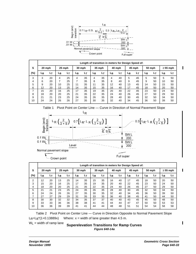
Superelevation Transitions for Ramp CurvesFigure 640-14a
Length of transition in meters for Design Speed of:
S 20 mph 25 mph 30 mph 35 mph 40 mph 45 mph 50 mph ≥ 55 mph
(%) LB LT LB LT LB LT LB LT LB LT LB LT LB LT LB LT
2 12 20 13 25 14 35 15 35 16 40 17 45 18 50 20 503 15 20 16 25 17 35 19 35 20 40 22 45 23 50 24 504 18 20 20 25 21 35 22 35 24 40 26 45 27 50 29 505 21 21 23 25 24 35 26 35 28 40 30 45 32 50 34 506 24 24 26 26 27 35 30 35 32 40 34 45 36 50 39 507 27 27 29 29 31 35 33 35 36 40 38 45 41 50 44 508 30 30 32 32 34 35 37 37 40 40 43 45 45 50 48 509 33 33 36 36 38 38 41 41 44 44 47 47 50 50 53 53
10 36 36 39 39 41 41 44 44 48 48 51 51 54 54 58 58
Table 2 Pivot Point on Center Line — Curve in Direction Opposite to Normal Pavement Slope
LR=LB*(1+0.13889x) Where: x = width of lane greater than 4.5 m.
WL = width of ramp lane
Length of transition in meters for Design Speed of:
S 20 mph 25 mph 30 mph 35 mph 40 mph 45 mph 50 mph ≥ 55 mph
(%) LB LT LB LT LB LT LB LT LB LT LB LT LB LT LB LT
3 3 20 4 25 4 35 4 35 4 40 5 45 5 50 5 504 6 20 7 25 7 35 8 35 8 40 9 45 9 50 10 505 9 20 10 25 11 35 11 35 12 40 13 45 14 50 15 506 12 20 13 25 14 35 15 35 16 40 17 45 18 50 20 507 15 20 16 25 17 35 19 35 20 40 22 45 23 50 24 508 18 20 20 25 21 35 22 35 24 40 26 45 27 50 29 509 21 21 23 25 24 35 26 35 28 40 30 45 32 50 34 50
10 24 24 26 26 27 35 30 35 32 40 34 45 36 50 39 50
Table 1 Pivot Point on Center Line — Curve in Direction of Normal Pavement Slope
Design Manual Geometric Cross SectionNovember 1999 Page 640-33
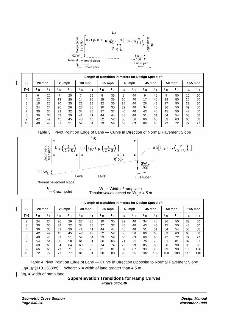
Length of transition in meters for Design Speed of:
S 20 mph 25 mph 30 mph 35 mph 40 mph 45 mph 50 mph ≥ 55 mph
(%) LB LT LB LT LB LT LB LT LB LT LB LT LB LT LB LT
3 6 20 7 25 7 35 8 35 8 40 9 45 9 50 10 504 12 20 13 25 14 35 15 35 16 40 17 45 18 50 20 505 18 20 20 25 21 35 22 35 24 40 26 45 27 50 29 506 24 24 26 26 27 35 30 35 32 40 34 45 36 50 39 507 30 30 32 32 34 35 37 37 40 40 43 45 45 50 48 508 36 36 39 39 41 41 44 44 48 48 51 51 54 54 58 589 42 42 45 45 48 48 52 52 56 56 60 60 63 63 68 68
10 48 48 51 51 54 54 59 59 63 63 68 68 72 72 77 77
Table 3 Pivot Point on Edge of Lane — Curve in Direction of Normal Pavement Slope
Superelevation Transitions for Ramp CurvesFigure 640-14b
Geometric Cross Section Design ManualPage 640-34 November 1999
Length of transition in meters for Design Speed of:
S 20 mph 25 mph 30 mph 35 mph 40 mph 45 mph 50 mph ≥ 55 mph
(%) LB LT LB LT LB LT LB LT LB LT LB LT LB LT LB LT
2 24 24 26 26 27 35 30 35 32 40 34 45 36 50 39 503 30 30 32 32 34 35 37 37 40 40 43 45 45 50 48 504 36 36 39 39 41 41 44 44 48 48 51 51 54 54 58 585 42 42 45 45 48 48 52 52 56 56 60 60 63 63 68 686 48 48 51 51 54 54 59 59 63 63 68 68 72 72 77 777 54 54 58 58 61 61 66 66 71 71 76 76 81 81 87 878 60 60 64 64 68 68 74 74 79 79 85 85 90 90 96 969 66 66 71 71 75 75 81 81 87 87 93 93 99 99 106 106
10 72 72 77 77 81 81 88 88 95 95 102 102 108 108 116 116
Table 4 Pivot Point on Edge of Lane — Curve in Direction Opposite to Normal Pavement Slope
LR=LB*(1+0.13889x) Where: x = width of lane greater than 4.5 m.
WL = width of ramp lane

When a new crest vertical curve is built or anexisting one is rebuilt, provide Design StoppingSight Distance from Figure 650-2. An existingcrest vertical curve with Existing Stopping SightDistance from Figure 650-3 may remain in place.
(4) Sag Vertical CurvesUse Figure 650-8 to find the minimum length fora sag vertical curve when given the stopping sightdistance and the algebraic difference in grades.The minimum length for a sag vertical curve canalso be determined by multiplying the algebraicdifference in grades by the KS value from Figure650-2 for design or 650-3 for existing (L=KS*A).Both the figure and the equation give approxi-mately the same length of curve. Neither thefigure nor the equation uses the sight distancegreater than the length of curve equation. Whenthe sight distance is greater than the length ofcurve and the length of curve is critical, the S>Lequation given on Figure 650-8 may be used tofind the minimum length of curve.
When a new sag vertical curve is built or anexisting one is rebuilt, provide Design StoppingSight Distance from Figure 650-2. An existingsag vertical curve with Existing Stopping SightDistance from Figure 650-3 may remain in place.
(5) Horizontal CurvesUse Figure 650-9 to check for adequate stoppingsight distance where sight obstructions are onthe inside of a curve. A stopping sight distanceobstruction is any object 610 mm or greaterabove the roadway surface (such as medianbarrier, guardrail, bridges, walls, cut slopes,wooded areas, and buildings). Figure 650-9 (boththe equation and the graph) are for use when thelength of curve is greater than the sight distanceand the sight restriction is more than half thesight distance from the end of the curve. Whenthe length of curve is less than the stopping sightdistance or the sight restriction is less than halfthe stopping sight distance into the curve, thedesired sight distance may be available with alesser M distance. When this occurs, the sightdistance can be checked graphically.
Provide Design Stopping Sight Distance fromFigure 650-2 for horizontal curves as follows:
• For all new roadways
• When the roadway is widened
• When there is an alignment shift
• For new features (such as median barrier,bridges, walls, or guardrail)
• When additional right of way is requiredfor roadside improvements
When design stopping sight distance is notrequired, existing features that have ExistingStopping Sight Distance from Figure 650-3,may remain in place.
650.06 Decision Sight DistanceDecision sight distance values are greater thanstopping sight distance values because they givethe driver an additional margin for error andafford sufficient length to maneuver at the sameor reduced speed rather than to just stop.
Provide decision sight distance where highwayfeatures create a likelihood for error in informa-tion reception, decision making, or controlactions. Example highway features includeinterchanges and intersections; changes in crosssection at toll plazas, drop lanes, etc.; and areasof concentrated demand where sources of infor-mation compete, as those from roadwayelements, traffic, traffic control devices, andadvertising signs. If possible, locate these high-way features where decision sight distance canbe provided. If this is not possible, use suitabletraffic control devices and positive guidance togive advanced warning of the conditions.
Use the decision sight distances in Figure 650-5where highway features require complexdriving decisions.
Sight Distance Design ManualPage 650-4 November 1999

anchor with the Weak Post Intersection Design.(See 710.06(4) Cases 12 and 13.) The Type 7anchor is used to develop tensile strength in themiddle of a guardrail run when the guardrailcurves and weak posts are used. (See 710.06(4)cases 9, 12, and 13.)
Locations where crossroads and driveways causegaps in the guardrail require special consider-ation. Elimination of the need for the barrier isthe preferred solution. Otherwise, a barrier flaremay be required to provide sight distance. If theslope is 1:2 or flatter and there are no hazards onor at the bottom of the slope, a terminal can beused to end the rail. Place the anchor of thisinstallation as close as possible to the roadapproach radius PC. If there is a hazard at or nearthe bottom of the slope that cannot be mitigated,then the Weak Post Intersection Design (see710.04(4) and the Standard Plans) can be used.This system can also be used at locations where acrossroad or road approach is near the end of abridge and installing a standard bridge approachguardrail placement (guardrail transition andterminal) is not possible.
(e) Evaluating Existing Terminals. Thereare several older terminal designs that may beencountered on our highways. The predominantterminal on our highways is the Breakaway CableTerminal (BCT). This system used a parabolicflare similar to the SRT with a Type 1 anchor.Type 1 anchor posts are wood set in a steel tubeor a concrete foundation.
BCTs that have at least a 1 m offset may remainin place unless the guardrail run or anchor isbeing reconstructed or reset. (Raising the railelement is not considered reconstructionor resetting.) BCTs with less than a 1 m offsetmust be replaced.
Replace existing buried terminals that slope downsuch that the guardrail height is reduced to lessthan 600 mm.
Replace guardrail ends that do not have a crash-worthy design with a crash worthy guardrailterminal. Common features of noncrashworthydesigns are as follows:
• No cable anchor.
• A cable anchored into concrete in front ofthe first post.
• Second post not breakaway (CRT).
• Design A end section (Design C end sectionsare acceptable to be left in place).
• Beam guardrail on both sides of the posts(two sided).
The old Type 3 anchor, which was primarily usedat bridge ends. (See Figure 710-5.) This anchorconsisted of a steel pipe mounted vertically in aconcrete foundation. Bridge approach guardrailwas then mounted on the steel pipe. On one-wayhighways, these anchors were usually positionedso that neither the anchor nor the bridge railposed a snagging hazard. In these cases, theanchor may remain in place if a stiffened transi-tion section is provided at the connection to thepost. On two-way highways the anchor maypresent a snagging hazard. In these cases, install aconnection from the anchor to the bridge rail ifthe offset from the bridge rail to the face of theguardrail is 460 mm or less. If the offset is greaterthan 460 mm, remove the anchor and install anew transition and connection.
Old Type 3 AnchorFigure 710-5
(3) Transitions and ConnectionsWhen there is an abrupt change from one barriertype to a more rigid barrier type, a vehicle hittingthe more flexible barrier is likely to be caught inthe deflected barrier pocket and directed into themore rigid barrier. This is commonly referred toas pocketing. A transition stiffens the moreflexible barrier by decreasing the post spacing,increasing the post size, and using stiffer beamelements to eliminate the possibility of pocketing.
Design Manual Traffic BarriersNovember 1999 Page 710-7

Design Manual SigningNovember 1999 Page 820-1
820 Signing
(basic design level) or “EU” (evaluate upgrade)matrix designation by applying the followingcriteria to determine the need to replace ormodify existing signs:
• Lack of nighttime retroreflectivity.
• Substantial damage, vandalism, ordeterioration.
• Age of signs (seven to ten years old).
• A change in sign use policy.
• Improper location.
• Message or destination changes necessaryto satisfy commitments to public or localagencies.
• Substandard mounting height.
• Change in jurisdiction, for example a countyroad becomes a state route.
Address sign support breakaway features whenidentified in the “Clear Zone” columns of theMatrices. When the “F” (full design level) matrixdesignation is present, the preceding criteria arestill applicable and all existing signing is requiredto conform to the current policy for reflectivesign sheeting requirements. Remove or replacesigning not conforming to this policy.
820.02 ReferencesRevised Code of Washington (RCW) 47.36.030,Traffic control devices
Manual on Uniform Traffic Control Devicesfor Streets and Highways (MUTCD), USDOT,Washington DC, 1988, including the WashingtonState Modifications to the MUTCD, M 24-01,WSDOT, 1996
Traffic Manual, M 51-02, WSDOT
Sign Fabrication Manual, M 55-05, WSDOT
Standard Plans for Road, Bridge, and MunicipalConstruction (Standard Plans), M 21-01,WSDOT
820.01 General820.02 References820.03 Design Components820.04 Overhead Installation820.05 Mileposts820.06 Guide Sign Plan820.07 Documentation
820.01 General
Signing is a primary mechanism for regulating,warning, and guiding traffic. Signing must bein place when any section of highway is open tothe motoring public. Each highway project hasunique and specific signing requirements. Forstatewide signing uniformity and continuity, it issometimes necessary to provide signing beyondthe project limits. Design characteristics of thefacility determine the size and legend for a sign.As the design speed increases, larger sign sizesare necessary to provide adequate messagecomprehension time. The MUTCD, the TrafficManual, and the Sign Fabrication Manualcontain standard sign dimensions, specificlegends, and reflective sheeting types for allnew signs. Guide signing provides the motoristwith guidance to destinations. This informationis always presented in a consistent manner. Insome cases, there are specific laws, regulations,and policies governing the content of the mes-sages on these signs. All proposed guide signsfor a project require the approval of the region’sTraffic Engineer. The use of nonstandard signsis strongly discouraged and their use requiresthe approval of the State Traffic Engineer.
The Design Matrices identify the design levelsfor signing on all preservation and improvementprojects. These levels are indicated in the column“Signing” for Interstate main line and the column“Signing, Delineation, and Illumination” for allother routes.
Review and update existing signing within thelimits of all preservation and improvementprojects as indicated in the matrices. Providestandard signing on projects with either a “B”

Signing Design ManualPage 820-2 November 1999
Standard Specifications for Road, Bridge, andMunicipal Construction (Standard Specifica-tions), M 41-10, WSDOT
Plans Preparation Manual, M 22-31, WSDOT
Directive D 32-20, “State Route Mileposts,”WSDOT
820.03 Design Components(1) LocationThe MUTCD contains the guidelines for posi-tioning signs. Check sign locations to ensure thatthe motorist’s view of the sign is not obscured byother roadside appurtenances. Also, determine ifthe proposed sign will obstruct the view of othersigns or limit the motorist’s sight distance of theroadway. Reposition existing signs, when neces-sary, to satisfy these visibility requirements.Where possible, locate signs behind existingtraffic barriers, on grade separation structures,or where terrain features will minimize theirexposure to errant vehicles.
(2) Longitudinal PlacementThe MUTCD and the Traffic Manual provideguidelines for the longitudinal placement of signsthat are dependent on the type of sign. Select alocation to fit the existing conditions to ensurevisibility and adequate response time. In mostcases, signs can be shifted longitudinally toenhance safety without compromising theirintended purpose.
(3) Lateral ClearanceThe MUTCD contains minimum requirementsfor the lateral placement of signs. These require-ments are shown in Figures 820-1a and 820-1b.When possible, position the signs at the maxi-mum practical lateral clearance for safety andreduced maintenance costs. Locate large guidesigns and motorist information signs beyond theDesign Clear Zone, when limited right of wayor other physical constraints are not a factor.See Chapter 700. On steep fill slopes, an errantvehicle is likely to be partially airborne from theslope break near the edge of shoulder to a point3.6 m down the slope. When signs are placed onfill slopes steeper than 1:6, locate the support at
least 3.6 m beyond the slope break. Usebreakaway sign support features, when required,for signs located within the Design Clear Zoneand for signs located beyond this zone wherethere is a possibility they might be struck byan errant vehicle. Breakaway features are notnecessary on sign posts located behind trafficbarriers. Install longitudinal barrier to shield signswithout breakaway features within the DesignClear Zone when no other options are available.
Sign bridges and cantilever sign structures havelimited span lengths. Locate the vertical compo-nents of these structures as far from the traveledway as possible and, where appropriate, installtraffic barriers or land forms. See Chapter 710.
Do not locate sign posts in the bottom of a ditchor where the posts will straddle the ditch. Thepreferred location is beyond the ditch or on theditch backslope. In high fill areas, where condi-tions require placement of a sign behind a trafficbarrier, consider adding embankment material toreduce the length of the sign supports.
(4) Sign HeightsFor ground-mounted signs installed at the sideof the road, provide a mounting height of at least2.1 m, measured from the bottom of the sign tothe edge of traveled way. Supplemental plaques,when used, are mounted directly below theprimary sign. At these locations, the minimummounting height of the plaque is 1.5 m.
Do not attach supplemental guide signs to theposts below the hinge mechanism or saw cutnotch on multiple post installations. The locationof these hinges or saw cuts on the sign supportsare shown in the Standard Plans.
A minimum 2.1 m vertical height from thebottom of the sign to the ground directly belowthe sign is necessary for the breakaway featuresof the sign support to function properly whenstruck by a vehicle. The minimum mountingheight for new signs located behind longitudinalbarriers is 2.1 m, measured from the bottom ofthe sign to the edge of traveled way. A lowermounting height of 1.5 m may be used whenreplacing a sign panel on an existing signassembly located behind longitudinal barrier.
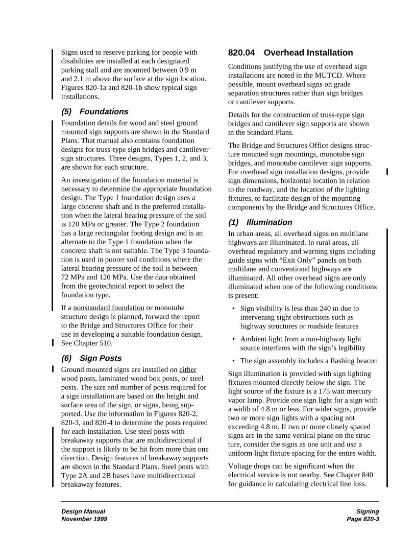
Design Manual SigningNovember 1999 Page 820-3
Signs used to reserve parking for people withdisabilities are installed at each designatedparking stall and are mounted between 0.9 mand 2.1 m above the surface at the sign location.Figures 820-1a and 820-1b show typical signinstallations.
(5) FoundationsFoundation details for wood and steel groundmounted sign supports are shown in the StandardPlans. That manual also contains foundationdesigns for truss-type sign bridges and cantileversign structures. Three designs, Types 1, 2, and 3,are shown for each structure.
An investigation of the foundation material isnecessary to determine the appropriate foundationdesign. The Type 1 foundation design uses alarge concrete shaft and is the preferred installa-tion when the lateral bearing pressure of the soilis 120 MPa or greater. The Type 2 foundationhas a large rectangular footing design and is analternate to the Type 1 foundation when theconcrete shaft is not suitable. The Type 3 founda-tion is used in poorer soil conditions where thelateral bearing pressure of the soil is between72 MPa and 120 MPa. Use the data obtainedfrom the geotechnical report to select thefoundation type.
If a nonstandard foundation or monotubestructure design is planned, forward the reportto the Bridge and Structures Office for theiruse in developing a suitable foundation design.See Chapter 510.
(6) Sign PostsGround mounted signs are installed on eitherwood posts, laminated wood box posts, or steelposts. The size and number of posts required fora sign installation are based on the height andsurface area of the sign, or signs, being sup-ported. Use the information in Figures 820-2,820-3, and 820-4 to determine the posts requiredfor each installation. Use steel posts withbreakaway supports that are multidirectional ifthe support is likely to be hit from more than onedirection. Design features of breakaway supportsare shown in the Standard Plans. Steel posts withType 2A and 2B bases have multidirectionalbreakaway features.
820.04 Overhead Installation
Conditions justifying the use of overhead signinstallations are noted in the MUTCD. Wherepossible, mount overhead signs on gradeseparation structures rather than sign bridgesor cantilever supports.
Details for the construction of truss-type signbridges and cantilever sign supports are shownin the Standard Plans.
The Bridge and Structures Office designs struc-ture mounted sign mountings, monotube signbridges, and monotube cantilever sign supports.For overhead sign installation designs, providesign dimensions, horizontal location in relationto the roadway, and the location of the lightingfixtures, to facilitate design of the mountingcomponents by the Bridge and Structures Office.
(1) IlluminationIn urban areas, all overhead signs on multilanehighways are illuminated. In rural areas, alloverhead regulatory and warning signs includingguide signs with “Exit Only” panels on bothmultilane and conventional highways areilluminated. All other overhead signs are onlyilluminated when one of the following conditionsis present:
• Sign visibility is less than 240 m due tointervening sight obstructions such ashighway structures or roadside features
• Ambient light from a non-highway lightsource interferes with the sign’s legibility
• The sign assembly includes a flashing beacon
Sign illumination is provided with sign lightingfixtures mounted directly below the sign. Thelight source of the fixture is a 175 watt mercuryvapor lamp. Provide one sign light for a sign witha width of 4.8 m or less. For wider signs, providetwo or more sign lights with a spacing notexceeding 4.8 m. If two or more closely spacedsigns are in the same vertical plane on the struc-ture, consider the signs as one unit and use auniform light fixture spacing for the entire width.
Voltage drops can be significant when theelectrical service is not nearby. See Chapter 840for guidance in calculating electrical line loss.

Signing Design ManualPage 820-4 November 1999
In areas where an electrical power source is morethan 800 m away, utility company installationcosts can be prohibitive. Reconsider the benefitof an overhead sign installation at these locations.
(2) Vertical ClearanceThe minimum vertical clearance from the road-way surface to the lowest point of an overheadsign assembly is 5.3 m. The maximum clearanceis 6.4 m.
(3) Horizontal PlacementConsider roadway geometrics and anticipatedtraffic characteristics in order to locate signsabove the lane, or lanes, to which they apply.Install advance guide signs and exit directionsigns that require an EXIT ONLY and “downarrow” panel directly above the drop lanes.To reduce driver confusion as to which laneis being dropped, avoid locating a sign withan EXIT ONLY panel on a horizontal curve.
(4) Service WalkwaysWalkways are provided on structure-mountedsigns, truss-type sign bridges, and truss-typecantilever sign supports where the roadwayand traffic conditions prohibit normal signmaintenance activities. Normally, monotubesign bridges and cantilever sign supports donot have service walkways.
Vandalism of signs, particularly in the form ofgraffiti, can be a major problem in some areas.Vandals sometimes use the service walkways.Maintenance costs in cleaning or replacingvandalized signs at these locations can exceedthe benefit of providing the service walkway.
820.05 MilepostsMilepost markers are a part of a statewide systemfor all state highways and are installed in accor-dance with the Directive D 32-20, State RouteMileposts.
820.06 Guide Sign PlanA guide sign plan is used by the region to identifyexisting and proposed guide signing on statehighways. The plan provides an easily understoodgraphic representation of the signing and allowsassessment of the continuity in signing to motor-ist destinations, activities, and services. It is alsoused to identify deficiencies or poorly definedroutes of travel. A guide sign plan for safety andmobility improvement projects is desirable.When proposed highway work affects signingto a city or town, the guide sign plan can befurnished to the official governing body forreview and consideration. The guide sign planis reviewed and approved by the region’s TrafficEngineer.
820.07 DocumentationInclude the following items in the project file:
o An inventory of all existing signing withinthe project limits
o Approval of proposed guide signs
o Approval of non-standard signs
o Soils investigations for all sign bridge andcantilever sign supports

Design Manual SigningNovember 1999 Page 820-5
Sign Support LocationsFigure 820-1a
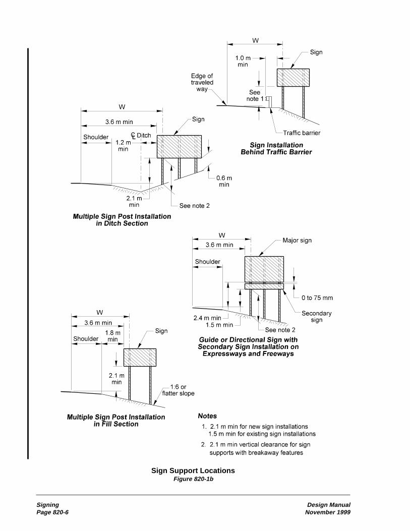
Signing Design ManualPage 820-6 November 1999
Sign Support LocationsFigure 820-1b
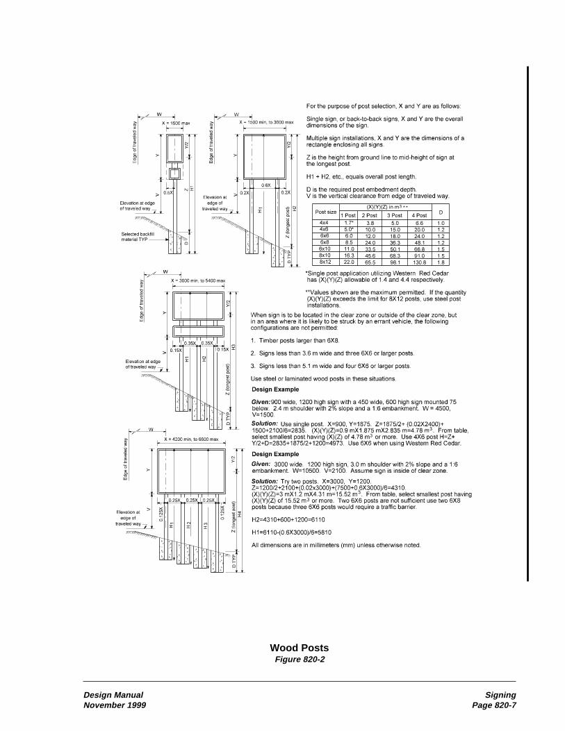
Design Manual SigningNovember 1999 Page 820-7
Wood PostsFigure 820-2
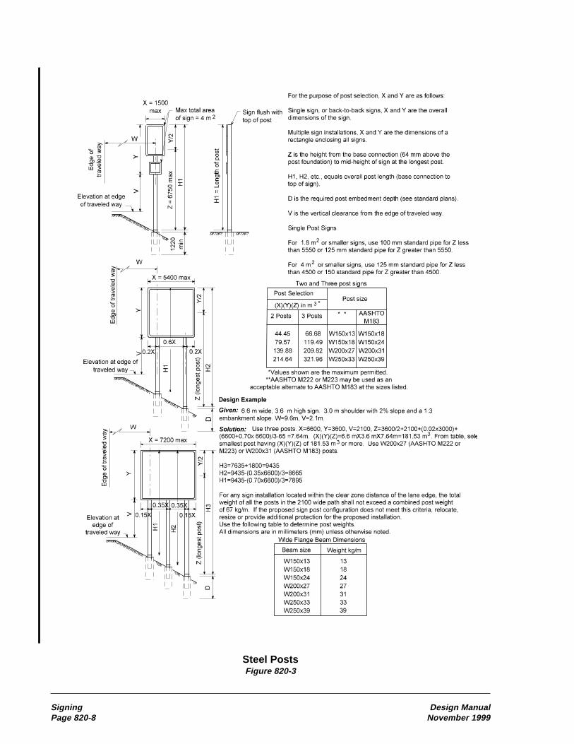
Signing Design ManualPage 820-8 November 1999
Steel PostsFigure 820-3

Design Manual SigningNovember 1999 Page 820-9
Laminated Wood Box PostsFigure 820-4

Design Manual Intelligent Transportation SystemsNovember 1999 Page 860-1
860 Intelligent Transportation Systems
• The Greater Puget Sound Region
• The Spokane Area
• The Vancouver Area
• Other Statewide Urban Areas
• Rural Areas and Intercity Corridors
An intelligent transportation system can beimplemented in stages, starting with a smallproject for immediate benefit and then expandingthe system as needed. Consider installing an ITSat any of the following locations:
• Where congestion frequently causesaccidents.
• At freeway on-ramps where merging prob-lems routinely occur.
• Where heavy traffic volumes occur betweenclosely spaced on-ramps.
• Where the motorist would benefit frominformation on traffic conditions oralternative routes.
The initial stage of an intelligent transportationsystem can be as simple as installing a dynamicmessage sign that warns motorists of unusualdriving conditions. Appropriate messages can bedisplayed on the sign using information obtainedby direct observation of road conditions or byreports from law enforcement agencies.
Automated systems incorporate a traffic datacollection system. The data collection systemprovides basic data to determine traffic volumes,vehicular speeds, and levels of congestion. Thetraffic data can be analyzed and used to verify thelocations of traffic problems. This data can alsobe used in freeway computer models to predictthe impacts of proposed improvements.
Design each stage of the system so that theassociated technology can be used in subsequent,more sophisticated stages. For example, the stagefollowing data collection could be the installationof closed circuit television cameras (CCTV) to
860.01 General860.02 References860.03 Traffic Data Collection860.04 Traffic Flow Control860.05 Motorist information860.06 Documentation
860.01 GeneralIntelligent Transportation Systems (ITS) applyadvanced technologies in communications andcomputer science to optimize the safety andefficiency of the existing surface transportationnetwork. In highway design, this goal is achievedby collecting and using traffic data to developpredictive models, regulating access to thefreeway system, and providing timely informa-tion on traffic conditions to motorists. Previously,this technology was called Surveillance, Control,and Driver Information (SC&DI). In the contextof highway design, ITS and SC&DI are synony-mous.
The Transportation Equity Act (TEA-21) requiresITS projects to comply with the standards beingdeveloped in association with the federal govern-ment and private industry. These standards willbe known as the National ITS Architecture.These standards are intended to ensureinteroperability and efficiency to the maximumextent practicable for the many different typesof ITS devices under development. The NationalITS Architecture organizes a “system of sub-systems” and makes managing ITS deploymenteasier. The Architecture helps agencies commu-nicate complex ideas by providing a commonlanguage and definitions. One benefit of using theNational ITS Architecture is that it helps identifyall agencies and jurisdictions that should beincluded in ITS projects.
The ITS program in Washington State is knownas “Venture Washington.” It focuses on fiveareas within Washington State. These areas werechosen because they each have unique character-istics and problems associated with traffic. Thesefive areas are:
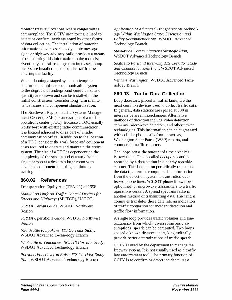
Intelligent Transportation Systems Design ManualPage 860-2 November 1999
monitor freeway locations where congestion iscommonplace. The CCTV monitoring is used todetect or confirm incidents noted by other formsof data collection. The installation of motoristinformation devices such as dynamic messagesigns or highway advisory radio provides a meansof transmitting this information to the motorist.Eventually, as traffic congestion increases, rampmeters are installed to control the traffic flowentering the facility.
When planning a staged system, attempt todetermine the ultimate communication systemto the degree that underground conduit size andquantity are known and can be installed in theinitial construction. Consider long-term mainte-nance issues and component standardization.
The Northwest Region Traffic Systems Manage-ment Center (TSMC) is an example of a trafficoperations center (TOC). Because a TOC usuallyworks best with existing radio communication,it is located adjacent to or as part of a radiocommunication office. In addition to the locationof a TOC, consider the work force and equipmentcosts required to operate and maintain the entiresystem. The size of a TOC is dependent on thecomplexity of the system and can vary from asingle person at a desk to a large room withadvanced equipment requiring continuousstaffing.
860.02 ReferencesTransportation Equity Act (TEA-21) of 1998
Manual on Uniform Traffic Control Devices forStreets and Highways (MUTCD), USDOT,
SC&DI Design Guide, WSDOT NorthwestRegion
SC&DI Operations Guide, WSDOT NorthwestRegion
I-90 Seattle to Spokane, ITS Corridor Study,WSDOT Advanced Technology Branch
I-5 Seattle to Vancouver, BC, ITS Corridor Study,WSDOT Advanced Technology Branch
Portland/Vancouver to Boise, ITS Corridor StudyPlan, WSDOT Advanced Technology Branch
Application of Advanced Transportation Technol-ogy Within Washington State: Discussion andPolicy Recommendations, WSDOT AdvancedTechnology Branch
State-Wide Communications Strategic Plan,WSDOT Advanced Technology Branch
Seattle to Portland Inter-City ITS Corridor Studyand Communications Plan, WSDOT AdvancedTechnology Branch
Venture Washington, WSDOT Advanced Tech-nology Branch
860.03 Traffic Data CollectionLoop detectors, placed in traffic lanes, are themost common devices used to collect traffic data.In general, data stations are spaced at 800 mintervals between interchanges. Alternativemethods of detection include video detectioncameras, microwave detectors, and other newertechnologies. This information can be augmentedwith cellular phone calls from motorists,Washington State Patrol (WSP) reports, andcommercial traffic reporters.
The loops sense the amount of time a vehicleis over them. This is called occupancy and isrecorded by a data station in a nearby roadsidecabinet. The data station periodically transmitsthe data to a central computer. The informationfrom the detection system is transmitted overleased phone lines, WSDOT phone lines, fiberoptic lines, or microwave transmitters to a trafficoperations center. A spread spectrum radio isanother method of transmitting data. The centralcomputer translates these data into an indicationof traffic congestion for incident detection andtraffic flow information.
A single loop provides traffic volumes and laneoccupancy from which, given some basic as-sumptions, speeds can be computed. Two loopsspaced a known distance apart, longitudinally,provide better determinations of traffic speeds.
CCTV is used by the department to manage thefreeway system. It is not usually used as a trafficlaw enforcement tool. The primary function ofCCTV is to confirm or detect incidents. As a

Design Manual Intelligent Transportation SystemsNovember 1999 Page 860-3
secondary function, this information can beprovided to the WSP, incident response teams,maintenance forces, and the local media.
860.04 Traffic Flow ControlDuring peak traffic volume periods, freeway on-ramps are metered with either roadside oroverhead traffic signals. These ramp meterscontrol or regulate the flow of traffic enteringthe freeway. The metering prevents the enteringtraffic from exceeding freeway capacity bylimiting the number of vehicles that enter withina specific time period. The meters also keep longplatoons of cars from merging onto the freeway.This process makes on-ramp merges safer andallows freeway traffic to move at a more efficientspeed.
Ramp meters are traffic control signals and anapproved traffic signal permit is required. Theapproval procedures for traffic signal permits arenoted in Chapter 850.
Consider the available area for vehicle storageon the ramp when locating a ramp meter. If thearrival rate of the entering traffic exceeds themetered flow rate, traffic queues will develop. Acommon concern is that this queue might extendonto the crossroads and interfere with localtraffic. Chapter 1050 provides guidance on theplacement of the ramp meter. This guidance,however, only addresses the required accelerationneeded to merge onto the freeway. The storagearea needed at the meter varies at each locationand is determined separately. If it is not possibleto provide an adequate storage length on theramp, consider alternate methods of addressingthe problem.
(1) Adjust the ramp metering rate totemporarily increase the rate.
(2) Allow two vehicles to pass the meter ata time.
(3) Widen to two metered lanes.
(4) Provide storage lanes on the crossroad.
(5) Provide alternate routes for local traffic.
(6) Provide HOV bypass lanes.
(1) Adjust Rate. Ramp metering uses informa-tion from the detection loops to determinefreeway congestion adjacent to and downstreamfrom the ramps. Data from the loops are sent to acentral computer or a local computer that adjuststhe metering rate for the traffic congestion andtransmits this rate to the ramp meter controllers.The ramp controllers implement the metering rateand control the signal. A ramp metering rate canbe determined in two ways: remote metering andstandby metering.
For remote metering, the metering rates of allramp meter locations are determined by the localcontroller and adjusted by the central computer atthe TOC. This is the normal mode of operationfor the Seattle system. The central computer iscapable of adjusting upstream metering rates onthe basis of downstream conditions. A meteringrate at an upstream location is decreased if trafficcongestion develops downstream. Metering startand end times, as well as metering rates, can beremotely adjusted from the TOC with an overridefunction.
Standby metering, also called local control, isused when communications with the centralcomputer are interrupted or when that computeris not in service. In these cases, each ramp meterdetermines a metering rate for its on-rampaccording to local traffic conditions or by a pre-determined rate based on a time of day table.These time of day tables are developed to predictaverages of the actual traffic volume peakingcharacteristics of the on-ramp. In standby meter-ing, each ramp meter operates independentlywithout coordinating with other controllers.
Single lane metering rates normally vary between4 and 15 vehicles per minute (240 and 900vehicles per hour). If a ramp has heavier trafficvolumes and queue storage is not adequate,several actions can be taken.
(2) Two Vehicles. The metering capacity canbe increased by allowing two vehicles to enterduring each green cycle. This can increase asingle lane ramp meter maximum capacity toabout 1,100 vehicles per hour. This procedureis a temporary, operational solution and is not arecommended design practice.

Intelligent Transportation Systems Design ManualPage 860-4 November 1999
(3) Widen. The metering capacity can be in-creased by widening the ramp to install additionallanes. Widening a single-lane on-ramp to createtwo lanes can double the metered traffic volumeto 1,800 vehicles per hour, provided no down-stream traffic congestion develops. Changes inramp access to the freeway might require anaccess point decision report. (See Chapter 1425.)
(4) Storage Lanes. If adequate storage lengthcannot be provided on the ramp, it might bepossible to provide storage as turn lanes on thecrossroad and adjust the ramp terminal trafficsignal timing to limit freeway access movements.
(5) Diversion. Diversion of some ramp trafficto local arterial streets might can be desirable,assuming a suitable alternate route is available.When diversion occurs, modification of trafficsignal timing and coordination plans on thealternative routes might be necessary. Coordinateefforts with the local agency and, if appropriate,initiate public meetings to identify needs andimpacts.
(6) HOV Bypass. Wherever possible, providebypass lanes for high occupancy vehicles (HOV)around the traffic queue at the ramp meter. TheHOV bypass allows transit vehicles to maintainschedules and indirectly provides an incentivefor carpooling. (See Chapter 1050.)
860.05 Motorist InformationMotorist information includes dynamic messagesigns, highway advisory radio, telephone trafficinformation lines, commercial radio and televi-sion messages, and Internet access for personalcomputers. These are all used to transmit trafficconditions to freeway users. The motorist infor-mation system is also used to alert drivers to shortterm construction and maintenance activities thatmight affect normal travel patterns. It can also beused to suggest alternative travel routes.
(1) Dynamic Message SignsDynamic message signs (DMS) are used toprovide motorists with current road and trafficconditions. Accidents, incidents, construction andmaintenance activities, reversible lane status,traffic congestion, and traction device require-
ments are examples of this information. Becausemotorists receive many distractions while driv-ing, consider the location of the DMS. The bestlocation for a DMS is on a tangent section ofroadway with few roadside distractions. Over-head installations have more visual impact. Whenpossible, use sign bridges, cantilever sign struc-tures, or bridge mounts on existing overcrossingsfor DMSs. Use the message displays and signlocation requirements contained in the Manual onUniform Traffic Control Devices for Streets andHighways (MUTCD) and Chapter 820.
(2) Highway Advisory RadioThe highway advisory radio (HAR) system usescar radios to provide information to motorists.Warning signs, usually with flashing beacons,direct motorists to select a specific AM radiostation for information. HAR has an advantageover DMS because longer messages with moredetailed information can be relayed to the motor-ist. The major disadvantages are that not allvehicles have radios that can receive HARfrequencies, and some motorists might not usethe radio for this information. HAR works bestwhen used in conjunction with DMS.
HAR locations and assigned radio frequenciesare restricted to prevent interference with otherfrequencies in use. HAR message content isrestricted by federal regulations and WSDOTrestricts HAR messages to noncommercial voiceinformation pertaining to roadway and mountainpass conditions, major incidents, traffic hazards,and travel advisories.
(3) Additional Public InformationComponentsA telephone number can be provided to give thesame prerecorded messages as the HAR and canalso include transit and carpool information. Acomputer generated flow map can be developed,using the data collection system, to graphicallydepict actual traffic flows within a geographicalarea. The flow map can be made accessible to thepublic by providing links to a WSDOT web site.

Design Manual Intelligent Transportation SystemsNovember 1999 Page 860-5
860.06 Documentation
Preserve the following documents in the projectfile: See Chapter 330.
o Justification for the installation oframp meters.
o Approved traffic signal permit forramp meters.
o All correspondence and coordinationwith local agencies.
o Designs for the ultimate system whenstaged implementation is used.
P65:DP/DMM

Left-Turn Storage LengthFigure 910-9a
Design Manual Intersections At GradeNovember 1999 Page 910-17

Left-Turn Storage LengthFigure 910-9b
Intersections At Grade Design ManualPage 910-18 November 1999

Left-Turn Storage LengthFigure 910-9c
Design Manual Intersections At GradeNovember 1999 Page 910-19
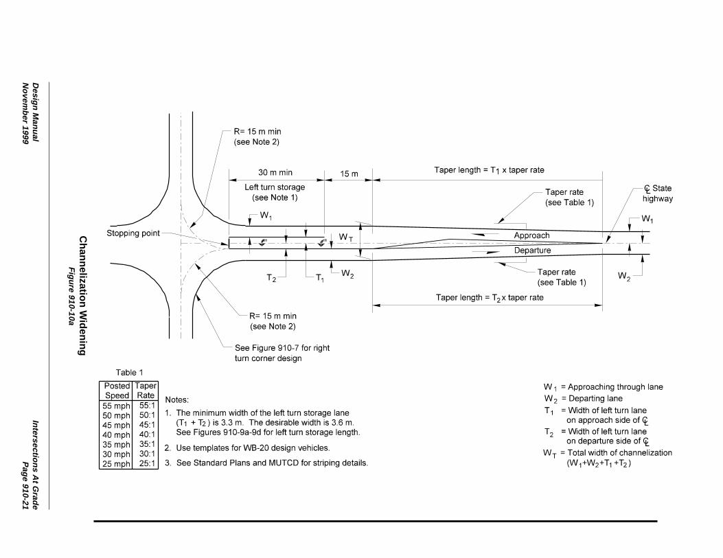
Channelization W
ideningF
igure 910-10a
Design M
anualIntersections A
t Grade
Novem
ber 1999P
age 910-21

Median C
hannelization — M
edian Width 7 m
to 8 mF
igure 910-10b
Intersections At G
radeD
esign Manual
Page 910-22
Novem
ber 1999
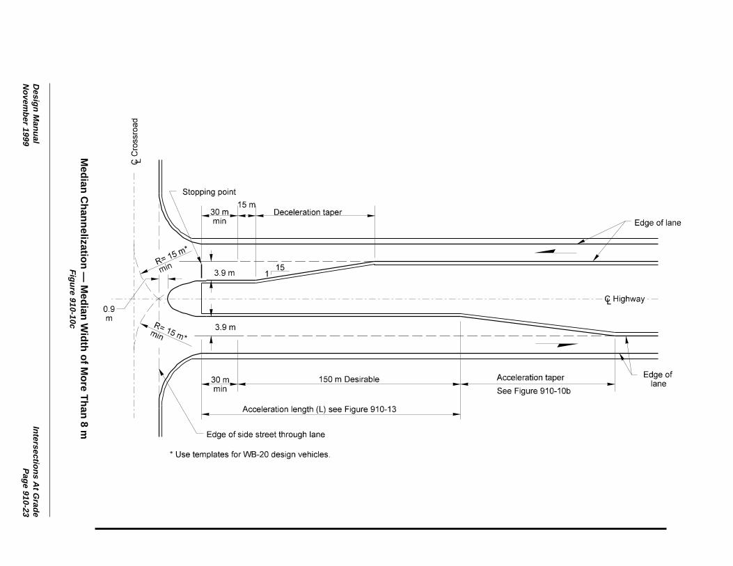
Median C
hannelization — M
edian Width of M
ore Than 8 m
Figure 910-10c
Design M
anualIntersections A
t Grade
Novem
ber 1999P
age 910-23

Minor Intersection on D
ivided Highw
ayF
igure 910-10d
Intersections At G
radeD
esign Manual
Page 910-24
Novem
ber 1999

U-Turn LocationsFigure 910-15
Design Manual Intersections At GradeNovember 1999 Page 910-33
Vehicle W R L F1 F2 Taper
P 15.6 4.2 4.2 3.6 3.6 —
SU 26.6 9.0 5.9 4.0 4.6 10:1
BUS 26.6 8.5 7.0 4.1 5.5 10:1
WB-12 25.4 7.5 8.0 4.4 6.2 6:1
WB-15 28.4 8.0 9.5 4.9 7.7 6:1
WB-20 28.4 6.8 14.8 4.5 10.5 6:1
MH 25.4 8.0 5.9 4.5 4.9 10:1
P/T 15.6 3.3 3.8 3.6 5.4 6:1
MH/B 31.4 11.0 6.5 4.5 5.0 10:1

Sight Distance for Grade Intersection With Stop ControlFigure 910-16a
Intersections At Grade Design ManualPage 910-34 November 1999
SD = Sight Distance
ta = Time for acceleration
V = Design speed on the through highway
L = Length of vehicle
X = Length of vehicle travel
L Values
P = 5.8 m
SU = 9.1 m
WB-15 = 16.7 m
WB-20 = 21.0 m
Note: If the crossroad is not level, multiply taby the adjustment factor to consider thegrade.
Sight Distance Adjustment Factor
Design Crossroad Grade, PercentVehicle -4 -2 0 +2 +4
P 0.7 0.9 1.0 1.1 1.3
SU 0.8 0.9 1.0 1.1 1.3
WB-12 0.8 0.9 1.0 1.2 1.7
Example
Given:Two - 3.6 m lanes to be crossed by a WB-15.Intersection angle approximately 90°.Through highway design speed = 70 mph
Find:The minimum required sight distance.
Solution:Xright = 3.0 + WR + L = 3.0 + 7.2 + 16.7 = 26.9 mXleft = 3.0 + WL + L = 3.0 + 3.6 + 16.7 = 23.3 m
From the charts as shown, the required minimum SD = 380 m right and 360 m left.

Sight Distance at IntersectionsFigure 910-16c
Intersections At Grade Design ManualPage 910-36 November 1999
For crest vertical curve over a curbwhere S<L:
( ) ( )[ ]S =
0.1L 2 H -HC 2 H -HC
A
1 22
+
( ) ( )[ ]L =
AS
0.1 2 H HC 2 H HC
2
1 22
− + −
Where:S = Available sight distance (m)
H1 = Eye height (1070 mm)
H2 = Object height (1300 mm)
HC = Curb height (mm)L = Vertical curve length (m)A = Algebraic difference in grades (%)
For bridge pier or bridge rail:
Where: S = Available sight distance (m) n = Offset from sight obstruction to edge of lane (m) x = Distance from center line of lane to sight obstruction (m)
( )S =
7.8 x
5.4 n−
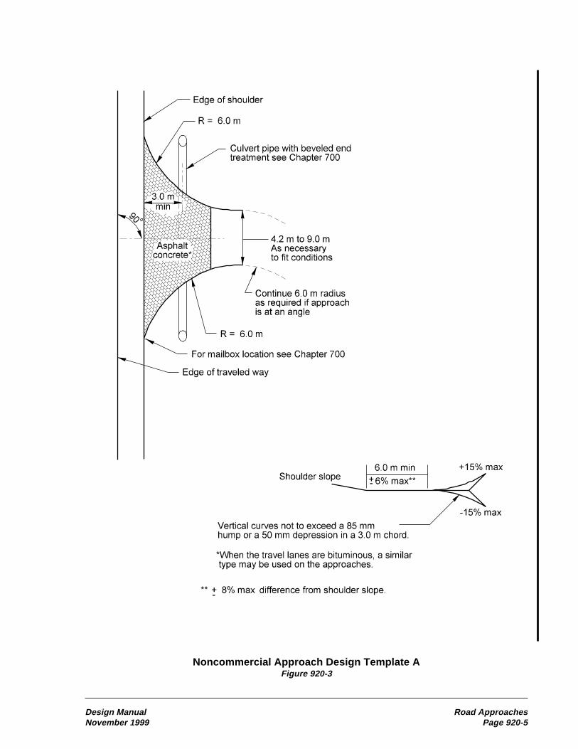
Noncommercial Approach Design Template AFigure 920-3
Design Manual Road ApproachesNovember 1999 Page 920-5

Noncommercial Approach Design Template B and CFigure 920-4
Road Approaches Design ManualPage 920-6 November 1999
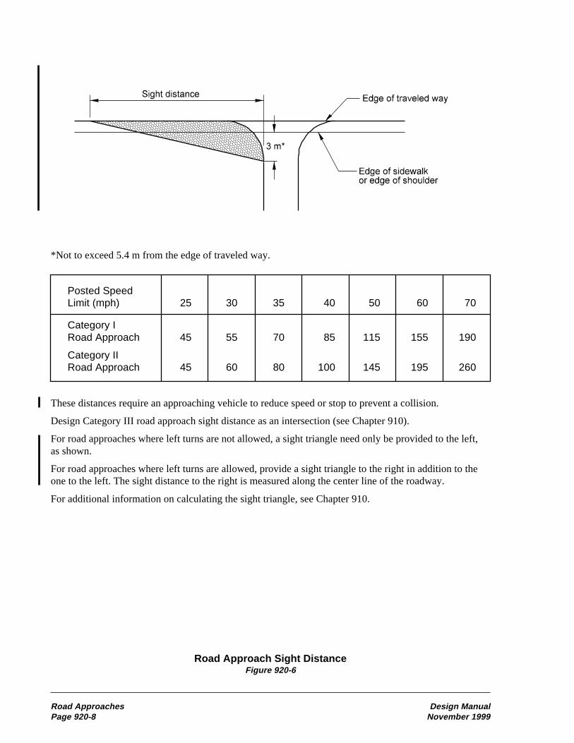
Road Approach Sight DistanceFigure 920-6
Road Approaches Design ManualPage 920-8 November 1999
*Not to exceed 5.4 m from the edge of traveled way.
Posted SpeedLimit (mph) 25 30 35 40 50 60 70
Category IRoad Approach 45 55 70 85 115 155 190
Category IIRoad Approach 45 60 80 100 145 195 260
These distances require an approaching vehicle to reduce speed or stop to prevent a collision.
Design Category III road approach sight distance as an intersection (see Chapter 910).
For road approaches where left turns are not allowed, a sight triangle need only be provided to the left,as shown.
For road approaches where left turns are allowed, provide a sight triangle to the right in addition to theone to the left. The sight distance to the right is measured along the center line of the roadway.
For additional information on calculating the sight triangle, see Chapter 910.

Road Approach Spacing and Corner ClearanceFigure 920-7
Design Manual Road ApproachesNovember 1999 Page 920-9
Highway AccessManagement Class 1 2 3 4 5
S 402.4 m 201.2 m 100.6 m 76.2 m 38.1 m
1320 ft 660 ft 330 ft 250 ft 125 ft
Road Approach Spacing and Corner Clearance
Note:
For Road Approach Spacing, S is the distance between closest edge of the traveled way of the two roadapproaches, measured along the edge of the traveled way of the highway.
For corner clearance, S is measured from the closest edge of the traveled way of the crossroad to theclosest edge of the traveled way of the road approach, measured along the edge of the traveled way ofthe highway.

Ramp Design 45 andSpeed (mph) 25-30 35-40 above
Desirable Grade (%) 5 4 3
Maximum Grade (%) 7 6 5
On one-way ramps down grades may be 2%greater.
Maximum Ramp GradeFigure 940-2
(4) Cross SectionProvide the minimum ramp widths given inFigure 940-3. Ramp traveled ways may requireadditional width to these minimums as one-wayturning roadways. See Chapter 640 for additionalinformation and roadway sections.
Number of Lanes 1 2
Traveled Way(1) 4.5(2) 7.5(3)
Shoulders Right 2.4 2.4Left 0.6 1.2
Medians(4) 1.8 1.8
(1)See Chapter 1050 for additional widthwhen an HOV lane is present.
(2)May be reduced to 3.6 on tangents.(3)Add 3.6 m for each additional lane.(4)In addition to shoulder width.
Ramp WidthsFigure 940-3
Cross slope and superelevation requirements forramp traveled way and shoulders are as given inChapter 640 for roadways.
Whenever feasible, make the ramp cross slope atthe ramp beginning or ending station equal to thecross slope of the through lane pavement. Wherespace is limited and superelevation runoff is longor when parallel connections are used, thesuperelevation transition may be ended beyond(for on-ramps) or begun in advance of (foroff-ramps) the ramp beginning or ending station,provided that the algebraic difference in cross
slope at the edge of the through lane and the crossslope of the ramp does not exceed 4%. In suchcases, ensure smooth transitions for the edge oftraveled way.
(5) Ramp Lane IncreasesWhen off-ramp traffic and left-turn movementsvolume at a crossroad terminal cause congestion,it may be desirable to add lanes to the ramp toreduce the queue length caused by turningconflicts. Make provision for the addition oframp lanes whenever ramp exit or entrancevolumes, after the design year, are expected toresult in poor service. See Chapter 620 for widthtransition design.
(6) Ramp MetersRamp meters are used to allow a measured orregulated amount of traffic to enter the freeway.When operating in the “measured” mode, theyrelease traffic at a measured rate to keep down-stream demand below capacity and improvesystem travel times. In the “regulated” mode,they break up platoons of vehicles that occurnaturally or result from nearby traffic signals.Even when operating at near capacity, a freewaymain line can accommodate merging vehicles oneor two at a time, while groups of vehicles willcause main line flow to break down.
The location of the ramp meter is a balancebetween the storage and acceleration require-ments. Locate the ramp meter to maximize theavailable storage and so that the acceleration lanelength, from a stop to the freeway main linedesign speed, is available from the stop bar to themerging point. With justification, the main linedesign speed may be reduced to the averagerunning speed during the hours of meter opera-tion. See 940.06(4) for information on the designof on-connection acceleration lanes. See Chapter860 for additional information on the design oframp meters.
Driver compliance with the signal is required forthe ramp meter to have the desired results.Consider enforcement areas with ramp meters.
Consider HOV bypass lanes with ramp meters.See Chapter 1050 for design data for ramp meterbypass lanes.
Design Manual Traffic InterchangesNovember 1999 Page 940-5

• Design and construct temporary ramps as ifthey were permanent unless second stageconstruction is planned to rapidly follow thefirst. In all cases, design the connection tomeet the safety needs of the traffic. (SeeFigure 940-16.)
940.09 Interchange PlansFigure 940-17 is a sample showing the generalformat and data required for interchange designplans.
Compass directions (W-S Ramp) or crossroadnames (E-C Street) may be used for ramp desig-nation to realize the most clarity for eachparticular interchange configuration and circum-stance.
Include the following as applicable:
• Classes of highway and design speeds formain line and crossroads (Chapter 440).
• Curve data on main line, ramps, andcrossroads.
• Numbers of lanes and widths of lanes andshoulders on main line, crossroads, andramps.
• Superelevation diagrams for the main line,the crossroad, and all ramps (may besubmitted on separate sheets).
• Channelization (Chapter 910).
• Stationing of ramp connections andchannelization.
• Proposed right of way and access controltreatment (Chapter 1420).
• Delineation of all crossroads, existing andrealigned (Chapter 910).
• Traffic data necessary to justify the proposeddesign. Include all movements.
Prepare a preliminary contour grading plan foreach completed interchange. Show the desiredcontours of the completed interchange includingdetails of basic land formation, slopes, gradedareas or other special features. Coordinate thecontour grading with the drainage design andthe roadside development plan.
Alternative designs considered, studied, andrejected may be shown as reduced scale diagramswith a brief explanation of the advantages anddisadvantages of the alternative designs,including the recommended design.
940.10 DocumentationThe following documents are to be preserved inthe project file. See Chapter 330.
o Interchange plan
o Access Point Decision Report(Chapter 1425)
o On-connection type justification
o Off-connection type justification
o Justification for ramp metering main linespeed reduction
o Weaving analysis and design
o Alternative discussion and analysis
P65:DP/DMM
Traffic Interchanges Design ManualPage 940-10 November 1999

On-Connection (Single-Lane, Taper Type)Figure 940-9a
Notes:
(1) See Figure 940-8 for acceleration lane length LA.
(2) Point A is the PT of the last curve designed at the ramp design speed.
(3) A transition curve with a minimum radius of 900␣ m is desirable. The desirable length is 90␣ m. When the main line is on a curve to the left,the transition may vary from a 900␣ m radius to tangent to the main line.
(4) For striping, see the Standard Plans.
(5) For ramp lane and shoulder widths, see Figure 940-3.
Design M
anualT
raffic InterchangesN
ovember 1999
Page 940-17
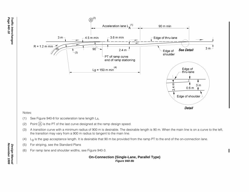
On-Connection (Single-Lane, Parallel Type)Figure 940-9b
Notes:
(1) See Figure 940-8 for acceleration lane length LA.
(2) Point A is the PT of the last curve designed at the ramp design speed.
(3) A transition curve with a minimum radius of 900␣ m is desirable. The desirable length is 90␣ m. When the main line is on a curve to the left,the transition may vary from a 900␣ m radius to tangent to the main line.
(4) Lg is the gap acceptance length. It is desirable that 90␣ m be provided from the ramp PT to the end of the on-connection lane.
(5) For striping, see the Standard Plans
(6) For ramp lane and shoulder widths, see Figure 940-3.
Traffic Interchanges
Design M
anualP
age 940-18N
ovember 1999

On-Connection (Two-Lane, Parallel Type)Figure 940-9c
Notes:
(1) See Figure 940-8 for acceleration lane length LA.
(2) Point A is the PT of the last curve designed at the ramp design speed.
(3) A transition curve with a minimum radius of 900␣ m is desirable. The desirable length is 90␣ m. When the main line is on a curve to the left,the transition may vary from a 900␣ m radius to tangent to the main line.
(4) Lg is the gap acceptance length. It is desirable that 90 m be provided from the ramp PT to the end of the on-connection lane.
(5) Added lane or 450␣ m auxiliary lane, plus 180␣ m taper.
(6) For striping, see the Standard Plans
(7) For ramp lane and shoulder widths, see Figure 940-3.
Design M
anualT
raffic InterchangesN
ovember 1999
Page 940-19

On-Connection (Two-Lane, Taper Type)Figure 940-9d
Notes:
(1) See Figure 940-8 for acceleration lane length LA.
(2) Point A is the PT of the last curve designed at the ramp design speed.
(3) A transition curve with a minimum radius of 900␣ m is desirable. The desirable length is 90␣ m. When the main line is on a curve to the left,the transition may vary from a 900␣ m radius to tangent to the main line.
(4) Added lane or 450␣ m auxiliary lane, plus 180␣ m taper.
(5) For striping, see the Standard Plans
(6) For ramp lane and shoulder widths, see Figure 940-3.
Traffic Interchanges
Design M
anualP
age 940-20N
ovember 1999

Off-Connection (Single-Lane, Taper Type)Figure 940-12a
Notes:
(1) See Figure 940-10 for deceleration lane length LD.
(2) Point A is the PC of the first curve designed at the ramp design speed.
(3) For striping, see the Standard Plans
(4) For ramp lane and shoulder widths, see Figure 940-3.
Design M
anualT
raffic InterchangesN
ovember 1999
Page 940-23

Off-Connection (Single Lane, Parallel Type)Figure 940-12b
Notes:
(1) See Figure 940-10 for deceleration lane length LD.
(2) Point A is the PC of the first curve designed at the ramp design speed.
(3) For striping, see the Standard Plans.
(4) For ramp lane and shoulder widths, see Figure 940-3.
Traffic Interchanges
Design M
anualP
age 940-24N
ovember 1999

Off-Connection (Single-Lane, One-Lane Reduction)Figure 940-12c
Notes:
(1) See Figure 940-10 for deceleration lane length LD.
(2) Point A is the PC of the first curve designed at the ramp design speed.
(3) Auxiliary lane between closely spaced interchanges to be dropped.
(4) For striping, see the Standard Plans.
(5) For ramp lane and shoulder widths, see Figure 940-3.
Design M
anualT
raffic InterchangesN
ovember 1999
Page 940-25

Off-Connection (Two-Lane, Taper Type)Figure 940-12d
Notes:
(1) See Figure 940-10 for deceleration lane length LD.
(2) Point A is the PC of the first curve designed at the ramp design speed.
(3) Lane to be dropped or auxiliary lane with a minimum length of 450␣ m with a 90␣ m taper.
(4) For striping, see the Standard Plans.
(5) For ramp lane and shoulder widths, see Figure 940-3.
Traffic Interchanges
Design M
anualP
age 940-26N
ovember 1999
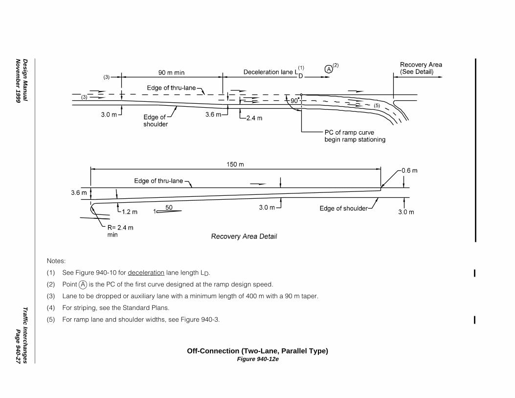
Off-Connection (Two-Lane, Parallel Type)Figure 940-12e
Notes:
(1) See Figure 940-10 for deceleration lane length LD.
(2) Point A is the PC of the first curve designed at the ramp design speed.
(3) Lane to be dropped or auxiliary lane with a minimum length of 400␣ m with a 90␣ m taper.
(4) For striping, see the Standard Plans.
(5) For ramp lane and shoulder widths, see Figure 940-3.
Design M
anualT
raffic InterchangesN
ovember 1999
Page 940-27

Collector Distributor (Off-Connections)Figure 940-13b
Notes:
(1) See Figure 940-10 for deceleration lane length LD.
(2) Point A is the PC of the first curve designed at the ramp design speed.
(3) For striping, see the Standard Plans.
Design M
anualT
raffic InterchangesN
ovember 1999
Page 940-29

Design Manual Auxiliary LanesNovember 1999 Page 1010-1
1010 Auxiliary Lanes
1010.01 General1010.02 References1010.03 Definitions1010.04 Climbing Lanes1010.05 Passing Lanes1010.06 Slow Moving Vehicle Turnouts1010.07 Shoulder Driving for Slow Vehicles1010.08 Emergency Escape Ramps1010.09 Chain-Up Areas1010.10 Documentation
1010.01 GeneralAuxiliary lanes are used to comply with capacityrequirements; to maintain lane balance; toaccommodate speedx change, weaving, andmaneuvering for entering and exiting traffic;or to encourage carpools, vanpools, and the useof transit.
See the Traffic Manual and the MUTCD forsigning of auxiliary lanes.
Although slow vehicle turnouts, shoulder drivingfor slow vehicles, and chain-up areas are notauxiliary lanes they are covered in this chapterbecause they perform a similar function.
See the following chapters for additionalinformation:
Chapter Subject
910 Turn lanes910 Speed change lanes at intersections940 Speed change lanes at interchanges940 Collector distributor roads940 Weaving lanes1050 High occupancy vehicle lanes
1010.02 ReferencesRevised Code of Washington (RCW) 46.61,Rules of the Road.
Manual on Uniform Traffic Control Devicesfor Streets and Highways (MUTCD), USDOT,FHWA; including the Washington State Modifi-cations to the MUTCD, M 24-01. WSDOT
Traffic Manual, M 51-02, WSDOT.
A Policy on Geometric Design of Highways andStreets (Green Book), AASHTO, 1994
Emergency Escape Ramps for Runaway HeavyVehicles, FHWA-T5-79-201, March 1978
Highway Capacity Manual (Special Report 209),Transportation Research Board
NCHRP Synthesis 178, Truck Escape Ramps,Transportation Research Board
1010.03 Definitionsauxiliary lane The portion of the roadwayadjoining the through lanes for parking, speedchange, turning, storage for turning, weaving,truck climbing, passing, and other purposessupplementary to through-traffic movement.
climbing lane An auxiliary lane used for thediversion of slow traffic from the through lane.
emergency escape rampA roadway leavingthe main roadway designed for the purpose ofslowing and stopping out-of-control vehiclesaway from the main traffic stream.
lane A strip of roadway used for a single lineof vehicles.
lateral clearance The distance from the edgeof traveled way to a roadside object.
posted speedThe maximum legal speed asposted on a section of highway using regulatorysigns.
passing lane An auxiliary lane on a two-lanehighway used to provide the desired frequencyof safe passing zones.
roadway The portion of a highway, includingshoulders, for vehicular use. A divided highwayhas two or more roadways.
shoulder The portion of the roadwaycontiguous with the traveled way, primarily foraccommodation of stopped vehicles, emergencyuse, lateral support of the traveled way, and useby pedestrians and bicycles.

Auxiliary Lanes Design ManualPage 1010-2 November 1999
slow moving vehicle turnouts A widenedshoulder area to provide room for a slow movingvehicle to pull safely out of the through traffic,allow vehicles following to pass, and return tothe through lane.
traveled way The portion of the roadwayintended for the movement of vehicles, exclusiveof shoulders and lanes for parking, turning, andstorage for turning.
1010.04 Climbing Lanes(1) GeneralNormally, climbing lanes are associated withtruck traffic, but they may also be considered inrecreational or other areas that are subject to slowmoving traffic. Climbing lanes are designedindependently for each direction of travel.
Generally, climbing lanes are provided when therequirements of two warrants - speed reductionand level of service - are exceeded. The require-ments of either warrant may be waived if, forexample, slow moving traffic is demonstrablycausing a high accident rate or congestion thatcould be corrected by the addition of a climbinglane. However, under most conditions climbinglanes are built when the requirements of bothwarrants are satisfied.
(2) Warrant No. 1 — Speed ReductionFigure 1010-2a shows how the percent and lengthof grade affect vehicle speeds. The data is basedon a typical heavy truck.
The maximum allowable entrance speed, asreflected on the graphs, is 55 mph. Note that thisis the maximum value to be used regardless of theposted speed of the highway. When the postedspeed is above 55 mph, use 55 mph in place ofthe posted speed. Examine the profile at least0.4 km preceding the grade to obtain a reasonableapproach speed.
If a vertical curve makes up part of the lengthof grade, approximate the equivalent uniformgrade length.
Whenever the gradient causes a 15 mph speedreduction below the posted speed limit for typicalheavy truck for either two-lane or multilanehighways, the speed reduction warrant is satisfied(see Figure 1010-2b for an example).
(3) Warrant No. 2 — Level of Service(LOS)The level of service warrant for two-lanehighways is fulfilled when the up-grade trafficvolume exceeds 200 VPH and the up-grade truckvolume exceeds 20 VPH. On multilane highways,use Figure 1010-3.
(4) DesignWhen a climbing lane is justified, design it inaccordance with Figure 1010-4. Provide signingand delineation to identify the presence of theauxiliary lane. Begin climbing lanes at the pointwhere the speed reduction warrant is met andend them where the warrant ends for multilaneand 90 m beyond for 2-lane highways. Considerextending the auxiliary lane over the crest toimprove vehicle acceleration and the sightdistance.
Design climbing lane width equal to that of theadjoining through lane and at the same crossslope as the adjoining lanes. When ever possible,maintain the shoulders at standard width for theclass of highway. However, on two-way two-lanehighways, the shoulder may be reduced to 1.2 mwith justification.
1010.05 Passing Lanes(1) GeneralPassing lanes are desirable where a sufficientnumber and length of safe passing zones donot exist and the speed reduction warrant fora climbing lane is not satisfied. Figure 1010-5may be used to determine if a passing lane isrecommended.
(2) DesignWhen a passing lane is justified, design it inaccordance with Figure 1010-6. Make the lanelong enough to permit several vehicles to pass.Passing lanes longer than 3 km can cause thedriver to lose the sense that the highway isbasically a two-lane facility.

Design Manual Auxiliary LanesNovember 1999 Page 1010-3
Passing lanes are preferably four-lane sections.
A three-lane section may be used, however.Alternate the direction of the passing lane atshort intervals to ensure passing opportunitiesfor both directions and to discourage illegalactions of frustrated drivers.
Make the passing lane width equal to theadjoining through lane and at the same crossslope. Full-width shoulders for the highwayclass are preferred; however, with justification,the shoulders may be reduced to 1.2 m. Provideadequate signing and delineation to identify thepresence of an auxiliary lane.
1010.06 Slow Moving VehicleTurnouts(1) GeneralOn a two-lane highway where passing is unsafe,a slow moving vehicle is required, by RCW46.61.427, to turn off the through lane wherever asafe turnout exists, in order to permit the follow-ing vehicles to proceed. A slow moving vehicleis one that is traveling at a speed less than thenormal flow of traffic, behind which five ormore vehicles are formed in a line.
A slow moving vehicle turnout is not an auxiliarylane. Its purpose is to provide sufficient roomfor a slow moving vehicle to safely pull out ofthrough traffic and stop if necessary, allowvehicles following to pass, then return to thethrough lane. Generally, a slow moving vehicleturnout is provided on existing roadways wherepassing opportunities are limited, where slowmoving vehicles such as trucks and recreationalvehicles are predominant, and where the cost toprovide a full auxiliary lane would be prohibitive.
(2) DesignBase the design of a slow moving vehicle turnoutprimarily on sound engineering judgment andFigure 1010-7. Design may vary from onelocation to another. A minimum length of 30 mprovides adequate storage, since additionalstorage is provided within the tapers and shoul-ders. The maximum length is 0.5 km includingtapers. Surface turnouts with a stable unyieldingmaterial such as BST or ACP with adequatestructural strength to support the heavier traffic.
Locate slow vehicle turnouts where at leastDesign Stopping Sight Distance (Chapter 650)is available, decision sight distance is preferred,so that vehicles can safely reenter the throughtraffic. Sign slow moving vehicle turnouts toidentify their presence.
When a slow moving vehicle turnout is to bebuilt, document the location and why it wasselected.
1010.07 Shoulder Driving for SlowVehicles(1) GeneralFor projects where climbing or passing lanesare justified, but are not within the scope of theproject, or where meeting the warrants for theselanes are borderline, the use of a shoulder drivingsection is an alternative.
Review the following when considering ashoulder driving section:
• Horizontal and vertical alignment
• Character of traffic
• Presence of bicycles
• Clear zone (Chapter 700)
(2) DesignWhen designing a shoulder for shoulder driving,use a minimum length of 180 m. The minimumshoulder width is 2.4 m with 3.0 m preferred.When barrier is present, the minimum width is3.0 m with 3.6 m preferred. Adequate structuralstrength for the anticipated traffic is necessaryand may require reconstruction. Select locationswhere the side slope meets the requirements ofChapter 640 for new construction and Chapter430 for existing roadways. When a transition isrequired at the end of a shoulder driving section,use a 50:1 taper.
Signing for shoulder driving is required. Installguideposts when shoulder driving is to bepermitted at night.
Document the need for shoulder driving and whya lane is not being built.

Auxiliary Lanes Design ManualPage 1010-4 November 1999
1010.08 Emergency EscapeRamps(1) GeneralConsider an emergency escape ramp wheneverlong steep down grades are encountered. In thissituation the possibility exists of a truck losing itsbrakes and going out of control at a high speed.Consult local maintenance personnel and checktraffic accident records to determine if an escaperamp is justified.
(2) Design(a) Type. Escape ramps are one of thefollowing types:
• Gravity escape ramps are ascending graderamps paralleling the traveled way. They arecommonly built on old roadways. Their longlength and steep grade can present the driverwith control problems, not only in stopping,but with rollback after stopping. Gravityescape ramps are the least desirable design.
• Sand pile escape ramps are piles of loose,dry sand dumped at the ramp site, usually notmore than 120 m in length. The decelerationis usually high and the sand can be affectedby weather conditions; therefore, they are lessdesirable than arrester beds. However, wherespace is limited they may be suitable.
• Arrester beds are parallel ramps filled witha smooth, coarse, free-draining gravel. Theystop the out-of-control vehicle by increasingthe rolling resistance. Arrester beds arecommonly built on an up grade to add thebenefits of gravity to the rolling resistance.However, successful arrester beds have beenbuilt on a level or descending grade.
(b) Location. The location of an escape rampwill vary depending on terrain, length of grade,and roadway geometrics. The best locationsinclude in advance of a critical curve, near thebottom of grade, or before a stop. It is desirablethat the ramp leave the roadway on a tangent atleast 5 km from the beginning of the down-grade.
(c) Length. Lengths will vary dependingon speed, grade, and type of design used. Theminimum length is 60 m. Calculate the stoppinglength using the following equation:
L =
Where:L = stopping distance (m)V = entering speed (mph)R = rolling resistance (see Figure 1010-1)G = grade of the escape ramp (%)
Speeds of out-of control trucks rarely exceed90 mph; therefore, an entering speed of 90 mphis preferred. Other entry speeds may be usedwhen justification and the method used todetermine the speed is documented.
Material R
Roadway 1
Loose crushed aggregate 5
Loose noncrushed gravel 10
Sand 15
Pea gravel 25
Rolling Resistance (R)Figure 1010-1
(d) Width. The width of each escape ramp willvary depending on the needs of the individualsituation. It is desirable for the ramp to be wideenough to accommodate more than one vehicle.The desirable width of an escape ramp to accom-modate two out-of-control vehicles is 12 m andthe minimum width is 8 m.
(e) The following items are additional consider-ations in the design of emergency escape ramps:
• If possible, at or near the summit, providea pull-off brake-check area. Also, includeinformative signing about the upcomingescape ramp in this area.
• A free draining, smooth, noncrushed gravelis preferred for an arrester bed. To assist insmooth deceleration of the vehicle, taper thedepth of the bed from 75 mm at the entry toa full depth of 600 to 750 mm in not lessthan 30 m.
• Mark and sign in advance of the ramp.Discourage normal traffic from using orparking in the ramp. Sign escape ramps inaccordance with the guidance contained inthe MUTCD for runaway truck ramps.
V2
0.98(R±G)
Design Manual Auxiliary LanesNovember 1999 Page 1010-5
• Provide drainage adequate to prevent the bedfrom freezing or compacting.
• Consider including an impact attenuator atthe end of the ramp if space is limited.
• A surfaced service road adjacent to thearrester bed is needed for wreckers andmaintenance vehicles to remove vehiclesand make repairs to the arrester bed.Anchors are desirable at 90 m intervals tosecure the wrecker when removing vehiclesfrom the bed.
A typical example of an arrester bed is shown inFigure 1010-8.
Include justification, all calculations, and anyother design considerations in the documentationof an emergency escape ramp documentation.
1010.09 Chain-Up AreaProvide chain-up areas to allow chains to be puton vehicles out of the through lanes at locationswhere traffic enters chain enforcement areas.Provide chain-off areas to remove chains outof the through lanes for traffic leaving chainenforcement areas.
Chain-up or chain-off areas are widened shoul-ders, designed as shown in Figure 1010-9. Locatechain-up and chain-off areas where the grade is6% or less and preferably on a tangent section.
Consider illumination for chain-up and chain-offareas on multilane highways. When decidingwhether or not to install illumination, considertraffic volumes during the hours of darkness andthe availability of power.
1010.10 DocumentationThe following documents are to be preserved inthe project file. See Chapter 330.
o Documentation that climbing lane warrant1 has been met
o Documentation that climbing lane warrant2 has been met
o Justification for waiving climbing lanewarrant 1 or 2
o Justification for passing lanes
o Slow moving vehicle turnoutdocumentation
o Emergency escape ramp documentation
P65:DP/DMM
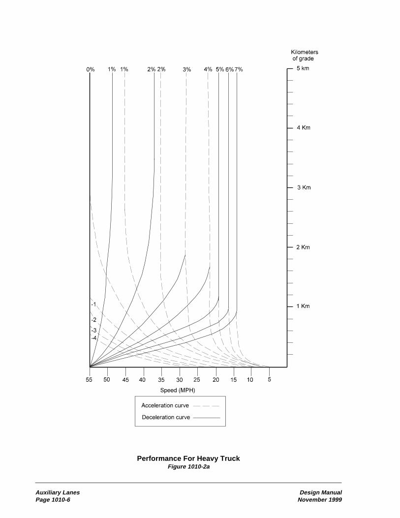
Auxiliary Lanes Design ManualPage 1010-6 November 1999
Performance For Heavy TruckFigure 1010-2a

Design Manual Auxiliary LanesNovember 1999 Page 1010-7
Given: A 2-lane highway meeting the level of service warrant, with the above profile, and a 55 mphposted speed.
Determine: Is the climbing lane warranted and, if so, how long?
Solution:
1. Follow the 4% grade deceleration curve from a speed of 55 mph to a speed of 40 mph at 500 m. Thespeed reduction warrant is met and a climbing lane is needed.
2. Continue on the 4% grade deceleration curve to 1200 m. Note that the speed at the end of the 4%grade is 25 mph.
3. Follow the 1% grade acceleration curve from a speed of 25 mph for 300 m. Note that the speed at theend of the 1% grade is 34 mph.
4. Follow the -2% grade acceleration curve from a speed of 34 mph to a speed of 40 mph, ending thespeed reduction warrant. Note the distance required is 100 m.
5. The total auxiliary lane length is (1200-500)+300+100+90=1190 m. 90 m is added to the speedreduction warrant for a 2-lane highway, see the text and Figure 1010-4.
Speed Reduction ExampleFigure 1010-2b
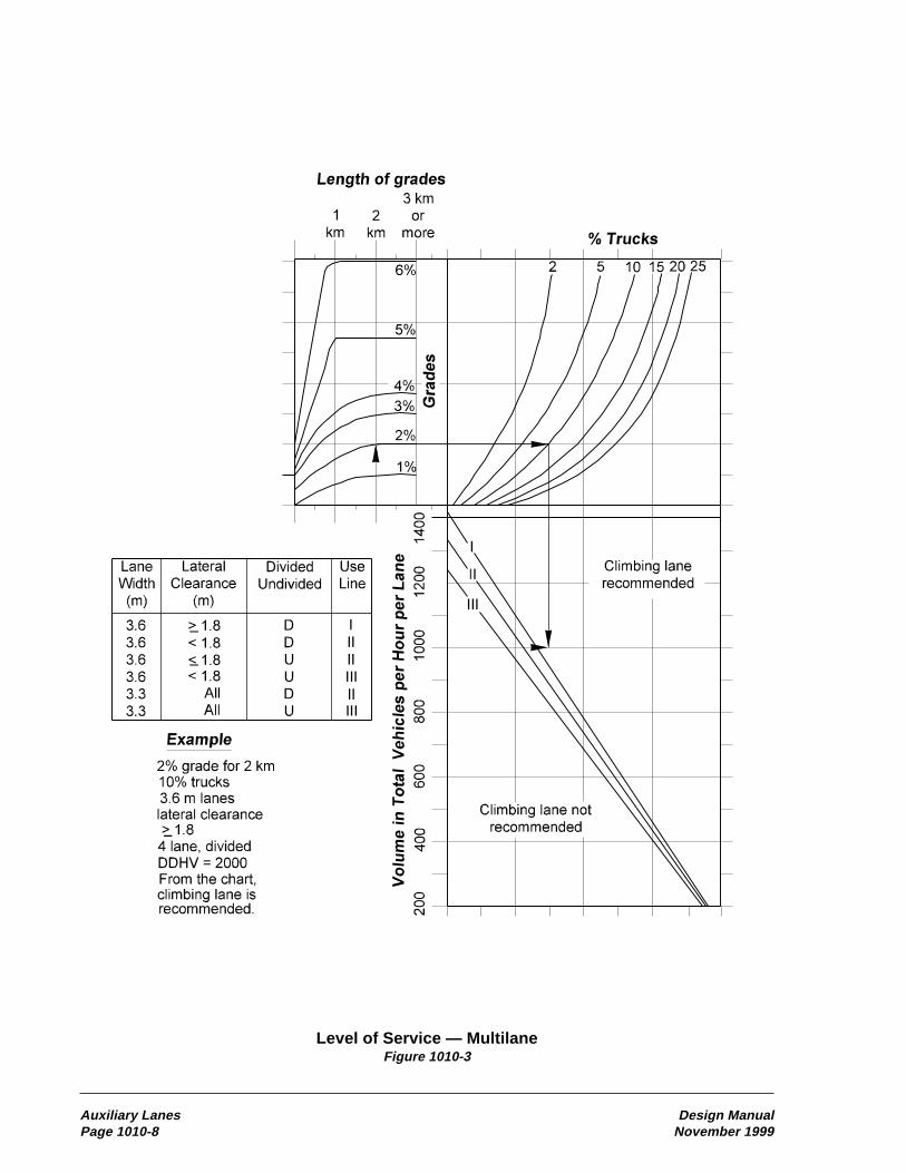
Auxiliary Lanes Design ManualPage 1010-8 November 1999
Level of Service — MultilaneFigure 1010-3

Design Manual Auxiliary LanesNovember 1999 Page 1010-9
Auxiliary Climbing LaneFigure 1010-4

Auxiliary Lanes Design ManualPage 1010-10 November 1999
Warrant For Passing LanesFigure 1010-5
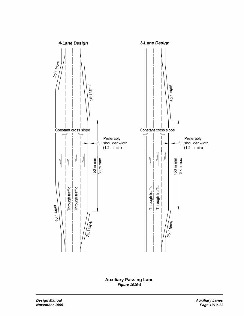
Design Manual Auxiliary LanesNovember 1999 Page 1010-11
Auxiliary Passing LaneFigure 1010-6

Auxiliary Lanes Design ManualPage 1010-12 November 1999
Slow Moving Vehicle TurnoutFigure 1010-7
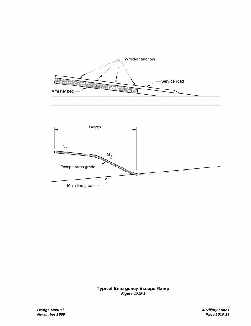
Design Manual Auxiliary LanesNovember 1999 Page 1010-13
Typical Emergency Escape RampFigure 1010-8
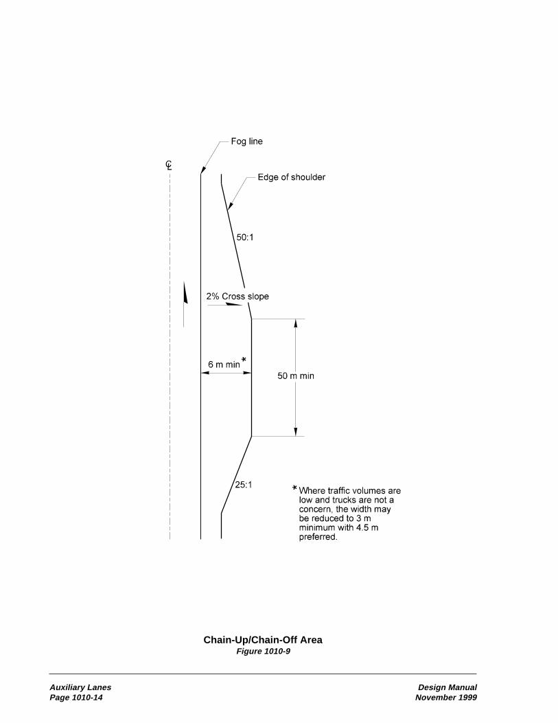
Auxiliary Lanes Design ManualPage 1010-14 November 1999
Chain-Up/Chain-Off AreaFigure 1010-9

Typical Truck StorageFigure 1030-1
Design Manual Safety Rest Areas and Traveler ServicesNovember 1999 Page 1030-3

Typical Single RV Dump Station LayoutFigure 1030-2
Safety Rest Areas and Traveler Services Design ManualPage 1030-4 November 1999

Typical Two RV Dump Station LayoutFigure 1030-3
Design Manual Safety Rest Areas and Traveler ServicesNovember 1999 Page 1030-5

(c) Section
• Show cross sections of the waterway.The extent will be determined by the OSCHydraulics Branch.
The requirements for waterway profile and crosssections may be less stringent if the HydraulicsBranch has sufficient documentation (FEMAreports, for example) to make a determination.Contact the Hydraulics Branch to verify theextent of the information needed. Coordinateany rechannelization of the waterway with theHydraulics Branch.
Many waterway crossings require a permit fromthe U.S. Coast Guard. (See Chapter 240.)Generally, ocean tide influenced waterwaysand waterways used for commercial navigationrequire a Coast Guard permit. These structuresrequire the following additional information:
• Names and addresses of the landownersadjacent to the bridge site.
• Quantity of new embankment material withinthe floodway. This quantity denotes, in cubicmeters, the material below normal high waterand the material above normal high water.
Some waterways may qualify for an exemptionfrom Coast Guard permit requirements if certainconditions are met. See the Bridge DesignManual. If the waterway crossing appears tosatisfy these conditions, then submit a statementexplaining why this project is exempt from aCoast Guard permit. Attach this exemptionstatement to the Environmental ClassificationSummary prepared for the project and submit itto the OSC Project Development Branch forprocessing to FHWA.
The region is responsible for coordination withthe Bridge and Structures Office, U. S. ArmyCorps of Engineers, and U. S. Coast Guard forwaterways that may qualify for a permit exemp-tion. The Bridge and Structures Office isresponsible for coordination with the U.S. CoastGuard for waterways that require a permit.
1110.05 Additional Data for GradeSeparations(1) Highway-Railroad SeparationSupplement bridge site data for structuresinvolving railroads with the following:
(a) Plan
• Alignment of all existing and proposedrailroad tracks.
• Center-to-center spacing of all tracks.
• Angle, station, and coordinates of all inter-sections between the highway alignment andeach track.
• Location of railroad right of way lines.
• Horizontal curve data. Include coordinatesfor all circular and spiral curve control points.
(b) Profile
• For proposed railroad tracks; profile, verticalcurve, and superelevation data for each track.
• For existing railroad tracks, elevationsaccurate to 3 mm taken at intervals of 2.5 to3 m along the top of the highest rail of eachtrack. Provide elevations to 15 m beyondthe extreme outside limits of the existingor proposed structure. Tabulate elevationsin a format acceptable to the Bridge andStructures Office.
(2) Highway-Highway SeparationSupplement bridge site data for structuresinvolving other highways by the following:
(a) Plan
• Alignment of all existing and proposedhighways, streets, and roads.
• Angle, station, and coordinates of all inter-sections between all crossing alignments.
• Horizontal curve data. Include coordinatesfor all curve control points.
(b) Profile
• For proposed highways; profile, verticalcurve, and superelevation data for each.
Design Manual Site Data for StructuresNovember 1999 Page 1110-3
• For existing highways; elevations accurate to3 mm taken at intervals of 2.5 to 3 m alongthe center line or crown line and each edgeof shoulder, for each alignment, to definethe existing roadway cross slopes. Provideelevations to 15 m beyond the extremeoutside limits of the existing or proposedstructure. Tabulate elevations in a formatacceptable to the Bridge and StructuresOffice format.
(c) Section
• Roadway sections of each undercrossingroadway indicating the lane and shoulderwidths, cross slopes and side slopes, ditchdimensions, and traffic barrier requirements.
• Falsework or construction opening require-ments. Specify minimum vertical clearances,lane widths, and shy distances.
1110.06 Additional Data forWideningsBridge rehabilitations and modifications thatrequire new substructure are defined as bridgewidenings.
Supplement bridge site data for structuresinvolving bridge widenings by the following:
• Submit DOT Form 235-002A, “SupplementalBridge Site Data-Rehabilitation/Modification.”
(a) Plan
• Stations for existing back of pavement seats,expansion joints, and pier center lines basedon field measurement along the survey lineand each curb line.
• Locations of existing bridge drains. Indicatewhether these drains are to remain in use orbe plugged.
(b) Profile
• Elevations accurate to 3 mm taken at inter-vals of 2.5 to 3 m along the curb line of theside of the structure being widened. Pairthese elevations with corresponding eleva-tions (same station) taken along the crownline or an offset distance (minimum of 3 mfrom the curb line). This information willbe used to establish the cross slope of theexisting bridge. Tabulate elevations in aformat acceptable to the Bridge andStructures Office.
Take these elevations at the level of the concreteroadway deck. For bridges with latex modified ormicrosilica modified concrete overlay, elevationsat the top of the overlay will be sufficient. Forbridges with a nonstructural overlay, such as anasphalt concrete overlay, take elevations at thelevel of the concrete roadway deck. For skewedbridges, take elevations along the crown line or atan offset distance (3 m minimum from the curbline) on the approach roadway for a sufficientdistance to enable a cross slope to be establishedfor the skewed corners of the bridge.
1110.07 DocumentationThe following documents are to be preserved inthe project file. See Chapter 330.
o DOT Form 235-002, “Bridge Site Data -General”
o DOT Form 235-001, Bridge Site Data forStream Crossings”
o DOT Form 235-002A, “SupplementalBridge Site Data - Rehabilitation/Modification”
o United States Coast Guard permit
o Environmental Classification Summary
P65:DP/DM11
Site Data for Structures Design ManualPage 1110-4 November 1999

Review Chapter 1110 of the Design Manualfor further information and description of the items listed below.
PLAN (In CAD file.)_____ Survey Lines and Station Ticks_____ Survey Line Intersection Angles_____ Survey Line Intersection Stations_____ Survey Line Bearings_____ Roadway and Median Widths_____ Lane and Shoulder Widths_____ Sidewalk Width_____ Connection/Widening for Traffic Barrier_____ Profile Grade and Pivot Point_____ Roadway Superelevation Rate
(if constant)_____ Lane Taper and Channelization Data_____ Traffic Arrows_____ Mileage to Towns Along Main Line_____ Existing Drainage Structures_____ Existing Utilities — Type/Size/Location_____ New Utilities — Type/Size/Location_____ Light standards, Junction boxes,
Conduits_____ Bridge Mounted Signs and Supports_____ Contours_____ Bottom of Ditches_____ Test Holes (if available)_____ Riprap Limits_____ Stream Flow Arrow_____ R/W Lines and/or Easement Lines_____ Exist. Bridge No. (to be removed,
widened)_____ Section, Township, Range_____ City or Town_____ North Arrow_____ SR Number_____ Scale
TABLES (In tabular format in CAD file.)_____ Curb Line Elevations. at Top of Exist.
Br. Deck_____ Undercrossing Roadway Existing
Elevations_____ Undercrossing Railroad Existing
Elevations_____ Curve Data
OTHER SITE DATA (May be in CAD or may beon supplemental sheets or drawings.)_____ Superelevation Diagrams_____ End Slope Rate
_____ Profile Grade Vertical Curves_____ Coast Guard Permit Status_____ Railroad Agreement Status_____ Highway Classification_____ Design Speed_____ ADT, DHV, and % T
FORMS (Information noted on the form orattached on supplemental sheets or drawings.)
Bridge Site Data General_____ Slope Protection_____ Pedestrian Barrier/Pedestrian Rail
Height Requirements_____ Construction/Falsework Openings_____ Stage Construction Channelization Plans_____ Bridge (before/with/after) Approach Fills_____ Datum_____ Video of Site_____ Photographs of Site_____ Control Section_____ Project Number_____ Region Number_____ Highway Section
Bridge Site Data for Stream Crossings_____ Water Surface Elevations and Flow Data_____ Riprap Cross Section Detail
Supplemental Bridge SiteData-Rehabilitation/Modification
BRIDGE, CROSSROAD, AND APPROACHROADWAY CROSS SECTIONS(May be in CAD or separate drawings.)_____ Bridge Roadway Width_____ Lane and Shoulder Widths_____ Profile Grade and Pivot Point_____ Superelevation Rate_____ Survey Line_____ PB/Pedestrian Rail Dimensions_____ Stage Construction Lane Orientations_____ Locations of Temporary Barrier_____ Conduits/Utilities in Bridge_____ Location and Depth of Ditches_____ Shoulder Widening for Barrier_____ Side Slope Rate
Bridge Site Data Check ListFigure 1110-1
Design Manual Site Data for StructuresNovember 1999 Page 1110-5
1130 Retaining Walls and Steep Reinforced Slopes
• Traffic characteristics
• Constructibility
• Impact to any adjacent environmentallysensitive areas
• Impact to adjacent structures
• Potential added lanes
• Length and height of wall
• Material to be retained
• Foundation support and potential fordifferential settlement
• Ground water
• Earthquake loads
• Right of way costs
• Need for construction easements
• Risk
• Overall cost
• Visual appearance
If the wall or toe of a reinforced slope is to belocated adjacent to the right of way line, considerthe space needed in front of the wall/slope toconstruct it.
(1) Retaining Wall ClassificationsRetaining walls are generally classified asgravity, semigravity, nongravity cantilever, oranchored. Examples of the various types of wallsare provided in Figures 1130-1a through 1c.
Gravity walls derive their capacity to resistlateral soil loads through a combination of deadweight and sliding resistance. Gravity wallscan be further subdivided into rigid gravitywalls, prefabricated modular gravity walls,and Mechanically Stabilized Earth (MSE)gravity walls.
Rigid gravity walls consist of a solid mass ofconcrete or mortared rubble and use the weightof the wall itself to resist lateral loads.
1130.01 References1130.02 General1130.03 Design Principles1130.04 Design Requirements1130.05 Guidelines for Wall/Slope Selection1130.06 Design Responsibility and Process1130.07 Documentation
113.01 ReferencesBridge Design Manual, M 23-50, WSDOT
Standard Plans for Road, Bridge, and MunicipalConstruction (Standard Plans), M 21-01,WSDOT
Plans Preparation Manual, M 22-31, WSDOT
Roadside Manual, M 25-39, WSDOT
1130.02 GeneralThe function of a retaining wall is to form anearly vertical face through confinement and/orstrengthening of a mass of earth or other bulkmaterial. Likewise, the function of a reinforcedslope is to strengthen the mass of earth or otherbulk material such that a steep (up to 2V:1H)slope can be formed. In both cases, the purpose ofconstructing such structures is to make maximumuse of limited right of way. The differencebetween the two is that a wall uses a structuralfacing whereas a steep reinforced slope does notrequire a structural facing. Reinforced slopestypically use a permanent erosion control mattingwith low vegetation as a slope cover to preventerosion. See the Roadside Manual for moreinformation.
To lay out and design a retaining wall orreinforced slope, consider the following items:
• Functional classification
• Highway geometry
• Design Clear Zone requirements(Chapter 700)
• The amount of excavation required
Design Manual Retaining Walls and Steep Reinforced SlopesNovember 1999 Page 1130-1

Once the detailed wall plans and designs areavailable as shop drawings after contract award,the Bridge and Structures Office will review andapprove the wall shop drawings and calculations,with the exception of geosynthetic walls whichare reviewed and approved by the GeotechnicalServices Branch.
(c) Nonpreapproved Proprietary Walls. Finaldesign approval authority for nonpreapprovedproprietary walls is the same as for preapprovedproprietary walls. The region initiates the designeffort for all nonpreapproved wall systems bysubmitting wall plan, profile, cross-section, andother information for the proposed wall to theBridge and Structures Office, with copies to theGeotechnical Services Branch and the PrincipalArchitect. The Bridge and Structures Officecoordinates the wall design effort.
Once the geotechnical and architectural assess-ments have been completed and the desired walltypes selected, the Bridge and Structures Officecontacts suppliers of the nonpreapproved wallsystems selected to obtain and review detailedwall designs and plans to be included in thecontract PS&E.
To ensure fair competition between all wallalternatives included in the PS&E, the wall facequantities for those wall systems subject to thesame face embedment requirements shouldbe identical.
The Bridge and Structures Office develops thespecial provisions and cost estimates for thenonpreapproved proprietary walls and sendsthe wall PS&E to the region for inclusion inthe final PS&E in accordance with the PlansPreparation Manual.
(d) Nonstandard Nonproprietary Walls.With the exception of rockeries over 1.5 m high,nonproprietary geosynthetic walls and reinforcedslopes, and soil nail walls, the Bridge and Struc-tures Office coordinates with the GeotechnicalServices Branch and the Principal Architect tocarry out the design of all nonstandard, non-proprietary walls. In this case, the Bridge andStructures Office develops the wall preliminaryplan from site data provided by the region,
completes the wall design, and develops thenonstandard nonproprietary wall PS&E packagefor inclusion in the contract.
For rockeries over 1.5 m high, nonproprietarygeosynthetic walls and reinforced slopes, andsoil nail walls, the region develops wall/slopeprofiles, plans, and cross-sections and submitsthem to the Geotechnical Services Branch tocomplete a detailed wall/slope design.
For geosynthetic walls and slopes, and forrockeries, the region provides overall coordina-tion of the wall/slope design effort, includingcoordination with the Principal Architect regard-ing aesthetics and finishes, and the Region orOSC Landscape Architect if the wall uses vege-tation on the face. The Geotechnical ServicesBranch has overall design approval authority.Once the wall design has been completed, theGeotechnical Services Branch, and in somecases the Bridge and Structures Office, providesgeotechnical and structural plan details to beincluded in the region plan sheets and specialprovisions for the PS&E. The regionthen completes the PS&E package.
For soil nail walls, once the GeotechnicalServices Branch has performed the geotechnicaldesign, the Bridge and Structures Office, incooperation with the Geotechnical ServicesBranch, coordinates the design effort andcompletes the PS&E package.
(3) Guidelines for Wall/Slope DataSubmission for Design(a) Standard Walls, Proprietary Walls,Geosynthetic Walls/Slopes, and Soil NailWalls. Where OSC involvement in retainingwall/slope design is required (as for standardwalls and preapproved proprietary walls over 3 min height, gabions over 2 m in height, rockeriesover 1.5 m in height, all nonpreapproved propri-etary walls, geosynthetic walls/slopes, and allsoil nail walls), the region submits the followinginformation to the Geotechnical Services Branchor Bridge and Structures Office as appropriate:
• Wall/slope plans.
• Profiles showing the existing and final gradesin front of and behind the wall.
Retaining Walls and Steep Reinforced Slopes Design ManualPage 1130-12 November 1999

Design Manual IndexNovember 1999 Page 1
Index
Application for permit to remove or destroy asurvey monument, 1450-5
Approaches:commercial, 920-3full access control, 1420-1noncommercial, 920-3partial access control, 1420-2railroad, 1420-6, 1420-7right of way considerations, 1410-1road, 920-1, 1410-1, 1420-8
Approach rails to bridges, 710-13Approval:
access report, 1430-1environmental, 220-8, 220-10governmental agencies, 240-1hearing plans, 1430-2interchange plans, 940-10materials source, 510-1, 510-16
Archaeological sites, 220-5Army Corps of Engineers (COE), 240-1Arterial HOV, 1050-10Arterial HOV, definition, 1050-1Arterial programs, 120-1Asphalt concrete pavement, 520-3, 520-4Attenuators, impact, 720-1Authorized road approach, 920-1Auxiliary lane, 1010-1
added to basic, 620-4chain-up area, 1010-5climbing lanes, 1010-2emergency escape ramps, 1010-4interchanges, 940-6left turn, 910-4passing lanes, 1010-2railroad grade crossings, 930-2right turn, 910-6shoulder driving for slow vehicles,
1010-3slow moving vehicle turnouts, 1010-3speed change lanes, 910-6two-way left turn, 910-5
Average weekday vehicle trip ends, 920-1
AAbbreviations, 110-1Acceleration lane, 910-6, 910-29, 940-6, 940-16Access:
approach criteria, 1420-3, 1420-5commercial approaches, 1420-5, 1420-6control development, 1430-1crossroads at interchange ramps, 1420-1design policy, 1420-1frontage roads, 1420-7full control, 1420-1general requirements, 1430-1hearing, 210-12, 1430-2hearing plan, 1430-2illumination, 840-1location of utilities, 1410-4, 1420-2,
1420-4, 1420-5, 1420-7modified control, 1420-4partial control, 1420-2pedestrian facilities, 1020-8programming for funds, 1410-4public transportation facilities, 1060-1railroad approaches, 1420-6report, 1430-1report plan, 1430-1road approaches, 1410-1
Access Point Decision Report, 1425-1access point decision report and
supporting analyses, 1425-1report and supporting analysis, 1425-4
Administrative appeal hearing, 210-15Aesthetics for retaining walls, 1130-4Aesthetic/visual elements, 330-2, 330-4, 330-6Agreements, 240-10, 1420-7Air space, 1420-7Airport system plan, 120-3Airport-highway clearance, 240-13, 630-3Alignment:
horizontal, 620-1vertical, 630-1
Alignment monuments, 1450-2

Index Design ManualPage 2 November 1999
BBarrier delineation, 830-4Barriers, traffic, 710-1
beam guardrail, 710-4bridge rails, 710-13cable barrier, 710-10concrete barrier, 710-10design, 710-3dragnet, 710-14flare rate, 710-4length of need, 710-4, 710-16, 710-17longitudinal barrier deflection, 710-3other barriers, 710-14project requirements, 710-1redirectional land forms, 710-13shy distance, 710-3water filled barrier, 710-14
Base and surfacing typical section, 520-6Basic design level, 410-1
minor safety and minor preservationwork, 410-1
required safety items of work, 410-1Beam guardrail (see Guardrail)Bicycle facilities, 1020-1, 1060-4, 1120-4Borrow sites: see sundry sitesBoundaries, international, 1410-2Bridges, 1120-1
approach slab, 1120-3end slopes, 640-9geotechnical investigation, 510-11horizontal clearance, 1120-2location, 1120-1medians, 1120-2pedestrian and bicycle facilities, 1120-3permits, 240-1protective screening for highway
structures, 1120-3rail end treatment, 1120-3rails, 710-13site design, 1120-1slope protection, 1120-3structural capacity, 1120-1vertical clearance, 1120-2width for structures, 1120-2
Bridge rails, 710-13concrete safety shapes, 710-11end treatment, 1120-3thrie beam retrofit, 710-14, 710-21type 7 upgrade criteria, 710-2
Bridge site data, 1110-1checklist, 1110-5
Bridge width for structures, 1120-2Buffer-separated HOV facility, definition, 1050-1Bus berth design, 1060-14Bus stop pullouts, arterial streets, 1060-19Bus stops and pullouts, 1060-7
bus pullouts, 1060-9designation and location, 1060-7farside bus stops, 1060-8introduction, 1060-7mid-block bus stops, 1060-9near side bus stops, 1060-8placement, 1060-8turnout transfer center, 1060-16
CCable barrier, 710-10Cantilever sign supports, 820-3Capacity, highway, 610-1Categorical Exclusion (CE), Programmatical -
Class II - NEPA, 220-9Categorical Exclusion (CE), Documental -
Class II - NEPA, 220-9Categorical Exemption (CE), Class II - SEPA,
220-10Cattle passes, 1410-1Chain-off areas, 1010-5Chain-up areas, 1010-5Channel changes, 1210-2Channelization, 910-4
curbing, 910-6island, 910-7left-turn lanes, 910-4median, 910-22, 910-23right-turn lanes, 910-6speed change lanes, 910-6widening, 910-21
City street connections, 1420-7Classification:
cross section design data, 640-1functional, 120-4, 440-1geometric design data, 440-2project, 220-2state highway route systems, 120-4terrain, 440-1
Clearance:airport-highway, 240-4, 630-3bridge, 1120-1

Design Manual IndexNovember 1999 Page 3
Clear zone, 330-3, 700-1distance tables, 700-12ditch sections, 700-12values, 700-2
Climbing lanes, 1010-2level of service, 1010-2speed reduction, 1010-2
Closed circuit television cameras, 860-1Cloverleaf interchange, 940-2Coast Guard permits, 240-3Collector distributor roads, 940-8Collector system, 440-1Combined hearings, 210-15Commercial approaches, 920-3Commitment file, 220-1, 220-12Concrete barrier, 710-10
shapes, 710-11terminals, 710-12
Concurrent flow lane, definition, 1050-1Concurrent flow lanes, typical, 1050-11, 1050-24Conflict, 910-1Conforming road approach, 920-1Connections:
county road and city street, 1420-7interchange, 940-6
Contract preparation, 850-10Contraflow lane, definition, 1050-1Control monuments, 1450-2Construction identification signs, 820-1Construction Work Zone Traffic Control
Strategy, 810-1Construction Zone Guard Rail Energy Absorption
Terminal (GREATcz), 720-2, 720-9Consultants, geotechnical, 510-14Contour grading, 1310-1
general, 1310-1procedures, 1310-1recommendations, 1310-1references, 1310-1
Coordination:public agencies, 240-1
Corridor hearing, 210-11Corner radii, 910-2County road connections, 1420-7Critical slope, 700-1Crossings:
bicycle facilities, 1020-3pedestrian, 1020-3railroad grade, 930-1
ramp intersections, 940-6waterway, 1110-2
Crossroad, 910-1, 910-2Cross sections:
encroachment (RR), 930-3geometric, 640-1interchanges, 940-3roadway, 640-2
Cross slope, 430-2, 640-2, 640-4Crosswalks, 1020-9Cul-de-sac, 1420-7Curb cut ramps, 1020-9Curbing, 910-6Curves:
horizontal, 620-2superelevation, 640-4vertical, 630-2
DData for all structures, 1110-1Data for grade separations structures, 1110-3Data for waterway crossings structures, 1110-2Data for widening of structures, 1110-4Datums for surveying, 1440-2Deceleration lane, 910-6, 910-28, 940-7, 940-21Deep-seated instability, 1350-2Delineation, 830-1
barrier delineation, 830-4guideposts, 830-3pavement marking, 830-1procedure, 830-4raised pavement markers, 830-2spacing of wildlife reflectors, 830-5wildlife warning reflectors, 830-4
Department of Ecology, 240-6Depts. of Fisheries and Game, 240-6Department of Natural Resources, 240-8Design:
guides for highway capacity, 610-1hearing, 210-12items, 160-1manual description, 100-1manual revisions, 100-1principles, 160-1speed, 440-3, 940-4speed ramp, 940-4standards, 160-1, 430-3traffic barriers, 710-3vehicle, 430-3, 910-3vehicle turning movements, 1060-23

Index Design ManualPage 4 November 1999
Design approach for geosynthetics, 530-3ditch lining, 530-6permanent erosion control, moderate and
high survivability, 530-5separation, 530-4site-specific designs (all applications),
530-10soil stabilization, 530-5standard specification geotextile
application identification in theplans, 530-9
temporary silt fence, 530-6underground drainage, low and moderate
survivability, 530-3Design approval level, 330-6Design clear zone for ditch sections, 700-1Design components of signs, 820-2
cantilever sign structures, 820-3foundations, 820-3lateral clearance, 820-2location, 820-2longitudinal placement, 820-2sign heights, 820-2sign posts, 820-3truss-type sign bridges, 820-3
Design considerations of intersections at grade,910-2
crossroads, 910-2intersection configurations, 910-2traffic analysis, 910-2
Design criteria of HOV facilities, 1050-7adding an HOV lane, 1050-7barrier-separated HOV facilities, 1050-7concurrent flow HOV lanes, 1050-7design considerations, 1050-7design procedures, 1050-7direct access connections, 1050-8enforcement areas, 1050-9lane termination, 1050-8ramp bypass, 1050-8signs and pavement markings, 1050-9
Design documentation, 330-3design documents, 330-3design variance inventory, 330-4FHWA requirements, 330-3
Design documentation, approval, and processreview, 330-1
design approval, 330-4design documentation, 330-3
process review for region approvedprojects, 330-4
project definition phase, 330-2project development, 330-2purpose, 330-1
Design exception, 325-5Design hearing, 210-12Design Matrix 1, Interstate Routes (Main Line),
325-11Design Matrix 2, Interstate Interchange Areas,
325-12Design Matrix 3, NHS Routes (Main Line),
325-13Design Matrix 4, Non-Interstate Interchange
Areas, 325-14Design Matrix 4, Non-NHS Routes, 325-15Design matrix procedures, 325-1
design elements, 720-2design matrix procedures, 325-3design matrix selection guide, 325-4project type, 325-4, 325-2selecting a design matrix, 325-3terminology, 325-1using a design matrix, 325-4
Design of noise barriers, 1140-1Design of pavement structure, 520-1
asphalt concrete pavement and asphaltdistribution tables, 520-3, 520-4
base and surfacing typical section, 520-6to 520-14
estimating bituminous surface treatment,520-5
estimating tables, 520-1introduction, 520-1
Design recommendations for roadsidedevelopment, 1300-3
Design responsibility and process for retainingwalls, 1130-8
guidelines for wall/slope data submissionfor design, 1130-12
nonpreapproved proprietary walls,1130-12
nonstandard nonproprietary walls,1130-12
preapproved proprietary walls, 1130-10responsibility and process for design,
1130-8standard walls, 1130-10

Design Manual IndexNovember 1999 Page 5
Design requirements of retaining walls and steepreinforced slopes, 1130-2
aesthetics, 1130-4constructibility, 1130-4coordination with other design elements,
1130-4drainage design, 1130-3geotechnical and structural design,
1130-3investigation of soils, 1130-3wall/slope geometry, 1130-2
Design requirements for roadside development,1300-2
Design reviews and appovals, 330-8Design vehicle for intersection at grade, 910-3Designation of highway routes, 120-4Deviation, 325-5Diamond interchange, 940-3Direct access, HOV Direct Access Design
Guide, Draft, M 22-98Direct access ramp, definition, 1050-1Directional interchange, 940-3Disabled accessibility, transit, 1060-12
accessibility of bus stops and shelters,1060-13
introduction, 1060-12park and ride lots, 1060-12
Discipline report, 220-1Distributor facilities, 620-2Ditch inslopes, 430-3Ditch sections, 700-2Documentation:
environmental, 220-1intersections at grade, 910-12noise barriers, 1140-3
Drainage:park and ride lot, 1060-5retaining walls, 1130-3roadway, 1210-2
Drainage ditches in embankment areas, 640-9Driveways: see road approachesDynamic message signs, 860-4
EEarth berms:
noise barriers, 1140-2redirectional, 710-13
Easements, 1410-2Ecology, Department of, 240-6
Eight-phase job plan for VE studies, 315-5Embankment barrier, 700-3Emergency escape ramps, 1010-3Encroachment, railroad, 930-3Enforcement area (one direction only), 1050-21,
1050-34Enforcement area, definition, 1050-1Enforcement area, median, 1050-22, 1050-35Enforcement observation point, definition,
1050-1Environmental Assessment (EA), NEPA -
Class III, 220-10Environmental documents
Class I - NEPA (EIS) EnvironmentalImpact Statement, 220-3
Class I - SEPA (EIS) EnvironmentalImpact Statement, 220-3
Class II - NEPA (EIS) EnvironmentalImpact Statement, 220-9
Class II - NEPA (EIS) EnvironmentalImpact Statement, 220-9
Class II - SEPA (EIS) CategoricalExemption, 220-10
Class III - NEPA (EIS) EnvironmentalAssessment, 220-10
geotechnical report, 510-5SEPA; Checklist, 220-10
Environmental hearings, 210-11Environmental Protection Agency (EPA), 240-5Equestrian facilities, 1020-10Erosion control, 1350-2Escape ramps, 1010-4Estimating bituminous surface treatment, 520-5
to 520-14Evaluate upgrade, 325-5Evaluate Upgrade (EU), Sample, 330-13
FFarmlands, 220-5Federal aid:
financing, 140-1, 1410-3systems, 120-4
Federal agencies, 240-1, 1410-4Federal Aviation Administration (FAA), 240-4Federal Energy Regulatory Commission (FERC),
240-5Fencing, 1460-1
chain link fencing, 1460-2design criteria, 1460-1

Index Design ManualPage 6 November 1999
documentation, 1460-3fence types, 1460-2gates, 1460-3limited access highway, 1460-1managed access highways, 1460-2procedures, 1460-3references, 1460-1wire fencing, 1460-2
Ferry system plan, 120-3Filing requirements of monuments, 1450-3Fill slopes, 430-3Finding of no significant impact, 220-2, 220-11Findings and order plan, 220-13, 1410-4, 1430-2Fisheries, Department of, 240-6Flexible pavement design, 520-2, 520-3Flood plains, 220-5Flyover ramp, definition, 1050-1Fog seal, 520-5Forest Service (USFS), 240-3Formal hearings, 210-4Frontage roads, 620-3, 1420-7Full access control, design policy, 1420-1Full design level, 440-1
city streets and county roads, 440-3design speed, 440-3functional classification, 440-2geometric design data, 440-3grades, 440-6medians, 440-5parking, 440-6pavement type, 440-6shoulders, 440-4structure width, 440-6state highway system, 440-3state highways as city streets, 440-3terrain classification, 440-3traffic lanes, 440-4
Functional classification, 120-4, 440-2Funds, programming for:
access control, 1410-4federal aid programs, 140-1right of way, 1410-4
GGabion walls, 1130-9Gates, 1460-2Geocomposites, 530-2Geographic information system, 1440-3
Geogrids, 530-2Geomembranes, 530-2Geometric cross section, 640-1
documentaiton, 640-9medians and outer separations, 640-6roadsides, 640-7roadways, 640-2superelevation, 640-4
Geometric plan elements, 620-1alignment examples, 620-6 to 620-8arrangement of lanes, 620-3auxiliary lanes, 620-4distribution facilities, 620-2frontage roads, 620-3horizontal alignment, 620-1horizontal curve radii, 620-2lane transitions, 620-4median width transitions, 620-4number of lanes and arrangement, 620-3procedures, 620-4
Geometric profile elements, 630-1alignment of structures, 630-2airport clearance, 630-3coordinating of vertical and horizontal
alignments, 630-2, 630-6 to 630-8design control, 630-1grade lengths, 630-2grading at railroad crossings, 630-3length of grade, 630-2maximum grades, 630-2minimum grades, 630-2minimum length of vertical curves, 630-2procedures, 630-3railroad crossings, 630-3vertical alignment, 630-1
Geometrics:design data, 440-3horizontal alignment, 620-1plan elements, 620-1profile elements, 630-1vertical alignment, 630-1
Geonets, 530-2Geosynthetics, 530-1
application examples, 530-16 to 530-19applications, 530-2class, selection criteria, 530-3design approach, 530-3design process for drainage and erosion
control, 530-4

Design Manual IndexNovember 1999 Page 7
design process for separation, soilstabilization, and silt fence, 530-13
design responsibility, 530-11ditch lining, 530-6ditch and swale length and width, 530-21ditch and swale maximum contributing
areas, 530-8examples, 530-14, 530-15function definitions, 530-2permanent erosion control, 530-5separation, 530-4silt fence, contributing area, 530-22silt fence, end treatment, 530-23silt fence, gravel check dams, 530-24silt fence, length, 530-8silt specification design, 530-10slope length, 530-20soil stabilization, 530-5standard specifications, 530-9temporary silt fence, 530-6types and characteristics, 530-1underground drainage, 530-3
Geotechnical investigation, design, and reporting,510-2
bridge foundations, 510-11buildings, 510-7communication towers, 510-7design objectives, 510-3earthwork, 510-4environmental mitigation, 510-5ferries projects, 510-13hydraulic structures, 510-5key contacts, 510-2luminaire foundations, 510-7noise walls, 510-8overview, 510-3park and ride lots, 510-7reinforced slopes, 510-8rest areas, 510-7retaining walls, 510-8rockslope, 510-10scheduling considerations, 510-2signals, 510-7signs, 510-7site data and permits, 510-3slopes, 510-9
Glare screen, 700-7Global positioning system, 1440-2Grade approvals, cities and towns, 240-9
Grade crossings, railroad, 930-1Grade intersections, 910-1Grade separation:
highway, 1110-3pedestrian, 1020-10railroad, 1110-3
Grades:bicycle facilities, 1020-3, 1020-5highway, 440-2pedestrian facilities, 1020-10vertical alignment, 630-2
Grading, contour, 1310-1Gravity walls, 1130-2Guardrail:
beam, 710-4connections, 710-8locations on slopes, 710-5old type 3 anchors, 710-7placement cases, 710-8post installation, 710-18terminals and anchors, 710-5, 710-19transitions and connections, 710-7, 710-9
Guidelines for wall/slope selection, 1130-5cost considerations, 1130-7cut and fill considerations, 1130-5facing options, 1130-7feasible wall and slope hieghts and
applications, 1130-6settlement and deep foundation support
considerations, 1130-6summary, 1130-8supporting structures or utilities, 1130-6
Guide posts, 830-1, 830-3placement and spacing, 830-3requirements, 830-3
Guide sign plan, 820-4
HHandicapped, facilities for, 1020-9, 1060-4Hazard, 700-1Hearing summary, 210-11Hearings, 210-6
access, 210-12, 1430-2administrative appeal, 210-15combined, 210-15coridor, 210-11design, 210-12environmental, 210-11, 220-7, 220-12

Index Design ManualPage 8 November 1999
formal, 210-4notice, 210-7preparation, 210-8requirements, 210-6informal, 210-4
High occupancy vehicle (HOV) facility, 1050-1arterial HOV, 1050-10design criteria, 1050-7HOV operations, 1050-5preliminary design and planning, 1050-2
Highway:airport clearance, 240-4capacity, 610-1classification, 440-1functional classification, 120-4, 440-1monumentation, 1450-1numbering system, 120-4System Plan, 120-2
Highway advisory radio, 860-4Highway Capital Improvement Program, 325-9,
325-10Highway Capital Preservation Program, 325-8Highway-highway separation, 1110-3Highway Performance Monitoring System
(HPMS), 130-1Highway-railroad separation, 1110-3Historical marker, 1030-1Horizontal alignment, 620-1Horizontal clearance in bridge design, 1120-2HOV flyover, typical, 1050-17, 1050-30HOV:
design criteria, 1050-7direct access, HOV Direct Access
Design Guide, Draft, M 22-98enforcement, 1050-6hours of operations, 1050-6operations, 1050-5SC&DI, 1050-6vehicle occupancy designation, 1050-5
Hydraulic considerations, 1210-1challen changes, 1210-2roadway drainage, 1210-2stream crossings, 1210-2subsurface discharge of highwaydrainage, 1210-3subsurface drainage, 1210-3the flood plain, 1210-1treatment of runoff, 1210-3
Hydraulic design, 1210-1design responsibility, 1210-3geotechnical investigation, 510-5hydraulic consideraitons, 1210-1safety considerations, 1210-3
IIllumination, 840-1, 1060-5
approval, 840-1design report, 840-3warrants, 840-2
Impact attenuator systems, 720-1 to 12comparison, 720-12design criteria, 720-3documentation, 720-5older systems, 720-10, 720-11permanent installations, 720-1, 720-6,720-7, 720-8selection, 720-4sizes, 720-4truck mounted, 720-3work zone installations, 720-2, 720-9
Impact Statement, Environmental (EIS) -Class I - NEPA, 220-3
Impact Statement, Environmental (EIS) -Class I - SEPA, 220-3
Intelligent transportation systems (ITS), 860-1closed circuit television cameras, 860-1motorist information, 860-4National ITS Architecture, 860-1surveillance, control, and driver
information (SC&DI), 860-1traffic data collection, 860-2traffic flow control, 860-3traffic operations center (TOC), 860-2Traffic Systems Management Center
(TSMC), 860-2Venture Washington, 860-1
Interchange, 940-1definitions, 940-1documentation, 940-10collector distributor roads, 940-8connections, 940-6design, 940-2on two-lane highways, 940-9patterns, 940-2plans, 940-10ramps, 940-4

Design Manual IndexNovember 1999 Page 9
ramp design speed, 940-4ramp grade, maximum, 940-5ramp widths, 940-5ramp terminal intersections at crossroads,
940-9references, 940-1spacing, 940-3
Interdisciplinary team (IDT), 220-3International boundaries, 1410-1Intersection at grade, 430-3, 910-1, 920-1
channelization, 910-4design considerations, 910-2design vehicle, 430-3four leg intersection, 910-1interchange ramp terminals, 910-11intersection leg, 910-1island, 910-2procedures, 910-11right-turn corners, 910-4roundabouts, 910-2, 910-8sight distance, 910-9tee (T) intersection, 910-1traffic control, 910-10u-turns, 910-9wye (W) intersection, 910-1
Intersection design, transit, 1060-11, 1060-25,1060-26
Intersection radii, transit, 1060-11Interstate highway system, 120-4, 440-1Investigation of soils, rock, and surfacing
materials, 510-1geotechnical investigation, design, and
reporting, 510-2geotechnical work by others, 510-14materials sources, 510-1, 510-16surfacing report, 510-14use of geotechnical consultants, 510-14
Irrigation, 1330-1design considerations, 1330-1general, 1330-1references, 1330-1
Islands, traffic, 910-2, 910-7compound right-turn lane, 910-8location, 910-8size and shape, 910-7
JJoint use approach, 920-2
LLabor and Industries, Department of, 240-9Landscaping, 1060-5, 1300-2Land cornner record, 1450-8Land use transportation plans, 1425-4Lane:
balance, 620-3, 940-3capacity volume relationship, 620-3interchange connections, 940-5markers, 830-1number and arrangement, 620-3reduction, 940-4transitions, 620-4
Left-turn lanes, 910-4one-way, 910-4two-way, 910-5
Left-turn storage guidelines, 910-5Legislative studies, 310-1Level of Development Plan, 120-2Level of service, 610-1Lighting, 840-1Limited access: see accessLine enforcement, definition, 1050-2Longitudinal barriers, 710-1Longitudinal easements, railroad, 930-3Low Maintenance Attenuator System (LMA),
720-3, 720-11
MMailboxes, 700-4, 1420-5Mailbox location and turnout design, 700-14Maintenance site: see sundry sitesMaps: (also see plans)
bridges, 1110-1survey requirements, 1440-1
Markers, lane, 830-1Markings, pavement, 830-1Materials sources, 510-1, 510-16Mechanically stabilized earth walls, 1130-3Median, 440-5
barrier warrant, 700-5bridge, 1120-2cross sections, 640-6crossovers, 960-1transitions, width, 620-4width, 430-1, 430-4, 440-5

Index Design ManualPage 10 November 1999
Median crossovers, 910-2, 960-1analysis, 960-1approval, 960-2design, 960-1
Memorandum of agreement, 220-7, 220-9Memorandum of understanding:
Highways Over National Forest Lands,240-3
WSDOT-USCG & FHWA, 240-3WSDOT-WDF & WDW, 240-6
Metropolitan area transportation planning, 120-3Mileposts, 820-4Minimum bus zone and pullout after right turn
dimensions, 1060-20Minimum bus zone dimensions, 1060-18Minor arterial system, 440-2Minor safety and minor preservation work, 410-1Modified design, 430-1
cross slope, 430-2design speed, 430-1evaluation for stopping sight distance for
crest vertical curves, 430-8evaluation for stopping sight distance for
horizontal curves, 430-9fill slopes and ditch inslopes, 430-3intersections, 430-3main line roadway sections, 430-10minimum total roadway widths for
two-lane highway curves, 430-6minimum total roadway widths for
two-lane highway curves, D<90°,430-7
multilane highways and bridges, 430-4profile grades, 430-2ramp lane widths, 430-1ramp roadway sections, 430-11stopping sight distance, 430-2structures, 430-3two-lane highways and bridges, 430-5
Modified eccentric loader terminal, 710-6Monitoring, 130-1Monumentation, 1450-1
alignment monuments, 1450-2application for permits to remove or
destroy a survey monument, 1450-5control monuments, 1450-2filing requirements, 1450-3land corner record, 1450-3, 1450-8monument documentation summary,
1450-4
other monuments, 1450-3property corners, 1450-3record of monuments and accessories,
1450-7Motorist information, 860-4
additional public informationcomponents, 860-4
dynamic message signs, 860-4highway advisory radio, 860-4
Multiple use of right of way, 1420-7
NNational Highway System (NHS), 325-6, 325-7,
440-2National ITS Architecture, 860-1Natural Resources, Department of, 240-8Navigable waters, 240-3NEPA, 220-1New Jersey shape barrier, 710-11Noise barriers, 1140-1
design, 1140-1earth berm, 1140-2noise wall, 1140-2procedures, 1140-3standard noise wall types, 1140-3
Noise wall, 1140-2, 1140-4Nomenclature and references, 110-1Noncommercial approaches, 920-3Nonconforming road approach, 920-2Nonmotorized transportation facilities, 1020-1Nonrecoverable slope, 700-1Nonwoven geotextiles, 530-1
OObservation point, bidirectional, 1050-23,
1050-36Occupany designation, definition, 1050-2On and off ramps, 940-4One-way left-turn geometrics, 910-4Open house meetings, 210-4Other roadside safety features, 700-5
headlight glare, 700-6rumble strips, 700-5
Overhead sign installation, 820-3horizontal placement, 820-4illumination, 820-3monotube cantilever sign supports, 820-3monotube sign bridges, 820-3service walkways, 820-4

Design Manual IndexNovember 1999 Page 11
sign lighting fixtures, 820-3structure mounted sign mountings, 820-3vertical clearance, 820-4
PPark and ride lot, 510-7, 1060-1
access, 1060-3bicycle, 1060-5design, 1060-2drainage, 1060-5fencing, 1060-6geotechnical investigation, 510-7illumination, 1060-5internal circulation, 1060-3landscape preservation and development,
1060-6maintenance, 1060-6motorcycle facilities, 1060-5pavement design, 1060-5pedestrian movement, 1060-4shelters, 1060-5site selection, 1060-2stall size, 1060-4traffic control, 1060-5
Parking stall size, 1060-3Partial access control, 1420-2Partial cloverleaf interchange, 940-3Passenger amenities, transit, 1060-10
introduction, 1060-10passenger shelters, 1060-10
Passing lanes, 1010-2Passing sight distance, 650-1
design criteria, 650-1horizontal curves, 650-2no-passing zone markings, 650-2vertical curves, 650-2
Patented items, 160-1Paths, 1020-8Pavement:
markings, 830-1transit benefit facilities, 1060-10transitions, 620-4widening, 620-4
Pavement markers-raised, 830-2Pavement marking, 830-1Pavement structure, design, 520-1Pedestrian facilities, 1020-8, 1060-4, 1120-3Pedestrian grade separations, 1020-10Permanent references, 1450-1
Permits:governmental, 240-1right of way, 1410-2traffic signal, 850-3
Permit and easement details, 1410-2Photogrammetry, 130-2, 1440-2Pit sites, 1410-1Planning, 120-1Plans: see maps
access hearing, 1410-3, 1430-2access report, 1410-3, 1430-1bridge preliminary, 1110-1 to 1110-5Findings and order plan, 1410-3, 1430-2interchange, for approval, 940-3international boundaries, 1410-1intersection, for approval, 910-11public involvement, 210-2, 220-4right of way, 1410-1signing, 820-4study, 220-4
Plant material selection, 1320-3Policies:
lane markers, 830-1pavement structure design, 520-1signing, 820-1
Pollution control (DOE), 240-7Preliminary bridge plans, 1110-1 to 1110-5Preliminary design and planning of HOV
facilities, 1050-2conversation of a general-purpose lane,
1050-4direct access, 1050-5facility type, 1050-3inside versus outside HOV lane, 1050-4operational alternatives, 1050-3planning elements for design, 1050-2queue bypass lanes, 1050-5transit flyer stops, 1050-5use of existing shoulder, 1050-4
Preliminary plans of vegetation, 1320-1Preliminary studies, 310-2Primary control surveys, 1440-1Primary state highways, 120-4Principal arterial system, 440-2Procedures for intersection at grade, 910-11
approval, 910-11intersection plans, 910-11local agency or developer initiated
intersections, 910-12

Index Design ManualPage 12 November 1999
Profile grades, 430-2Program development, 140-1Project:
classification, 220-2direct federal, 240-4reviews, 220-12
Project Analysis, Sample, 330-11, 330-12Project definition phase, 330-2
design decision summary (DDS), 330-2environmental review summary (ERS),
330-2project definition (PD), 330-2project summary, 330-2
Project requirements for traffic barriers, 710-1barrier terminals and transitions, 710-2basic safety, 710-2bridge rail, 710-2standard run of barrier, 710-2
Property corners, 1450-3Proprietary items, 160-1Propriety walls, 1130-8Protective screening for highway structures,
1120-5PS&E process approvals, 330-10Public hearing access, 1430-2Public information components, 860-4Public involvement and hearings, 210-1
access hearing, 210-12administrative appeal hearing, 210-15advertise a hearing or opportunity for a
hearing, 210-7combined hearings, 210-15corridor hearing, 210-11design hearing, 210-12environmental hearing, 210-11formal hearings, 210-4hearings, 210-6hearing notice, 210-7hearing preparation, 210-8hearing requirements, 210-6hearing summary contents, 210-11informal hearings, 210-4no hearing interest, 210-8notification techniques, 210-5open house meetings, 210-4public involvement, 210-2public meetings and open house
meetings, 210-4sequence for a hearing, 210-16
Public involvement plan, 210-3Public transfer facilities, 1060-1
QQuarry site: see sundry sites
RRail plan, 120-2Railroad:
approaches, access control, 1420-6crossing, 630-3, 930-1easements, 930-3encroachments, 330-4, 930-3grade crossings, 930-1grade crossing orders, 930-3longitudinal easements, 930-3right of way acquisition from, 1410-4stopping lanes, 930-2traffic control systems, 930-1
Raised pavement markers, 830-2Ramp, 940-4
design speed, 940-4grade, 940-5lane increases, 940-5, 1050-12, 1050-25lane widths, 430-1, 940-5meter, HOV bypass, 1050-8, 1050-15,
1050-16, 1050-28meters, 940-5
Ramp, curb, 1020-9Ramps, interchange and crossroads, 940-1Reconstruction, 440-1Record of decision, 220-2Record of monuments and accessories, 1450-3,
1450-7Recoverable slope, 700-1Redirectional land forms, 710-13Reports:
access, 1430-1access point decision, 1425-1discipline, 220-5
Request for value engineering study, 315-6Required data for all structures, 1110-1
CAD files and supplemental drawings,1110-1
report, 1110-2video and photographs, 1110-2
Required safety items of work, 410-1Rest areas, 1030-1Retaining wall classifications, 1130-1

Design Manual IndexNovember 1999 Page 13
Retaining wall geotechnical investigation, 510-8Retaining walls and steep reinforced slopes,
1130-1design principles, 1130-2design requirements, 1130-2design responsibility and process, 1130-8guidelines for wall/slope selection,
1130-5summary of wall options, 1130-14
Reviews and approvals, 330-7Revisions, Design Manual, 100-1Right of way:
acquisition, 1410-4appraisal, 1410-4considerations, 1410-1multiple use, 1420-7plans, 1410-1programming for funds, 1410-4transactions, 1410-4
Right of way considerations, 1410-1acquisition, 1410-4appraisal, 1410-4documentation, 1410-5easements, 1410-2general, 1400-1permits, 1410-2programming for funds, 1410-4references, 1410-1special features, 1410-2transactions, 1410-4
Right of way special features, 1410-2cattle passes, 1410-2international boundaries, 1410-2pits sites, 1410-2road approaches, 1410-2stockpile sites, 1410-2waste sites, 1410-2
Right of way transactions, 1410-4condemnations, 1410-5federal agencies, 1410-4other state agencies, 1410-5private ownerships, 1410-4railways, 1410-4utilities, 1410-4
Right-turn at intersections at grade,corners, 910-4, 910-15lane guidelines, 910-26pocket and taper, 910-6, 910-27
Right-turn lane, 910-5Road approaches, 920-1, 1410-2, 1420-8
design considerations, 920-2drainage requirements, 920-4procedures, 920-4road approach connection category,
920-2road approach design template, 920-2road approach spacing and corner
clearance, 920-3sight distance, 920-3
Roadside classification plan, 1300-2Roadside development, 1300-1
design recommendations, 1300-3design requirements, 1300-2documentation, 1300-2general, 1300-1references, 1300-2roadside classification plan, 1300-2roadside manual, 1300-2
Roadside safety, 700-1clear zone, 700-1, 700-2hazards to be considered for mitigation,
700-2median considerations, 700-5other roadside safety features, 700-5
Roadsides, 640-7bridge end slopes, 640-9drainage ditches in embankment areas,
640-9roadway sections in rock cuts, 640-7side slopes, 640-7stepped slopes, 640-9
Roadway, 640-2drainage, 1210-2sections, 640-3shoulders, 640-4traveled way cross slope, 640-2turning roadway widths, 640-2widths, 430-1, 440-4
Roadway and vehicle design characteristics,transit, 1060-10
articulated transit buses, 1060-11large transit buses, 1060-11paving sections, 1060-10small transit buses, 1060-11vehicle characteristics/specifications,
1060-11

Index Design ManualPage 14 November 1999
Roadway widths for three-lane HOV on and offramps, 1050-12, 1050-25
Rock cuts, 640-7geotechnical investigation, 510-10hazard, side slope, 700-3
Roundabouts, 910-2, 910-8, IL 4019.00Route/design studies, 310-3Rumble strips, 700-5Rural Arterial Program, 120-5Rural Deviation, Sample, 330-14, 330-15
SSafety rest areas, 1030-1, 1210-3Sawtooth bus berth design example, 1060-15Scalehouse site, 1040-1Screening of unsightly areas, 1300-2Seal projects, 330-1Secondary state highways, 120-4Section 4(f) evaluation, 220-2, 220-6Sections, roadway, 640-1Selection of impact attenuator system, 720-4Semidirectional interchange, 940-2SEPA, 220-1SEPA; Check List, 220-10Separated HOV facility, definition, 1050-2Separated roadway multi-lane, one-way or
reversible, 1050-14, 1050-27Separated roadway single-lane, one-way or
reversible, 1050-13, 1050-26Service, level of, 610-1Shallow-seated instability, 1350-2Shelter siting, 1060-21Shelters:
passenger, 1060-10pedestrian, 1060-5
Shoreline development permits, 240-10Shoreline stabilization, 1350-1Shoulder:
cross section, 640-4driving, 1010-2enforcement areas, 1050-9shy distance, 910-7slope, 640-4turnouts, 1010-2weight stations, 1040-2width, 430-1, 440-4
Shy distance:barrier curb, 910-7definition, 1050-2
intersections, 910-9islands, 910-7turning vehicles, 910-10
Sidewalks, 1020-7, 1020-9Sight distance, 650-1
at intersections, 910-9decision sight distance, 650-4design stopping sight distance, 650-2existing stopping sight distance, 650-2passing sight distance, 650-1ramp, 940-4road approach, 920-3stopping sight distance, 650-2stopping sight distance for crest vertical
curves, 650-3stopping sight distance for horizontal
curves, 650-4stopping sight distance for sag vertical
curves, 650-4Sight triangle, 910-10Signals, traffic control, 850-1
geotechnical investigation, 510-7Signing, 820-1
design components, 820-2geotechnical investigation, 510-7guide sign plan, 820-4mileposts, 820-4overhead installation, 820-3
Single-lane ramp meter with HOV bypass,1050-15, 1050-28
Single point (urban) interchange, 940-3Single slope barrier, 710-12Site data for structures, 1110-1
additional data for grade separations,1110-3
additional data for waterway crossings,1110-2
additional data for widenings, 1110-4geotechnical investigation, 510-3required data for all structures, 1110-1
Slip ramp, typical, 1050-20, 1050-33Slopes:
bridge end, 640-9geotechnical investigation, 510-8roadway, 640-2shoulder, 640-4side, 640-7stepped, 640-9

Design Manual IndexNovember 1999 Page 15
Slotted Rail Terminal, 710-6Slow moving vehicle turnouts, 1010-2Soil bioengineering, 1350-1
design responsibilities andconsiderations, 1350-3
erosion control, 1350-3streambank/shoreline stabilization,
1350-4upland slope stabilization, 1350-4uses, 1350-1
Soil bioengineering applications and thedocuments that support, 1350-3
Space, air, 1420-7Special features, right of way, 1410-2Special permits and approvals, 240-1Speed, 440-3Speed change lanes, 910-6Standards:
design, 160-1noise wall types, 1140-4traffic interchanges, 940-1
State agencies, 240-1State highway system, 120-4State rail plan, 120-2State routes, 120-4Stepped slopes, 640-9Stockpile site reclamation, 1410-2Stopping sight distance, 430-2
crest vertical curve, 650-3design criteria, 650-2design stopping sight distance, 650-3design stopping sight distance on grades,
650-3effects of grade, 650-3existing stopping sight distance, 650-3horizontal curves, 650-4sag vertical curves, 650-4
Streambank stabilization, 1350-2Stream crossings, 1210-2Structure clearances, 1120-2Structure data, 1110-1
CAD files, 1110-1photographs, 1110-2reports, 1110-2supplemental drawings, 1110-1video, 1110-2
Study plan, 220-2, 220-4Subsurface drainage, 1210-3
Sundry sites:public lands, 240-8right of way, 1410-2source of materials, 510-1
Superelevation, 640-4existing curves, 640-5superelevation rates for open highways
and ramps, 640-4turning movements at intersections,
640-5Superelevation runoff for highway curves, 640-5Superelevation runoff for ramp curves, 640-6Surface movement, 1350-2Surfacing, 510-1, (see pavement structure, 520-1)Surveillance, control, and driver information
(SC&DI), 860-1Surveying and mapping, 1440-1
after construction is completed, 1440-2datums, 1440-2documentation, 1440-3during the project definition stage,
1440-1during design and P.S. & E.
development, 1440-1general, 1440-1geographic information system, 1440-3global positioning system, 1440-2photogrammetric surveys, 1440-3procedures, 1440-1reference, 1440-1WSDOT monument database, 1440-2
Systems data and services, 130-1Systems planning, 120-1
TTaper, 910-6Temporary right for construction (permit),
1410-3Temporary road approach, 920-2Terrain classification, 440-3Traffic analysis, 130-2
for intersection at grade, 910-2Traffic barriers (see Barriers)Traffic control, 810-1
construction work zone traffic controls,810-1
intersections, 910-10procedures, 810-2strategy, 810-1

Index Design ManualPage 16 November 1999
use of law enforcement in work zone,810-1
work zone traffic control designchecklist, 810-2
Traffic flow control, 860-3HOV bypass, 860-4ramp meters, 860-3
Traffic interchanges, 940-1definitions, 940-1documentation, 940-10collector distributor roads, 940-8connections, 940-6design, 940-2on two-lane highways, 940-9patterns, 940-2plans, 940-10ramps, 940-4ramp design speed, 940-4ramp grade, maximum, 940-5ramp widths, 940-5ramp terminal intersections at crossroads,
940-9references, 940-1spacing, 940-3
Traffic island design, 910-7Traffic control devices:
channelization, 910-4pavement markings, 830-1signals, 850-1
Traffic Operations Center (TOC), 860-2Traffic Systems Management Center (TSMC),
860-2Traffic lanes, 440-4Trails, 1020-9Transfer/transit center, 1060-6
bus berths, 1060-7flow/movement alternatives, 1060-7introduction, 1060-6
Transit, 1060-1flyer stop, 1050-5
Transit benefit facilities, 1060-1bus stops and pullouts, 1060-7design criteria characteristics, 1060-10disabled accessibility, 1060-12intersection radii, 1060-11park and ride lots, 1060-1passenger amenities, 1060-10roadway and vehicle design criteria
characteristics, 1060-10transfer/transit centers, 1060-6
Transitions, pavement, 620-4Transportation Improvement Board, 120-4Transportation Plan, 120-1Transportation Systems Management (TSM),
120-3Travel data, 130-2Travel services, 1030-1Traveled way, 700-2Traverse, specifications for, 1440-3Triangulation, specifications for, 1440-3Truck climbing lanes (see climbing lanes),
1010-2Truck escape ramps (see emergency escape
ramps), 1010-2Truck-Mounted Attenuator (TMA), 720-3Truck weigh stations, 1040-1Turning path template, 910-13, 910-14, 1060-24Turning ramp lane widths, 430-1Turning roadway widths, 640-2, 430-1Turnouts, 1010-3Two-lane ramp meter with HOV bypass,
1050-16, 1050-29Two-way left turn lanes, 910-5, 910-25Types of standard walls, 1140-4Typical bus shelter design, 1060-22
UUpland slope stabilization, 1350-2
deep-seated instability, 1350-2shallow-seated instability, 1350-2surface movement, 1350-2
Urban Arterial Board, 120-5Urban Arterial System, 120-4, 120-5Urban extension of federal aid system, 120-4Use of law enforcement in work zone, 810-1Using a design matrix, 325-4
design levels, 325-4design variances, 325-5
Utilities, 1410-4Utility agreements, 240-10U-turns, 910-9
VValue engineering, 315-1
eight-phase job plan for VE studies,315-5
implementation phase, 315-3procedure, 315-1request for value engineering study,
315-6

Design Manual IndexNovember 1999 Page 17
2:P65:DP/DMM
selection phase, 315-1VE study team tools, 315-7
Vegetation, 1320-1design guidelines, 1320-2discussion, 1320-1documentation, 1320-3establishment of vegetation, 1320-3existing vegetation, 1320-2general, 1320-1plant material selection, 1320-3preliminary plans, 1320-1recommendation, 1320-1references, 1320-1reviews, 1320-1
Vehicle turning path template, 910-4, 910-13,910-14, 1060-23, 1060-24
Venture Washington, 860-1Vertical alignment, 630-1
alignment on structures, 630-2design controls, 630-1length of grade 630-2maximum grades, 630-2minimum grades, 630-2minimum length of vertical curves, 630-2
Vertical clearance, bridges, 1120-2VE study team tools, 315-7Videologging, 130-2Viewpoints, 1030-1Violation rate, definition, 1050-2
WWalkways, 1020-8, 1120-3Walls, retaining, 1130-1Warrants for median barrier, 700-5, 700-15Washington coordinate system, 1440-1Waste site, 1300-2, 1410-2Water quality permits, 240-7Watercraft facilities, 1020-10Waterway crossings, 1110-2Weigh stations, truck, 1040-1Wetlands, 220-5Wheelchair curb ramps, 1020-9Widening:
bridge, 1110-4pavement, 620-4
Widths:bridge, 430-5, 1120-2HOV facilities, 1050-7lane, 430-4, 440-4
Wildlife, Department of, 240-6Wildlife warning reflectors, 830-4Work zone traffic control strategy, 330-2, 330-11,
810-1Work zone traffic control design checklist, 810-1Woven geotextiles, 530-1WSDOT furnished items, 160-1WSDOT monument database, 1440-2