design & installation guidelines - tmmulch.com - … · welcome to the versa-lok® mosaic®...
TRANSCRIPT
Design & Installation GuidelinesDesign & Installation Guidelines
®
Welcome to the VERSA-LOK® Mosaic® Retaining
Wall System Design and Installation Guidelines.
This guide applies to both the Mosaic system
and its individual units. The Mosaic system is
comprised of three retaining wall units: VERSA-LOK
Standard, VERSA-LOK Accent®, and VERSA-LOK
Cobble®. Although each is an integral part of the
Mosaic system, each can stand on its own as a
separate-entity retaining wall system. However,
there are many variables to consider when
planning or constructing any retaining wall.
Soil types, drainage, loading, topography, and
height need to be addressed on each project to
ensure safe, trouble-free installation.
Please note the maximum height for an
unreinforced Mosaic retaining wall is four feet.
Individual site, soil, and loading conditions
(including terraces) may limit unreinforced wall
heights to less than four feet. Taller walls require
soil reinforcement and engineering assistance.
In addition to this guide, VERSA-LOK offers a
variety of technical support including in-house
engineering assistance and reference literature.
Please call (800) 770-4525 with questions
about Mosaic, Accent, or Cobble Retaining Wall
Systems, or to request additional literature.
The following technical materials were
written for use of VERSA-LOK Standard
units; however, the general principles apply
to Mosaic walls as well. You also can download
Technical Bulletins from the VERSA-LOK
website at www.versa-lok.com
• Technical Bulletin #1Shoreline, Waterway and Retention Pond Protection
• Technical Bulletin #2 VERSA-LOK Stairs
• Technical Bulletin #3 Curve and Corners
• Technical Bulletin #4 VERSA-LOK Caps
• Technical Bulletin #5 Base Installation
• Technical Bulletin #6 Freestanding and Vertical Walls
• Technical Bulletin #7 Tiered Walls
• Technical Bulletin #8 Fences, Railings and Traffic Barriers
• Design and Installation Guidelines- VERSA-LOK Standard
• Technical Documentation for Versa-Grid® Soil Reinforcement
• Standard and Mosaic Construction Details CD-Rom containing specifications, and drawings created with AutoCAD® softwareAutoCad is a registered trademark of Autodesk, Inc.
Welcome to the VERSA-LOK
Mosaic RetainingWall System Design andInstallationGuidelines.
VERSA-LOK MOSAIC DESIGN AND INSTALLATION GUIDELINES1
Welcome

1 Introduction & Unit Specifications – Mosaic® ................3
2 Mosaic System Overview ..................................................6
3 Mosaic Wall Components ..................................................7• Foundation• Embedment• Soils and Compaction• Drainage Within Walls• Surface Drainage• Geosynthetic Reinforcement
4 Special Design Considerations........................................10• Shorelines• Loads Behind Walls• Tiering
5 Planning, Estimating, & Final Designs ..........................11
6 Mosaic Wall Construction......................................................................................................................14• Tools• Unit Modification• Excavation• Leveling Pad• Base Course• Installing First Course of Panels• Pinning Mosaic Panels• Installing Additional Courses of Panels• Drainage Aggregate• Compacted Soil Backfill• Geosynthetic Soil Reinforcement• Caps
7 Basic Wall Design Elements..................................................................................................................22• Curves, Concave (Inside) Curves, Convex (Outside) Curves• Corners• Outside 90 o Corner • Outside 90 o Corner - Vertical Side Wall at Stairs• Inside 90 o Corners• Stepping Top of Wall• Stepping Base of Wall
8 Advanced Wall Features ........................................................................................................................28• Stairs• Fences/Railings
SUPPLEMENTAL INFORMATIONMosaic Material Estimation Worksheet ..................................................................................................29VERSA-Grid® Estimation Charts ................................................................................................................30Cobble® Retaining Wall System ................................................................................................................31Accent® Retaining Wall System ................................................................................................................31Mosaic Specifications ..........................................................................................................................32-38Mosaic Construction Detail Drawings ..............................................................................................39-42
Table of Contents
This guide demonstrates theexceptional designcapabilities andeasy installationmethods of theVERSA-LOK Mosaic RetainingWall System.
VERSA-LOK MOSAIC DESIGN AND INSTALLATION GUIDELINES 2
The VERSA-LOK Mosaic Retaining Wall System
represents the ultimate combination of aesthetics
and performance in segmental retaining walls.
The Mosaic system utilizes VERSA-LOK units
of varying heights and widths to achieve a
random-like pattern that closely resembles
natural stone walls. Mosaic retaining walls
consist of three units: Standard, Accent®,
and Cobble®.
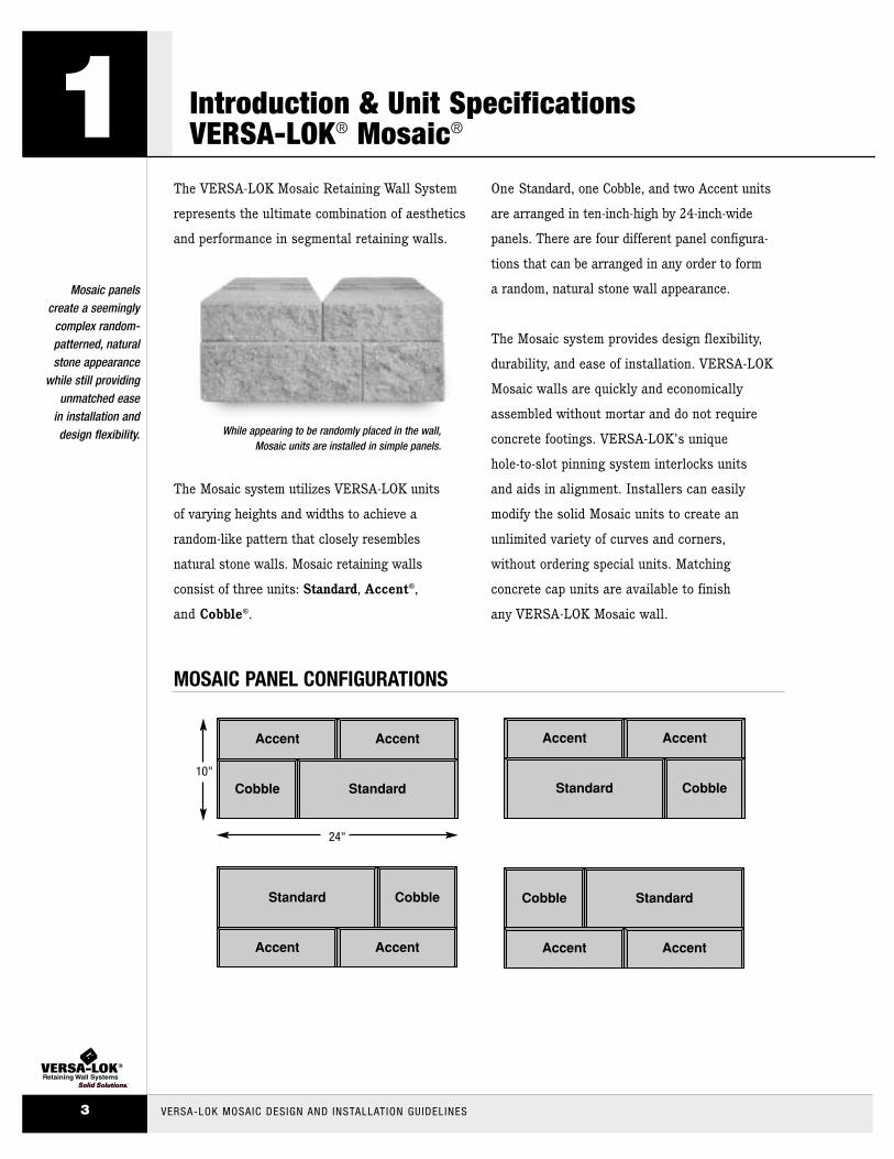
One Standard, one Cobble, and two Accent units
are arranged in ten-inch-high by 24-inch-wide
panels. There are four different panel configura-
tions that can be arranged in any order to form
a random, natural stone wall appearance.
The Mosaic system provides design flexibility,
durability, and ease of installation. VERSA-LOK
Mosaic walls are quickly and economically
assembled without mortar and do not require
concrete footings. VERSA-LOK's unique
hole-to-slot pinning system interlocks units
and aids in alignment. Installers can easily
modify the solid Mosaic units to create an
unlimited variety of curves and corners,
without ordering special units. Matching
concrete cap units are available to finish
any VERSA-LOK Mosaic wall.
1Mosaic panels
create a seeminglycomplex random-patterned, naturalstone appearance
while still providingunmatched ease
in installation anddesign flexibility.
VERSA-LOK MOSAIC DESIGN AND INSTALLATION GUIDELINES3
Introduction & Unit SpecificationsVERSA-LOK® Mosaic®
Standard Cobble
Accent Accent
StandardCobble
Accent Accent
10"
24"
Standard Cobble
Accent Accent
StandardCobble
Accent Accent
MOSAIC PANEL CONFIGURATIONS
While appearing to be randomly placed in the wall,Mosaic units are installed in simple panels.

Introduction & Unit SpecificationsVERSA-LOK® MOSAIC®
Solid VERSA-LOK Mosaic units provide superiordurability and construction stability.
VERSA-LOK MOSAIC DESIGN AND INSTALLATION GUIDELINES 4
1
As an attractive alternative, all three Mosaic
units are offered with a weathered appearance
(left). Weathered™ Mosaic units undergo a
special process to create a rustic old-world
appearance that closely resembles natural stone.
VERSA-LOK Mosaic units are made from high-strength, low-absorption concrete on concrete block
machines. VERSA-LOK Mosaic units’ solid characteristics make them resistant to damage before,
during, and after construction in all climates, including shoreline applications.
12"
4"
12"
12"
6"
16"16"
VERSA-LOK MOSAIC UNITS(Actual unit size and weight may vary slightly by region.)
Standard Accent® Cobble®
Height: 6 inches 152.4 mm 4 inches 101.6 mm 6 inches 152.4 mm
Width (face): 16 inches 406.4 mm 12 inches 304.8 mm 8 inches 203.2 mm
Width (rear): 14 inches 355.6 mm 8 inches 203.2 mm 6 inches 152.4 mm
Depth: 12 inches 304.8 mm 12 inches 304.8 mm 12 inches 304.8 mm
Face Area: 2/3 ft2 0.062 m2 1/3 ft2 0.031 m2 1/3 ft2 0.031 m2
Weight: 82 lbs 37.19 kg 38 lbs 16.33 kg 38 lbs 17.24 kg
Wgt/Face Area: 123 lbs/ft2 599.84 kg/m2 108 lbs/ft2 526.77 kg/m2 114 lbs/ft2 556.13 kg/m2
12"
6"
8"
VERSA-LOK MOSAIC WEATHERED(Available in most areas.)

VERSA-LOK Mosaic units interlock with non-corrosive
VERSA-TUFF® Snap-Off Pins. VERSA-TUFF Pins
are inserted through front holes in the upper units
into slots in the units below. Slots allow variation
in location of vertical joints (variable bond).
Generally, two VERSA-TUFF Snap-Off Pins are
used for each Standard, Accent®, and Cobble®
unit—eight VERSA-TUFF Pins per panel.
VERSA-TUFF Snap-Off Pins are designed to accommodate
varied heights of Mosaic units. The full length of
VERSA-TUFF Pins is used when pinning through
six-inch-high Standard and Cobble units, (Figure A).
When pinning through four-inch-high Accent units,
the two-inches of the VERSA-TUFF Pin remaining
above the unit is easily snapped off (Figure B).
1VERSA-LOK
Mosaic units have a unique hole-to-
slot pin system foreasy installation
and superior structural integrity.
VERSA-LOK MOSAIC DESIGN AND INSTALLATION GUIDELINES5
Introduction & Unit SpecificationsVERSA-LOK® Mosaic®
Cap A Cap B
Pinning Accent toStandard/Cobble
Pinning Standard/Cobble to Accent
3/4"
3/4"
4"
6"
6"
4"
snap offtop of pin
VERSA-TUFF® SNAP-OFF PIN
Length: 6.8 inches 172.7 mm
Snap-Off Length: 4.625 inches 117.5 mm
Diameter: 0.48 inches 12.2 mm
Material: Glass-Reinforced Nylon
VERSA-TUFF Snap-offPins accommodate
varied heights ofMosaic units.
Matching cap units attractively finish VERSA-LOK walls.
VERSA-LOK MOSAIC PINNING
VERSA-LOK CAP UNITS
Weight: A Cap 40 lbs 18.14 kg
B Cap 50 lbs 22.68 kg
Figure A
Figure B
3-5/8"
14" 14"
12"
12"
16"

On many projects, Mosaic retaining
walls work purely as gravity systems,
where unit weight, frictional forces
between units, pins, and the cant of the
wall combine to provide resistance to
earth pressures. With level backfill and
no excessive loading, most Mosaic walls
are stable to four feet in height.
When unit weight and frictional forces
are not enough to resist soil loads,
horizontal layers of geosynthetics are
used to reinforce soil behind walls.
With proper design and soil reinforce-
ment, Mosaic walls can be constructed
to heights exceeding 40 feet.
Each Mosaic unit is set back 3/4-inch
from the units beneath it. There are
two units stacked in each ten-inch-high
panel—a total setback of 1.5 inches
per panel. This results in a cant of
approximately 8.5 degrees from vertical.
VERSA-LOK® Mosaic®
System Overview
VERSA-LOKMosaic’s uniquepanel system provides levelcourses every teninches to easilyaccommodategeogrid layers used in tall wallconstruction.
VERSA-LOK MOSAIC DESIGN AND INSTALLATION GUIDELINES 6
2
Reinforced
Unreinforced
cap unit
mosaicunits
reinforced backfill
12" thick min.drainage
aggregate
geosyntheticreinforcement
cap unit
mosaicunits
VERSA-LOK® MOSAIC–TYPICAL SECTIONS
FoundationFoundation soils on which walls will rest must
be stiff, firm, and have sufficient capacity to
support wall system weight. Any loose, soft,
or compressible material must be removed and
replaced with properly compacted backfill.
The bearing capacity of the foundation soils
should be addressed by a soils engineer.
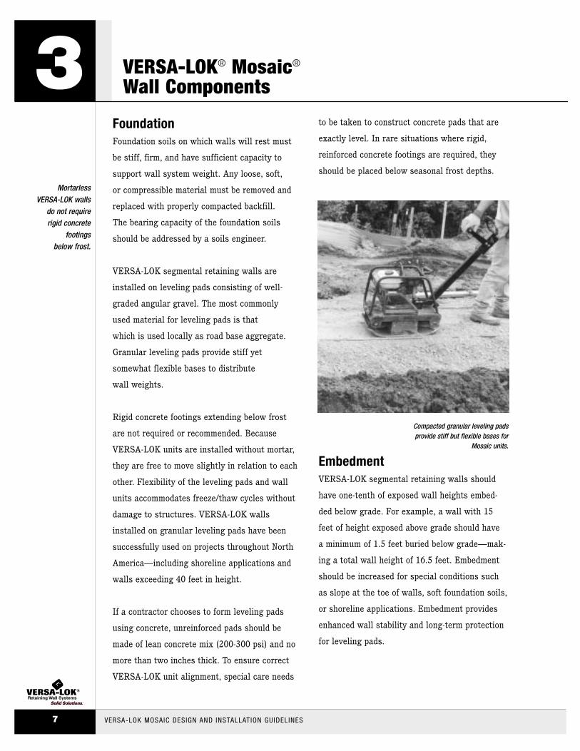
VERSA-LOK segmental retaining walls are
installed on leveling pads consisting of well-
graded angular gravel. The most commonly
used material for leveling pads is that
which is used locally as road base aggregate.
Granular leveling pads provide stiff yet
somewhat flexible bases to distribute
wall weights.
Rigid concrete footings extending below frost
are not required or recommended. Because
VERSA-LOK units are installed without mortar,
they are free to move slightly in relation to each
other. Flexibility of the leveling pads and wall
units accommodates freeze/thaw cycles without
damage to structures. VERSA-LOK walls
installed on granular leveling pads have been
successfully used on projects throughout North
America—including shoreline applications and
walls exceeding 40 feet in height.
If a contractor chooses to form leveling pads
using concrete, unreinforced pads should be
made of lean concrete mix (200-300 psi) and no
more than two inches thick. To ensure correct
VERSA-LOK unit alignment, special care needs
to be taken to construct concrete pads that are
exactly level. In rare situations where rigid,
reinforced concrete footings are required, they
should be placed below seasonal frost depths.
EmbedmentVERSA-LOK segmental retaining walls should
have one-tenth of exposed wall heights embed-
ded below grade. For example, a wall with 15
feet of height exposed above grade should have
a minimum of 1.5 feet buried below grade—mak-
ing a total wall height of 16.5 feet. Embedment
should be increased for special conditions such
as slope at the toe of walls, soft foundation soils,
or shoreline applications. Embedment provides
enhanced wall stability and long-term protection
for leveling pads.
3Mortarless
VERSA-LOK wallsdo not requirerigid concrete
footings below frost.
VERSA-LOK MOSAIC DESIGN AND INSTALLATION GUIDELINES7
VERSA-LOK® Mosaic®
Wall Components
Compacted granular leveling padsprovide stiff but flexible bases for
Mosaic units.

Soils and CompactionWith proper design, VERSA-LOK segmental
walls can be constructed within a wide variety
of soil conditions. Granular soils are preferred
as fill in the areas reinforced with geosynthetics;
however, fine-grained soils such as clays are
acceptable. Usually, coarse soils require less
soil reinforcement and are easier to compact
than fine soils. Problem materials like expansive
clays, compressible soils, or highly organic soils
(top soil) should be avoided or properly
addressed in designs.
Proper compaction of foundation and backfill soil
is critical to long-term performance of retaining
wall systems. Loose backfill will add pressure on
walls, collect water, cause settlement, and will
not anchor soil reinforcement materials properly.
Foundation and backfill materials should be
compacted to at least 95 percent of standard
Proctor density. (Proctor density is the maximum
density of the soil achieved in a laboratory
using a standard amount of compaction effort.)
Generally, construction observation and
testing for proper soil type and compaction is
provided by the project’s soils engineer.
Drainage Within WallsSegmental retaining walls are designed
assuming no hydrostatic pressure behind walls.
Drainage aggregate (angular gravel, clear of
fines) placed behind walls helps eliminate water
accumulation. Because no mortar is used in
VERSA-LOK wall construction, water is free to
weep through joints of installed units. For walls
greater than three feet in height, a perforated
drain pipe is recommended at the base of the
drainage aggregate to quickly remove large
amounts of water.
If high groundwater levels are anticipated or if
the wall is along a shoreline, additional drainage
materials behind and below reinforced fill may be
required. Filter fabric may be required to prevent
unwanted migration of fine soil particles into the
drainage aggregate.
Surface DrainageWall sites should be graded to avoid water
flows, concentrations, or pools behind retaining
walls. If swales are designed at the top of
walls, properly line and slope them so water is
removed before it can flow down behind walls.
Give special attention to sources of stormwater
from building roofs, gutter downspouts, paved
areas draining to one point, or valleys in
topography. Be sure to guide flows from these
areas away from retaining walls. Slope the
soil slightly down and away from wall bases
to eliminate water running along bases and
eroding soil. If finish grading, landscaping,
or paving is not completed immediately after
wall installation, temporarily protect the wall
from water runoff until adjacent construction
and drainage control structures are completed.
VERSA-LOK® Mosaic®
Wall Components
Properly compacted soils and drainage controlsare critical components ofMosaic walls.
VERSA-LOK MOSAIC DESIGN AND INSTALLATION GUIDELINES 8
3
Geosynthetic ReinforcementGeosynthetics are durable, high-strength polymer
products designed for use as soil reinforcement.
Horizontal layers of geosynthetic such as
VERSA-Grid® provide tensile strength to hold
the reinforced soil together, so it behaves as
one coherent mass. The geosynthetic reinforced
soil mass becomes the retaining wall. Sufficient
length and strength of geosynthetic can create
a reinforced soil mass large enough and
strong enough to resist destabilizing loads.
Geosynthetic layers also connect the
VERSA-LOK units to the reinforced soil.
Geosynthetics are made from several types of
polymers that resist installation damage and
long-term degradation. Geosynthetics are
designed to interact with the soil for anchorage
against pullout and resistance to sliding.
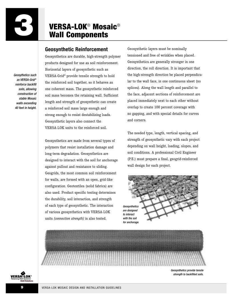
Geogrids, the most common soil reinforcement
for walls, are formed with an open, grid-like
configuration. Geotextiles (solid fabrics) are
also used. Product specific testing determines
the durability, soil interaction, and strength
of each type of geosynthetic. The interaction
of various geosynthetics with VERSA-LOK
units (connection strength) is also tested.
Geosynthetic layers must be nominally
tensioned and free of wrinkles when placed.
Geosynthetics are generally stronger in one
direction, the roll direction. It is important that
the high-strength direction be placed perpendicu-
lar to the wall face, in one continuous sheet (no
splices). Along the wall length and parallel to
the face, adjacent sections of reinforcement are
placed immediately next to each other without
overlap to create 100 percent coverage with
no gapping, and with special details for curves
and corners.
The needed type, length, vertical spacing, and
strength of geosynthetic vary with each project
depending on wall height, loading, slopes, and
soil conditions. A professional Civil Engineer
(P.E.) must prepare a final, geogrid-reinforced
wall design for each project.
3Geosythetics such
as VERSA-Grid®
reinforce backfillsoils, allowing
construction of stable Mosaic
walls exceeding 40 feet in height.
VERSA-LOK MOSAIC DESIGN AND INSTALLATION GUIDELINES9
VERSA-LOK® Mosaic®
Wall Components
Geosynthetics provide tensile strength to backfilled soils.
Geosyntheticsare designedto interact with the soilfor anchorage.

ShorelinesVERSA-LOK® segmental retaining walls
perform well in shoreline applications. However,
special design considerations are often necessary
to ensure that water pressures do not build up
behind walls. Special provisions may include
granular reinforced backfill, additional drainage
aggregate, drainage behind reinforced soil
masses, and filter fabric. Protection of bases
from water scour, wave action, and ice may
also be necessary.
See VERSA-LOK Technical Bulletin #1 for more
information regarding shorelines and retention
pond protection.
Loads Behind WallsSurcharge loads and slopes behind walls can
substantially increase amounts of required
soil reinforcement. Common surcharge loads
include parking areas, driveways, and building
structures. For design purposes, permanent
loads like buildings and slopes are considered to
contribute to both destabilizing and stabilizing
forces acting on walls. Dynamic forces like
vehicular traffic are considered to contribute
to destabilizing forces only. Often, the highest
surcharge loads are caused by grading or paving
equipment during construction. Heavy equipment
should be kept at least three feet behind the
back of retaining wall units. Soil reinforcement
designs should accommodate all anticipated
surcharge loads—even if they will occur
infrequently or just once.
TieringAesthetically, it may sometimes be desirable
to divide large grade changes into tiered wall
sections. However, upper wall tiers can add
surcharge loads to lower walls and necessitate
special designs. To avoid loading lower walls,
upper walls must be set back horizontally at
least twice the height of the lower walls.
If walls are placed closer, lower walls must
be designed to resist the load of upper walls.
Several closely spaced tiered walls can create steep,
unstable slopes. If tiered walls make a grade change
steeper than 2:1 (horizontal: vertical), global slope
stability may need to be reviewed by a qualified soils
engineer. See VERSA-LOK Technical Bulletin #7 for
more information regarding tiered wall construction.
Special Design Considerations
With proper design, Mosaicwalls can accom-modate special site conditions such as waterloads, slopes or surcharges.
VERSA-LOK MOSAIC DESIGN AND INSTALLATION GUIDELINES 10
4
PlanningCareful planning is critical to successful projects.
Prior to design, accurate information needs to
be gathered including soil conditions, proposed
wall heights, topography, groundwater levels,
and surface water conditions. Proper permits,
owner approvals, utility clearances, and
temporary easements should also be obtained
in advance.
Planned wall alignments should be reviewed
for feasibility. Make sure that layouts account
for minimum curve radii, wall setback, and
area needed for geosynthetic soil reinforcement.
Be sure that all wall components fit within
property constraints. Verify that temporary
construction excavations will not undermine
foundation supports of any existing structures
or utilities. Considerations should also be
given to site access for equipment and materials.
EstimatingAccurately estimate and order required materials
including VERSA-LOK® units, VERSA-TUFF®
Snap-Off Pins, cap units, VERSA-LOK Concrete
Adhesive, imported backfill, leveling pad
materials, VERSA-Grid® geosynthetic soil
reinforcement, drainage aggregate, and
additional drainage materials. The Mosaic®
Unit Estimation Chart on page 12 shows how
to determine quantities of the various Mosaic
units. See the Material Estimation Worksheet
on page 29 to help determine quantities of all
VERSA-LOK products.
For reinforced-wall projects, the VERSA-Grid
estimation charts on page 30 provide approximate
amounts of geogrid soil reinforcement necessary to
construct walls in various soil and loading conditions.
For tall walls or complex situations, VERSA-LOK staff
engineers can prepare project-specific preliminary
designs for geogrid estimation purposes.
5VERSA-LOK’s
technical staff isavailable to assist
in planning, layout,estimating, and
referrals for finalengineering.
VERSA-LOK MOSAIC DESIGN AND INSTALLATION GUIDELINES11
Planning, Estimating& Final Designs

Planning, Estimating& Final Designs
*This chart does not includeestimates forembedded (buried) units. The quantity ofembedded units(generally allStandard units)should also beadded to thesequantities.
VERSA-LOK MOSAIC DESIGN AND INSTALLATION GUIDELINES 12
5Mosaic® Unit Estimation ChartEach Mosaic panel is 1.66 square feet in wall-face area. For each panel, there is one Standard unit,
two Accent® units, and one Cobble® unit. The following formulas and table may be used to estimate
quantities of units required for a Mosaic retaining wall project.
VERSA-LOK MOSAIC QUANTITY ESTIMATION CHART*
10 12 14 16 18 20 22 24 26 28 30feet feet feet feet feet feet feet feet feet feet feet
10 inches Standard 5 6 7 8 9 10 11 12 13 14 15
Cobble 5 6 7 8 9 10 11 12 13 14 15
Accent 10 12 14 16 18 20 22 24 26 28 30
20 inches Standard 10 12 14 16 18 20 22 24 26 28 30
Cobble 10 12 14 16 18 20 22 24 26 28 30
Accent 20 24 28 32 36 40 44 48 52 56 60
30 inches Standard 15 18 21 24 27 30 33 36 39 42 45
Cobble 15 18 21 24 27 30 33 36 39 42 45
Accent 30 36 42 48 54 60 66 72 78 84 90
40 inches Standard 20 24 28 32 36 40 44 48 52 56 60
Cobble 20 24 28 32 36 40 44 48 52 56 60
Accent 40 48 56 64 72 80 88 96 104 112 120
No. of STANDARD UNITS =
Wall Square Footage ÷ 1.66No. of ACCENT UNITS =
Wall Square Footage ÷ 1.66 x 2No. of COBBLE UNITS =
Wall Square Footage ÷ 1.66
ExposedWall
Length
Exposed Wall
Height
12"
4"
12"
12"
6"
16"16"
12"
6"
8"
EACH PANEL REQUIRES 8 PINS

Final DesignsFinal wall designs may be provided prior to
putting projects out for bidding. Alternatively,
wall portions of projects can be specified
design/build. With design/build projects, engi-
neers/architects provide wall layout information
(line and grade) but not final engineering for
the wall. Contractors submit bids based on
this layout including estimated labor, materials,
and final engineering costs. Contractors who
are awarded projects retain licensed engineers
to prepare final wall designs and submit shop
drawings for approval from project
engineers/architects.
As with all proposed construction, a soils report
prepared by a qualified geotechnical engineer is
required to provide adequate information for
proper design. The soils report should address
overall stability of planned grade changes and
allowable bearing capacity of foundation soils.
The report should also include information about
reinforced and retained soil properties.
For assistance in specifying, designing, and
engineering VERSA-LOK® walls, sample wall
specifications are provided on pages 32 to 38
and sample construction details are provided
on pages 39 to 42. Additional details and
specifications are available in electronic format:
Call (800) 770-4525 for more information or visit
our website at www.versa-lok.com. VERSA-LOK’s
technical staff is also available to assist with
planning, layout, preliminary engineering, and
referrals for final engineering.
For walls more than four feet in height, most building
codes require a final wall design prepared by a
licensed Civil Engineer (P. E.) registered in that state.
VERSA-LOK and its manufacturers have a network
of licensed Civil Engineers who are familiar with
segmental retaining wall design. These individuals
are available for referrals to architects, engineers,
or contractors with final wall design needs.
5For walls over four feet high,
a licensed professional civil
engineer (P.E.)should prepare
the final wall design.
VERSA-LOK MOSAIC DESIGN AND INSTALLATION GUIDELINES13
Planning, Estimating& Final Designs
ToolsThe following tools may be helpful during
construction of Mosaic® segmental retaining walls:
VERSA-Lifter®
Block Splitter
Safety Protection
Vibratory Plate Compactor
Diamond-Blade Concrete Saw
Caulking Gun
Backhoe or Skid-Steer Loader
Four-Foot Level
String Line
Hand Tamper
Transit or Site Level
Finishing Trowel
Tape Measure
Four-Pound Sledge Hammer
Broom
Brick Hammer
Shovel
Three-Inch Masonry Chisel
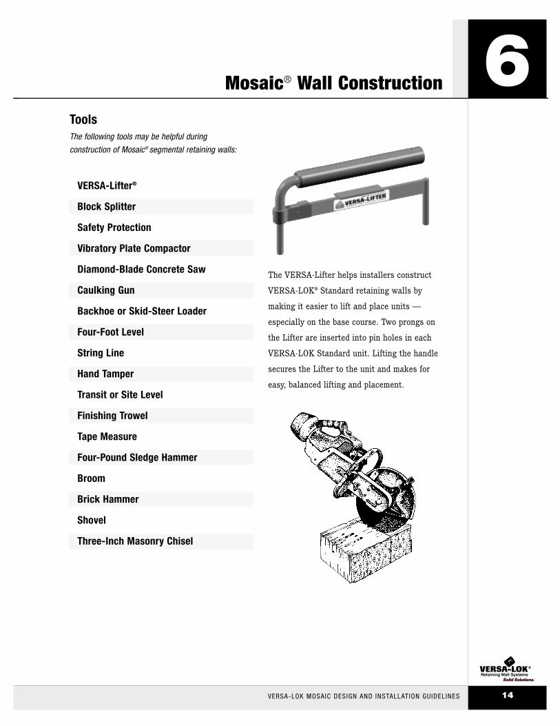
The VERSA-Lifter helps installers construct
VERSA-LOK® Standard retaining walls by
making it easier to lift and place units —
especially on the base course. Two prongs on
the Lifter are inserted into pin holes in each
VERSA-LOK Standard unit. Lifting the handle
secures the Lifter to the unit and makes for
easy, balanced lifting and placement.
Mosaic® Wall Construction
VERSA-LOK MOSAIC DESIGN AND INSTALLATION GUIDELINES 14
6
Unit ModificationDuring wall construction, it may be necessary
to split or cut VERSA-LOK® Mosaic® units.
Splitting creates an attractive textured face
on any visible sides of a Mosaic unit that
matches the split-face on the front of the unit.
Saw-cutting creates a smooth straight edge
on a partial unit, so it can fit tightly next to
adjacent units. Remember to always wear
proper safety protection when performing
splitting or cutting operations.
To split units with a masonry chisel and hammer,
mark a path on the unit’s top, bottom, and
back. Score along the top and bottom paths
using the chisel and a heavy hammer. Place the
unit on its face and strike along the back path.
It is easier to split units on the ground than on
a hard surface. The unit should fracture nicely
along the paths. If many splits will be required
for a project, it may be helpful to rent a mechanical
or hydraulic block splitter from your block
supplier or rental center.
Saw-cuts are normally made using a gas-powered
cut-off saw with a diamond blade. Before you
saw-cut a unit, mark a line on each side to be
cut. Place the unit face toward you with the top
side up, at a comfortable height on a stable work
surface. Make a straight cut down and two to
three inches into the face. Move saw to top of
unit, and cut through top using successively
deeper cuts. Flip unit over and finish by cutting
completely through the bottom of the unit.
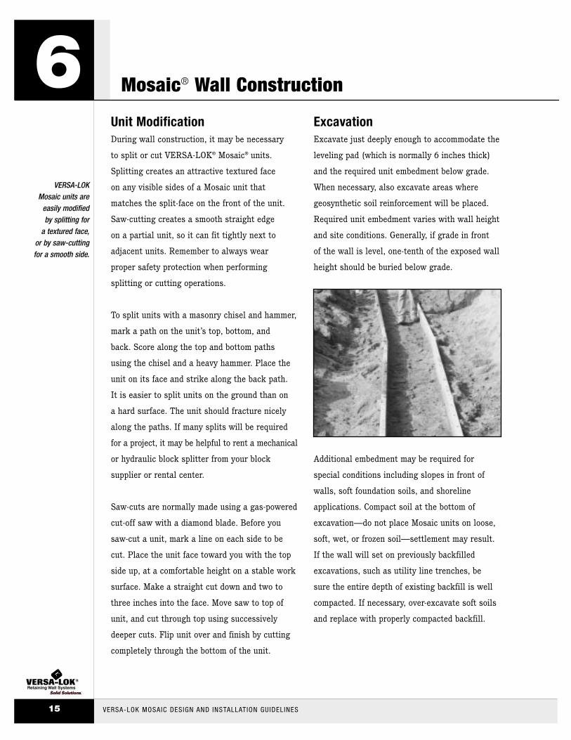
ExcavationExcavate just deeply enough to accommodate the
leveling pad (which is normally 6 inches thick)
and the required unit embedment below grade.
When necessary, also excavate areas where
geosynthetic soil reinforcement will be placed.
Required unit embedment varies with wall height
and site conditions. Generally, if grade in front
of the wall is level, one-tenth of the exposed wall
height should be buried below grade.
Additional embedment may be required for
special conditions including slopes in front of
walls, soft foundation soils, and shoreline
applications. Compact soil at the bottom of
excavation—do not place Mosaic units on loose,
soft, wet, or frozen soil—settlement may result.
If the wall will set on previously backfilled
excavations, such as utility line trenches, be
sure the entire depth of existing backfill is well
compacted. If necessary, over-excavate soft soils
and replace with properly compacted backfill.
6VERSA-LOK
Mosaic units areeasily modified by splitting for
a textured face,or by saw-cutting for a smooth side.
VERSA-LOK MOSAIC DESIGN AND INSTALLATION GUIDELINES15
Mosaic® Wall Construction

Leveling PadPlace granular leveling pad material and
compact to a smooth, level surface. Leveling
pad should be at least six inches thick and 24
inches wide. It should consist of crushed stone.
The most commonly used material for leveling
pads is what is used locally as road base aggre-
gate. To construct long sections of leveling pad,
create forms by leveling and staking rectangular
metal tubing along both sides of the planned
pad. Place and compact granular material within
these leveled forms and screed off excess.
Always begin at the lowest level and work
upward in situations where the planned grade
along the wall front changes elevation. Use a
thin layer of fine sand on top of the leveling
pad for final leveling.
See VERSA-LOK® Technical Bulletin #5
for more tips on leveling pad construction.
Base CourseMake sure that the leveling pad is level and
begin placing base course units. For ease of
installation, use only VERSA-LOK Standard
units for the base course. This will create a
uniform “platform” on which to build the
Mosaic® panels.
Align base units using their backs or slots,
rather than their irregularly textured front faces.
String lines may also be helpful when aligning
straight walls. Place units side by side on the
leveling pad. Fronts of adjacent units should
fit tightly and unit bottoms should contact the
leveling pad completely. Using a four-foot level,
level all units front to back, side to side, and
with adjacent units. Take time to ensure a level
base course—minor unevenness in the base
course will be amplified and difficult to correct
after several courses of panels have been
installed. After the base course has been
positioned, place and compact soil backfill
behind units. Also replace and compact over-
excavated soil in front of the units. Backfill
placed behind and in front of embedded units
should consist of soil, not drainage aggregate.
Mosaic® Wall Construction
Take time to ensure a level basecourse—minorunevenness in thebase course will be amplified anddifficult to correctafter several courses of panels have been installed.
VERSA-LOK MOSAIC DESIGN AND INSTALLATION GUIDELINES 16
6
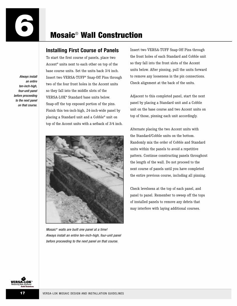
Installing First Course of PanelsTo start the first course of panels, place two
Accent® units next to each other on top of the
base course units. Set the units back 3/4 inch.
Insert two VERSA-TUFF® Snap-Off Pins through
two of the four front holes in the Accent units
so they fall into the middle slots of the
VERSA-LOK® Standard base units below.
Snap-off the top exposed portion of the pins.
Finish this ten-inch-high, 24-inch-wide panel by
placing a Standard unit and a Cobble® unit on
top of the Accent units with a setback of 3/4 inch.
Insert two VERSA-TUFF Snap-Off Pins through
the front holes of each Standard and Cobble unit
so they fall into the front slots of the Accent
units below. After pinning, pull the units forward
to remove any looseness in the pin connections.
Check alignment at the back of the units.
Adjacent to this completed panel, start the next
panel by placing a Standard unit and a Cobble
unit on the base course and two Accent units on
top of those, pinning each unit accordingly.
Alternate placing the two Accent units with
the Standard/Cobble units on the bottom.
Randomly mix the order of Cobble and Standard
units within the panels to avoid a repetitive
pattern. Continue constructing panels throughout
the length of the wall. Do not proceed to the
next course of panels until you have completed
the entire previous course, including all pinning.
Check levelness at the top of each panel, and
panel to panel. Remember to sweep off the tops
of installed panels to remove any debris that
may interfere with laying additional courses.
6Always install
an entire ten-inch-high,four-unit panel
before proceedingto the next panel
on that course.
VERSA-LOK MOSAIC DESIGN AND INSTALLATION GUIDELINES17
Mosaic® Wall Construction
Mosaic® walls are built one panel at a time!
Always install an entire ten-inch-high, four-unit panel
before proceeding to the next panel on that course.

Pinning Mosaic® PanelsTwo VERSA-TUFF® Snap-Off Pins are normally
used for each unit in a Mosaic panel, making
a total of eight VERSA-TUFF Pins per panel.
Because of the variable bond and offset
placement of panels that occurs in the Mosaic
pattern, sometimes only one VERSA-TUFF Pin
will fit into a lower unit—resulting in less
than eight VERSA-TUFF Pins per panel.
Make sure VERSA-TUFF Pins are fully seated
in slots of lower units. If necessary, seat
VERSA-TUFF Pins using a mallet and another
VERSA-TUFF Pin. For six-inch-high Standard
and Cobble® units, VERSA-TUFF Pins are fully
seated when they are recessed below the top
surface of units. For Accent® units, the top
two inches of the pin will initially stick out of
the unit. Snap off this exposed section of the
VERSA-TUFF Pin by hitting the top of the pin
from the side.
Always pin to the front slots in the Accent
and Cobble units and to rear slots in the
VERSA-LOK® Standard unit. Each Mosaic
unit sets back 3/4 inch from the unit below,
regardless of its height. Because the completed
Mosaic panel is two units high, there is a
combined 1.5 inch total setback per ten-inch-
high panel, resulting in an approximate
8.5 degree batter (cant) from vertical.
Mosaic® Wall Construction
VERSA-LOK’sunique hole-to-slotpinning systemallows for easy top-down pinningand variation in the bond of the panels.
VERSA-LOK MOSAIC DESIGN AND INSTALLATION GUIDELINES 18
6
Installing Additional Courses of PanelsWhen there is no fixed starting point, start
the next ten-inch-high course by staggering
the panels at least four inches from the vertical
joints between the panels below. Patterns in
the Mosaic® panels should not line up with the
course below it. Vary this bond on subsequent
courses of panels to create a random look.
Pin units within each panel and to the panels
below as described previously. When laying
additional courses of panels that start at a
corner, wall panel locations will be dictated
by the corner panels.
Pull units forward to remove any looseness in
the pin connections. Check the alignment at the
top of each course of panels and adjust as
needed. Stack no more than two courses of
panels (20 inches high) before backfilling. If too
many panels are placed without backfilling, the
panels will be unstable and may push out of
alignment during backfilling. If course panels
must fit into a limited horizontal space, adjust
by placing a partial panel (less than 24 inches
wide). Saw cut both top and bottom units on
one side of the panel to create a panel with
the needed width.
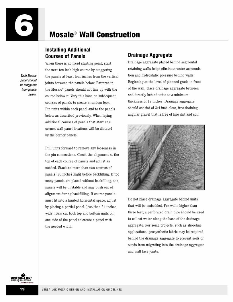
Drainage AggregateDrainage aggregate placed behind segmental
retaining walls helps eliminate water accumula-
tion and hydrostatic pressure behind walls.
Beginning at the level of planned grade in front
of the wall, place drainage aggregate between
and directly behind units to a minimum
thickness of 12 inches. Drainage aggregate
should consist of 3/4-inch clear, free-draining,
angular gravel that is free of fine dirt and soil.
Do not place drainage aggregate behind units
that will be embedded. For walls higher than
three feet, a perforated drain pipe should be used
to collect water along the base of the drainage
aggregate. For some projects, such as shoreline
applications, geosynthetic fabric may be required
behind the drainage aggregate to prevent soils or
sands from migrating into the drainage aggregate
and wall face joints.
6Each Mosaic panel should be staggered from panels
below.
VERSA-LOK MOSAIC DESIGN AND INSTALLATION GUIDELINES19
Mosaic® Wall Construction
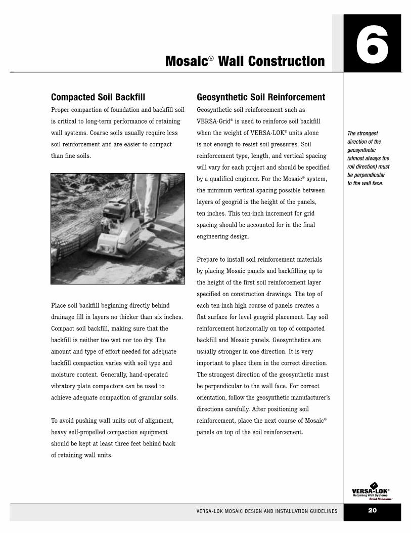
Compacted Soil Backfill Proper compaction of foundation and backfill soil
is critical to long-term performance of retaining
wall systems. Coarse soils usually require less
soil reinforcement and are easier to compact
than fine soils.
Place soil backfill beginning directly behind
drainage fill in layers no thicker than six inches.
Compact soil backfill, making sure that the
backfill is neither too wet nor too dry. The
amount and type of effort needed for adequate
backfill compaction varies with soil type and
moisture content. Generally, hand-operated
vibratory plate compactors can be used to
achieve adequate compaction of granular soils.
To avoid pushing wall units out of alignment,
heavy self-propelled compaction equipment
should be kept at least three feet behind back
of retaining wall units.
Geosynthetic Soil ReinforcementGeosynthetic soil reinforcement such as
VERSA-Grid® is used to reinforce soil backfill
when the weight of VERSA-LOK® units alone
is not enough to resist soil pressures. Soil
reinforcement type, length, and vertical spacing
will vary for each project and should be specified
by a qualified engineer. For the Mosaic® system,
the minimum vertical spacing possible between
layers of geogrid is the height of the panels,
ten inches. This ten-inch increment for grid
spacing should be accounted for in the final
engineering design.
Prepare to install soil reinforcement materials
by placing Mosaic panels and backfilling up to
the height of the first soil reinforcement layer
specified on construction drawings. The top of
each ten-inch high course of panels creates a
flat surface for level geogrid placement. Lay soil
reinforcement horizontally on top of compacted
backfill and Mosaic panels. Geosynthetics are
usually stronger in one direction. It is very
important to place them in the correct direction.
The strongest direction of the geosynthetic must
be perpendicular to the wall face. For correct
orientation, follow the geosynthetic manufacturer’s
directions carefully. After positioning soil
reinforcement, place the next course of Mosaic®
panels on top of the soil reinforcement.
Mosaic® Wall Construction
The strongestdirection of thegeosynthetic(almost always theroll direction) mustbe perpendicular to the wall face.
VERSA-LOK MOSAIC DESIGN AND INSTALLATION GUIDELINES 20
6

Insert pins through the bottom panel units,
through the geosynthetic, and into the slots of
the panel below. Place drainage aggregate
against the back of the units and on top of the
soil reinforcement. Remove slack by pulling soil
reinforcement away from the wall face and
anchoring at back ends. Beginning at the
drainage aggregate, place and compact soil
backfill. Keep soil reinforcement taut and avoid
wrinkles. Place a minimum of ten inches of soil
backfill before using any tracked equipment on
top of soil reinforcement. Placing soil reinforce-
ment behind curves and corners requires special
layout and overlapping procedures. Never overlap
soil reinforcement layers directly on top of each
other—always provide at least three inches of soil
fill between overlapping soil reinforcement layers.
See VERSA-LOK® Technical Bulletin #3 for
more curve/corner soil reinforcement details.
CapsFinish Mosaic retaining walls by placing stan-
dard VERSA-LOK cap units along the top of the
wall. Two cap units are available—Type A and
Type B. Alternate A and B caps on straight
walls. Use A caps for convex (outside) curves.
Use B caps for concave (inside) curves. Front
faces of caps may be placed flush, set back, or
slightly extended over faces of VERSA-LOK
Mosaic units. Caps are secured with two continu-
ous, 1/4-inch beads of VERSA-LOK Concrete
Adhesive placed along the top course of wall
units. Set and press the caps onto these pre-
pared wall units.
See VERSA-LOK® Technical Bulletin #4 for more
about capping.
6Keep geosynthetic
taut and removeany slack by
pulling it away from the wall face.
VERSA-LOK MOSAIC DESIGN AND INSTALLATION GUIDELINES21
Mosaic® Wall Construction

CurvesCurves in a Mosaic® wall are created by fanning
apart or bringing together the backs of units.
The trapezoidal shape of Mosaic units permits
a wide range in radii of convex, concave, and
serpentine curves. However, convex (outside)
curves in Mosaic walls cannot be built tighter
than an eight-foot radius. Also, concave
(inside) curves built with less than
a six-foot radius look ragged in
appearance. An inside corner
is recommended in place
of a tight inside curve.
When constructing curves,
install each ten-inch-high
panel completely before
proceeding to the adjacent
panel. Generally, keep the
vertical joints at the front of
units tight-fitting. There will,
however, be some minor gapping
between units in curved Mosaic
walls to account for changes in curve
radii as courses set back.
Concave (Inside) CurvesConstruct concave curves by increasing spaces
between the backs of units. For a smooth curve,
concave curves should have a minimum six-foot
radius at the bottom of the wall.
Some slight gapping is needed between upper
units of panels to adjust to changing radii.
Upper units in a panel set back from the lower
units, so upper units curve on a slightly bigger
circle. Because upper units in a panel must
cover longer distances, upper units must be
spread out (gapped) to match the layout of
the lower units.
This is why it is important to build and adjust
a complete ten-inch-high by 24-inch-wide panel
before installing any adjacent panels.
For more information on building curved walls,
see VERSA-LOK® Technical Bulletin #3 – Curves
and Corners.
Basic Wall Design Elements
Minor gappingbetween someunits is necessaryto account forchanges in thecurve radius as each course sets back.
VERSA-LOK MOSAIC DESIGN AND INSTALLATION GUIDELINES 22
7
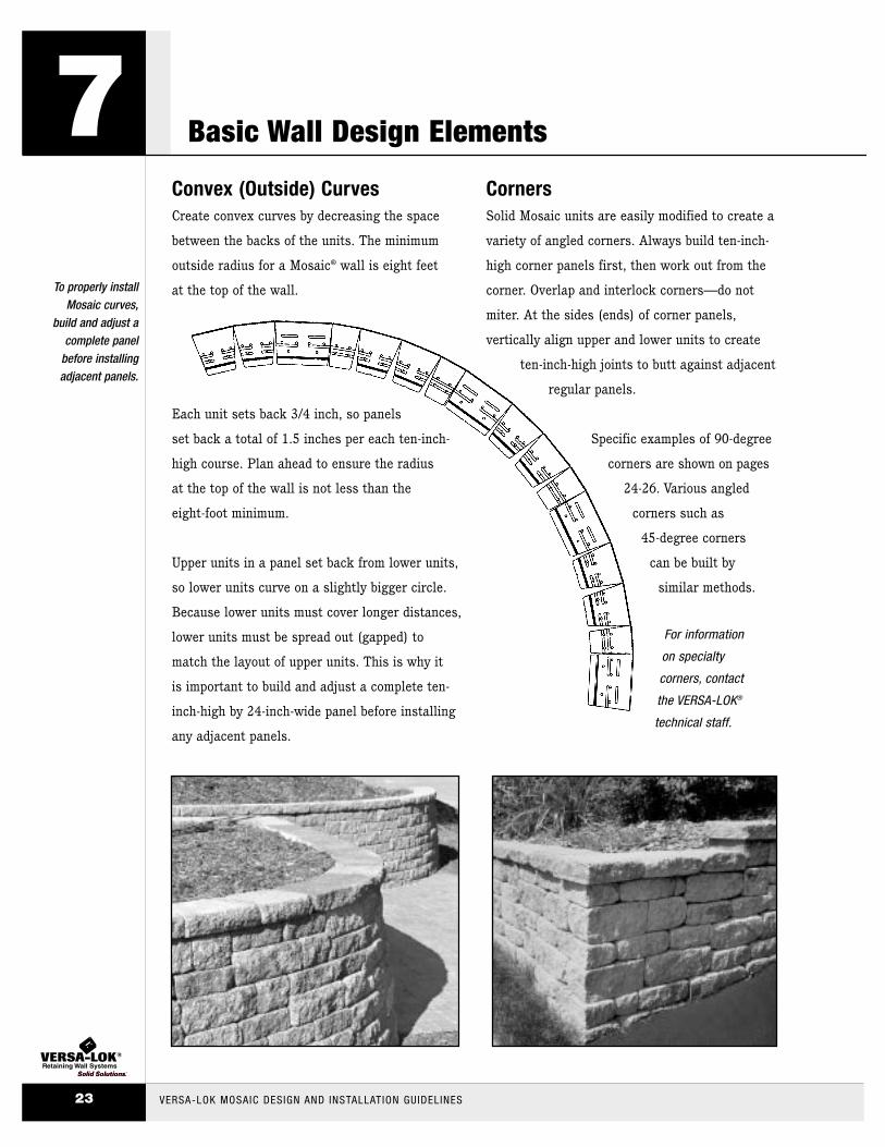
Convex (Outside) CurvesCreate convex curves by decreasing the space
between the backs of the units. The minimum
outside radius for a Mosaic® wall is eight feet
at the top of the wall.
Each unit sets back 3/4 inch, so panels
set back a total of 1.5 inches per each ten-inch-
high course. Plan ahead to ensure the radius
at the top of the wall is not less than the
eight-foot minimum.
Upper units in a panel set back from lower units,
so lower units curve on a slightly bigger circle.
Because lower units must cover longer distances,
lower units must be spread out (gapped) to
match the layout of upper units. This is why it
is important to build and adjust a complete ten-
inch-high by 24-inch-wide panel before installing
any adjacent panels.
CornersSolid Mosaic units are easily modified to create a
variety of angled corners. Always build ten-inch-
high corner panels first, then work out from the
corner. Overlap and interlock corners—do not
miter. At the sides (ends) of corner panels,
vertically align upper and lower units to create
ten-inch-high joints to butt against adjacent
regular panels.
Specific examples of 90-degree
corners are shown on pages
24-26. Various angled
corners such as
45-degree corners
can be built by
similar methods.
For information
on specialty
corners, contact
the VERSA-LOK®
technical staff.
7To properly install
Mosaic curves,build and adjust a
complete panelbefore installingadjacent panels.
VERSA-LOK MOSAIC DESIGN AND INSTALLATION GUIDELINES23
Basic Wall Design Elements

Outside 90o CornerFor the first ten-inch high corner panel, split a
Standard unit and an Accent® unit into halves.
Next, cut off the backs of two of the split half
units as shown (Figure A and B). Also cut or
split off the rear corner of a whole Standard unit
(Figure A). For the lower portion of the corner
panel, place the modified half-Standard unit at
the corner. Place the corner-cut Standard unit
and a Cobble® unit at its sides (Figure A).
For the upper portion, place the modified half-
Accent unit at the corner, with whole Accent
units at both sides (Figure B). Complete this
ten-inch-high course by building out from the
corner panel with Mosaic® panels. On the next
course, install another ten-inch-high corner
panel that is basically the mirror image of
the first course corner panel (Figures C & D).
For the remaining courses, repeat these
corner panels until reaching desired wall height.
Basic Wall Design Elements
For each course,always build a ten-inch high corner panel first, then work out from this corner panel.
VERSA-LOK MOSAIC DESIGN AND INSTALLATION GUIDELINES 24
7
6"
8"
111/4"
103/4"
8"
6"
103/4"
111/4"
split and cutAccent unit
split and cutStandard unit
cut Standard unit
split and cutAccent unit
split and cut Standard unit
cut Standard
unit
SecondCourse 10"
10"
FirstCourse
UPPER
LOWERA
B UPPER
LOWERC
D
First Course Second Course

Outside 90o Corner at StairsWhen building an outside corner at stairs, the
side wall abutting the stairs should be vertical
(see page 29). For the first ten-inch-high corner
panel, split a Standard and an Accent® unit
into halves and cut off the back of the Standard
half unit as shown (Figure A). Also cut or
split off the rear corner of a whole Standard unit
(Figure A). Place the half-Standard unit at
the corner, with a corner-cut Standard unit and
a Cobble® unit at its side (Figure A). Above
this, place the half-Accent unit at the corner,
with whole Accent units at both sides (Figure B).
On the next course, install another ten-inch-high
corner panel similar to the first course panel
(Figures C & D). For the remaining courses,
repeat these corner panels until reaching
desired wall height.
7For corners at
stairs, the frontwall sets back
but the side wall is vertical.
VERSA-LOK MOSAIC DESIGN AND INSTALLATION GUIDELINES25
Basic Wall Design Elements
CornerPanels
6"
12"
103/4"
8"
UPPER
LOWER
10"
111/4"
6"
A
B UPPER
LOWERC
D
VERSA-LOK Standard Units
VERSA-LOK Mosaic Constructed
3/4" Setback
VERSA-LOK MosaicSidewalls Constructed
Vertically
Cap Units NotShown For Clarity
First Course Second Course

Inside 90o CornersFor the first ten-inch-high course of a 90-degree
inside corner, butt the left side panel into the
right side panel (Figures A & B). This hides
part of the right side panel that runs “wild” past
the corner. Upper and lower portions of both
panels meeting at the corner should have units
of the same height. In the illustrations below,
lower units of the first-course corner panels are
all four inches high. Modify the left side panel
to fit snugly against the setback in the right
side panel face by saw cutting 3/4 inch off the
lower unit (Figure A). Build regular Mosaic®
panels out from the corner panels to complete
the first course. On the second course, butt the
right side panel into the left side panel and saw
cut the lower right side unit (Figures C & D).
For remaining courses, repeat these corner
panels until reaching desired wall height.
Basic Wall Design Elements
For inside corners,saw-cut units in the abutting panels to fit snuggly against the setback within the adjacent panels.
VERSA-LOK MOSAIC DESIGN AND INSTALLATION GUIDELINES 26
7
10"
CUT OFF 3/4"
11-1/4"15-1/4"
CUT OFF 3/4"
Cut 3/4 inch from lower panel unit to
accommodate setback in face of adjacent panel.
CornerPanels
FirstCourse
10"
SecondCourse
UPPER
LOWERA
B UPPER
LOWERC
D
First Course Second Course

Stepping Top of WallWall tops should step to match grade changes. If a Mosaic® wall steps down six inches, use a modified
Standard unit at the transition. Split a Standard unit in half so the textured wall end will match the
wall face. When a step is four inches, splitting the Accent® unit is not necessary. The sides of two cap
units should also be split to maintain texture on wall ends.
Stepping Base of WallIf the planned grade along the front of a Mosaic wall changes elevation, the leveling pad should be
stepped in ten-inch increments to match the grade change. Always start wall construction at its lowest
level and work upward. Step the leveling pad only often enough to avoid burying extra units while
maintaining required minimum unit embedment. With the Mosaic pattern, always build with full
ten-inch-high panels after base course installation.
Some of the base course of VERSA-LOK® Standard units can show above grade without changing the
random look of the wall face pattern.
7Create attractive
step-downs bysplitting sides
of caps and Standard units.
VERSA-LOK MOSAIC DESIGN AND INSTALLATION GUIDELINES27
Basic Wall Design Elements
Leveling pad
6" STEP
Split Cap Unit
Split Standard Unit Split Cap Unit
10" STEP
4" STEP
10" STEP
Embedded Base Course(standard units)
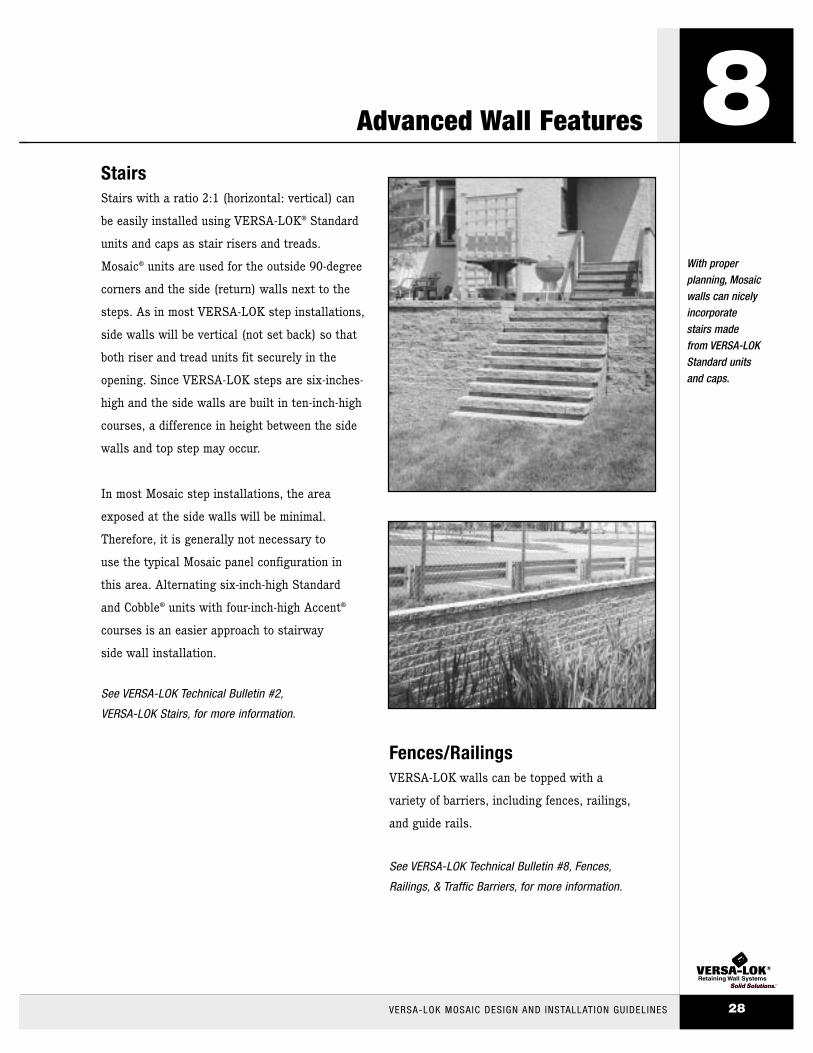
Stairs Stairs with a ratio 2:1 (horizontal: vertical) can
be easily installed using VERSA-LOK® Standard
units and caps as stair risers and treads.
Mosaic® units are used for the outside 90-degree
corners and the side (return) walls next to the
steps. As in most VERSA-LOK step installations,
side walls will be vertical (not set back) so that
both riser and tread units fit securely in the
opening. Since VERSA-LOK steps are six-inches-
high and the side walls are built in ten-inch-high
courses, a difference in height between the side
walls and top step may occur.
In most Mosaic step installations, the area
exposed at the side walls will be minimal.
Therefore, it is generally not necessary to
use the typical Mosaic panel configuration in
this area. Alternating six-inch-high Standard
and Cobble® units with four-inch-high Accent®
courses is an easier approach to stairway
side wall installation.
See VERSA-LOK Technical Bulletin #2,
VERSA-LOK Stairs, for more information.
Fences/RailingsVERSA-LOK walls can be topped with a
variety of barriers, including fences, railings,
and guide rails.
See VERSA-LOK Technical Bulletin #8, Fences,
Railings, & Traffic Barriers, for more information.
Advanced Wall Features
With proper planning, Mosaicwalls can nicelyincorporate stairs made from VERSA-LOKStandard units and caps.
VERSA-LOK MOSAIC DESIGN AND INSTALLATION GUIDELINES 28
8
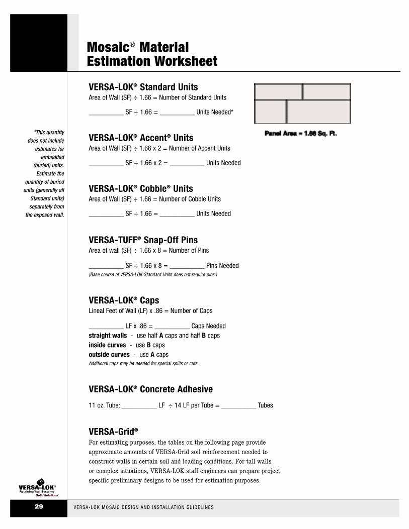
VERSA-LOK® Standard UnitsArea of Wall (SF) ÷ 1.66 = Number of Standard Units
__________ SF ÷ 1.66 = __________ Units Needed*
VERSA-LOK® Accent® UnitsArea of Wall (SF) ÷ 1.66 x 2 = Number of Accent Units
__________ SF ÷ 1.66 x 2 = __________ Units Needed
VERSA-LOK® Cobble® UnitsArea of Wall (SF) ÷ 1.66 = Number of Cobble Units
__________ SF ÷ 1.66 = __________ Units Needed
VERSA-TUFF® Snap-Off PinsArea of wall (SF) ÷ 1.66 x 8 = Number of Pins
__________ SF ÷ 1.66 x 8 = __________ Pins Needed(Base course of VERSA-LOK Standard Units does not require pins.)
VERSA-LOK® CapsLineal Feet of Wall (LF) x .86 = Number of Caps
__________ LF x .86 = __________ Caps Needed straight walls - use half A caps and half B capsinside curves - use B capsoutside curves - use A capsAdditional caps may be needed for special splits or cuts.
VERSA-LOK® Concrete Adhesive
11 oz. Tube: __________ LF ÷ 14 LF per Tube = __________ Tubes
VERSA-Grid®
For estimating purposes, the tables on the following page provide
approximate amounts of VERSA-Grid soil reinforcement needed to
construct walls in certain soil and loading conditions. For tall walls
or complex situations, VERSA-LOK staff engineers can prepare project
specific preliminary designs to be used for estimation purposes.
*This quantity does not include
estimates forembedded
(buried) units. Estimate the
quantity of buriedunits (generally all
Standard units)separately from
the exposed wall.
VERSA-LOK MOSAIC DESIGN AND INSTALLATION GUIDELINES29
Mosaic® Material Estimation Worksheet

VERSA-GRID® Estimation Charts
VERSA-LOK MOSAIC DESIGN AND INSTALLATION GUIDELINES 30
These tables are provided for estimating purposes only. They should not be used or relied upon for any application without verification of accuracy, suitability, and applicability for the use contemplated, which is the sole responsibility of the user. Afinal, project specific design should be prepared by a qualified, licensed, professionalCivil Engineer (P. E.) based on actual site conditions. Preparation of these tables did not include consideration or analysis of global slope stability or allowable bearing capacity of foundation soils. These must be reviewed for each project by a qualifiedGeotechnical Engineer.
There are three tables provided in this guide to help estimate geogrid for different wall loading situations – level backfill, sloping backfill, and surcharges. To estimategeogrid quantities, first look under the column appropriate for project soils, determinethe height (H) of the proposed wall and read across the row (under appropriate soil column) to approximate geogrid type, number of layers, and lengths of each layer.
These design charts assume the following conditions:
- Uniform soil conditions
- Stable foundation soils
- Level grade in front of the wall
- No groundwater/water loads
- Slopes and loads behind the wall as shown
- No additional loading behind wall (such as tiered walls,
building loads, etc.)
Design standards and properties used to develop these charts were:
- Design methodology - in general accordance with NCMA
Design Manual for SRWs
- Unit weight of soil (γ) 120 pcf
- Internal friction angle of soil (φ)as shown on charts
- Long term design strength of the geogrid (LTDS)
• VERSA-Grid VG 3.0 - 1250 lb/ft• VERSA-Grid VG 5.0 - 1875 lb/ft
*Geogrids with similar LTDS and connection strengths to VERSA-LOK units can also be estimated using these charts.With some variations, the VERSA-Grid VG 3.0 charts also generally estimate quantities for Miragrid 3XT, Stratagrid 300,
and Raugrid 4/2. The charts for VERSA-Grid VG 5.0 generally estimate quantities for Miragrid 5XT, Stratagrid 500, and Raugrid 6/3.
Gravel (φ = 34°)
H (feet) D (feet) L (feet) layers VERSA-Grid
4 0.5 0 0 n/a
5 0.5 3.5 2 VG 3.0
6 0.5 4.0 2 VG 3.0
7 1.0 5.0 3 VG 3.0
8 1.0 5.5 4 VG 3.0
9 1.0 6.0 4 VG 3.0
10 1.0 6.5 5 VG 3.0
12 1.0 8.0 6 VG 3.0
Sand (φ = 30°)
H (feet) D (feet) L (feet) layers VERSA-Grid
4 0.5 4.0 1 VG 3.0
5 0.5 4.0 2 VG 3.0
6 0.5 4.5 2 VG 3.0
7 1.0 5.5 3 VG 3.0
8 1.0 6.0 4 VG 3.0
9 1.0 6.5 5 VG 3.0
10 1.0 7.0 5 VG 3.0
12 1.0 8.5 7 VG 3.0
Clay (φ = 28°)
H (feet) D (feet) L (feet) layers VERSA-Grid
4 0.5 4.0 1 VG 3.0
5 0.5 4.5 2 VG 3.0
6 0.5 5.0 2 VG 3.0
7 1.0 5.5 3 VG 3.0
8 1.0 6.0 4 VG 3.0
9 1.0 6.5 5 VG 3.0
10 1.0 7.0 6 VG 3.0
12 1.0 8.5 7 VG 3.0
Gravel (φ = 34°)
H (feet) D (feet) L (feet) layers VERSA-Grid
4 0.5 4.0 2 VG 3.0
5 0.5 4.5 2 VG 3.0
6 0.5 5.0 3 VG 3.0
7 1.0 6.0 4 VG 3.0
8 1.0 6.5 4 VG 3.0
9 1.0 7.0 5 VG 3.0
10 1.0 7.5 5 VG 3.0
12 1.0 9.0 7 VG 3.0
Sand (φ = 30°)
H (feet) D (feet) L (feet) layers VERSA-Grid
4 0.5 4.5 2 VG 3.0
5 0.5 5.5 2 VG 3.0
6 0.5 6.0 3 VG 3.0
7 1.0 7.0 4 VG 3.0
8 1.0 7.5 5 VG 3.0
9 1.0 8.5 5 VG 3.0
10 1.0 9.0 6 VG 3.0
12 1.0 10.0 7 VG 5.0
Clay (φ = 28°)
H (feet) D (feet) L (feet) layers VERSA-Grid
4 0.5 5.5 2 VG 3.0
5 0.5 6.0 2 VG 3.0
6 0.5 6.5 3 VG 3.0
7 1.0 7.5 4 VG 3.0
8 1.0 8.0 5 VG 3.0
9 1.0 9.0 5 VG 3.0
10 1.0 9.5 6 VG 3.0
12 1.0 11.0 7 VG 5.0
Gravel (φ = 34°)
H (feet) D (feet) L (feet) layers VERSA-Grid
4 0.5 4.0 1 VG 3.0
5 0.5 4.0 2 VG 3.0
6 0.5 4.5 3 VG 3.0
7 1.0 5.5 4 VG 3.0
8 1.0 6.0 4 VG 3.0
9 1.0 6.5 5 VG 3.0
10 1.0 7.5 6 VG 3.0
12 1.0 8.5 7 VG 3.0
Sand (φ = 30°)
H (feet) D (feet) L (feet) layers VERSA-Grid
4 0.5 4.5 1 VG 3.0
5 0.5 4.5 2 VG 3.0
6 0.5 5.5 3 VG 3.0
7 1.0 6.5 4 VG 3.0
8 1.0 7.0 5 VG 3.0
9 1.0 8.0 6 VG 3.0
10 1.0 8.5 6 VG 3.0
12 1.0 10.0 7 VG 5.0
Clay (φ = 28°)
H (feet) D (feet) L (feet) layers VERSA-Grid
4 0.5 4.5 2 VG 3.0
5 0.5 5.5 2 VG 3.0
6 0.5 6.0 3 VG 3.0
7 1.0 8.0 4 VG 3.0
8 1.0 9.5 5 VG 3.0
9 1.0 11.0 6 VG 3.0
10 1.0 12.0 6 VG 5.0
12 1.0 15.0 7 VG 5.0
250 psf
Miragrid is a registered trademark of Nicolon Corporation. • Stratagrid is a registered trademark of Strata Systems, Inc.Raugrid is a trademark of Lückenhaus Technische Textilien GmbH and Lückenhaus North America, Inc.
20" Max
H
D
L
H
D
L
H
D
L
20" Max
20" Max
Level Backfill
Sloping Backfill
Surcharge Backfill

Design Options Using VERSA-LOK® Mosaic® UnitsAttractive, durable retaining walls can be
constructed using only VERSA-LOK Cobble
or VERSA-LOK Accent units. These units offer
the same features and benefits as VERSA-LOK
Mosaic walls, including:
• Classic split-face texture or Weathered™ Series
• Setback or near-vertical walls
• No mortar or concrete footings required
• Great options for tighter radius projects,such as planting areas and tree rings
Maximum height for an unreinforced VERSA-LOK
Accent or VERSA-LOK Cobble wall using a
3/4-inch setback is four feet. Maximum height
for an unreinforced wall built with a near-vertical
setback is two feet. Individual site, soil, and
loading conditions (including terraces) may
limit unreinforced wall heights to less than those
stated. Taller walls require soil reinforcement
and engineering assistance. Please contact
your local VERSA-LOK representative if unsure
about any site, soil, height, or local construction
requirements.
Please refer to the design and construction procedures
detailed in this manual when constructing your wall.
VERSA-LOK Cobble or Accent
units alone are an excellent
option for near vertical or tight
radius walls.
VERSA-LOK MOSAIC DESIGN AND INSTALLATION GUIDELINES31
VERSA-LOK® Accent® & Cobble®
12"
4"
12"
12"
6"
8"
VERSA-LOK Cobble• 4' 4" Min. Outside Radius• 1 Unit = 38 lbs.
VERSA-LOK Accent• 3' 0" Min. Outside Radius• 1 Unit = 36 lbs.

PART 1: GENERAL
1.01 DESCRIPTION
A. Work includes furnishing and installing segmental
retaining wall (SRW) units to the lines and grades desig-
nated on the project’s final construction drawings or
as directed by the Architect/Engineer. Also included is
furnishing and installing appurtenant materials required
for construction of the retaining wall as shown on the
construction drawings.
1.02 REFERENCE STANDARDSA. Segmental Retaining Wall Units
1. ASTM C 1372- Standard Specification for
Segmental Retaining Wall Units
2. ASTM C 140- Standard Test Methods of Sampling
and Testing Concrete Masonry Units
B. Geosynthetic Reinforcement
1. ASTM D 4595 - Tensile Properties of Geotextiles
by the Wide-Width Strip Method
2. ASTM D 5262 - Test Method for Evaluating the Unconfined
Creep Behavior of Geosynthetics
3. GRI:GG1 - Single Rib Geogrid Tensile Strength
4. GRI:GG5 - Geogrid Pullout
C. Soils
1. ASTM D 698- Moisture Density Relationship for Soils,
Standard Method
2. ASTM D 422 - Gradation of Soils
3. ASTM D 424- Atterberg Limits of Soil
D. Drainage Pipe
1. ASTM D 3034- Specification for Polyvinyl Chloride
(PVC) Plastic Pipe
2. ASTM D 1248 - Specification for Corrugated Plastic Pipe
E. Engineering Design
1. “NCMA Design Manual for Segmental Retaining Walls,” Second Edition
F. Where specifications and reference documents conflict,
the Architect/Engineer shall make the final determina-
tion of applicable document.
1.03 SUBMITTALS
A. Material Submittals: The Contractor shall submit
manufacturers’ certifications two weeks prior to start of
work stating that the SRW units and geosynthetic
reinforcement meet the requirements of Section 2 of
this specification.
B. Design Submittal: The Contractor shall submit two sets
of detailed design calculations and final retaining
wall plans for approval at least two weeks prior to the
beginning of wall construction. All calculations and
drawings shall be prepared and sealed by a professional
Civil Engineer (P.E.) – (Wall Design Engineer) experi-
enced in SRW design and licensed in the state where
the wall is to be built.
1.04 DELIVERY, STORAGE AND HANDLING
A. Contractor shall check materials upon delivery to assure
that specified type and grade of materials have been
received and proper color and texture of SRW units have
been received.
B. Contractor shall prevent excessive mud, wet concrete,
epoxies, and like materials that may affix themselves,
from coming in contact with materials.
C. Contractor shall store and handle materials in accor-
dance with manufacturer’s recommendations.
D. Contractor shall protect materials from damage.
Damaged materials shall not be incorporated into the
retaining wall.
VERSA-LOK® Mosaic® Specifications
Use these specifications as a guide to create your own project specifications for a premium segmental retaining wall.
VERSA-LOK MOSAIC DESIGN AND INSTALLATION GUIDELINES 32
PART 2: MATERIALS
2.01 SEGMENTAL RETAINING WALL UNITS
A. SRW units shall be machine formed, Portland Cement
concrete blocks specifically designed for retaining
wall applications. SRW units currently approved for this
project are:
VERSA-LOK Mosaic Retaining Wall System that includes
three unit types: VERSA-LOK Standard units, VERSA-LOK
Cobble® units and VERSA-LOK Accent® units, as
manufactured by ___________________.
B. Color of SRW units shall be _____________.
C. Finish of SRW units shall be split face.
D. SRW unit faces shall be of straight geometry.
(Optional – for Weathered Mosaic)
D. Finish of SRW unit faces shall be weathered split-face:
a straight faced unit that is mechanically split and
tumbled to create rounded edges similar in appearance
to worn stone.
E. SRW unit heights shall be both four and six inches.
F. SRW units shall be designed to stack in ten-inch high by
24-inch-wide “panels” consisting of the three SRW unit
types that can be stacked in varied patterns to create a
random look.
G. SRW units (not including aggregate fill in unit voids) shall
provide a minimum weight of 105 psf wall face area.
H. SRW units shall be solid through the full depth of the unit.
I. SRW units shall have a depth (front face to rear) to
height ratio of 2:1, minimum.
J. SRW units shall be interlocked with connection pins,
which provide 3/4-inch setback from the unit below
(four and six-inch high are stacked alternately, yielding
an overall 8.5 degree cant from vertical).
K. SRW units shall be capable of being erected with the
horizontal gap between adjacent units not exceeding
1/4 inches.
L. SRW units shall be capable being installed with a
continuous, level course at every ten inches of height
so geosynthetic reinforcement layers can be placed
level within the wall face.
M. SRW units shall be capable of providing overlap of
units on each successive course of a corner so that
walls meeting at corner are interlocked and continuous.
SRW units that require corners to be mitered shall not
be allowed.
N. SRW units shall be sound and free of cracks or other
defects that would interfere with the proper placing of
the unit or significantly impair the strength or perma-
nence of the structure. Cracking or excessive chipping
may be grounds for rejection. Units showing cracks
longer than 1/2" shall not be used within the wall. Units
showing chips visible at a distance of 30 feet from
the wall shall not be used within the wall.
O. Concrete used to manufacture SRW units shall have a
minimum 28 days compressive strength of 3,000 psi
and a maximum moisture absorption rate, by weight, of
Eight percent as determined in accordance with ASTM
C140. Compressive strength test specimens shall con-
form to the saw-cut coupon provisions of ASTM C140.
P. SRW units’ molded dimensions shall not differ more
than 1/8 inch from that specified, in accordance with
ASTM C1372.
VERSA-LOK MOSAIC DESIGN AND INSTALLATION GUIDELINES33
VERSA-LOK® Mosaic® Specifications

2.02 SEGMENTAL RETAINING WALL UNIT CONNECTION PINS
A. SRW units shall be interlocked with VERSA-TUFF ®
Snap-Off Pins, 6.8 inches in height, with a section
which can snap-off, yielding a 4.6 inch high pin. The
pins shall consist of glass-reinforced nylon made for
the expressed use with the SRW units supplied.
2.03 GEOSYNTHETIC REINFORCEMENT
A. Geosynthetic reinforcement shall consist of geogrids
or geotextiles manufactured as a soil reinforcement ele-
ment. The manufacturers/suppliers of the geosynthetic
reinforcement shall have demonstrated construction of
similar size and types of segmental retaining walls on
previous projects. The geosynthetic type must be
approved one week prior to bid opening. Geosynthetic
types currently approved for this project are:
VERSA-Grid® geogrids.
B. The type, strength, and placement location of the
reinforcing geosynthetic shall be as determined by
the Wall Design Engineer, as shown on the final,
P.E. sealed retaining wall plans.
2.04 LEVELING PAD
A. Material for leveling pad shall consist of compacted
sand, gravel, or combination thereof (USCS soil types
GP, GW, SP, & SW) and shall be a minimum of six inches
in depth. Lean concrete with a strength of 200-300 psi
and six inches thick maximum may also be used as a
leveling pad material. The leveling pad should extend
laterally at least a distance of six inches from the toe
and heel of the lowermost SRW unit.
2.05 DRAINAGE AGGREGATE
A. Drainage aggregate shall be angular, clean stone
or granular fill meeting the following gradation as
determined in accordance with ASTM D422
SIEVE SIZE PERCENT PASSING1 inch 100
3/4 inch 75-100
No. 4 0-60
No. 40 0-50
No. 200 0-5
2.06 DRAINAGE PIPE
A. The drainage collection pipe shall be a perforated or
slotted PVC, or corrugated HDPE pipe. The drainage pipe
may be wrapped with a geotextile to function as a filter.
B. Drainage pipe shall be manufactured in accordance with
ASTM D 3034 and/or ASTM D 1248.
2.07 REINFORCED (INFILL) SOIL
A. The reinforced soil material shall be free of debris.
Unless otherwise noted on the final, P.E. sealed, retain-
ing wall plans prepared by the Wall Design Engineer, the
reinforced material shall consist of the inorganic USCS
soil types GP, GW, SW, SP, SM, meeting the following gra-
dation, as determined in accordance with ASTM D422:
SIEVE SIZE PERCENT PASSING4 inch 100
No. 4 20-100
No. 40 0-60
No. 200 0-35
B. The maximum particle size of poorly-graded gravels
(GP) (no fines) should not exceed 3/4 inch unless
expressly approved by the Wall Design Engineer and the
long-term design strength (LTDS) of the geosynthetic is
reduced to account for additional installation damage
from particles larger than this maximum.
C. The plasticity of the fine fraction shall be less than 20.
VERSA-LOK® Mosaic® Specifications
VERSA-LOK MOSAIC DESIGN AND INSTALLATION GUIDELINES 34

PART 3: DESIGN PARAMETERS
3.01 SOIL
A. The following soil parameters, as determined by the
Owner’s Geotechnical Engineer shall be used for the
preparation of the final design:
(If internal friction angles are not available for the above
section, the specifier can provide the USCS soil type
classification for the reinforced, retained, and foundation
soils and/or attach the geotechnical investigation report
for this project.)
B. Should the actual soil conditions observed during con-
struction differ from those assumed for the design,
design shall be reviewed by the Wall Design Engineer at
the Owner’s Geotechnical Engineer’s direction.
3.02 DESIGN
A. The design analysis for the final, P.E. sealed retaining
wall plans prepared by the Wall Design Engineer shall
consider the external stability against sliding and over-
turning, internal stability, and facial stability of the rein-
forced soil mass and shall be in accordance with
acceptable engineering practice and these specifica-
tions. The internal and external stability analysis shall be
performed in accordance with the “NCMA Design
Manual for Segmental Retaining Walls,” using the rec-
ommended minimum factors of safety in this manual.
B. External stability analysis for bearing capacity, global
stability, and total and differential settlement shall be
the responsibility of the Owner and the Owner’s
Geotechnical Engineer. Geotechnical Engineer shall
perform bearing capacity, settlement estimates, and
global stability analysis based on the final wall design
provided by the Wall Design Engineer and coordinate
any required changes with Wall Design Engineer.
C. While vertical spacing between geogrid layers may vary,
it shall not exceed 20 inches maximum in the wall
design.
D. The geosynthetic placement in the wall design shall
have 100 percent continuous coverage parallel to the
wall face. Gapping between horizontally adjacent layers
of geosynthetic (partial coverage) will not be allowed.
PART 4: CONSTRUCTION
4.01 INSPECTION
A. The Owner or Owner’s Representative is responsible for
verifying that the contractor meets all the requirements
of the specification. This includes all submittals for
materials and design, qualifications, and proper
installation of wall system.
B. Contractor’s field construction supervisor shall have
demonstrated experience and be qualified to direct all
work at the site.
4.02 EXCAVATION
A. Contractor shall excavate to the lines and grades
shown on the project grading plans. Contractor shall
take precautions to minimize over-excavation.
Over-excavation shall be filled with compacted infill
material, or as directed by the Engineer/Architect, at
the Contractor’s expense.
B. Contractor shall verify location of existing structures and
utilities prior to excavation. Contractor shall ensure all
surrounding structures are protected from the effects of
wall excavation. Excavation support, if required, is the
responsibility of the Contractor.
4.03 FOUNDATION PREPARATION
A. Following the excavation, the foundation soil shall be
examined by the Owner’s Engineer to assure actual
foundation soil strength meets or exceeds the assumed
design bearing strength. Soils not meeting the required
strength shall be removed and replaced with infill soils,
as directed by the Owner’s Engineer.
VERSA-LOK MOSAIC DESIGN AND INSTALLATION GUIDELINES35
VERSA-LOK® Mosaic® Specifications
Unit Internal Cohesion (c)Weight Friction(γ) (pcf) Angle (φ) (degrees)
Reinforced Fill: _____________ _____________ _____________
Retained Soil: _____________ _____________ _____________
Foundation Soil: _____________ _____________ _____________
0
0
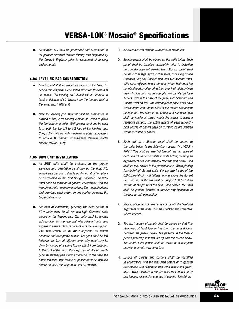
B. Foundation soil shall be proofrolled and compacted to
95 percent standard Proctor density and inspected by
the Owner’s Engineer prior to placement of leveling
pad materials.
4.04 LEVELING PAD CONSTRUCTION
A. Leveling pad shall be placed as shown on the final, P.E.
sealed retaining wall plans with a minimum thickness of
six inches. The leveling pad should extend laterally at
least a distance of six inches from the toe and heel of
the lower most SRW unit.
B. Granular leveling pad material shall be compacted to
provide a firm, level bearing surface on which to place
the first course of units. Well-graded sand can be used
to smooth the top 1/4-to 1/2-inch of the leveling pad.
Compaction will be with mechanical plate compactors
to achieve 95 percent of maximum standard Proctor
density (ASTM D 698).
4.05 SRW UNIT INSTALLATION
A. All SRW units shall be installed at the proper
elevation and orientation as shown on the final, P.E.
sealed wall plans and details on the construction plans
or as directed by the Wall Design Engineer. The SRW
units shall be installed in general accordance with the
manufacturer’s recommendations.The specifications
and drawings shall govern in any conflict between the
two requirements.
B. For ease of installation, generally the base course of
SRW units shall be all six-inch-high Standard units
placed on the leveling pad. The units shall be leveled
side-to-side, front-to-rear and with adjacent units, and
aligned to ensure intimate contact with the leveling pad.
The base course is the most important to ensure
accurate and acceptable results. No gaps shall be left
between the front of adjacent units. Alignment may be
done by means of a string line or offset from base line
to the back of the units. Placing panels of Mosaic direct-
ly on the leveling pad is also acceptable. In this case, the
entire ten-inch-high course of panels must be installed
before the level and alignment can be checked.
C. All excess debris shall be cleaned from top of units.
D. Mosaic panels shall be placed on the units below. Each
panel shall be installed completely prior to installing
horizontally adjacent panels. Each Mosaic panel shall
be ten inches high by 24 inches wide, consisting of one
Standard unit, one Cobble® unit, and two Accent ® units.
With each adjacent panel, the units at the bottom of the
panels should be alternated from four-inch-high units to
six-inch-high units. As an example, one panel shall have
Accent units at the base of the panel with Standard and
Cobble units on top. The next adjacent panel shall have
the Standard and Cobble units at the bottom and Accent
units on top. The order of the Cobble and Standard units
shall be randomly mixed within the panels to avoid a
repetitive pattern. The entire length of each ten-inch-
high course of panels shall be installed before starting
the next course of panels.
E. Each unit in a Mosaic panel shall be pinned to
the units below in the following manner: Two VERSA-
TUFF ® Pins shall be inserted through the pin holes of
each unit into receiving slots in units below, creating an
approximate 3/4-inch setback from the unit below. Pins
shall be fully seated in the pin slot below. When pinning
four-inch-high Accent units, the top two inches of the
6.8-inch-high pin will initially extend above the Accent
unit. The top of the pin shall be snapped-off by hitting
the top of the pin from the side. Once pinned, the units
shall be pushed forward to remove any looseness in
the unit-to-unit connection.
F. Prior to placement of next course of panels, the level and
alignment of the units shall be checked and corrected,
where needed.
G. The next course of panels shall be placed so that it is
staggered at least four inches from the vertical joints
between the panels below. The patterns in the Mosaic
panels generally shall not line up with the course below.
The bond of the panels shall be varied on subsequent
courses to create a random look.
H. Layout of curves and corners shall be installed
in accordance with the wall plan details or in general
accordance with SRW manufacturer’s installation guide-
lines. Walls meeting at corners shall be interlocked by
overlapping successive courses of panels. Special cor-
VERSA-LOK® Mosaic® Specifications
VERSA-LOK MOSAIC DESIGN AND INSTALLATION GUIDELINES 36

ner panels shall be installed such that both sides of the
corner panels vertically align the upper and lower units
to create ten-inch-high joints to butt against adjacent
regular Mosaic panels. For each course of panels, the
corner panels shall be installed first, then regular panels
installed out from the corners.
I. Procedures C. through G. shall be repeated until
reaching top of wall units, just below the height of the
cap units. Geosynthetic reinforcement, drainage
materials, and reinforced backfill shall be placed in
sequence with unit installation as described in Section
4.06, 4.07, and 4.08.
4.06 GEOSYNTHETIC REINFORCEMENT PLACEMENT
A. All geosynthetic reinforcement shall be installed at the
proper elevation and orientation as shown on the final,
P.E. sealed retaining wall plan profiles and details or as
directed by the Wall Design Engineer.
B. At the elevations shown on the final plans, (after the
units, drainage material, and backfill have been placed
to this elevation) the geosynthetic reinforcement shall be
laid horizontally on compacted infill and on top of the
concrete SRW units, to within one inch of the front face
of the unit below. Embedment of the geosynthetic in the
SRW units shall be consistent with SRW manufacturer’s
recommendations. Correct orientation of the geosyn-
thetic reinforcement shall be verified by the Contractor
to be in accordance with the geosynthetic manufactur-
er’s recommendations. The highest strength direction of
the geosynthetic must be perpendicular to the wall face.
C. Geosynthetic reinforcement layers shall be one continu-
ous piece for their entire embedment length. Splicing of
the geosynthetic in the design strength direction (per-
pendicular to the wall face) shall not be permitted. Along
the length of the wall, horizontally adjacent sections of
geosynthetic reinforcement shall be butted in a manner
to assure 100 percent coverage parallel to the wall face.
D. Tracked construction equipment shall not be operated
directly on the geosynthetic reinforcement. A minimum
of six inches of backfill is required prior to operation of
tracked vehicles over the geosynthetic. Turning should
be kept to a minimum. Rubber-tired equipment may
pass over the geosynthetic reinforcement at slow
speeds (less than 5 mph).
E. The geosynthetic reinforcement shall be free of
wrinkles prior to placement of soil fill. The nominal
tension shall be applied to the reinforcement and
secured in place with staples, stakes, or by hand
tensioning until reinforcement is covered by six inches
of fill.
4.07 DRAINAGE MATERIALS
A. Drainage aggregate shall be installed to the line, grades,
and sections shown on the final P.E. sealed retaining
wall plans. Drainage aggregate shall be placed to the
minimum thickness shown on the construction plans
between and behind units (a minimum of one cubic foot
for each exposed square foot of wall face unless
otherwise noted on the final wall plans).
B. Drainage collection pipes shall be installed to maintain
gravity flow of water outside the reinforced soil zone.
The drainage collection pipe shall daylight into a storm
sewer or along a slope, at an elevation lower than the
lowest point of the pipe within the aggregate drain.
4.08 BACKFILL PLACEMENT
A. The reinforced backfill shall be placed as shown in
the final wall plans in the maximum compacted lift
thickness of ten inches and shall be compacted to a
minimum of 95 percent of standard Proctor density
(ASTM D 698) at a moisture content within two percent
of optimum. The backfill shall be placed and spread in
such a manner as to eliminate wrinkles or movement of
the geosynthetic reinforcement and the SRW units.
B. Only hand-operated compaction equipment shall be
allowed within three feet of the back of the wall units.
Compaction within the three feet behind the wall
units shall be achieved by at least three passes of a
lightweight mechanical tamper, plate, or roller.
VERSA-LOK MOSAIC DESIGN AND INSTALLATION GUIDELINES37
VERSA-LOK® Mosaic® Specifications

C. At the end of each day’s operation, the Contractor shall slope
the last level of backfill away from the wall facing and rein-
forced backfill to direct water runoff away from the wall face.
D. At completion of wall construction, backfill shall be
placed level with final top of wall elevation. If final grad-
ing, paving, landscaping, and/or storm drainage installa-
tion adjacent to the wallis not placed immediately after
wall completion, temporary grading and drainage shall
be provided to ensure water runoff is not directed at the
wall nor allowed to collect or pond behind the wall until
final construction adjacent to the wall is completed.
4.09 SRW CAPS
A. SRW caps shall be properly aligned and glued
to underlying units with VERSA-LOK concrete adhesive,
a flexible, high-strength adhesive. Rigid adhesive or
mortar are not acceptable.
B. Caps shall overhang the top course of units by 3/4 to
one inch. Slight variation in overhang is allowed to cor-
rect alignment at the top of the wall.
4.10 CONSTRUCTION ADJACENT TO COMPLETED WALL
A. The Owner or Owner’s Representative is responsible for
ensuring that construction by others adjacent to the wall
does not disturb the wall or place temporary construc-
tion loads on the wall that exceed design loads, includ-
ing loads such as water pressure, temporary grades, or
equipment loading. Heavy paving or grading equipment
shall be kept a minimum of three feet behind the back
of the wall face. Equipment with wheel loads in excess
of 150 psf live load shall not be operated within ten feet
of the face of the retaining wall during construction
adjacent to the wall. Care should be taken by the
General Contractor to ensure water runoff is directed
away from the wall structure until final grading and sur-
face drainage collection systems are completed.
VERSA-LOK® Mosaic® Specifications
VERSA-LOK MOSAIC DESIGN AND INSTALLATION GUIDELINES 38

VERSA-LOK MOSAIC DESIGN AND INSTALLATION GUIDELINES39
VERSA-LOK® Mosaic®
Construction Details
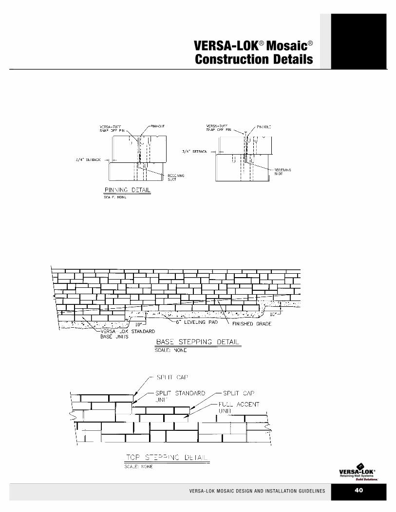
VERSA-LOK® Mosaic®
Construction Details
VERSA-LOK MOSAIC DESIGN AND INSTALLATION GUIDELINES 40

VERSA-LOK MOSAIC DESIGN AND INSTALLATION GUIDELINES41
VERSA-LOK® Mosaic®
Construction Details

VERSA-LOK® Mosaic®
Construction Details
VERSA-LOK MOSAIC DESIGN AND INSTALLATION GUIDELINES 42

A Division of Kiltie Corporation6348 Hwy 36, Suite 1Oakdale, MN 55128
(800) 770-4525(651) 770-3166 office(651) 770-4089 fax
www.versa-lok.com
Made worldwide under license from VERSA-LOK® Retaining Wall Systems.
U.S. Patent 6,488,448, U.S. Patent D319,885, U.S. Patent D321,060, U.S. Patent D341,215, U.S. Patent D346,667,
U.S. Patent D378,702, U.S. Patent D391,376, U.S. Patent D430,680, U.S. Patent D435,302, U.S. Patent D452,332
and other U.S. patents pending; Canadian Industrial Design Registration No. 63929, No. 71472, No. 73910,
No. 73911, No. 73912, No. 77816, No. 79058, No. 82288, and No. 89084.
© 2002 Kiltie Corporation • Printed in U.S.A. • VLM-602 • 20K • 12-02
THE INFORMATION, INCLUDING TECHNICAL AND ENGINEERING DATA, FIGURES, TABLES, DESIGNS, DRAWINGS, DETAILS, SUGGESTED PROCEDURES,
AND SUGGESTED SPECIFICATIONS, PRESENTED IN THIS PUBLICATION IS FOR GENERAL INFORMATION ONLY. WHILE EVERY EFFORT HAS BEEN MADE
TO ENSURE ITS ACCURACY, THIS INFORMATION SHOULD NOT BE USED OR RELIED UPON FOR ANY APPLICATION WITHOUT VERIFICATION OF
ACCURACY, SUITABILITY, AND APPLICABILITY FOR THE USE CONTEMPLATED, WHICH IS THE SOLE RESPONSIBILITY OF THE USER. A FINAL, PROJECT-
SPECIFIC DESIGN SHOULD BE PREPARED BY A QUALIFIED, LICENSED, PROFESSIONAL ENGINEER BASED ON ACTUAL SITE CONDITIONS. VERSA-LOK
RETAINING WALL SYSTEMS DISCLAIMS ANY AND ALL EXPRESS OR IMPLIED WARRANTIES OF MERCHANTABILITY FITNESS FOR ANY GENERAL OR
PARTICULAR PURPOSE, TRADEMARK, OR COPYRIGHT IN REGARD TO INFORMATION OR PRODUCTS CONTAINED OR REFERRED TO HEREIN.
Mosaic® Design & Installation GuidelinesMosaic® Design & Installation Guidelines