design guidelines - denvergov.org · u rban d esign s tandards andg uidelines c ommunity p lanning...
TRANSCRIPT
U R B A N D E S I G N S T A N D A R D S A N D G U I D E L I N E SC O M M U N I T Y P L A N N I N G A N D D E V E L O P M E N T A G E N C Y
C I T Y a n d C O U N T Y o f D E N V E R
D E C E M B E R 2 0 0 2C I T Y a n d C O U N T Y o f D E N V E R
D E C E M B E R 2 0 0 2
D E S I G N G U I D E L I N E Sf o r G O L D E N T R I A N G L E / B - 8 - G Z O N E D I S T R I C T
D E S I G N G U I D E L I N E Sf o r G O L D E N T R I A N G L E / B - 8 - G Z O N E D I S T R I C T
U R B A N D E S I G N S T A N D A R D S A N D G U I D E L I N E SC O M M U N I T Y P L A N N I N G A N D D E V E L O P M E N T A G E N C Y


CONTENTSI. Introduction . . . . . . . . . . . . . . . . . . . . . . . . . . . . . . . . . . 1
A. Context . . . . . . . . . . . . . . . . . . . . . . . . . . . . . . . . . . . . . . . . . . . . . . . . . . .2B. The Golden Triangle Neighborhood . . . . . . . . . . . . . . . . . . . . . . . . . . . .2C. Document Organization . . . . . . . . . . . . . . . . . . . . . . . . . . . . . . . . . . . . .4D. Terms . . . . . . . . . . . . . . . . . . . . . . . . . . . . . . . . . . . . . . . . . . . . . . . . . . . .4
1. Intent Statements . . . . . . . . . . . . . . . . . . . . . . . . . . . . . . . . . . . . . . . . . . .42. Design Standards . . . . . . . . . . . . . . . . . . . . . . . . . . . . . . . . . . . . . . . . . . .43. Design Guidelines . . . . . . . . . . . . . . . . . . . . . . . . . . . . . . . . . . . . . . . . . .4
E. Application of Design Criteria . . . . . . . . . . . . . . . . . . . . . . . . . . . . . . . . .5
II. Procedures. . . . . . . . . . . . . . . . . . . . . . . . . . . . . . . . . . . 9A. Design Review Process and Submittal Requirements . . . . . . . . . . . . . . .10
III. Design Review Criteria. . . . . . . . . . . . . . . . . . . . . . . . 12A. Site . . . . . . . . . . . . . . . . . . . . . . . . . . . . . . . . . . . . . . . . . . . . . . . . . . . . .13
1. Street grid . . . . . . . . . . . . . . . . . . . . . . . . . . . . . . . . . . . . . . . . . . . . . . .132. Access and site circulation . . . . . . . . . . . . . . . . . . . . . . . . . . . . . . . . . . . .133. Parking structures and lots . . . . . . . . . . . . . . . . . . . . . . . . . . . . . . . . . . . .144. Pedestrian connections and public spaces . . . . . . . . . . . . . . . . . . . . . . . . . .155. Building setbacks and build-to lines . . . . . . . . . . . . . . . . . . . . . . . . . . . . .15
a. General Locations . . . . . . . . . . . . . . . . . . . . . . . . . . . . . . . . . . . . . .16b. Civic Center . . . . . . . . . . . . . . . . . . . . . . . . . . . . . . . . . . . . . . . . . .16c. Speer Boulevard . . . . . . . . . . . . . . . . . . . . . . . . . . . . . . . . . . . . . . .18d. Colfax Avenue . . . . . . . . . . . . . . . . . . . . . . . . . . . . . . . . . . . . . . . .20e. Broadway-Lincoln . . . . . . . . . . . . . . . . . . . . . . . . . . . . . . . . . . . . . .20
B. Architecture . . . . . . . . . . . . . . . . . . . . . . . . . . . . . . . . . . . . . . . . . . . . . . .211. Form and massing . . . . . . . . . . . . . . . . . . . . . . . . . . . . . . . . . . . . . . . . .21
a. Building adjacencies . . . . . . . . . . . . . . . . . . . . . . . . . . . . . . . . . . . .21b. Relationship to street and public spaces . . . . . . . . . . . . . . . . . . . . . . . .21
1) Entries and corners . . . . . . . . . . . . . . . . . . . . . . . . . . . . . . . . .222) Orientation . . . . . . . . . . . . . . . . . . . . . . . . . . . . . . . . . . . . . .223) Ground floor uses . . . . . . . . . . . . . . . . . . . . . . . . . . . . . . . . .22
2. Building facades and roofs . . . . . . . . . . . . . . . . . . . . . . . . . . . . . . . . . . . .22a. Facades . . . . . . . . . . . . . . . . . . . . . . . . . . . . . . . . . . . . . . . . . . . . .22
1) Architectural scaling elements . . . . . . . . . . . . . . . . . . . . . . . . .232) Surface variation . . . . . . . . . . . . . . . . . . . . . . . . . . . . . . . . . .233) Windows . . . . . . . . . . . . . . . . . . . . . . . . . . . . . . . . . . . . . . . .24
a. Transparency . . . . . . . . . . . . . . . . . . . . . . . . . . . . . . . . . .24b. Window to Wall ratio . . . . . . . . . . . . . . . . . . . . . . . . . . . .24c. Detailing . . . . . . . . . . . . . . . . . . . . . . . . . . . . . . . . . . . .24
b. Roofs . . . . . . . . . . . . . . . . . . . . . . . . . . . . . . . . . . . . . . . . . . . . . . .25c. Materials . . . . . . . . . . . . . . . . . . . . . . . . . . . . . . . . . . . . . . . . . . . .25d. Building accessories and components . . . . . . . . . . . . . . . . . . . . . . . . .26
1) Balconies . . . . . . . . . . . . . . . . . . . . . . . . . . . . . . . . . . . . . . . .262) Porte cocheres and loading areas . . . . . . . . . . . . . . . . . . . . . . .263) Awnings and canopies . . . . . . . . . . . . . . . . . . . . . . . . . . . . . . .26
U R B A N D E S I G N S TA N D A R D S A N D G U I D E L I N E S
i

4) Building lighting . . . . . . . . . . . . . . . . . . . . . . . . . . . . . . . . . .265) Handicap ramps, stairs, elevators . . . . . . . . . . . . . . . . . . . . . . .276) Mechanical equipment . . . . . . . . . . . . . . . . . . . . . . . . . . . . . .277) Building security bars and fencing . . . . . . . . . . . . . . . . . . . . . .27
C. Landscape Architecture . . . . . . . . . . . . . . . . . . . . . . . . . . . . . . . . . . . . .271. Landscaping on private property . . . . . . . . . . . . . . . . . . . . . . . . . . . . . . . .27
a. Green space . . . . . . . . . . . . . . . . . . . . . . . . . . . . . . . . . . . . . . . . . .27b. Parking lot landscaping . . . . . . . . . . . . . . . . . . . . . . . . . . . . . . . . . .28c. Lighting . . . . . . . . . . . . . . . . . . . . . . . . . . . . . . . . . . . . . . . . . . . . .28
2. Public Right of Way and other public spaces . . . . . . . . . . . . . . . . . . . . . . .29a. Street trees and landscaping . . . . . . . . . . . . . . . . . . . . . . . . . . . . . . .29b. Pedestrian lighting and street lights . . . . . . . . . . . . . . . . . . . . . . . . . .29c. Sidewalks and pedestrian area paving . . . . . . . . . . . . . . . . . . . . . . . .30d. Street furniture and identity elements . . . . . . . . . . . . . . . . . . . . . . . .30e. General street design . . . . . . . . . . . . . . . . . . . . . . . . . . . . . . . . . . . .30
3. Fences, walls and railings . . . . . . . . . . . . . . . . . . . . . . . . . . . . . . . . . . . . .31a. Fences and walls on private property . . . . . . . . . . . . . . . . . . . . . . . . .31b. Railings in the public right of way . . . . . . . . . . . . . . . . . . . . . . . . . .31
IV. Design Review Premiums. . . . . . . . . . . . . . . . . . . . . . 32V. Sign Design Review . . . . . . . . . . . . . . . . . . . . . . . . . . 34
A. Location . . . . . . . . . . . . . . . . . . . . . . . . . . . . . . . . . . . . . . . . . . . . . . . . .35B. Style . . . . . . . . . . . . . . . . . . . . . . . . . . . . . . . . . . . . . . . . . . . . . . . . . . . .35C. Size . . . . . . . . . . . . . . . . . . . . . . . . . . . . . . . . . . . . . . . . . . . . . . . . . . . . .36
VI. Public Art Premiums . . . . . . . . . . . . . . . . . . . . . . . . . 37A. Qualifications . . . . . . . . . . . . . . . . . . . . . . . . . . . . . . . . . . . . . . . . . . . . .38B. Art Approval . . . . . . . . . . . . . . . . . . . . . . . . . . . . . . . . . . . . . . . . . . . . .38C. Design and Concept Requirements . . . . . . . . . . . . . . . . . . . . . . . . . . . .38
1. Location . . . . . . . . . . . . . . . . . . . . . . . . . . . . . . . . . . . . . . . . . . . . . . . .382. Art Types . . . . . . . . . . . . . . . . . . . . . . . . . . . . . . . . . . . . . . . . . . . . . . . .393. Review Criteria . . . . . . . . . . . . . . . . . . . . . . . . . . . . . . . . . . . . . . . . . . .39
VII. Glossary of Terms and Abbreviations . . . . . . . . . . . 40VIII. Approvals and Signatures . . . . . . . . . . . . . . . . . . . . 42IX. Appendices . . . . . . . . . . . . . . . . . . . . . . . . . . . . . . . . 43
Acknowledgements . . . . . . . . . . . . . . . . . . . . . . . . . . . . . . . . . . . . . . . . . . . . .44Civic Center Building Height Restrictions &State Capitol View Plane Height Restrictions . . . . . . . . . . . . . . . . . . . . . . . . . . . . .46Streetscape Requirements . . . . . . . . . . . . . . . . . . . . . . . . . . . . . . . . . . . . . . . .48Broadway/Lincoln Streetscape Template . . . . . . . . . . . . . . . . . . . . . . . . . . . . . . .49Street Lighting Specifications . . . . . . . . . . . . . . . . . . . . . . . . . . . . . . . . . . . . . .50B-8-G Design Review Application Form . . . . . . . . . . . . . . . . . . . . . . . . . . . . . .54
G O L D E N T R I A N G L E – B - 8 - G
ii
INTRODUCTION
U R B A N D E S I G N S TA N D A R D S A N D G U I D E L I N E S
1

A. CONTEXT
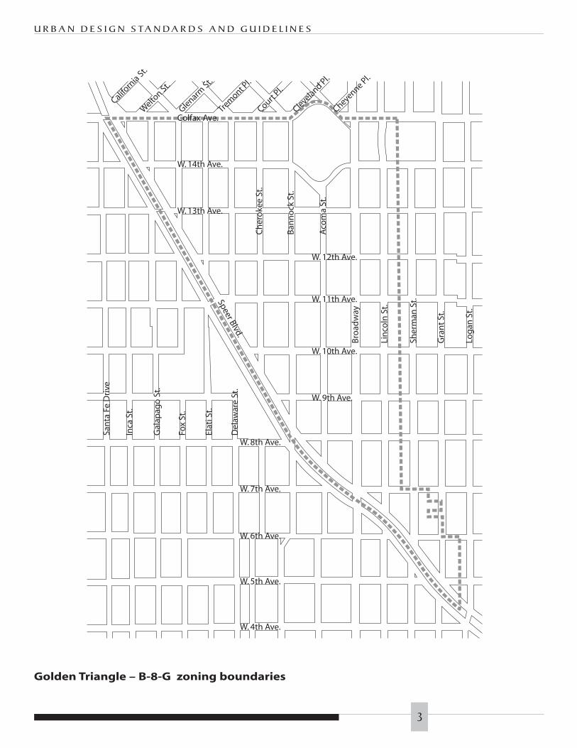
Land use and design in Denver’s GoldenTriangle neighborhood are regulated by theB-8-G zone district and guided by theGolden Triangle Neighborhood Plan. Thezone district mandates that the design ofall new projects and significant renovationof existing buildings be approved by theCommunity Planning and DevelopmentAgency (CPDA). The Denver PlanningBoard adopted the design procedures andcriteria as rules and regulations for CPDA.
The design criteria address the quality ofthe urban environment, recognizing that itis ultimately formed by countlessindividual creative decisions. Thestandards and guidelines are intended topresent design principles that encouragedevelopment that promotes cohesivenessand compatibility with the existing anddesired character of the area, as well asexcellence in urban design. They are notintended to restrict innovation,imagination or variety in design. If analternative design can be demonstrated toachieve the desired character better thanthe general criteria, the Urban Design staffmay consider a substitution.
The design criteria implement the B-8-Gdesign review procedure (RMC Section 59-399.9) and are based on the fundamentalobjectives contained in the zoningordinance:
◗ To be consistent with the urban designgoals of the Denver comprehensiveplan, including the Golden TriangleNeighborhood Plan;
◗ To provide human scale throughchange, contrast and intricacy in façadeform, color and/or materials;
◗ To spatially define the street spaces andopen spaces in order to promote theimage of a cohesive, identifiable,pedestrian-oriented neighborhood;
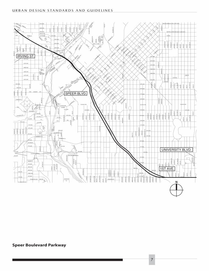
◗ To respect the parkway character ofSpeer Boulevard as it passes throughthe neighborhood; and
◗ To respect the civic character of theCivic Center area.
The criteria are also consistent with themore specific design goals articulated inDenver Comprehensive Plan 2000, BlueprintDenver: An Integrated Land Use andTransportation Plan and the GoldenTriangle Neighborhood Plan.
These design standards and guidelines alsoreference other review criteria anddocuments, including:
◗ PUD/PBG Site Plan Rules andRegulations, including designregulations for development alongdesignated Commercial Corridors
◗ Rules and Regulations for theLandscaping of Parking Areas, 1991
◗ Civic Center Design Guidelines, 1996
◗ Design Guidelines for LandmarkStructures and Districts, 1995
B. THE GOLDEN TRIANGLEB. NEIGHBORHOOD
The City and County of Denver adoptedthe Golden Triangle Neighborhood Plan in1998. That plan set forth a vision of theneighborhood as a community with amixture of housing, office, commercial,destination and neighborhood-servingretail; a walkable neighborhood with activepedestrian-oriented public uses on theground floors of mixed-use projects,generous sidewalks, enhancedstreetscaping, and building design withhuman scale and detail. Preservation of
G O L D E N T R I A N G L E – B - 8 - G
2
Colfax Ave.Court
Pl.
Trem
ont Pl.
Glenarm St.
Welto
n St.
Californ
ia St.
Cleveland Pl.
Cheyenne Pl.
W. 14th Ave.
W. 13th Ave.
W. 12th Ave.
Speer Blvd.
W. 11th Ave.
W. 10th Ave.
W. 9th Ave.
W. 8th Ave.
W. 7th Ave.
W. 6th Ave.
W. 5th Ave.
W. 4th Ave.
Bro
adw
ay
Lin
coln
St.
Sher
man
St.
Aco
ma
St.
Ban
no
ck S
t.
Ch
ero
kee
St.
Del
awar
e St
.
Elat
i St.
Fox
St.
Gal
apag
o S
t.
Inca
St.
San
ta F
e D
rive
Gra
nt
St.
Log
an S
t.
U R B A N D E S I G N S TA N D A R D S A N D G U I D E L I N E S
3
Golden Triangle – B-8-G zoning boundaries

historically significant buildings and designof contemporary structures is key tocreating a unique character and sense ofplace for the Golden Triangle. The GoldenTriangle is envisioned as an eclecticneighborhood where no specificarchitectural style is intended. However, allprojects should be responsive to context,influenced by adjacent buildings’ scale andarchitectural character.
C. DOCUMENT ORGANIZATION
There are two sections to the GoldenTriangle Design Review Criteria document:procedures for design review and designcriteria for evaluating proposeddevelopment projects.
The review procedures are intended to beclear and precise, yet flexible enough tosatisfy project-development schedules anddesign intentions. The applicant ordesigner using this document should befamiliar with the procedures for designreview before referring to the standards andguidelines in this document.
D. TERMS
The design criteria are the objectives andrequirements for design of new projectsand are listed under three headings foreach review category: Intent, Standards and Guidelines.
1. Intent Statements
Intent statements define the goals whichthe design review criteria have beencreated to achieve. In circumstanceswhere the standard or guideline is inquestion or under negotiation, the intentstatement will serve to provide additionaldirection to the Urban Design staff andthe design team.
2. Design Standards
Design standards are criteria that providespecific direction based on the statedintent. Standards are used to denoteissues that are considered fundamental toachieving the stated intent. Standardsprovide the basic design foundation thatis expected of every project.
Standards use the term “shall” to indicatethat compliance is required by all projects.Some standards are based on requirementsof the Zoning Code and cannot be waivedthrough the Design Review procedure.Other standards are based on designprinciples separate from zoning coderegulations and may be waived in exchangefor better achievement of the stated intentand overall improvement to the design.The Urban Design staff may find cause tomodify one or more standards if theapplicant demonstrates that one or moreof the following conditions exists:
◗ The alternative, such as expressed inthe Guidelines, better achieves thestated intent;
◗ The intent which the standard wascreated to address will not be achievedby application of the standard in aparticular circumstance;
◗ The application of other standards andguidelines to achieve the stated intentwill be improved by not applying astandard; or
◗ Unique site factors make the standardimpractical or cost prohibitive.
3. Design Guidelines
Design guidelines are designconsiderations that promote the goalsdefined by the intent statements.Guidelines allow more flexibility thandesign standards for projects that intend tomeet the design goals by means other than
G O L D E N T R I A N G L E – B - 8 - G
4

the basic standards. Complying with someor all of the guidelines may act as asubstitute for the standards in somecircumstances when used in conjunctionwith the intent statements. Designapprovals based on use of the guidelinesmust result in an improved design thatbenefits the district as well as theindividual project. Design approvals basedon the guidelines, rather than standards,require more discussion and negotiationbetween the City staff and thedevelopment team.
E. APPLICATION OFDESIGN CRITERIA
As authorized by RMC 59-399.9, designreview under these design standards andguidelines is mandatory for:
1. Project layout and design of the lowereighty feet (80’) of facades that face apublic street of:
a. All structures constructed in the B-8-G zone district;
b. The renovation of existing structureswhere the renovation is valued atmore than fifty-percent (50%) ofthe replacement cost, excludingland costs, and the renovationincludes alterations to the exteriorof the structure.
2. Project layout and design of the entirefaçade of buildings on lots contiguouswith Speer Boulevard, as outlined inRMC 59-399.4(a)(3).
3. Projects that apply for a density bonusin exchange for design review of theentire structure, as outlined in RMC59-399.4(b)(3).
4. Projects that apply for floor areapremium for public art, as outlined inRMC 59-399.4(b)(2)(f).
The design review procedures and criteriado not apply to structures that are reviewedunder other City design review ordinances,including overlay districts and HistoricLandmark structures and districts.
Other jurisdictional overlaps include:
1. Denver Department of Public Worksmanages and regulates the public rightof way.
2. Denver Landmark PreservationCommission has design reviewauthority over buildings located inHistoric Landmark Districts andbuildings designated as DenverLandmark Preservation structures. LPCalso has design review authority overany changes to the Speer BoulevardHistoric Parkway right of way. LPCmay be provided an opportunity for acourtesy (non-binding) review of allprojects on properties adjoiningHistoric Districts.
3. Denver Department of Parks andRecreation coordinates changes tothe Speer Boulevard right of way withthe Denver Landmark PreservationCommission and the Department ofPublic Works. DPR also sharesjurisdiction over development alongdesignated parkways, includingSpeer Boulevard, and a segment of14th Avenue.
4. Denver Community Planning andDevelopment Agency coordinates andapproves all planned developmentsand planned building groups.
U R B A N D E S I G N S TA N D A R D S A N D G U I D E L I N E S
5

GR
AN
T S
T.
SH
ER
MA
N S
T.
16TH AVE.C
HE
RO
KE
E S
T.
BA
NN
OC
K S
T.
BR
OA
DW
AY
14TH AVE.
15TH ST.
16TH ST.
14TH ST.
GLENARM
PL.
TREMONT P
L.
COURT PL.
CLEVELA
ND PL.
COLFAX AVE
13TH ST.
DE
LAW
AR
E S
T.
CHEYENNE PL.
12TH AVE.
AC
OM
A S
T.
LIN
CO
LN S
T.
N
G O L D E N T R I A N G L E – B - 8 - G
6
Civic Center Landmark District
I - 25
MARKET S
T.
BLAKE S
T.
AURARIA
PARKWAY
MARKET S
T.
BLAKE S
T.
WALN
UT ST.
WALNUTST.
FE
DE
RA
L B
LVD
.
VIADUCT
FE
DE
RA
L B
LVD
.F
ED
ER
AL
BLV
D.
COLFAX AVE.COLFAX AVE.
6TH AVE.
COLFAX AVE.
MARTIN LUTHER KING BLVD. (32ND AVE.)
ST.
PARKWAY
YO
RK
ST
.Y
OR
K S
T.
14TH AVE.
31st Ave.
23RD AVE.
DO
WN
ING
ST
.
PARK AVE WEST
WELT
ON ST.
BR
OA
DW
AY
LAW
RENCE ST.
LARIM
ER ST.
ARAPAHOE ST.
CURTIS S
T.
CALIFORNIA
ST.
STOUT ST.
CHAMPA S
T.
20TH AVE.
DO
WN
ING
ST
.
CO
RO
NA
ST
.
19TH AVE.
18TH AVE.
17TH AVE.
14TH AVE.
13TH AVE.
LIN
CO
LN S
T.
6TH AVE.
8TH AVE.
LOG
AN
ST
.
WA
SH
ING
TO
N S
T.
BR
OA
DW
AY
CLA
RK
SO
N S
T.
20TH AVE.
FO
X S
T.
19TH ST.18TH ST.
20TH ST.
ST.
17TH ST.
16TH
ARAPAHOE ST.
PE
CO
S S
T.
OS
AG
E S
T.
WAZEE S
T.
SPEER BLVD
.
15TH ST.
TREMONT P
L.
GLENARM
PL.
WELT
ON ST.
15TH ST.14TH ST.
BLV
D.
13TH ST.
MALL
STOUT ST.
CALIFORNIA
ST.
SPEER BLVD
.
SA
NT
A F
E D
R.
14TH AVE.
7TH
ST.
6TH AVE.
KA
LAM
AT
H S
T.
SP
EE
R
LARIM
ER ST.
14TH C
T.
CURTIS S
T.
LAW
RENCE ST.
CHAMPA S
T.
COURT ST.
1ST AVE.
UN
IVE
RS
ITY
BLV
D.
EM
ER
SO
N S
T.
DO
WN
ING
ST
.
WA
SH
ING
TO
N S
T.
BR
OA
DW
AY
LIN
CO
LN S
T.
SA
NT
A F
E D
R.
KA
LAM
AT
H S
T.
6TH AVE. SERVICE RD.
ZU
NI S
T.
TE
JON
ST
.
29TH AVE.
ZU
NI S
T.
SPEER BLVD.
26TH AVE.
(LOWER)
26TH AVE.
FR
AN
KLI
N S
T.
FR
AN
KLI
N S
T.
CHEYENNE PL.
7TH AVE.
11TH AVE.
12TH AVE.
DELGANY S
T.
DE
NA
RG
O S
T.
ST.ST.BOULD
ER
PLATTECENTRAL
GA
LAP
AG
O
BA
NN
OC
K S
T.
CH
ER
OK
EE
ST
.
13TH AVE.
CURTIS ST.
MA
RIP
OS
A S
T.
CLEVELA
ND PL.
BRUCE RANDOLPH AVE. (34TH AVE.)
1ST AVE.BA
NN
OC
K S
T.
OS
AG
E S
T.
32ND AVE.
33RD AVE.
WATER ST.
FRONTVIEWCRESCENT DR.
CLA
Y S
T.
23RD AVE.
IRV
ING
ST
.
UM
AT
ILLA
ST
.
ZU
NI S
T.
BR
YA
NT
ST
.
13TH AVE.
RD.
AVE.
YU
MA
WY
AN
DO
T S
T.
ST
.
AVE.
DICK
IRV
ING
ST
.
14TH
DE
CA
TU
R S
T.
HOWARD PL.
MO
RRISO
N
CONNOR
20TH AVE. CLA
Y S
T.
2ND AVE.
1ST AVE.
WALNUT ST.
COLFAX AVE.
HIG
H S
T.
VIN
E S
T.
PARK PL.
GA
YLO
RD
ST
.
RA
CE
ST
.
GA
YLO
RD
ST
.
HIG
H S
T.
RA
CE
ST
.
VIN
E S
T.
HIG
H S
T.
GA
YLO
RD
ST
.
VIN
E S
T.
RA
CE
ST
.
31ST ST.
32ND ST.
33RD ST.
LAF
AY
ET
TE
ST
.
HU
MB
OLD
T S
T.M
AR
ION
ST
.
22ND AVE.
25TH AVE.
24TH AVE.
GLENARM
PL.
LAF
AY
ET
TE
ST
.
HU
MB
OLD
T S
T.
FR
AN
KLI
N S
T.
GIL
PIN
ST
.
WIL
LIA
MS
ST
.
MA
RIO
N S
T.
29TH ST.
27TH ST.
COURT ST.
GLENARM
PL.
TREMONT P
L.
ST.
25TH
22ND ST.
24TH ST.
26TH ST.
28TH ST.
30TH ST.
GIL
PIN
ST
.
WIL
LIA
MS
ST
.
GIL
PIN
ST
.
OG
DE
N S
T.
DO
WN
ING
ST
.
MA
RIO
N S
T.
HU
MB
OLD
T S
T.
LAF
AY
ET
TE
ST
.
OG
DE
N S
T.
EM
ER
SO
N S
T.
MA
RIO
N S
T.
16TH AVE.
10TH AVE.
9TH AVE.
PE
AR
L S
T.
PE
NN
SY
LVA
NIA
ST
.
GR
AN
T S
T.
SH
ER
MA
N S
T.
EM
ER
SO
N S
T.
ST
.
30TH
31ST
GA
LAP
AG
O S
T.
INC
A S
T.
HU
RO
N S
T.
AVE.
AVE.
ST.
DELGANY
WYNKOOP S
T.
FO
X
AVE.29TH
NA
VA
JO S
T.
KA
LAM
AT
H S
T.
ST.
18TH ST.17TH
KENSINGCT.
ST.
SH
OS
HO
NE
ST
.
QU
IVA
S S
T.
19TH ST.
BASS
ET S
T.
ST.
12TH
WEW
ATTA ST.
ST.
GR
INN
ELL
CT.
11TH
BASSET ST.
LITTLE
R
AVEN ST.
CH
ESTN
UT
PL.
SA
NT
A F
E D
R.
RO
CKM
ON
T
DR
IVE
FO
X S
T.
ST
.
DE
LEW
AR
E S
T.
AC
OM
A S
T.
ELA
TI S
T.
ST.
ST.
RIO
CT
.
5TH S
T.
14TH AVE.
QU
IVA
S S
T.
AVE. ST
.
SE
MIN
OLE
RD
.
LIP
AN
ST
.
SH
OS
HO
NE
ST
.
OS
AG
E S
T.
PE
CO
S
9TH
21ST ST.
21ST AVE.
WIL
LIA
MS
ST
.
HIG
H S
T.
HIG
H S
T.
RA
CE
ST
.
VIN
E S
T.
GA
YLO
RD
ST
.
CIR
CLE
DR
.
FR
AN
KLI
N S
T.
GIL
PIN
ST
.
FR
AN
KLI
N S
T.
GIL
PIN
ST
.
LAF
AY
ET
TE
ST
.
HU
MB
OLD
T S
T.
3RD AVE.
OG
DE
N S
T.
CO
RO
NA
ST
.
MA
RIO
N S
T.
5TH AVE.
4TH AVE.
PE
AR
L S
T.
2ND AVE.
PE
NN
SY
LVA
NIA
ST
.
CLA
RK
SO
N S
T.
SPEER BLVD.
SH
ER
MA
N S
T.
GR
AN
T S
T.
LOG
AN
ST
.
3RD AVE.
IRVINGTON PL.
DE
LEW
AR
E S
T.
CH
ER
OK
EE
ST
.
AC
OM
A S
T.
INC
A S
T.
GA
LAP
AG
O S
T.
FO
X S
T.
ELA
TI S
T.
LIP
AN
ST
.
MA
RIP
OS
A S
T.
QU
IVA
S S
T.
PL.
IRVINGTON
RIO
GR
AND
E CT.
WIL
LIA
MS
ST
.
RA
RIT
AN
WA
Y
31ST AVE.
30TH AVE.
VA
LLE
JO S
T.
WY
AN
DO
T S
T.
CAITHNESS
DUNKELD
PL.
FIF
EC
T.
34TH AVE.
ARGYLE PL.
PL.
28TH AVE.
7TH S
T.MUSEUM DR.
CHILDRENS
FIRTH
CT.
RIVERDR.
BR
YA
NT
ST
.
ALC
OT
T S
T.
DOUGLASPL.
PARK PL.
PL.
AVE.
GROVE ST.
GREEN CT.
HIGHLANDFAIRVIEW
GR
OV
ES
T.
ELI
OT
ST
.
DE
CA
TU
R S
T.
24TH AVE.
22ND AVE.
21ST AVE.
25TH AVE.
DE
CA
TU
R S
T.
HA
ZE
L C
T.
HO
OK
ER
ST
.S
T.
WAZEE
12TH PL.
PL.
MYRTLE
CT
.
CA
NO
SA
12TH
10TH AVE.
MULBERRY PL.
ST
.
VA
LLE
JO
ST
.
UM
AT
ILLA
TE
JON
ST
.
XIN
CA
ST
.
PL.
12TH AVE.
ST
.
CA
NO
SA
CT
.
BARBERRY PL.
WAY
CLAY
ALC
OT
T
ELI
OT
ST
.
ELI
OT
ST
.
GR
OV
E S
T.
HO
OK
ER
ST
.
AVONDALE DR.
CONEJOS PL.
11TH AVE.
10TH AVE.
9TH AVE.
8TH AVE.
SEVERN PL.
7TH AVE.
GR
OV
E S
T.
IRV
ING
ST
.
HA
ZE
L S
T.
HO
OK
ER
ST
.
12TH AVE.
HOLDEN
COLFAX AVE.
19TH AVE.
18TH AVE.
5TH AVE.
VA
LLE
JO S
T.
YU
MA
ST
.
WY
AN
DO
T S
T.
BR
YA
NT
ST
.
BRYANT WA
Y
SHORT PL.
4TH AVE.
3RD AVE.
PARK AVE.
1ST AVE.
5TH AVE.
IRVINGTON AVE.
ELLSWORTH AVE.
2ND AVE.
ERIE S
T.
7TH AVE.
BARBERRY PL.
SPEER BLVD.
IRVING ST.
1ST AVE.
UNIVERSITY BLVD.
N
U R B A N D E S I G N S TA N D A R D S A N D G U I D E L I N E S
7
Speer Boulevard Parkway

12TH AVE.
11TH AVE.
10TH AVE.
9TH AVE.
BR
OA
DW
AY
LIN
CO
LN S
T.
SH
ER
MA
N S
T.
GR
AN
T S
T.
LOG
AN
ST.
N
G O L D E N T R I A N G L E – B - 8 - G
8
Sherman-Grant Historic District
PROCEDURES
U R B A N D E S I G N S TA N D A R D S A N D G U I D E L I N E S
9

G O L D E N T R I A N G L E – B - 8 - G
10
Design review will be conducted by theUrban Design section of the CommunityPlanning and Development Agency underthe direction of the Director of CPDA orthe Director’s designee.
A. SUBMITTAL REQUIREMENTS
Preapplication Conference: A mandatorymeeting shall be held between theapplicant and appropriate urban design,planning and zoning staff to review thescope of the project and to inform theapplicant of relevant city plans, policies,regulations, review processes andprocedures, and to provide a list ofrelevant registered neighborhoodorganizations (RNOs). Applicants areencouraged to meet with CPDA staff earlyin the planning process.
Neighborhood Presentation: No less than30 days prior to submitting the designreview application to the ZoningAdministrator, the applicant shall contactand, if requested, present proposed projectto the RNOs. In the event of requests frommultiple neighborhood organizations, ajoint meeting may be held.
Optional Schematic Conference:Applicant may meet with CPDA staff toreview the schematic design and site planin order to receive comments and toidentify issues.
Design Review Application andSubmittals: The applicant shall submit acomplete Design Review applicationpacket to Zoning Administration, whichshall forward the packet to the UrbanDesign section of CPDA. The applicantshall provide duplicate submittals thatthe Urban Design Section shall forwardto RNOs whose boundaries include the
subject property within five days ofreceipt. Sufficient information and detailmust be provided to fully evaluaterelevant issues.
A complete application shall include:
◗ Completed application form, a pointby point narrative description of howthe proposed project meets the designcriteria (standards, guidelines or othermeans of meeting the design intentstatements), intent to utilize floor areapremiums (if applicable), requests forspecial considerations such as phasedapprovals, and proof of neighborhoodnotification and presentation;
◗ Project program, parking provisions,area and FAR calculations;
◗ Drawings describing the projectelements subject to design review,including but not limited to:
◗ Site and context plan, includingproposed setbacks;
◗ Ground floor plan, showing allentrances;
◗ All other floor plans as necessaryto describe typical massing;
◗ All building elevations andarchitectural façade details, in color renditions;
◗ Landscape plan;
◗ Photographs of street-facingfacades of existing buildingsadjoining and across from theproposed project;
◗ Building materials and description;
◗ Colored elevation renderings ifrequested; and
◗ Other information as requested.

Design Review: Urban Design staff shallreview the submittal for conformance withthe B-8-G Design Criteria, DenverComprehensive Plan (including adoptedneighborhood plans), relevant Citypolicies, rules and regulations. Writtencomments received by the Urban DesignSection from RNOs within 15 days ofnotification by the Urban Design Sectionwill be considered. Urban Design shallapprove, approve with conditions, or denythe application. The Design Reviewdecision shall be forwarded to the ZoningAdministrator and to the applicant.
Schedule: A Design Review decision willbe rendered in no more than 30 calendardays after the submission of a completeapplication to the Zoning Administrator,or the design shall be consideredapproved. An interim meeting may beheld to review the proposed project and toprovide preliminary comments within the30-day period. The time for review may beextended by mutual consent. The ZoningAdministrator shall not issue permits foruse and construction until the UrbanDesign section of CPDA certifies thatdesign review has been completed and theconditions have been met, or until thereview period, as it may have beenextended, has elapsed.
Approval Expiration: Design approvals ateach project phase will be valid for aperiod of three years, unless the nature ofthe approved phase of the overall projectsignificantly changes. The applicant mayrequest an extension of the approvalperiod without additional design review,provided the originally approved projecthas not been changed.
Compliance Confirmation: Zoning andUrban Design staff will confirm thatConstruction Documents are consistentwith design approvals prior to issuingzoning permits. Any proposed changes tothe approved building design must beresubmitted for review.
Appeals Process: Appeals by any aggrievedparty will be heard by the Denver Board ofAdjustment for Zoning Appeals followingthe Board’s rules for public hearings.Appeals must specify the grounds uponwhich the relief is claimed and must befiled within 15 days of the action that isbeing appealed.
U R B A N D E S I G N S TA N D A R D S A N D G U I D E L I N E S
11

G O L D E N T R I A N G L E – B - 8 - G
12
DESIGN REVIEW CRITERIA

U R B A N D E S I G N S TA N D A R D S A N D G U I D E L I N E S
13
The Design Standards and Guidelines arestructured around five major areas ofconsideration in the analysis of the urbandesign qualities of a public or privatedevelopment: Site, Architecture,Landscape Architecture, Public Art, andSign Design Review.
A. SITE 1. STREET GRID
INTENT
◗ To maintain the grid patterns of streets,blocks and alleys to reinforce theexisting urban structure.
◗ To maximize uninterrupted pedestrianaccess to enhance and maintain thepedestrian–oriented character of theneighborhood.
◗ To enhance the variety and interest ofthe street environment for pedestrians.
◗ To retain essential scale and patternof development resulting fromtraditional street and alley gridestablished by a public alley.
STANDARDS
◗ Public street shall remain open topedestrian and vehicular access.
◗ Pedestrian access shall be maintainedalong street grid system.
◗ Minimize the number of curb cuts onthe street.
◗ Alley vacations shall not be allowedexcept in limited circumstances, suchas on non-standard blocks or insituations as outlined in the Guidelinesand the Speer Boulevard Sub-Area.
◗ Implement the Golden Triangleneighborhood streetscape plan.
GUIDELINES
◗ Multiple access choices provided by theDenver street and alley grid systemshould be maintained.
◗ Avoid closing portions of the grid.
◗ Avoid displacing traffic load from onestreet to another.
◗ Alley vacations may be approved if theproposed project clearly demonstratesachievement of the intent statements,and if the alley vacation results inincreased pedestrian and vehicularsafety, a more logical development,and the development reflects the scaleand massing typically established bythe alley.
◗ Use of the public right of way may beallowed if the proposed encroachmentenhances the street environment.
2. ACCESS AND SITECIRCULATION
Note: All vehicular access shall beapproved by Department of PublicWorks/Transportation Engineering. TheDepartment of Parks and Recreation shallalso review vehicular access on Speer Blvd.
INTENT
◗ To maximize uninterrupted pedestrianaccess within a given block to enhanceand maintain the desired character ofthe district as a walkableneighborhood.
◗ To minimize the visual presence ofauto circulation, as well as servicefunctions such as deliveries andrefuse pickup.
◗ To minimize the presence of auto-related functions visible from thestreet, and between the primarybuildings and the street.
◗ To minimize the number of curbcuts and access points on a block orstreet frontage.
STANDARDS
◗ The Department of Public Worksgenerally grants one access per project.

If more than one access is necessary forthe safe and efficient movement oftraffic as established by the TrafficImpact Study, the City may grantadditional access on a case-by-case basis.
◗ Porte-cochere type entries, drop-offsor drives shall not be parallel to thestreet/sidewalk.
◗ Garage doors and gates shall be setback from the ROW to avoid vehiclesblocking the sidewalk (usually aminimum of tenty feet [20’]).Architectural scaling elements shall beused to minimize apparent size ofgarage doors.
◗ All service functions shall beaccommodated off the alley or interiorto the building.
◗ Vehicular uses, including parking, shallnot be located in the front setback, orbetween the primary building and thestreet ROW. Service functions shall notbe visible from the street ROW.
GUIDELINES
◗ Developments should provide siteaccess for vehicles via alleys and avoidor minimize curb cuts.
◗ Driveways should be oriented 90degrees to the street. Porte-cocheresmay be accepted if they are located at90 degrees to the street.
◗ Driveways visible from the publicROW should incorporate surfacepatterns that provide scale, texture andvariety. Right of way concrete shouldbe plain and uncolored.
◗ City-designated passenger curbsideloading zones in the right of way areacceptable, provided the loading zonesdo not erode or interrupt the tree lawn.
◗ Shared drives are encouraged.
3. PARKING STRUCTURES AND LOTS
INTENT
◗ To create a walkable neighborhood byproviding active pedestrian-orientedpublic uses on street-facing groundfloors of parking structures.
◗ To minimize the visual impact ofparking structures and parking lots onthe streetscape and the impact ofvehicle noise, headlights, lighting andmechanical systems associated withparking facilities.
STANDARDS
◗ Street-facing ground floor levels shallhave pedestrian active uses such asretail, office, studios or residentialunits (see glossary). Lighting andmechanical systems associated withparking facilities shall be screened andlocated to avoid adverse impacts toother uses. Screening elements shallbe architecturally compatible withdominant building(s) in terms ofmaterial quality and detail.
◗ Surface parking lots shall be located tothe side or rear of buildings.
GUIDELINES
◗ Parking structures should incorporateground floor retail, office, studios orresidential units along street frontages.Street-level pedestrian active uses atgarage facades may be waived,provided future conversion to retailand commercial uses isaccommodated in the design of thestructure. Accommodation requireson-grade access, floor to floorclearances, utility layouts, and baydepths which would readily facilitateconversion of these spaces intocommercial uses. Garage facadeswithout immediate pedestrian active
G O L D E N T R I A N G L E – B - 8 - G
14
Masonry walls and landscaping
screen this dumpster.

uses must incorporate architecturalscaling elements as described under“Building Facades and Roofs”.
◗ Parking facility setbacks should notdisrupt the street wall.
◗ Lighting and mechanical systemsassociated with parking facilitiesshould not impact adjacent properties.
4. PEDESTRIAN CONNECTIONSAND PUBLIC SPACES
INTENT
◗ To give prominence to the pedestrianrealm as a major element ofneighborhood character.
◗ To create opportunities for informalinteraction within the Triangle andconvenient use of surrounding publicamenities through enhancedpedestrian connections.
◗ To provide community open spacewithin the neighborhood; createinformal gathering places.
◗ To encourage opportunities forpedestrian connections in addition toROW improvements.
STANDARDS
◗ Unobstructed walkway in the ROWshall be provided throughout thedistrict. The minimum equirements areeither five foot (5’) detached with eithfoot (8’) tree lawn, or ten foot (10’)detached with five foot (5’) amenityzone. See appendix for locations.
◗ Maintain and re-lay historic stonesidewalks in the ROW.
◗ Pedestrian circulation shall beprovided for all major areas of the siteand connections to the public ROW.
◗ All primary entries as well as groundfloor street-facing uses shall providedirect street access.
GUIDELINES
◗ Maximize visibility and animationalong pedestrian pathways by orientingwindows, secondary entries andbalconies towards walks.
◗ Pedestrian amenities such as benches,bike racks, and trash receptacles shouldbe placed to encourage pedestrianactivity with open visibility and accessfrom the public sidewalk.
◗ Businesses should utilize existingsetbacks with outdoor cafes & seating,displays, and local art.
◗ Supplemental plantings and seatingareas should be provided at recessedentrances.
5. BUILDING SETBACKS ANDBUILD-TO LINES
INTENT
◗ To enhance the urban character of theneighborhood by placement ofprimary structures to provide aconsistent edge to the street.
◗ To promote the development ofbuildings that incorporate pedestrianactivity through the inclusion ofpedestrian-oriented uses at the groundlevel street frontage.
U R B A N D E S I G N S TA N D A R D S A N D G U I D E L I N E S
15
The Police Administration building at Cherokee and West 14th Avenue is an example of a drive
aisle parallel to the public street. This condition disrupts pedestrian movement and shall not be used
in new development.

City and County Building, Civic
Center Sub-Area
Speer Boulevard streetscape
G O L D E N T R I A N G L E – B - 8 - G
16
Recently developed informal open
space (Cherokee & Speer)
Continuous street wall (Delaware
& 13th Ave.)
◗ To enhance the unique characteristicsof the Golden Triangle’s sub-areas,including Civic Center,Lincoln/Broadway, Speer Boulevard,Colfax Avenue, Acoma Street and theinterior of the neighborhood.
a. General Locations
INTENT
◗ To reinforce the a consistent streetwall inclose proximity to the public right of way.
STANDARDS
◗ Buildings shall be located at or withinfive feet (5’) of the property lineadjoining the street for no less thansixty-five percent (65%) of each zonelot frontage unless otherwise specifiedin specific subarea standards andguidelines. When the building is anaddition to an existing structure, streetedge shall be determined by the totalbuilding frontage (original structureplus the addition).
◗ Sites with more than two street frontagesmay apply the 65% requirement to theentire perimeter frontage, provided thatthe build-to requirement is met on themajority of any given street frontage andon all corners.
◗ Setback areas located between thebuilding and the public ROW, withinthe required sixty-five percent (65%)zone, shall be maintained as public orsemi-public, such as extention of thepublic sidewalk, unfenced landscapearea and unenclosed entry porches orstoops with direct access to the ROW.Finished grade or floor height withinthis area shall not exeed thirty inches(30”) above the public sidewalk.
◗ Arcades shall not be used to satisfy thebuild-to requirement.
◗ Ground floor residential units maysatisfy the build-to requirement byproviding covered front porches of
a usable size with direct access to the ROW.
◗ Entryways shall be recessed and notoccupy the public right of way.
◗ Existing building elements that mayextend into the public right of wayinclude cornices and balconies lessthan eighteen inches (18”). ProperROW use permits must be obtained.
GUIDELINES
◗ Buildings should create theappearance of a continuous streetwalladjacent to the street and sidewalks.Minor variations in the street edge areacceptable.
◗ Development on large sites shouldcreate a streetwall adjacent to thestreet and sidewalk and establishsolid corners at adjoining streets.
◗ Any building setback should be usedfor pedestrian amenities such as widersidewalks, street trees, landscaping,outdoor seating areas, pocket parks, orpedestrian lighting.
◗ The majority of the lower eighty feet(80’) of the building mass should alignwith the sidewalk and street.
◗ Street level commercial space shouldbe at the same elevation as the publicsidewalk to promote easy access.
◗ Use of the public right of way islimited to building elements that donot impair the public use. Properpermits must be obtained.Temporary uses that activate thepedestrian environment may beallowed provided that the publicwalkway is not impaired and properpermits are obtained.
b. Civic Center Sub-Area
NOTE: Buildings in the Civic CenterHistoric District must comply with theCivic Center Design Guidelines and be

Colfax Ave.Court
Pl.
Trem
ont Pl.
Glenarm St.
Welto
n St.
Californ
ia St.
Cleveland Pl.
Cheyenne Pl.
W. 14th Ave.
W. 13th Ave.
W. 12th Ave.
Speer Blvd.W. 11th Ave.
W. 10th Ave.
W. 9th Ave.
W. 8th Ave.
W. 7th Ave.
W. 6th Ave.
Bro
adw
ay
Lin
coln
St.
Sher
man
St.
Aco
ma
St.
Ban
no
ck S
t.
Ch
ero
kee
St.
Del
awar
e St
.
Elat
i St.
Fox
St.
Gal
apag
o S
t.
Inca
St.
San
ta F
e D
rive
Gra
nt
St.
Log
an S
t.
Colfax Overlapping Area
Civic Center/SpeerOverlapping Area
Speer Sub-Area
Acoma Sub-Area
Lincoln/BroadwaySub-Area
Civic CenterSub-Area
Civic Center/AcomaOverlapping Area
U R B A N D E S I G N S TA N D A R D S A N D G U I D E L I N E S
17
Map of Golden Triangle Sub-Areas

reviewed and approved by the LandmarkPreservation Commission. For additionaldetails about design in this sub-area, seethe Civic Center Design Guidelines.
INTENT
◗ To use building placement andsetbacks to reflect the change in scalecentered on the Civic Center.
◗ To transition from Downtown to the neighborhood scale of theGolden Triangle.
◗ To create civic/public buildingswhose architecture reflects andreinforces the importance of the CivicCenter to Denver.
STANDARDS
◗ New development shall considerprevailing Civic Center setbacks(usually a minimum of ten feet). Thesetback shall be used for landscapingor pedestrian amenities.
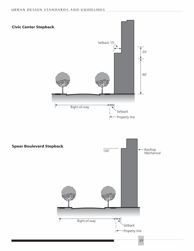
◗ Provide an upper level buildingsetback of at least fifteen feet (15’) at alevel sixty to eighty feet (60’ to 80’)above grade on new buildings on thesouth side of 14th Avenue betweenCherokee Street and Grant Street.
GUIDELINES
◗ Buildings on Colfax Avenue betweenSpeer and 14th Street should be set back a minimum of ten feet (10’)from the property line.
◗ Buildings on 14th Avenue betweenSpeer Boulevard and Grant Streetshould be set back a minimum of tenfeet (10’) from the property line.
◗ On blocks fronting on or near CivicCenter Park, an upper level buildingstepback should be provided in newbuildings that face the park or historicbuildings. A building stepback of atleast fifteen feet (15’) deep should beprovided at a height above grade
between sixty and eighty feet (60’ and80’). This approximates the height ofthe cornice lines or roof lines of theCity and County Building, the CarnegieLibrary (Annex III) Building, and theState Capitol. This stepback need notapply to buildings whose height is lessthan one hundred feet (100’).
◗ Other ways of establishing a corniceline and scale compatible with thehistoric Civic Center buildings may beacceptable.
◗ The architecture and siting of CivicCenter projects shall reflect theimportance of this sub-area throughscale, proportion, extensive use ofhigh-quality materials in relation toother civic structures, to open spaceand the public realm.
◗ Any building setback should be usedfor pedestrian amenities such as widersidewalks, street trees, landscaping,outdoor seating areas, pocket parks orpedestrian lighting.
c. Speer Boulevard Sub-Area
NOTE: Rules and Regulations governingdevelopment on Commercial Corridorsalso apply to this sub-area.
INTENT
◗ To frame and provide scale to theparkway, enhancing its significance.
◗ To reinforce Speer’s character as anhistoric parkway.
◗ To create buildings that are“sculpted” to reduce the overallappearance of mass.
◗ To contribute to a consistent frontsetback without abrupt transitions orencroachments.
STANDARDS
◗ Buildings shall be built between tenand twenty feet (10’-20’) of the
G O L D E N T R I A N G L E – B - 8 - G
18
Right-of-way
Property line
Setback
60'
20'
Setback 15'
Right-of-way
Property line
Setback
100' RooftopMechanical
U R B A N D E S I G N S TA N D A R D S A N D G U I D E L I N E S
19
Civic Center Stepback
Speer Boulevard Stepback

property line adjoining the street forno less than sixty-five percent (65%)of each zone lot frontage. The setbackshall be used for landscaping orpedestrian amenities.
◗ The land between Speer Boulevard andthe building shall be landscaped orused for pedestrian amenities such aswider sidewalks, street trees,landscaping, outdoor seating areas,pocket parks or pedestrian lighting.
◗ The zoning code requires that anystructure over one hundred feet (100’)tall on a zone lot of at least 15,000square feet shall have that portion of thefacade facing Speer greater than onehundred feet (100’) above ground levelset back at least twenty feet (20’) fromthe right of way of Speer Boulevard,unless waived through the design reviewprocess (see Guidelines below).
◗ All new buildings located on parcelsadjacent to Speer Blvd. shall continuethe linear quality of the parkway byaligning and orienting their primaryfacade to the Boulevard. Buildingspresenting rear or side facades to SpeerBlvd. are undesirable. Minimize curbcuts along the Parkway with accessfrom side streets. Allow a maximum ofone curb cut per parcel only when noalternative side street access is available.New parking lots should not frontonto Speer Boulevard.
GUIDELINES
◗ The Speer Boulevard setback areashould reinforce the parkway characterthrough landscaping or pedestrianamenities.
◗ The required additional ten foot (10’)setback (for a total of twenty feet [20’]from the ROW) for the portion ofbuildings taller than one hundred feet(100’) may be waived provided the
mass and bulk of the entire structure isarticulated in a manner to avoidovershadowing Speer Boulevard (seeGlossary). This may be accomplishedby means such as reducing thebuilding mass through multiple full orpartial setbacks.
◗ Alleys intersecting Speer Boulevardcreate irregularly-shaped blocks andawkward development parcels.Therefore, to facilitate redevelopmentand public safety, alleys may be vacatedprovided that other design goals aremet (see Standards and Guidelinesunder “Street Grid”.)
d. Colfax Avenue Sub-Area
NOTE: Rules and Regulations governingdevelopment on Commercial Corridorsalso apply to this sub-area.
INTENT
◗ To provide a continuous street frontage.
◗ To enhance and improve the publicrealm where inadequate public rightof way exists.
STANDARDS
◗ New development shall considerprevailing Colfax setbacks (usually aminimum of ten feet). The setbackshall be used for pedestrian amenitiessuch as sidewalks, trees, pedestrianlights, or outdoor seating areas.
GUIDELINE
◗ Buildings should be located betweenten feet and twenty feet (10’-20’) of theproperty line adjoining the street forno less that sixty-five percent (65%) ofeach zone lot frontage. The setbackshould be used for landscaping orpedestrian amenities.
e. Broadway-Lincoln Sub-Area
NOTE: Rules and Regulations governingdevelopment on Commercial Corridorsalso apply to this sub-area.
G O L D E N T R I A N G L E – B - 8 - G
20
Generous sidewalk width
(Bannock St.)
Primary building entry oriented
towards street (Cherokee St.)

INTENT
◗ To provide a continuous street wall onBroadway with building fronts broughtto the property line.
◗ To use new construction and reuse ofappropriate existing buildings to createa strong visual identity for theBroadway-Lincoln Corridor.
◗ To re-knit the traditional urban fabric.
STANDARD
◗ Buildings shall be located at theproperty line adjoining the street forno less than 65% of each zone lotfrontage. Any additional buildingsetback shall be used for landscapingor pedestrian amenities.
GUIDELINE
◗ Buildings, including parkingstructures, should create a continuousstreet wall adjacent to the Broadwayand Lincoln ROW.
B. A. A. SITE B. ARCHITECTURE 1. FORM AND MASSING
a. Building Adjacencies
INTENT
◗ To reinforce the grid system of streets,blocks and alleys, and the existingurban pattern.
◗ To spatially define the street spaces bybuilding form and massing.
◗ To modulate building massing asappropriate to the neighborhood sub-area and immediate environment.
STANDARDS
◗ Tall buildings adjacent to lowerstructures shall establish scalerelationships with neighboringbuildings through methods such ashorizontal alignment of architecturalfeatures and fenestration, similarproportions, similar use of materials
and stepbacks reflecting the height ofthe lower structure.
GUIDELINES
◗ When new development is larger inheight and mass than the existingcontext, building mass should bevaried through changes in wall planeand building height to moderatescale changes between developments.
b. Relationship to the street
and public spaces
INTENT
◗ To create a walkable neighborhoodby providing active pedestrian-oriented public uses on the groundfloors of mixed-use projects, directsidewalk access enhancedstreetscaping, and building designwith human scale and detail.
◗ To reinforce pedestrian activity andcirculation along the street, create asmany external street-oriented entries aspossible to ground floor pedestrianactive uses.
◗ To create a community identity and develop the Golden Triangleneighborhood into a distinctive place through the overall
U R B A N D E S I G N S TA N D A R D S A N D G U I D E L I N E S
Greater detail at residential building entrance (Elati & 12th)
21

composition of spaces, juxtapositionof buildings, unique architecturalcharacter and details.
◗ To provide community open spacewithin the neighborhood; to createinformal gathering places.
◗ To reinforce the grid pattern of streetsand alleys, the block pattern, and theexisting urban structure.
1. Entries and Corners
STANDARDS
◗ All buildings shall provide at least oneprimary building entry orienteddirectly to a public street.
◗ All pedestrian active uses with streetlevel, exterior exposure shall provide atleast one direct pedestrian entry fromthe street.
GUIDELINES
◗ Each building should have one ormore clearly identifiable front entriesthat face the street for each majorstreet facade.
◗ The use of street-oriented entriesserving small groups of dwelling unitsin large, multiple unit buildings isexpected; however, street-facing groundfloor residential units should haveindividual exterior entries.
◗ Entries to buildings should have directpedestrian access to the street on whichthey front.
◗ The majority of street oriented frontageof any building should be occupied bypedestrian active uses that are visuallyand physically accessible from thestreet (see glossary).
◗ Entries to ground floor pedestrianactive uses and building lobbiesshould be emphasized throughchanges in plane, differentiation inmaterial and/or color, greater level ofdetail and enhanced lighting. Durable,
high-quality materials such as stone,brick and pre-cast concrete areappropriate finishes on the lowerportions of buildings fronting ontopedestrian-traffic areas.
2. Orientation
STANDARDS
◗ At least sixty-five percent (65%) of thebuilding façade within the lower eightyfeet (80’) shall be oriented parallel tothe street on which it fronts.
GUIDELINES
◗ New construction should create astrong and attractive street edge closeto the sidewalk.
◗ Automotive-oriented uses should belocated away from public sidewalksand street frontages in a manner thatsupports the desired urban pedestriancharacteristics of the neighborhood.
3. Ground Floor Uses
STANDARDS
◗ The ground floor area fronting thestreet shall be occupied by pedestrianactive commercial or residential uses(see glossary).
GUIDELINES
◗ Drive aisles, ceiling heights, utilitylayouts and structural openings shouldbe designed to be consistent withfuture occupancy of the building withpedestrian-active uses.
2. BUILDING FACADES & ROOFSa. Facades
INTENT
◗ To provide human scale throughchange in plane, contrast and intricacyin form, color, and materials.
◗ To avoid large areas of undifferentiatedor blank building façade.
◗ To create a comfortably scaled andthoughtfully detailed urbanenvironment through the use of well-
G O L D E N T R I A N G L E – B - 8 - G
22
Building material and
architectural element variety (PS1
Charter School, Delaware & 11th)

designed architectural forms and details.
◗ To provide for the comfort and interestof the pedestrian environment throughthe provision of human-scaledarchitectural character.
◗ To provide lower floor facades thatinsure the visibility of pedestrian activeuses, and provide a more transparent,architecturally detailed and human-scaled design along the sidewalk.
◗ To provide a more solid wall with apattern of individual windows at theupper floors in order to provide greatervariety of scale through fenestrationpatterns, architectural elements, surfacerelief, textures and materials.
◗ To enhance street intersections throughspecial corner treatment of buildings.
1. Architectural Scaling Elements
STANDARDS
◗ Each building facade facing a publicstreet shall, at minimum, incorporatearchitectural scaling patterns thatutilize three or more of the followingscaling elements:
1. Expression of building structuralelements through floors (banding,belt coursing, etc.), columns(pilasters, piers, etc.), or foundation(watertables, rustications)
NOTE: Architectural features inparentheses are provided for exampleonly and are not intended to imply apreference for historical styles.
2. Patterns of window and dooropenings that are emphasizedthrough the use of sills, lintels,pediments, mullions, muntins, andother scale providing elements
3. Change in color
4. Change in texture
5. Change in material module or pattern
6. Patterns of architectural ornamentintegral to the building facade
◗ Required scaling elements shall beintegral to the building form andarchitecture, not applied.
◗ Architectural scaling patterns shalloccur both horizontally and vertically.
GUIDELINES
◗ Ground floor commercial frontageshould be distinguished fromresidential facades through suchmethods as height, material, detail,percentage of glazing, etc, and may beused to establish a strong buildingbase or street level corner features.
◗ Material changes should occur atinside corners or be delineated by aspecific transitional detail such as abelt course, cap or reveal.
◗ Consideration should be given tooverall composition of buildingmassing and organization of itsarchitectural components. Careshould be used when creating facadesand openings so as to reinforce thebasic massing and organization of thebuilding.
2. Surface Variation
STANDARDS
◗ Each change of material shall involve aminimum one-inch (1”) variation inwall plane. Reveals shall be not lessthan one inch (1”) deep and one inch(1”) wide.
GUIDELINES
◗ Dimensions of reveals should reinforcethe architectural character of thebuilding through separation ofdifferent materials, articulation ofsurfaces, and relationship to underlyingstructure, proportion, and details.
U R B A N D E S I G N S TA N D A R D S A N D G U I D E L I N E S
23

3. Windowsa. Transparency
STANDARDS
◗ Clear glass shall have an exteriorreflectance rating not to exceed .20.
◗ No reflective coating shall be on theexterior surface of the glass.
GUIDELINES
◗ Clear, “Low-E”, or slightly tintedglazing should be used to insure thevisibility of pedestrian orientedcommercial uses.
◗ Minimal use of opaque glass isacceptable to continue glazing patternsin areas where screening structures andutilities is required.
◗ Spandrel glass may be used to screenservice/utility areas, structuralelements, or to continue a patterncreated as a result of screening.
b. Window to Wall RatioSTANDARDS
◗ Ground floor commercial facades shallhave a minimum of sixty percent(60%) transparent materials.
◗ Between twenty-five and sixty percent(25%-60%) of upper floor facades, upto eighty feet (80’), shall be transparentglazing. Spandrel glass may be used toscreen service, utility or structuralelements, or to continue a patterncreated as a result of screening.
GUIDELINES
◗ For mixed-use developments, a varietyof glass-wall ratios that reflect thedifferent uses within a building areexpected. Typically, this ischaracterized by a lower glass to wallratio in residential uses and a higherglass to wall ratio in commercial uses.Second floor mezzanine levels mayconform to either characteristic.
◗ Non-reflective glass curtain wallsystems are acceptable for commercialportions of buildings.
c. DetailingSTANDARDS
◗ The height of windows serving theresidential portion of any buildingshall be equal or greater than theirwidth. All windows serving theresidential portion of any buildingshall be set into the building facade aminimum of three inches (3”) fromthe surrounding wall surface.
◗ Storefront systems in mixed use orcommercial buildings shall reflect thedimensions and proportions ofbuilding bays and modules in order tovisually bring the building mass andstructural system to the ground.
GUIDELINES
◗ All glazing should be recessed andsubdivided by systems of framing andmullions to reinforce architecturalscaling elements.
◗ Windows may be proportioned incontemporary configurations, or mayreflect the more vertically oriented,deeply set punched openingcharacteristics typical of traditionalDenver architecture.
◗ Size and proportions of storefrontsystems in mixed use or commercialbuildings should use devices such ascolumns, piers and/or wall areas tosubdivide and create rhythm whilevisually bringing the building massand structural system to the ground.
◗ Portions of a building facade that mustrestrict glazing for functional reasonsshould conform to the architecturalscaling standards.
G O L D E N T R I A N G L E – B - 8 - G
24
Ground floor storefront windows
(Acoma and 11th)
Historic neighborhood masonry
(Acoma and 9th)
Contemporary masonry
(Acoma and 11th)

b. Roofs
INTENT
◗ To develop building tops witharchitectural silhouettes which adddefinition to the Denver skyline, withconsideration given for all vantagepoints, not just as viewed in elevationfrom street level.
◗ To integrate all building systemswithin a complete architectural form.
STANDARDS
◗ All rooftop building systems shallbe incorporated into the buildingform in a manner integral to thebuilding architecture in terms ofform and material.
◗ All mechanical, electrical, andtelecommunications systems shall bescreened from view of surroundingstreets and structures.
GUIDELINES
◗ Roof forms should relate to thecontext in which they are viewed in terms of height, proportion, formand materials.
◗ Roof forms should be used tointegrate roof equipment,telecommunications equipment andother devices so as to express/concealthem as architectural elements.
◗ The architecture of the building’s upperfloors and termination should completethe building form within an overalldesign concept for the base, middle andtop that works in concert with thearchitectural scaling requirements.
c. Materials
INTENT
◗ To insure the consistent use of highquality materials appropriate to theurban environment.
◗ To reinforce the masonry traditions ofDenver and its regional architecture.
◗ To allow the evolution ofdevelopment patterns to include newtechnologies and materials thatcontribute to the neighborhoodcharacter, such as architectural metals,and materials that express depth,dteail and modularity enhanced bythe sunny regional climate.
◗ To relate new construction to existingbuildings through the use of similarscale elements present in standardbrick, modular stone, cast stoneaccents, concrete masonry, architecturalmetals and detailed stucco.
STANDARDS
◗ The first floor exterior wall surfacesshall incorporate a majority ofmasonry materials, such as stone, caststone, brick, special surface concretemasonry (split face, burnished, etc.)
◗ EIFS (Exterior Insulating FinishSystems) shall not be used as exteriorcladding on building ground floorfacades.
◗ On exterior wall surfaces viewablefrom the street, stucco and EIFSshould incorporate architecturalscaling elements similar to masonryconstruction, e.g. sills, belt coursing,reveals, wall caps, pilasters, offsetmassing.
GUIDELINES
◗ All building materials should beselected with the objectives of qualityand durability in the urban contextas well as to produce a positive effecton the pedestrian environmentthrough such qualities as scale, colorand texture.
◗ Carefully detailed combinations ofmaterials should be used to reinforcearchitectural scaling requirements.
◗ Architectural metals, cast in placeconcrete, architectural concrete
U R B A N D E S I G N S TA N D A R D S A N D G U I D E L I N E S
25

masonry units, tile, glass, glass blocksystems, etc. are acceptable materialswhen properly finished and detailed.
◗ Stucco systems may be used abovethe ground floor. When used onupper floors, stucco systems shouldbe combined with street-levelmaterials such as brick, stone, or pre-cast concrete to provide anintegrated material vocabulary.
d. Building accessories and
components
INTENT
◗ To integrate all building accessorieswithin a complete architectural form.
◗ To prevent excessive contrast in nightlighting levels.
◗ To ensure a safe pedestrianenvironment.
◗ To create a pedestrian environmentwith visual interest.
1. Balconies
STANDARDS
◗ Balconies and terraces shall beincorporated into vertical andhorizontal shifts and building massingwherever possible to avoid buildingfaces that are dominated bycantilevered balcony projections.
GUIDELINES
◗ Balconies should be consistent withthe overall architectural character of thebuilding.
◗ Cantilevered balcony railings shouldbe designed to be as open as possible.
2. Porte cocheres and loading areas
STANDARDS
◗ Passenger loading areas shall either beat the public street curb or interior tothe development and not prominentfrom the public right of way.
◗ Design of vehicular access shallminimize size and number of curb cuts.
GUIDELINES
◗ Passenger loading areas should bedesigned for minimal visual andphysical impact on public right of way.
◗ Exterior loading areas should not be located between the building and the street.
◗ On-street loading areas should not cutinto the tree lawn or sidewalk, but maybe located in the parking lane at thepublic street curb.
3. Awnings and Canopies
STANDARDS
◗ Awnings and canopies shall becompatible with building design interms of materials, details, massing and form.
◗ On awnings and canopies extendingover the public right of way, internallighting and advertising shall not bepermitted. Street-level awningss andcanopies may be externallyilluminated. Building or tenant nameand address may be printed on theawnings/canopies. All proper permitsmust be obtained to extend over theright of way.
4. Building Lighting
STANDARDS
◗ Site lighting shall be contained withinthe site, providing cut-off typeluminaires in non-accent applications,such as parking and utility use.
◗ Light levels shall be designed to avoid extreme contrasts between lightand shadow.
◗ If exposed to public view, buildinglight fixtures shall be incorporated soas to be integral with the buildingarchitecture.
G O L D E N T R I A N G L E – B - 8 - G
26
Compatible awnings (Bannock St.)

GUIDELINES
◗ Building lighting should enhancesafety and security and be shielded tominimize glare and light pollution.
◗ All lighting fixtures should bearchitecturally compatible in terms ofmaterials, details, massing and form.
5. Accessible Ramps, Stairs, Elevators
STANDARD
◗ If exposed to public view, all otherbuilding accessories shall becompatible with building design interms of materials, details, massingand form.
6. Mechanical equipment
STANDARD
◗ All rooftop building systems shall beincorporated into the building form ina manner integral to the buildingarchitecture.
GUIDELINE
◗ All roof-mounted electrical,mechanical, and telecommunicationssystems should be screened from viewof surrounding streets and structures.
7. Building Security Bars and Fencing
STANDARD
◗ Chain link and razor wire fencingshall not be visible from the publicright of way.
◗ Security fencing shall be accomplishedwith architectural quality railing.
GUIDELINES
◗ Limited use of exterior security barsmay be appropriate if they aredesigned in a architectural manner.
C. LANDSCAPEARCHITECTURE
1. LANDSCAPING ON PRIVATE PROPERTY
a. Green Space
INTENT
◗ To provide attractive andarchitecturally compatible landscapeand/or hard surface design in areasexposed to public view, and/oraccessible to the public.
◗ To provide landscaping and/or hardsurface design that reinforcespedestrian activity at the street, such assidewalk cafes, window shopping andother display of goods.
◗ To insure that landscaping reinforcesground level transparency and/or awelcoming character to ground leveluses facing the street.
U R B A N D E S I G N S TA N D A R D S A N D G U I D E L I N E S
Informal outdoor gathering space
27
◗ To help create a special identity for thedistrict through the design of private,street oriented landscaping.
◗ To create informal public gathering places.
◗ To help mitigate existing largely blankstreet facing facades.
◗ To maximize the percentage of openspace that is permeable and green space.
◗ To coordinate front setbacklandscaping and/or hard surface designwith the streetscape design within thepublic R.O.W.
◗ To use both public and private outdoorspace to enhance both the privacy ofresidences and the pedestrianexperience.
STANDARDS
◗ Landscaping within the allowedsetback areas on the site shallreinforce the ROW landscapingthrough more formal, urbanplacement of plant material.
◗ Ground level mechanical equipment,utility pedestals, loading docks, trashenclosures, meters and otherutilitarian elements shall be screenedfrom public view.
◗ Garden space illumination shall beaccomplished with low-level lightingwhich does not produce glare intoadjacent spaces.
GUIDELINES
◗ Fences or walls on public frontagesshould be supplemented withlandscaping.
◗ Mature trees should be retained andincorporated whenever possible intosite landscaping.
b. Parking Lot Landscaping
INTENT
◗ To screen, mitigate and/or soften the edges of larger parking lots frompublic view.
◗ To clearly demarcate parking lots fromthe street, sidewalks, and otherpedestrian paths.
◗ To frequently interrupt and/or dividethe hard surfacing of larger parking lotsexposed to public view with trees andother landscaping.
◗ To help create a special identity for thedistrict through the coordination ofprivate, street oriented landscaping.
◗ To coordinate street-oriented parkinglot edge landscaping with thestreetscape design within the publicR.O.W.
STANDARDS
◗ Surface parking lots shall adhere toDenver’s Rules and Regulations for theLandscaping of Parking Areas.
◗ Parking lot screen walls shall relate toassociated building architecture interms of materials, details, massingand form.
GUIDELINES
◗ Parking lot landscaping should includea secondary planting of ornamental orstreet trees in a landscaped plantingbed along the parking lot edge in orderto provide a double tree lawn.
c. Lighting
INTENT
◗ To enhance and emphasize pedestrianactivity at the street, such as sidewalkcafes, window shopping, display ofgoods, etc.
◗ To create interest, and a safe andwelcoming character along street facingfrontages.
G O L D E N T R I A N G L E – B - 8 - G
28
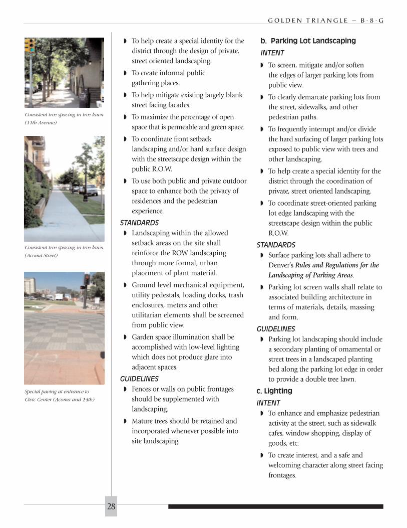
Consistent tree spacing in tree lawn
(11th Avenue)
Consistent tree spacing in tree lawn
(Acoma Street)
Special paving at entrance to
Civic Center (Acoma and 14th)
◗ To reinforce architectural elementssuch as entries, structural bays, shopwindows, etc., and to emphasize suchelements generally at street level.
◗ To avoid glare, both to pedestrians andto residents in nearby property(including internal and roof-topparking garage lighting).
◗ To insure that parking lot lighting doesnot create glare onto the street and/oronto adjacent property.
◗ To provide high quality parking lotlight poles and luminaires.
STANDARDS
◗ Public area and parking lot lighting shallbe low cut-off fixtures to avoid glare.
GUIDELINES
◗ Business signs and building entrancesmay be illuminated by external orindirect source only to providenighttime visibility, enhance safety,and avoid glare.
2. PUBLIC R.O.W. AND OTHERPUBLIC SPACES
a. Street trees and Landscaping
INTENT
◗ To create a uniform street landscapecharacter.
◗ To create tree-lined streets withuniform tree spacing.
◗ To provide easily maintained andwalkable landscaping in the tree lawnin order to encourage on-street parkingand pedestrian activity.
◗ To create growing environments thatencourage healthy and fully developedtrees and other plant material.
STANDARDS
◗ Landscaping shall be consistent withthe City of Denver Streetscape DesignManual, and streetscape template
shown in the Golden TriangleNeighborhood Plan (see appendix).
◗ Trees shall be planted in a uniformpattern with equal spacing, thirty-fivefeet (35’) on center, centered in thetree lawn width.
◗ Trees in grates shall be used alongColfax Ave, Broadway, Bannock andCherokee from Colfax to 13th Avenue.All other areas are to be planted withtree lawns.
◗ Trees used in the ROW shall bedeciduous shade species, notornamental species, as approved byCity Forester.
GUIDELINES
◗ Tree spacing may be slightly modifiedwith the approval of the City Forrester.
◗ Limited paving in the treelawn toallow pedestrian cross-access from the street may be allowed throughdesign review.
b. Pedestrian lighting and
street lights
INTENT
◗ To create a uniform pedestrian lightingcharacter for the Golden Triangle.
◗ To allow some sub-area, but notindividual building, exceptions to theuniform character where appropriatein order to help create special identity.
STANDARDS
◗ Pedestrian lights shall be installed atleast fifty feet (50’) apart; sixty to onehundred fifteen feet (60’-115’) isrecommended.
◗ Color-corrected high-pressure sodiumlamps shall be used.
◗ The same light styles shall be usedthroughout the district to create aunifying streetscape design theme:
◗ Acorn type luminaires requiredin the Denver Streetscape Design
U R B A N D E S I G N S TA N D A R D S A N D G U I D E L I N E S
29

Manual shall be used in mostlocations.
◗ Parkway Globe luminaires arerequired on Speer Boulevard,Acoma Street north of 9th Ave.,and West 14th Avenue Parkway,as well as in Denver parks.
GUIDELINES
◗ Banner sign mountings should beinstalled at every other pedestrian lightto announce special events andneighborhood programs.
◗ Hanging plants should be installedfrom pedestrian lights.
c. Sidewalks and pedestrian
area paving
INTENT
◗ To provide sidewalks along every street.
◗ To provide sidewalk continuity byminimizing the number and width ofcurb cuts.
◗ To provide sidewalk continuitythrough the consistent use of pavingmaterials.
◗ To develop special crosswalk /intersection treatment wheredesignated by the neighborhood plan.
◗ To preserve existing stone sidewalksand curbs.
STANDARDS
◗ Detached sidewalks shall be five feet(5’) minimum to ten feet (10’)minimum (see appendix for locations).
◗ Treelawns shall be eight feet (8’)minimum and curbside amenity zonesshall be five feet (5’) minimum (seeappendix for locations).
◗ Existing stone sidewalks shall bepreserved and maintained.
◗ New sidewalks shall be uncoloredconcrete.
GUIDELINES
◗ Private use of ROW is subject torevocable permits; a five foot (5’)continuous unobstructed walkwaymust be maintained.
d. Street Furniture and Identity
Elements
INTENT
◗ To implement Denver StreetscapeDesign Manual standards.
◗ To allow some sub-area, but notindividual building, exceptions to theuniform character.
◗ To locate street furniture where peopleare likely to congregate, and/or woulddesire to spend time.
◗ To emphasize entry points to theDistrict.
STANDARDS
◗ Install pedestrian lights as perspecifications and spacing as noted inthe Denver Streetscape Design Manual.
◗ Install Civic Center sub-area pedestrianlights as per the Civic Center DesignGuidelines.
◗ Incorporate bike racks into all projects.
◗ On Speer Boulevard, West 14th Ave.,and Acoma Street, the Denver ParkwayGlobe is the standard fixture.
◗ On the remaining streets, the DenverAcorn is the standard fixture.
e. General Street Design
INTENT
◗ To mitigate traffic volume and speedon local and collector streets.
◗ To avoid paving or elimination of the treelawn and/or elimination of street trees.
◗ To reduce the pedestrian crossingdistance through the use of ‘bulb-out’curbs in locations as shown in theappendix on the streetscaperequirements map.
G O L D E N T R I A N G L E – B - 8 - G
30
Shaded benches (Acoma Plaza)
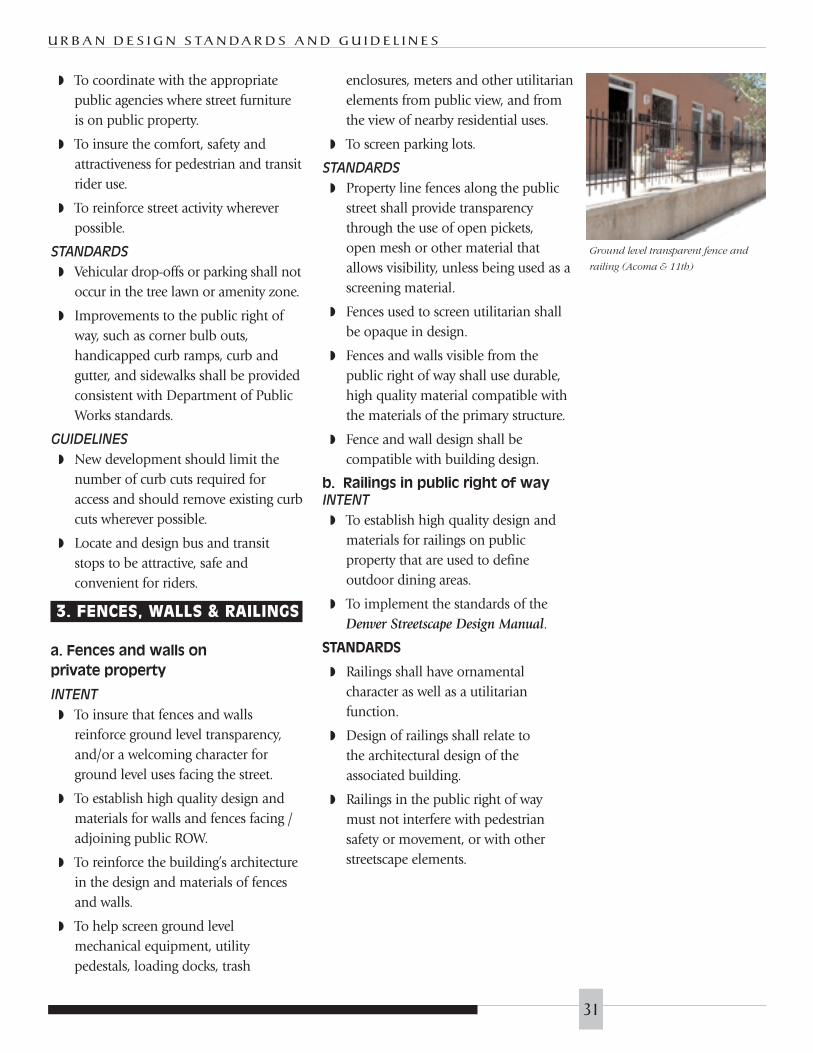
◗ To coordinate with the appropriatepublic agencies where street furnitureis on public property.
◗ To insure the comfort, safety andattractiveness for pedestrian and transitrider use.
◗ To reinforce street activity whereverpossible.
STANDARDS
◗ Vehicular drop-offs or parking shall notoccur in the tree lawn or amenity zone.
◗ Improvements to the public right ofway, such as corner bulb outs,handicapped curb ramps, curb andgutter, and sidewalks shall be providedconsistent with Department of PublicWorks standards.
GUIDELINES
◗ New development should limit thenumber of curb cuts required foraccess and should remove existing curbcuts wherever possible.
◗ Locate and design bus and transitstops to be attractive, safe andconvenient for riders.
3. FENCES, WALLS & RAILINGS
a. Fences and walls on
private property
INTENT
◗ To insure that fences and wallsreinforce ground level transparency,and/or a welcoming character forground level uses facing the street.
◗ To establish high quality design andmaterials for walls and fences facing /adjoining public ROW.
◗ To reinforce the building’s architecturein the design and materials of fencesand walls.
◗ To help screen ground levelmechanical equipment, utilitypedestals, loading docks, trash
enclosures, meters and other utilitarianelements from public view, and fromthe view of nearby residential uses.
◗ To screen parking lots.
STANDARDS
◗ Property line fences along the publicstreet shall provide transparencythrough the use of open pickets, open mesh or other material thatallows visibility, unless being used as ascreening material.
◗ Fences used to screen utilitarian shallbe opaque in design.
◗ Fences and walls visible from thepublic right of way shall use durable,high quality material compatible withthe materials of the primary structure.
◗ Fence and wall design shall becompatible with building design.
b. Railings in public right of wayINTENT
◗ To establish high quality design andmaterials for railings on publicproperty that are used to defineoutdoor dining areas.
◗ To implement the standards of theDenver Streetscape Design Manual.
STANDARDS
◗ Railings shall have ornamentalcharacter as well as a utilitarianfunction.
◗ Design of railings shall relate to the architectural design of theassociated building.
◗ Railings in the public right of waymust not interfere with pedestriansafety or movement, or with otherstreetscape elements.
U R B A N D E S I G N S TA N D A R D S A N D G U I D E L I N E S
Ground level transparent fence and
railing (Acoma & 11th)
31
DESIGN REVIEW PREMIUMS
G O L D E N T R I A N G L E – B - 8 - G
32

RMC Section 59.399.4(3) allows theplanning office to grant a density incentiveof 1 FAR (to a project maximum of 7:1FAR) if an applicant submits the entireproject to design review. This incentivemay be granted based on:
◗ All facades facing public rights of wayare consistent with these designstandards and guidelines.
◗ The entire height of the building isconsistent with these standards andguidelines.
◗ Other urban form goals of theComprehensive and Golden TriangleNeighborhood plans are met,including:
◗ Building height that is appropriateto the sub-area (see page 33).
◗ Street-facing facades includeactive uses such as retail, office orresidential units.
U R B A N D E S I G N S TA N D A R D S A N D G U I D E L I N E S
33

SIGN DESIGN REVIEW
G O L D E N T R I A N G L E – B - 8 - G
34

Sign review is a separate zoning processwhich may be subject to design review.Sign size and location are regulated by theDenver Zoning Code.
INTENT
◗ To insure that building architectureappropriately accommodates neededsignage in the design of the facades.
◗ To insure that lighted signs are locatedto minimize glare onto adjoiningproperty.
◗ To improve vehicular and pedestriansign visibility.
◗ To create an organized and inter-related system of signs, sign structures,lighting and graphics.
◗ To provide high quality signage andgraphic design and durable materialsappropriate to an urban setting.
◗ To create signs and graphic elementsthat are appropriate to and expressiveof the use they identify.
◗ To create signs and graphic elementsthat are related to and/or respect thearchitecture of the building whichthey serve.
A. LOCATION
STANDARDS
◗ All signs shall conform to the DenverZoning Code.
◗ Commercial or mixed-use buildingsshall provide locations on thecommercial areas of the buildingfacade that are specifically designed toaccomodate changeable tenant signageincluding wall signs, projecting signsand window signs. Structure, materials,detailing and power sources shall bedesigned with a consideration ofsignage installation requirements and
shall be readily adaptable as tenantsign needs change.
◗ Signage locations shall be oriented tothe public ROW and shall avoid facingresidential uses whenever possible.
GUIDELINES
◗ Multiple street signs on a block faceshould be uniformly designed.
B. STYLE
STANDARDS
◗ All signs shall conform to the DenverZoning Code.
◗ Direct exposure of light sources andinternally illuminated signs shall beavoided in residential areas. Indirectand external light sources shall bethe preferred option where lightingis required.
GUIDELINES
◗ Sign style shall be compatible with building architecture andcoordinate with streetscape designwithin the district.
◗ Shielded external direct lighting orindirect internal lighting of signcharacters and figures should be usedto light signs. Exposed light sourcesand fully illuminated sign faces shouldnot be used.
◗ Building architecture should providelocations for attaching necessary andappropriate signs for identification of businesses, building names and addresses.
◗ Signs should creatively use two- andthree- dimensional form, profile, andiconographic representation: lighting,typography, color, and materials inexpressing the character of the use, theidentity of the development, thecharacter of the neighborhood, andthe architecture of the building.
U R B A N D E S I G N S TA N D A R D S A N D G U I D E L I N E S
35
Building signage (Acoma St.)

◗ Signs should fit within the architecturalfeatures of the facade and complimentthe building’s architecture.
◗ Signs should not overlap and concealarchitectural elements.
C. SIZE
STANDARDS
◗ All signs shall conform to the DenverZoning Code.
GUIDELINES
◗ Signs should not dominate thebuilding facade.
◗ Lettering should be legible to both thepedestrian and automobile traffic.
G O L D E N T R I A N G L E – B - 8 - G
36
U R B A N D E S I G N S TA N D A R D S A N D G U I D E L I N E S
37
PUBLIC ART PREMIUMS

G O L D E N T R I A N G L E – B - 8 - G
RMC Section 39-399.4(f) allows a floorarea premium equal to 25% of the zonelot area to be granted for public art.
In order to obtain approval of theproposed artwork, the developer mustsubmit a proposal to CPDA/Urban Designprior to purchasing or commissioning theartwork for consideration. The developeris strongly encouraged to meet with CPDAstaff as early as possible and prior tosubmitting the proposal to discuss possibleand acceptable concepts.
A. Qualifications
The premium may be applied for andgranted if:
◗ The public art costs one-percent (1%)of the cost of building construction orrehabilitation; or,
◗ The public art costs at least fivehundred thousand dollars ($500,000).
B. Art Approval
A Public Art Committee will undertakereview of the public art proposal. TheDirector of CPDA appoints the committeemembers from the following individuals:
◗ An architect or other professionaldesign staff member of CPDA, whoserves as the Committee Chair;
◗ The property owner or his/herdesignee;
◗ The Director of the Denver ArtMuseum or his/her designee;
◗ The Director of Mayor’s Office of ArtCulture and Film or his/her designee;
◗ A resident from the neighborhood;
◗ A local artist.
Before purchasing or commissioning anypiece of art, the developer must first meet
with the Public Art Committee to discussthe general characteristics and possibleconcepts for the artwork. Following thismeeting, a proposal from the developermust be submitted to the committee forconsideration.
The proposal must contain a written andgraphic description of the project art,including the following appropriateinformation:
◗ Site plans of the vicinity where the artis to be located;
◗ Elevations;
◗ Perspectives;
◗ Details of structural elements;
◗ Verification of costs; and,
◗ Maintenance requirements,maintenance schedule and source ofmaintenance funds.
The Public Art Committee will make arecommendation to the Director of CPDA,who makes the final determination onacceptance or denial of the artwork andgranting of the density premium.
The Public Art Committee must reviewand approve any changes in the designand/or concept of the project art after thefinal proposal has been approved.
CPDA may, at its sole discretion, revise thisprocess as necessary to respond toindividual circumstances of differentprojects.
C. Requirements
1. Location
The public art must be located outside thebuilding or on the exterior surface of thebuilding, available and accessible to thegeneral public.
38

U R B A N D E S I G N S TA N D A R D S A N D G U I D E L I N E S
39
Any part of the artwork in the publicright of way must be granted theappropriate permits.
2. Art Types
Public art includes, but is not limited to,the following:
◗ Sculpture: in the round, bas relief,mobile, fountain, kinetic, andelectronic, in any material orcombination of materials;
◗ Painting: all media, including portableand permanently affixed works;
◗ Graphic arts: printmaking anddrawing;
◗ Mosaics;
◗ Photography;
◗ Crafts: in clay, fiber and textiles, wood,metal, plastics, stained glass, and othermaterials both functional andnonfunctional;
◗ Mixed media: any combination offorms or media, including collage;
◗ Earth works and environmentalinstallations; and,
◗ Decorative or ornamental elementswhich are designed by practicingartists.
The following elements will generally notbe considered acceptable forms of artunder this program:
◗ Directional elements such assupergraphics and signage;
◗ Objects which are mass produced in astandard design such as playgroundequipment, benches and chairs;
◗ Reproductions of original works of art,except in such cases as film, video,photography, printmaking and othermedia arts;
◗ Landscape architecture and gardening,except where the elements are designedby an artist and are an integral part of alarger piece of artwork;
◗ Renovation of historic facades or otherhistorical elements functional to theproject;
◗ Commercial elements used to promoteor advertise the project; and,
◗ Other elements of the developmentproject which are functional or directlyrelated to the operation of the project.
3. Review Criteria
The developer is encouraged, but notrequired, to utilize a local artist in thedevelopment of the public art.Additionally, the Public Art Committee willuse the following criteria in evaluating theproposal:
◗ Appropriateness of relationship to project;
◗ Artistic excellence;
◗ Strong contribution to the historic,ethnic or other characteristics of the site;
◗ Susceptibility to wear and vandalism;
◗ Longevity and permanence of materials;
◗ Maintenance schedule and source ofmaintenance funds;
◗ Mediation of environmental hazards;and,
◗ Compliance with applicable publicsafety codes.

G O L D E N T R I A N G L E – B - 8 - G
GLOSSARY
40

U R B A N D E S I G N S TA N D A R D S A N D G U I D E L I N E S
Amenity Zone: A portion of the public right of way that contains streetscape elements.
Attached Sidewalk: Sidewalk immediately adjacent and attached to a street curb
Commercial Corridors: Streets, avenues, parkways, and boulevards as specified in theadopted Review Criteria for Development along Commercial Corridors.
CPDA: Community Planning and Development Agency
Density Premium: Additional gross floor area allowed by zoning in exchange for definedpublic benefits
Detached Sidewalk: Sidewalk separated from the curb by a tree lawn or amenity zone
DPR: Denver Department of Parks and Recreaton
E.I.F.S.: Exterior Insulation Finish System
FAR: Floor Area Ratio, allowed gross floor area as a ratio of a zone lot
Human-scale: A design term that denotes building variety, contrast, fine detail, textureand proportion. It includes those elements which relate architecture to the size of anindividual and includes an intuitive understanding of the function and size ofbuildings. Human-scale architectural elements allow for comfortable interaction anduse of the built environment by integrating individual buildings into their surroundingcontext.
LPC: Denver Landmark Preservation Commission
Overshadow: As applied to buildings on Speer Boulevard, meaning to make insignificantby comparison.
Pedestrian-active use: Defined in RMC 59-399.2(1); uses by right in the B8G zone district.
R.N.O.: Registered Neighborhood Organization
ROW: Public Right of Way; property dedicated to public use and ownership, usuallystreets, alleys and sidewalks
Street wall: The cumulative effect of many buildings providing a consistent edge to thepublic street, creating a public space defined by a wall of buildings. On commercialcorridors and in mixed-use areas, the street wall is typically immediately adjacent to thesidewalk.
Streetscape: Elements that define a street character, such as sidewalks, trees, tree lawn,lights, benches, etc.
Tree Lawn: A portion of the public right of way between the curb and the sidewalk that islandscaped with trees and ground cover, usually sod.
41

G O L D E N T R I A N G L E – B - 8 - G
APPROVALS
City and County of Denver
Approved for Legality:
Kerry Buckey DateAssistant City Attorney, City and County of Denver
Approved and Adopted:
William H. Hornby DateChair, Denver Planning Board
Myrna Hipp DateActing Director, Community Planning and Development Agency
Adopted and published pursuant to Section 59-399.9 of the Revised Municipal Code ofthe City and County of Denver and Section 12-18 of the Revised Municipal Code of theCity and County of Denver.
42

U R B A N D E S I G N S TA N D A R D S A N D G U I D E L I N E S
43
APPENDICES

G O L D E N T R I A N G L E – B - 8 - G
Acknowledgements
Wellington E. Webb, Mayor
Planning Board
William (Bill) H. Hornby, Chairman
Jan Marie Belle
Frederick Corn
Pat Cortez
Daniel Guimond
Mark Johnson
Barbara Kelley
Joyce Oberfeld
Bruce O’Donnell
Jim Raughton
Robert Wright
Golden Triangle Neighborhood
Design Guidelines Subcommittee
Billie BramhallResident
Dick FarleyCivitas
Janis FrameBook Buffs, Ltd.
Mickey ZeppelinZeppelin & Co.
44

U R B A N D E S I G N S TA N D A R D S A N D G U I D E L I N E S
45
Golden Triangle Neighborhood
Association Urban Design
Committee
Dennis Humphries, ChairmanHumphries Poli Architects
Bruce BergerBruce Berger Real Estate
Eric BoydResident
Billie BramhallResident
Dick EberAlan Eber Company
Steven EricksonNoble-Erickson, Inc.
Dick FarleyCivitas
Janis FrameBook Buffs, Ltd.
Larry FullertonThe Fullerton Company
Margerie HicksGTNA
Karen LandersResident
Tom ManleyProperty Owner
Bert and Merna MinemanResidents
Andrew MossSemple Brown Design P.C.
Lynne SheridanSheridan Design
City & County of Denver
Jennifer Moulton, Director, Community Planning andDevelopment Agency
Tyler Gibbs, Program Director,Urban Design & Graphics, and Urban Design Architect
Carla McConnell,Urban Design Architect
Kiersten Faulkner,Senior City Planner
Mary WalkerUrban Design Intern
Jim OttensteinGraphic Designer
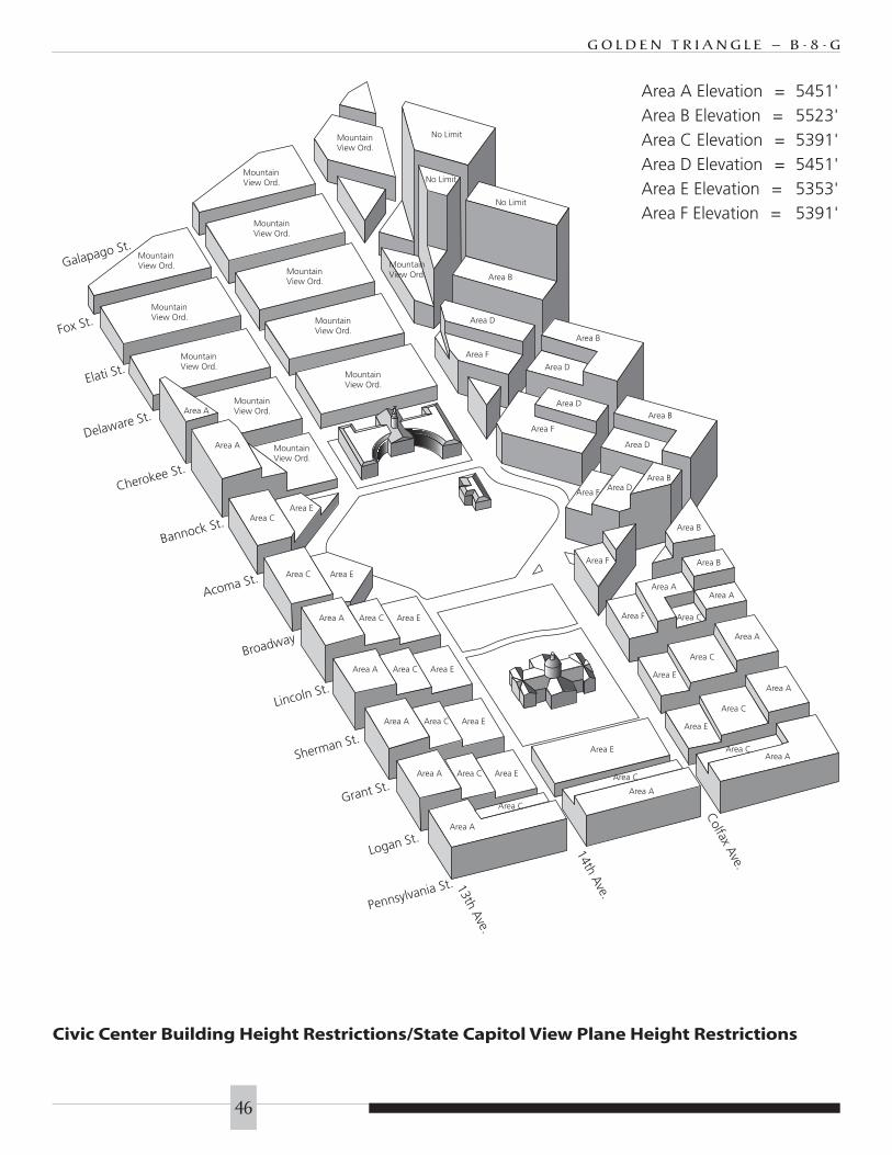
G O L D E N T R I A N G L E – B - 8 - G
46
MountainView Ord.
MountainView Ord.
MountainView Ord.
MountainView Ord.
MountainView Ord.
MountainView Ord.
MountainView Ord.
MountainView Ord.
MountainView Ord.
MountainView Ord.
Area A
Area A
Area A Elevation = 5451'Area B Elevation = 5523'Area C Elevation = 5391'Area D Elevation = 5451'Area E Elevation = 5353'Area F Elevation = 5391'
Logan St.
Pennsylvania St.
Grant St.
Sherman St.
Lincoln St.
Acoma St.
Bannock St.
Cherokee St.
Delaware St.
Elati St.
Fox St.
Galapago St.
Broadway
Area CArea E
Area C Area E
Area A Area C Area E
Area A Area C Area E
Area A Area C Area E
Area A Area C Area E
Area E
Area C
Area A
MountainView Ord.
No Limit
No Limit
MountainView Ord.
No Limit
Area B
Area D
Area F
Area B
Area D
Area D
Area F
Area C
Area A
Area B
Area D
Area DArea B
Area F
Area F
Area B
Area B
Area AArea A
Area CArea F
Area A
Area C
Area E
Area A
Area C
Area E
Area AArea C
13th Ave.
14th Ave.
Colfax Ave.
Civic Center Building Height Restrictions/State Capitol View Plane Height Restrictions

U R B A N D E S I G N S TA N D A R D S A N D G U I D E L I N E S
47
AURARIAPARKWAY
COLFAX AVE.
LIN
CO
LN S
T.
LOG
AN
ST.
BR
OA
DW
AY
ARAPAHOE S
T.
TREM
ONT PL.
GLENARM
PL.
WEL
TON ST
.
15TH ST.14TH ST.13TH ST.
16TH ST.
STOUT S
T.
CALIFORNIA
ST.
SPEER BLVD.
SAN
TA F
E D
R.
14TH AVE.
7TH
ST.
KA
LAM
ATH
ST.
COURT PL.
(LOWER)
GA
LAPA
GO
BA
NN
OC
K S
T.
CH
ERO
KEE
ST.
13TH AVE.
CURTIS ST
.
MA
RIP
OSA
ST.
UM
ATI
LLA
ST.
ZUN
I ST.
BR
YA
NT
ST.
13TH AVE.
RD.
AVE.
YU
MA
WY
AN
DO
T ST
.
ST.
MO
RRIS
ON
WALNUT ST.
COLFAX AVE.
PEA
RL
ST.
PEN
NSY
LVA
NIA
ST.
GR
AN
T ST
.
SHER
MA
N S
T.
FOX
ST.
DEL
EWA
RE
ST.
AC
OM
A S
T.
ELA
TI S
T.ST.
RIO
CT.
5TH ST.
14TH AVE.
QU
IVA
S ST
.
AVE.
ST.
LIPA
N S
T.
SHO
SHO
NE
ST. O
SAG
E ST
.
PEC
OS
9TH
12TH PL.
PL.
MYRTLE
CT.
CA
NO
SA
12TH
10TH AVE.
MULBERRY PL.
ST.
VA
LLEJ
O
ST.
UM
ATI
LLA
TEJO
N S
T.
XIN
CA
ST.
PL.
12TH AVE.
ST.
CA
NO
SA C
T.
BARBERRY PL.
WAYCLAY
ALC
OTT
BARBERRY PL.
ReferencePoint5,286'
ReferencePoint5,286'5,
303'
5,30
3'5,32
0'5,
320'
5,33
7'5,
337'
5,35
4'5,
354'
5,37
1'5,
371'
5,40
5'5,
405'
5,42
2'5,
422'
5,4
39'
5,4
39'
5,38
8'5,
388'
NORTH EDGE - DENVER ART MUSEUM
NORTH EDGE - DENVER ART MUSEUM
SOUTH EDGE - 303 W. COLFAX BLDG.
SOUTH EDGE - 303 W. COLFAX BLDG.
State Capitol View Plane
(a) Adaption of map.
The attached map shall be and hereby is approved andadopted and the portion thereon indicated by shading orcrosshatching shall be and hereby is determined to be andis designated as an area necessary for the preservation of acertain panoramic view. The restrictive provisions of thisarticle shall be in full force and effect as to the portion ofthe attached map indicated by shading or crosshatching.
(b) Limitations on construction.
No part of a structure within the area on the attached mapindicated by shading or crosshatching shall be exceed anelevation of five thousand two hundred eighty-six (5,286)feet above mean sea level plus one and seven-tenths feet for
each one hundred (100) feet that the part of a structure ishorizontally distant from the reference point. Wherever astructure lies partially outside and partially inside of thearea on the attached map indicated by shading orcrosshatching, the provisions of this section shall applyonly to that part of the structure that lies within the areaindicated on the map by shading or crosshatching.
(c) Reference point.
Reference point is a point having an elevation of fivethousand two hundred eighty-six (5,286) feet above meansea level, which point is located at the midpoint of the topstep on the westerly exposure of the capitol of the state.(Code 1950, § 645.4-4)
Sec. 10-61. State Capitol Area
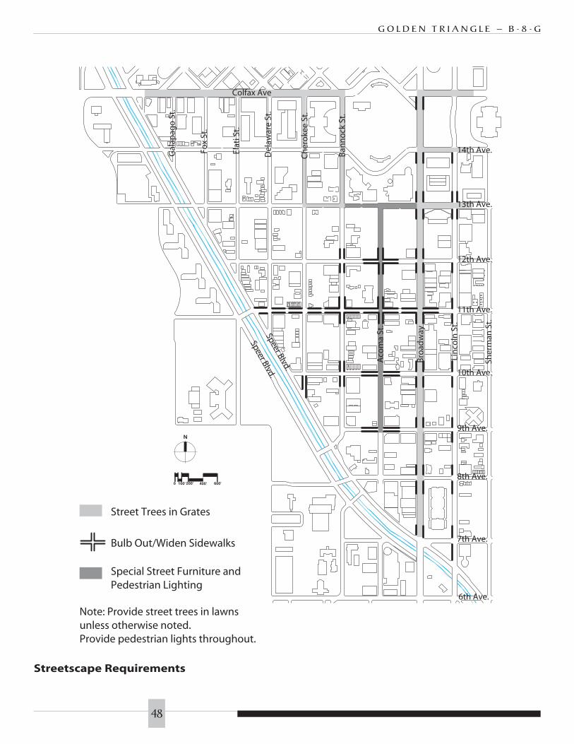
G O L D E N T R I A N G L E – B - 8 - G
48
Street Trees in Grates
Bulb Out/Widen Sidewalks
Special Street Furniture andPedestrian Lighting
Note: Provide street trees in lawnsunless otherwise noted.Provide pedestrian lights throughout.
6th Ave.
Sher
man
St.
Lin
coln
St.
Gal
apag
o S
t.
Fox
St.
Ch
ero
kee
St.
Ban
no
ck S
t.
Bro
adw
ay
Aco
ma
St.
14th Ave.
13th Ave.
12th Ave.
11th Ave.
10th Ave.
9th Ave.
8th Ave.
7th Ave.
Colfax Ave
Elat
i St.
Del
awar
e St
.
Speer Blvd.
Speer Blvd.
N
200'100'0 400' 600'
Streetscape Requirements
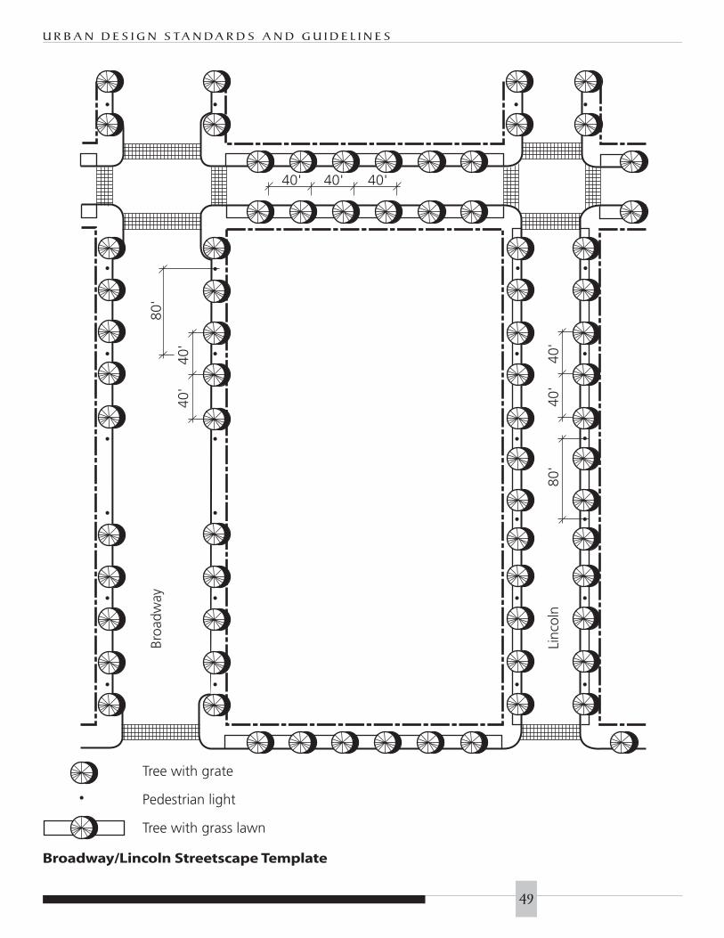
U R B A N D E S I G N S TA N D A R D S A N D G U I D E L I N E S
49
Tree with grate
Pedestrian light
Tree with grass lawn
Broa
dway
80'
40'
40'
40'
40'
80'
Linc
oln
40' 40' 40'
Broadway/Lincoln Streetscape Template
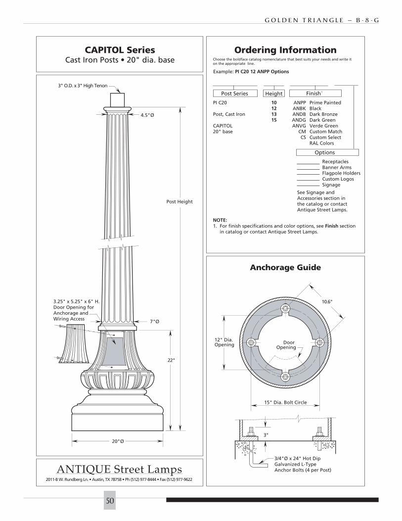
G O L D E N T R I A N G L E – B - 8 - G
50
3/4"Ø x 24" Hot DipGalvanized L-TypeAnchor Bolts (4 per Post)
3"
3" O.D. x 3" High Tenon
20"Ø
10.6"
Door Opening
12" Dia. Opening
15" Dia. Bolt Circle
22"
4.5"Ø
7"Ø
3.25" x 5.25" x 6" H.Door Opening forAnchorage andWiring Access
Post Height
ANTIQUE Street Lamps2011-B W. Rundberg Ln. • Austin, TX 78758 • Ph (512) 977-8444 • Fax (512) 977-9622
CAPITOL SeriesCast Iron Posts • 20" dia. base
Ordering Information
Anchorage Guide
Finish1Height
Options
Choose the boldface catalog nomenclature that best suits your needs and write iton the appropriate line.
ReceptaclesBanner ArmsFlagpole HoldersCustom LogosSignage
See Signage and Accessories section in the catalog or contact Antique Street Lamps.
Post Series
PI C20
Post, Cast Iron
CAPITOL20" base
NOTE:1. For finish specifications and color options, see Finish section in catalog or contact Antique Street Lamps.
ANPPANBKANDBANDGANVG
CMCS
Prime PaintedBlackDark BronzeDark GreenVerde GreenCustom MatchCustom SelectRAL Colors
10121315
Example: PI C20 12 ANPP Options

U R B A N D E S I G N S TA N D A R D S A N D G U I D E L I N E S
51
9' - 6"
12' - 0"
13' - 2"
14' - 6"
ANTIQUE Street Lamps
CAPITOL SeriesCast Iron Posts
20" dia. base
Specifications
DescriptionThe lighting post shall be all cast ironconstruction, massively tapered witha deep, 16-flute pattern on the shaftand base. The post shall be AntiqueStreet Lamps’ catalog numberPI C20 XX finish.
MaterialsThe post material shall be ASTM A48, Class 30 cast iron, formed true to the pattern with complete detail. All exposed hardware shall be tamperresistant stainless steel. Anchor boltsto be completely hot dip galvanized.Partially galvanized bolts are not acceptable.
DimensionsThe post shall be X' - XX" in height with a 20" diameter base. The post shall 7" diameter at the top of the base to 4.5" diameter at the post top.An integral 3" O.D. x 3" tenon shallbe provided at the top for luminairemounting. The post top shall include a transitional donut between the fluted shaft and the tenon.
InstallationThe post shall be provided with four3/4" diameter by 24" long, L-typeanchor bolts to be installed on a 15"diameter bolt circle. A door shall beprovided in the base for anchorageand wiring access. A grounding screwshall be provided inside the base opposite the door.
For finish specifications and coloroptions, see “Finish” section in catalog.
PI C20 10 finishPI C20 12 finishPI C20 13 finishPI C20 15 finish
2011-B W. Rundberg Ln. • Austin, TX 78758Ph (512) 977-8444 • Fax (512) 977-9622
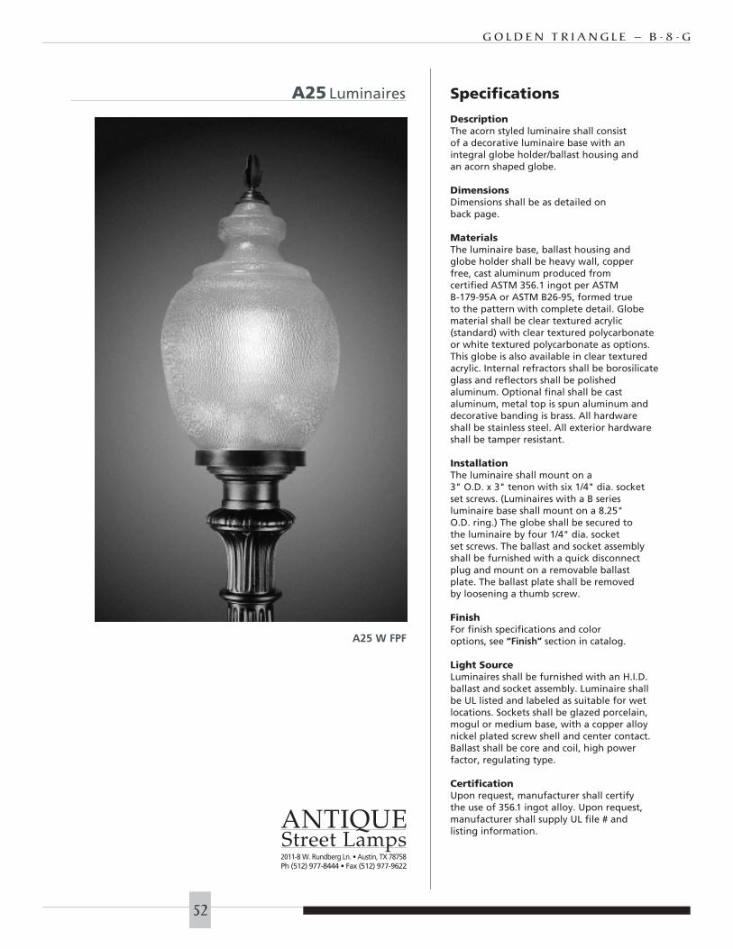
G O L D E N T R I A N G L E – B - 8 - G
52
A25 Luminaires Specifications
DescriptionThe acorn styled luminaire shall consistof a decorative luminaire base with anintegral globe holder/ballast housing andan acorn shaped globe.
DimensionsDimensions shall be as detailed on back page.
MaterialsThe luminaire base, ballast housing andglobe holder shall be heavy wall, copperfree, cast aluminum produced from certified ASTM 356.1 ingot per ASTM B-179-95A or ASTM B26-95, formed true to the pattern with complete detail. Globematerial shall be clear textured acrylic(standard) with clear textured polycarbonateor white textured polycarbonate as options.This globe is also available in clear textured acrylic. Internal refractors shall be borosilicateglass and reflectors shall be polished aluminum. Optional final shall be castaluminum, metal top is spun aluminum anddecorative banding is brass. All hardwareshall be stainless steel. All exterior hardwareshall be tamper resistant.
InstallationThe luminaire shall mount on a 3" O.D. x 3" tenon with six 1/4" dia. socketset screws. (Luminaires with a B series luminaire base shall mount on a 8.25"O.D. ring.) The globe shall be secured tothe luminaire by four 1/4" dia. socketset screws. The ballast and socket assemblyshall be furnished with a quick disconnectplug and mount on a removable ballast plate. The ballast plate shall be removedby loosening a thumb screw.
FinishFor finish specifications and coloroptions, see “Finish” section in catalog.
Light SourceLuminaires shall be furnished with an H.I.D.ballast and socket assembly. Luminaire shallbe UL listed and labeled as suitable for wetlocations. Sockets shall be glazed porcelain,mogul or medium base, with a copper alloynickel plated screw shell and center contact.Ballast shall be core and coil, high powerfactor, regulating type.
CertificationUpon request, manufacturer shall certifythe use of 356.1 ingot alloy. Upon request, manufacturer shall supply UL file # andlisting information.
A25 W FPF
ANTIQUEStreet Lamps2011-B W. Rundberg Ln. • Austin, TX 78758Ph (512) 977-8444 • Fax (512) 977-9622
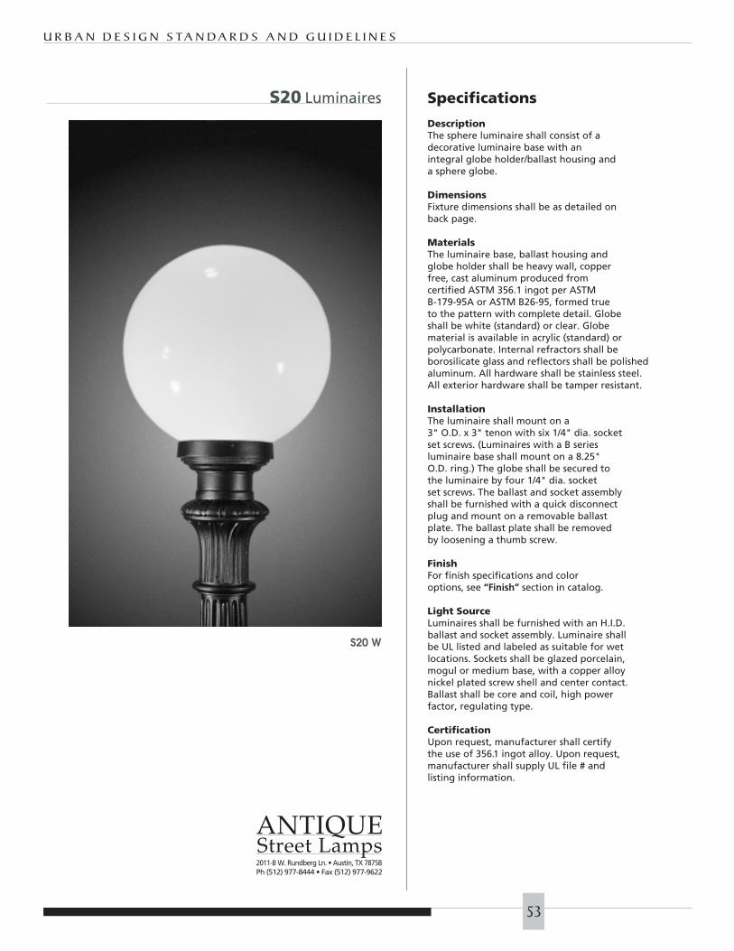
U R B A N D E S I G N S TA N D A R D S A N D G U I D E L I N E S
53
S20 Luminaires
S20 W
Specifications
DescriptionThe sphere luminaire shall consist of a decorative luminaire base with anintegral globe holder/ballast housing anda sphere globe.
DimensionsFixture dimensions shall be as detailed on back page.
MaterialsThe luminaire base, ballast housing andglobe holder shall be heavy wall, copperfree, cast aluminum produced from certified ASTM 356.1 ingot per ASTM B-179-95A or ASTM B26-95, formed true to the pattern with complete detail. Globeshall be white (standard) or clear. Globematerial is available in acrylic (standard) orpolycarbonate. Internal refractors shall be borosilicate glass and reflectors shall be polished aluminum. All hardware shall be stainless steel. All exterior hardware shall be tamper resistant.
InstallationThe luminaire shall mount on a 3" O.D. x 3" tenon with six 1/4" dia. socketset screws. (Luminaires with a B series luminaire base shall mount on a 8.25"O.D. ring.) The globe shall be secured tothe luminaire by four 1/4" dia. socketset screws. The ballast and socket assemblyshall be furnished with a quick disconnectplug and mount on a removable ballast plate. The ballast plate shall be removedby loosening a thumb screw.
FinishFor finish specifications and coloroptions, see “Finish” section in catalog.
Light SourceLuminaires shall be furnished with an H.I.D.ballast and socket assembly. Luminaire shallbe UL listed and labeled as suitable for wetlocations. Sockets shall be glazed porcelain,mogul or medium base, with a copper alloynickel plated screw shell and center contact.Ballast shall be core and coil, high powerfactor, regulating type.
CertificationUpon request, manufacturer shall certifythe use of 356.1 ingot alloy. Upon request, manufacturer shall supply UL file # andlisting information.
ANTIQUEStreet Lamps2011-B W. Rundberg Ln. • Austin, TX 78758Ph (512) 977-8444 • Fax (512) 977-9622
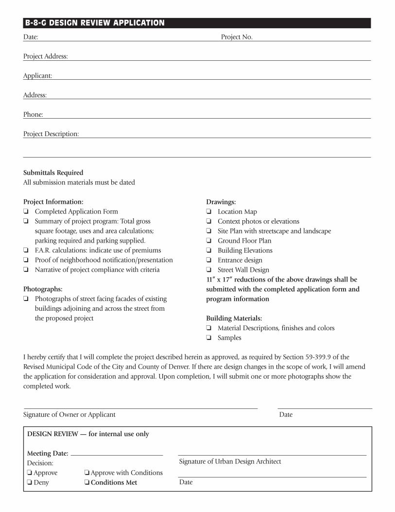
B-8-G DESIGN REVIEW APPLICATION
Date: Project No.
Project Address:
Applicant:
Address:
Phone:
Project Description:
Submittals RequiredAll submission materials must be dated
Project Information:❏ Completed Application Form❏ Summary of project program: Total gross
square footage, uses and area calculations;parking required and parking supplied.
❏ F.A.R. calculations: indicate use of premiums❏ Proof of neighborhood notification/presentation❏ Narrative of project compliance with criteria
Photographs:❏ Photographs of street facing facades of existing
buildings adjoining and across the street fromthe proposed project
I hereby certify that I will complete the project described herein as approved, as required by Section 59-399.9 of theRevised Municipal Code of the City and County of Denver. If there are design changes in the scope of work, I will amendthe application for consideration and approval. Upon completion, I will submit one or more photographs show thecompleted work.
Signature of Owner or Applicant Date
DESIGN REVIEW — for internal use only
Meeting Date:Decision: ❏ Approve ❏ Approve with Conditions❏ Deny ❏ Conditions Met
Drawings:❏ Location Map❏ Context photos or elevations❏ Site Plan with streetscape and landscape❏ Ground Floor Plan❏ Building Elevations❏ Entrance design❏ Street Wall Design11” x 17” reductions of the above drawings shall besubmitted with the completed application form andprogram information
Building Materials:❏ Material Descriptions, finishes and colors❏ Samples
Signature of Urban Design Architect
Date