design for additive manufacturing · design for additive manufacturing 103-r23-dfmrev2-20jun16 v2...
TRANSCRIPT

131 Citation Drive, Units 17 & 18, Concord, ON, Canada, L4K-2R3, Ph: 905 738 0410 www.additivemet.com
Design for Additive Metal Manufacturing
Additive Metal Manufacturing Inc.
Concord, ON, Canada

Design for Additive Manufacturing
103-R23-DFMRev2-20Jun16 V2 Page 1 of 14
Contents 1 Introduction .......................................................................................................................................... 2
2 Design for Additive Manufacturing (DFAM) ......................................................................................... 2
2.1 Design for minimum impact of DMLS geometrical constraints .................................................... 3
2.1.1 Accuracy ................................................................................................................................ 3
2.1.2 Surface Finish ........................................................................................................................ 4
2.1.3 Holes and Passages ............................................................................................................... 6
2.1.4 Wall Thickness ....................................................................................................................... 9
2.1.5 Over-hangs .......................................................................................................................... 10
2.1.6 Threads ................................................................................................................................ 11
3 Appendix I – Maraging Steel (MS1) for DMLS ..................................................................................... 12

Design for Additive Manufacturing
103-R23-DFMRev2-20Jun16 V2 Page 2 of 14
1 Introduction Additive technology especially in metals could lead us to produce real application parts which were
impossible to produce using conventional processes. Light weighted components with intricate lattice
structures, tools with conformal cooling channels for injection molding and die casting processes, and
customized implants for the medical industry are some examples.
In order to take maximum advantage from the capabilities of additive metal technology in the most
economical way, engineers should learn how to design for this technology by following its principles.
The design for additive metal manufacturing (DFAM) concept refers to the act of integrating product
design and additive manufacturing principles into one activity.
This report introduces the designers to some of the DFAM rules of the additive metal technology by
going thorough the details of its capabilities and constraints.
2 Design for Additive Manufacturing (DFAM) In designing for additive manufacturing the following rules are usually followed:
• Design for minimum impact of DMLS geometrical constraints
• Design for minimum support material
• Design for minimum post-processing

Design for Additive Manufacturing
103-R23-DFMRev2-20Jun16 V2 Page 3 of 14
The role of the current document is to introduce the principles in design for minimum impact of DMLS
geometrical constraints.
2.1 Design for minimum impact of DMLS geometrical constraints Some general rules to be considered in the design for additive metal manufacturing:
2.1.1 Accuracy In additive metal manufacturing as parts are generated from metal powder, the surface roughness and
the geometrical accuracy lies within the range of the powder grain size. Part accuracy depends on the
powder material used. To achieve accuracy, the machine needs to be fine-tuned.
Tight tolerances are usually achieved by post machining. The following recommendations regarding
post-machining have been made by EOS:
• 0.015”- 0.030” additional stock on milled and turned surfaces
• 0.005” additional stock per side for reamed surfaces
• 0.004” - 0.008” larger diameter for hole / passages to remain as built
• 0.002” – 0.004” for polishing
Electron Optical Systems (EOS) Inc. provides the data in Table 1 as the best achievable accuracy using
their equipment:
Material Accuracy
MaragingSteel MS1 small parts (< 80×80 mm) ±20µm or ±0.8×10⁻³ inch large parts ±50µm or ±2×10⁻³ inch
Table 1

Design for Additive Manufacturing
103-R23-DFMRev2-20Jun16 V2 Page 4 of 14
2.1.2 Surface Finish In additive metal manufacturing due to the layer-wise building, the roughness of each surface strongly
depends on its orientation in the building platform. Consider the cube in Figure 1. Depending on how
this cube is orientated in the building platform, the surface normal is different for each face as will be
the quality of the faces built by additive metal technology.
Cube surface roughness – orientation 1
Cube surface roughness – orientation 2 Figure 1; Surface roughness in different orientations

Design for Additive Manufacturing
103-R23-DFMRev2-20Jun16 V2 Page 5 of 14
Based on the experimental studies it has been proved that the horizontal, vertical, and up-facing
surfaces have the best surface finish quality and down-facing surfaces the worst.
In terms of the down-facing surfaces, these can be built without support approximately above 30°-35°.
The quality of these surfaces increase as the orientation angle increases. This is illustrated in Figure 2.
CAD Model
DMLS part
Figure 2; Roughness on the down facing surface

Design for Additive Manufacturing
103-R23-DFMRev2-20Jun16 V2 Page 6 of 14
Electron Optical Systems (EOS) Inc. provides the data in Table 2 as the best achievable surface finish
using their equipment:
Material Condition Surface Roughness
Maraging Steel MS1
As manufactured (build) Ra 12 -18 μm, Rz 60 – 80 μm
Ra 0.47 – 0.71 x 10-³ inch, Rz 2.36 – 3.15 x 10-³ inch
After shot peening Ra 4 - 6.5 μm, Rz 20 - 50 μm Ra 0.16 – 0.26 x 10-³ inch, Rz 0.78 – 1.97 x 10-³ inch
After polishing Rz up to < 0.5 μm
Rz up to < 0.02 x 10-³ inch (can be very finely polished)
Table 2
Recommendations:
It is recommended that designers avoid down-facing and tilted surfaces as much as possible when
designing for additive metal manufacturing.
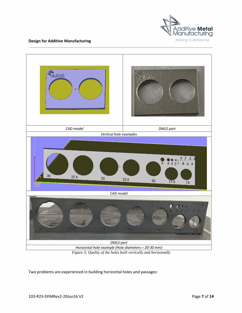
2.1.3 Holes and Passages In additive metal manufacturing it has been generally proved that vertical holes and passages a better
quality hole than horizontal ones. Figure 3 shows holes built vertically in comparison to those built
horizontally.
Design for Additive Manufacturing
103-R23-DFMRev2-20Jun16 V2 Page 7 of 14
CAD model DMLS part
Vertical hole examples
CAD model
DMLS part
Horizontal hole example (Hole diameters = 20-30 mm) Figure 3; Quality of the holes built vertically and horizontally
Two problems are experienced in building horizontal holes and passages:

Design for Additive Manufacturing
103-R23-DFMRev2-20Jun16 V2 Page 8 of 14
• Sagging: Sagging refers to the fact that the metal powders are generally self-supporting when
being built upward and over 40 to 45 degree angles. When the building process reaches the top
of the circular cross section, the angle of the building direction is below the mentioned critical
angle. Powders are not self-supporting and signs of sagging is observed.
• Burning: As the building process reaches the top of the circular cross-section, the surface area
on top of which melting is occurring is decreased and that results in a reduction of the rate of
heat transfer. This results in burning being observed in this area.
Due to sagging and burning, the top of the circular cross sections being built in a horizontal direction
generally have rough surfaces. This is illustrated in Figure 4.
DMLS part
Figure 4; Holes built in a horizontal direction
Recommendations:
It is recommended that:
• Avoid horizontal holes and passages with circular cross-sections

Design for Additive Manufacturing
103-R23-DFMRev2-20Jun16 V2 Page 9 of 14
• If not avoidable, the circular geometry of the cross-section should be modified to pear or cone
shape:
CAD model
DMLS part
Figure 5; Modified holes built in horizontal direction
• If there is no freedom to change the design, the horizontal holes can be still be built, but their
top down facing surfaces need to be supported if their size is larger than 10 mm. However, it
should be noted that supporting the long horizontal holes and passages such as in conformal
cooling channels in molds and tool inserts will be problematic as support removal will not be an
easy task and in fact, is almost impossible:
2.1.4 Wall Thickness The thickness of the wall that can be printed without support has been reported to be highly material
dependent. The minimum wall thickness also depends on the offset of the laser beam (beam diameter
plus the size of the curing zone). Very thin wall sections -or placing a thin section against a thick section -
may result in significant distortion due to the very high temperatures involved in the process.

Design for Additive Manufacturing
103-R23-DFMRev2-20Jun16 V2 Page 10 of 14
CAD Model DMLS Part
Figure 6; Building thin walls in additive metal manufacturing
Electron Optical Systems (EOS) Inc. provides the data in Table 3 as the minimum wall thickness that can
be built without any support. Walls with smaller thickness can be printed but they will need support.
Material Minimum Wall Thickness
Maraging Steel MS1 approx. 0.4 - 0.6 mm approx. 0.016 - 0.024 inch
Table 3
Recommendations:
It is recommended to:
• Keep the minimum wall thickness as 0.4 mm.
2.1.5 Over-hangs Any feature on a part that has a down-facing surface is defined as the over-hang. Over-hangs can be
built without any support material if their orientation angle is above 35°. If they are below 35° they need
to be supported.

Design for Additive Manufacturing
103-R23-DFMRev2-20Jun16 V2 Page 11 of 14
Illustration of over-hangs in CAD model and correponsing DMLS part Figure 7; Over-hangs in additive metal technology
Recommendations:
• Avoid over-hangs in the design as much as possible
• Modify the design to optimize the geometry of the over-hang
2.1.6 Threads Threads are not a good candidate for additive manufacturing. They generally consists of down-facing
surfaces with an orientation angle below 35°. However, if they are to be manufactured based on DMLS,
the following points are recommended:

Design for Additive Manufacturing
103-R23-DFMRev2-20Jun16 V2 Page 12 of 14
Recommendations:
• Place them in a vertical direction
• Standard threads are usually chased with a tap
• Small threads are usually recommended to be removed from the CAD file and post-machined
Threads (courtesy of EOS)
Figure 8; Threads in additive metal technology
3 Appendix I – Maraging Steel (MS1) for DMLS The name Maraging comes from "mar"tensite + "aging" [treatment].
• Parts built in EOS Maraging Steel MS1 have a chemical composition corresponding to US
classification18% Ni Maraging 300, European 1.2709 and German X3NiCoMoTi 18-9-5
• It is a low-carbon steel with martensitic structure
• Yield strength; as built is 1000±100 MPa and after age hardening is 1990±100 MPa
• Tensile strength; as built is 1100±100 MPa and after age hardening is 2050±100 MPa
• It is hard and tough; hardness as built is 33-37 HRS and after age hardening 50-56 HRC
• It has a very low shrinkage factor
• There is no difference between MS1 and the conventional 1.2709

Design for Additive Manufacturing
103-R23-DFMRev2-20Jun16 V2 Page 13 of 14
• This material is best suited to this process (best possible results) and fulfils all tooling
requirements
• The maximum operating temperature for MS1 is 400°C (750°F). The majority of plastic materials
are injected at approximately 280°C and for this reason the factor temperature is not critical at
all for MS1.
• In both as-built and age-hardened states the parts can be machined, spark-eroded (EDM),
welded, micro shot-peened, polished and coated if required. Due to the layer-wise building
method, the parts have a certain anisotropy, this can be reduced or removed by appropriate
heat treatment
• Porosity is not an issue for the MS1 material. The process allows complete control of the
porosity values and a mold relative density of nearly 100 %
• After polishing it is possible to achieve roughness values of “Ra (ISO) up to < 0.5 µm” and “Rz
(DIN) up to < 0.02 mm”