design, construction and characterization of a small … · design, construction and...
TRANSCRIPT

Copyright 2012 Julian Leland
1
Design, Construction and Characterization of a Small-Scale, “Self-Replicating” Machine Tool
Julian Leland – [email protected] Swarthmore College, Department of Engineering, Spring 2012
Faculty Advisor: Prof. Faruq Siddiqui
Abstract: A small-scale milling machine was designed. This machine was intended to be “self-replicating,” in the sense that a user equipped with an existing copy of the machine as well as basic hand and handheld power tools could reproduce all parts used in the machine’s construction not easily available from large commercial retailers. The machine was constructed, and its accuracy was characterized using ISO standards 1984-1982 and 230-1 [1] [2]. Although the machine will require significant further work before it is cost- and performance-competitive with existing alternatives, this project has made some progress towards both the development of a “self-replicating” machine as well as a methodology for characterizing such machines.
I. Introduction
In recent years, the development of small, affordable rapid fabrication tools such as 3D printers have made the concept of “desktop manufacturing” a popular topic, even outside of the hobbyist and maker communities. Increasingly, the low cost and relative simplicity of these machines is making them accessible to educators, small businesses and other users who previously would have never considered integrating a computer-controlled machine into their work. Additionally, the concept of self-replication – that the machine can be used to create all non-standard parts (e.g. parts not easily purchased from industrial suppliers) involved in its construction – is becoming more fundamental to this new breed of tools, with users taking advantage of the self-replicating nature of some machines to increase the dissemination (and popularity) of these new tools by simply building more.
Currently, most rapid fabrication tools currently available fall into one of three classes:
1. Additive manufacturing tools, such as the MakerBot or RepRap 3D printers
2. Non-contact subtractive manufacturing tools, such as the PlasmaCAM CNC plasma cutter
3. Routers, such as the ShopBot Desktop, Zenbot, or Probotix Fireball V4
One class of machine that has largely been overlooked is the traditional milling machine. These machines are subtractive manufacturing tools like routers, but are built much more heavily to allow the working of metals at a (reasonably) rapid rate while still maintaining a high degree of cut precision. Historically, milling machines have been large, heavy pieces of equipment. Small milling machines have always been available, and are currently produced by a number of manufacturers including Sherline, Taig, Harbor Freight and LittleMachineShop. However, these machines are often expensive, limited in their functionality, and frequently of variable quality. Finally, they are not capable of self-replication: most of the components in these machines are either too large for the machine to produce, or require advanced machining processes such as grinding, scraping or heat-treating to be usable.
The goal of this project was to work towards filling this gap, by designing and constructing a 3-axis machine tool, primarily intended for milling use, which would able to mill basic materials including mild steel, and was capable of creating all non-standard parts involved in its construction. The machine was intended to be small (≤ 250 lbs., work volume of roughly 6” x 6” x 6”), constructed exclusively from widely available components and self-produced components without requiring any of

Copyright 2012 Julian Leland
2
the aforementioned advanced machining processes, and comparable in cost to its competitors ($500-$700).
II. Design
The design of this machine tool was divided into four discrete tasks. First, the problem that this project attempts to address was fully defined; the machine’s function and basic specifications were outlined, and basic performance goals were set. This data was then used to develop design parameters for the machine, including expected maximum cutting force and driving frequencies affecting the machine. Second, the machine’s frame was designed. Primary concerns for this section of the design process included manufacturability, static and dynamic performance, and cost. Third, the machine’s linear motion systems, including X- and Y-axis bearings and motion components, were specified and designed. Finally, the machine’s spindle unit and motor were selected and implemented. Because of the necessary interactions between these systems, design of the three major sub-systems was pursued in parallel, rather than serially.
A. Definition of Function and Specifications
A basic outline of the machine’s function and specifications was developed, based on Slocum’s suggested design plan for a machine tool [3]. Among the characteristics defined during this process were:
• Geometry and Frame Design: The machine was required to be relatively small, weighing around 250 lbs. and taking up a total volume of no more than 36” x 36” x 36”. Its work volume was specified to be 6” x 6” x 6”. Because of this relatively small work volume, the machine was also required to allow limited-mobility machining of parts larger than 6” x 6” x 6”, for example, by allowing parts to protrude from the machine’s frame during machining operations. No specific frame geometry was specified for the machine. This was done primarily to permit the
development of alternative frame designs. The traditional C-frame design used in most small milling machines is relatively flexible; all frame elements between the cutting tool and the workpiece are cantilevered, requiring comparatively massive frame elements for a given degree of stiffness. Since the limited work volume of this machine precluded the use of large frame components, the required frame stiffness would need to be achieved through a smaller, more enclosed frame design.
• Machine Type and Kinematics: The machine was intended for use as a vertical milling machine (as opposed to a turning center or grinding machine), using singly-supported tools. No specific translation system was specified for the machine, to allow non-Cartesian systems to be implemented.
• Materials Selection: The materials used in the construction of this machine were required to be, in order of importance: 1) inexpensive, 2) easily rough-machined (for example, sawed to size using hand tools) or otherwise easily worked, and 3) easily available, ideally from industrial distributors such as MSC or McMaster-Carr.
• Production and Assembly: In keeping with the requirement that reproduction of the machine be feasible for the average hobbyist, a number of constraints were placed on the machine’s production and assembly. Allowed production methods were limited to what the machine itself could theoretically perform (precision milling and drilling), and what a competent user could produce using basic hand tools such as hacksaws, power drills, files, and the like. Precision required in parts was required not to exceed that achievable by the machine: truly high-precision parts (for example, linear ways) were to be sourced from major manufacturers, and no grinding or significant scraping was to be permitted. Total tooling costs were to be kept as low as possible, with a minimum number of distinct tooling setups used to create the entire machine.

Copyright 2012 Julian Leland
3
Finally, assembly was placed under the same restrictions as production, with no tools or processes that the average user would not be expected to have access to being allowed (for example, press-fitting or welding).
• Cost: The cost of the machine was stipulated to be between $500 and $700, excluding CNC components.
With these characteristics defined, a number of quantitative performance goals were also defined.
• Maximum Cutting Force Determination: The first parameter needed before design could begin in earnest was the maximum cutting force that the machine would reasonably be subject to. A spreadsheet intended for calculating cutting force and machine power requirements was developed, using a synthesis of similar derivations from Machinery’s Handbook as well as a variety of other sources [4]. The maximum expected cutting force was found to be 138 lbf (614 N). This was found for a .2” x .375” cut at 2400 RPM and a feed of .001” per tooth, using a .375” end mill, in AISI 1018 CR steel. A factor of safety of 1.5 was applied, bringing the maximum cutting force to 200 lbf (890 N), which was used throughout the design process as the maximum expected load.
• Spindle Power Capacity: The maximum cutting force calculations developed above indicated a maximum required spindle power of 1.2 HP (895 W).i
• Maximum and Minimum Translation Rates: The minimum translation rate required from the machine was found during the calculation of the maximum cutting force; based on speed and feed tables in Machinery’s Handbook, it was found to be 5.19 in/min, or .086 in/sec. This rate was specified for design purposes rather than as an actual performance parameter, to ensure that the machine was able to execute smooth translations at this rate without jerking or “cogging” when CNC control is eventually implemented. Similarly, a maximum translation rate of 3 in/sec was also
specified as a design parameter, with the intent that the machine should be able to fully transverse its work volume in under 2 seconds.
• Axis Positioning Accuracy: Axis positioning accuracy was specified extremely generally, so as to permit non-Cartesian translation systems to be used. Specifications were that the machine should be able to position a part to within ± .0005” anywhere within its work volume, in any cardinal direction; that the repeatability of positioning should be ± .0005”; and that the resolution of positioning should be at least .0005”. Like the maximum and minimum translation rates, these specifications were primarily intended to be design goals rather than actual measurable performance goals.
• Cutting Accuracy: The machine was specified to be able to perform a .125” x .1” full-width cut in mild steel without experiencing total error motion greater than .001”. This cut was expected to produce a maximum cutting force of 86 lbf (383 N) by the cutting force spreadsheet, although other cutting force calculators have predicted a significantly lower value. Unlike the positioning accuracy and translation rate specifications, this metric was intended both as a design parameter and a measurable performance goal.
B. Frame Design
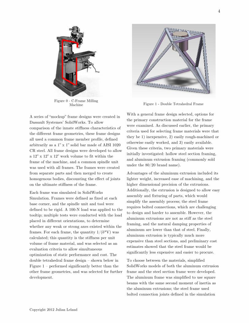
Design of the frame focused primarily on maximizing the frame’s stiffness. As mentioned above, most commercial machines use a C-frame design, like that used on the traditional “Bridgeport-style” vertical mill shown in Figure 0. This design maximizes operator accessibility at the expense of rigidity, since all frame components between the cutting tool and the workpiece are cantilevered. Because the machine developed by this project is intended for eventual use as a CNC machining center, the accessibility requirements of the machine were reduced, creating an opportunity for increasing the stiffness of the frame through the use of closed frame designs.
Copyright 2012 Julian Leland
4
A series of “mockup” frame designs were created in Dassault Systemes’ SolidWorks. To allow comparison of the innate stiffness characteristics of the different frame geometries, these frame designs all used a common frame member profile, defined arbitrarily as a 1” x 1” solid bar made of AISI 1020 CR steel. All frame designs were developed to allow a 12” x 12” x 12” work volume to fit within the frame of the machine, and a common spindle unit was used with all frames. The frames were created from separate parts and then merged to create homogenous bodies, discounting the effect of joints on the ultimate stiffness of the frame.
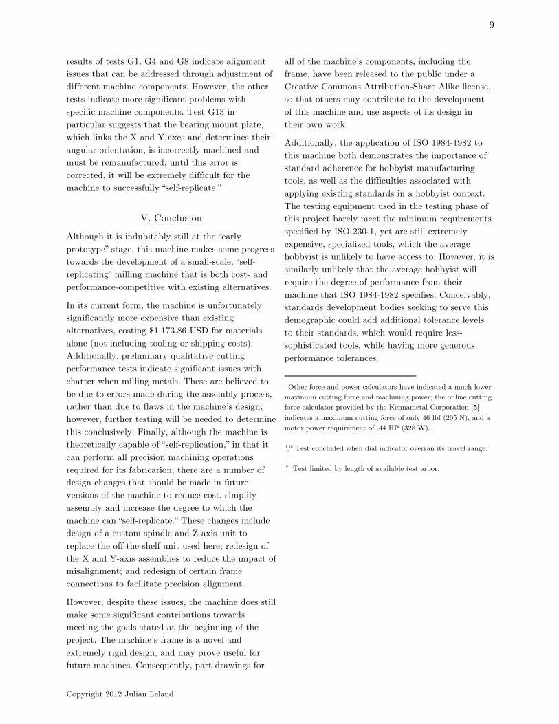
Each frame was simulated in SolidWorks Simulation. Frames were defined as fixed at each base corner, and the spindle unit and tool were defined to be rigid. A 100-N load was applied to the tooltip; multiple tests were conducted with the load placed in different orientations, to determine whether any weak or strong axes existed within the frames. For each frame, the quantity 1/(δ*V) was calculated; this quantity is the stiffness per unit volume of frame material, and was selected as an evaluation criteria to allow simultaneous optimization of static performance and cost. The double tetrahedral frame design – shown below in Figure 1 – performed significantly better than the other frame geometries, and was selected for further development.
Figure 1 - Double Tetrahedral Frame
With a general frame design selected, options for the primary construction material for the frame were examined. As discussed earlier, the primary criteria used for selecting frame materials were that they be 1) inexpensive, 2) easily rough-machined or otherwise easily worked, and 3) easily available. Given these criteria, two primary materials were initially investigated: hollow steel section framing, and aluminum extrusion framing (commonly sold under the 80/20 brand name).
Advantages of the aluminum extrusion included its lighter weight, increased ease of machining, and the higher dimensional precision of the extrusions. Additionally, the extrusion is designed to allow easy assembly and fixturing of parts, which would simplify the assembly process; the steel frame requires bolted connections, which are challenging to design and harder to assemble. However, the aluminum extrusions are not as stiff as the steel framing, and the natural damping properties of aluminum are lower than that of steel. Finally, aluminum extrusion is typically much more expensive than steel sections, and preliminary cost estimates showed that the steel frame would be significantly less expensive and easier to procure.
To choose between the materials, simplified SolidWorks models of both the aluminum extrusion frame and the steel section frame were developed. The aluminum frame was simplified to use square beams with the same second moment of inertia as the aluminum extrusions; the steel frame used bolted connection joints defined in the simulation
Figure 0 - C-Frame Milling Machine

Copyright 2012 Julian Leland
5
process, rather than incorporating actual models of the bolted connections. In both frames, a mockup spindle was used; it was defined as rigid for the purposes of simulation. A series of simulations, including static deflection, dynamic behavior and thermal expansion, were conducted on each frame design.
• Static Performance: A simulated load of 67 lbf (300 N) was applied at the tooltip. In both frames, areas at the corners of the bases of the frames were defined as fixed. Under these loading conditions, the aluminum frame experienced a maximum deflection of .0012”, while the steel frame experienced a maximum deflection of .0004”. Additionally, a second test was run with the steel frame defined as universally bonded as opposed to having bolted connections. For this test, the maximum deflection experienced was .00006”. Because of the author’s unfamiliarity with the use of bolted connections in SolidWorks, it is currently unclear which more accurately represents the machine’s performance. However, since the aluminum frame had been defined as universally bonded in the original test, it was accepted that the steel frame was demonstrating greater static performance.
• Dynamic Performance: The dynamic performance of the frame designs was examined using both analytical and finite-element methods. Unfortunately, significant differences between the results produced by these methods led to their being discarded; the steel frame was chosen to have superior dynamic performance as a function of its weight and the greater natural damping characteristics of the steel.
• Thermal Performance: Finally, the thermal performance of the designs was analyzed, using a SolidWorks ambient temperature simulation. The steel frame again performed significantly better, deforming both at a slower rate and to a lesser degree than the aluminum frame. In both simulations, the majority of the thermal expansion occurred in the Z direction: the symmetry of the double tetrahedral frame
design makes it relatively resistant to thermal deformation affecting cut accuracy.
In light of these results, the steel frame design was deemed superior, and was selected for use.
C. Linear Motion System Design
With the design of the frame completed, the design of the linear motion systems for the X, Y and Z axes was addressed. Early on in the project, alternative linear motion systems incorporating novel mixed linear and rotary motion systems were investigated. However, it quickly became clear that the additional complexity required by these systems was not justified by the performance gains they would yield, and simple stacked linear motion systems were selected.
The first step in developing the linear motion systems was to determine the maximum performance that would be required of those systems. A spreadsheet template was developed that approximates the reaction forces and moments on bearings produced by a load anywhere in 3-space, for 4-, 3- and 2-bearing carriages. This template is developed from a derivation originally formulated by Slocum [3] for approximating the loads experienced by bearings in a 4-bearing carriage. The author expanded this further to include the 3- and 2-bearing cases using the same principles.
Using this spreadsheet, bearing loads were calculated for 4-, 3-, and 2-bearing stages, for 200 lbf loads applied in the X, Y and Z directions. In all trials, the point of application of the force was defined to be at the center of the work volume, while the stage was defined at the location that would produce the greatest stresses on the bearings (typically, at the extreme end of its travel). From these tests, the 3-bearing stage configuration was determined to be the most cost-effective, yielding only slightly higher loads than a 4-bearing configuration and avoiding the high moments produced in a 2-bearing configuration, while still reducing the cost of the system significantly. Maximum design loads were found to be ± 250 lbf in the X and Y directions, and ± 600 lbf in the Z direction.

Copyright 2012 Julian Leland
6
With these bearing loads determined, a bearing system was selected. Early on, it was decided that because of time constraints and manufacturing limitations, linear motion systems for the X- and Y-axis would be purchased off-the-shelf, rather than being fabricated. A variety of bearing systems were investigated, including wheel-and-rail systems, sliding bearings, ball bearing sleeves with linear shafting, and recirculating ball-bearing block systems. After literature reviews and discussions with bearing system manufacturers, a 15mm recirculating ball-bearing block system was selected. These systems are extremely stiff, and impart very little running resistance. Additionally, these are capable of handling impact loads, and will continue to slide smoothly under intermittent loading – an important characteristic. Unfortunately, these bearings are also extremely expensive.
In addition to the linear bearings, a linear actuation system was specified and designed. The primary driving factor in the design of the linear actuation system was the fact that the machine is eventually intended for CNC control, but would initially be manually operated. Consequently, the linear actuation system would need to be both usable by a human operator, but also compatible with eventual CNC control. A system based around the 3/8” – 10 Acme screw thread standard was selected. Acme screws, which have been used for decades as power- and motion-transmission screws, are easily available, and much less expensive than ball screw systems. The 10 TPI formfactor also allows for easy control by a human operator: one turn of the screw corresponds to a total motion of .1”, which is a convenient measurement. The leadscrews were singly supported by two angular-contact ball bearings in a DF configuration, which allows for slight angular misalignment of the screws while still providing adequate axial stiffness.
D. Spindle & Power Systems Design
The last major design task addressed was the selection of the spindle and drive motor. Early on in the project, a variety of options for spindle units were investigated, including off-the-shelf commercial spindle units, repurposed spindles from other applications such as jewelry manufacture or wood
routing, and custom-built spindles. Because of the high loads placed on spindles, and the tight tolerances involved in their manufacture, repurposed and custom-built spindles were eliminated, and off-the-shelf spindles were investigated.
Ultimately, a spindle unit sold by LittleMachineShop.com was selected. This spindle unit incorporates both an R8 spindle and a 350 W DC motor with controller, which allows continuously variable speed between 0 and 2500 RPM. It can accept up to a 1/2” drill or a 5/8” endmill. Additionally, this unit is also sold with a matching dovetail column, which incorporates a rack and pinion drive. This column was also purchased, and was used to provide Z-axis motion.
III. Construction
The machine was fully modeled in SolidWorks, and part drawings for each component were generated, for a total of 39 unique manufactured components (not including fasteners). Manufacturing and assembly of the machine were completed almost entirely with standard 3-axis milling machines and basic hand and power tools. In the interests of efficiency, the primary fabrication constraint placed on the assembly process – that the work volume used for precision machining operations be no greater than 6” x 6” x 6” – was ignored, with the extended travel of the machine tools used during fabrication being taken full advantage of. Additionally, some other powered tools – for example, bandsaws and bench-mounted belt sanders – were used in place of hand-held tools, to further expedite the construction process. However, no operations were required which a capable user would not be able to complete with the tool set specified at the beginning of the project.
Images of both the SolidWorks model, as well as of the completed machine, may be seen in Figure 2.

Copyright 2012 Julian Leland
7

Copyright 2012 Julian Leland
8
IV. Characterization and Performance Evaluation
The geometric accuracy of the machine was determined through a series of tests specified in ISO Standard 1984-1982.
A. ISO 1984-1982 Tests
ISO Standard 1984-1982, titled “Acceptance conditions for milling machines with table of fixed height with horizontal or vertical spindle – Testing of accuracy,” is an ISO standard intended for use when determining the geometric accuracy of general purpose milling machines. It describes a number of basic tests taken from ISO 230 (a series of standards that defines a wide variety of tests intended for application to machine tools) that are easily executed with common machine shop equipment; it also lists acceptance conditions for these tests. Notably, it is also applicable to manual milling machines; since CNC control of the machine was not implemented during this project, this made the standard particularly applicable for this project.
Six of the fourteen tests detailed in ISO 1984-1982 were conducted on the machine. These tests were selected primarily because of their applicability to the machine in question (a number of the tests specified by ISO 1984-1982 are intended for horizontal milling machines), their relative simplicity and the availability of the required testing equipment. The tools used to conduct these tests were: a precision level with a resolution of 0.0005”/12” (0.002º, or 0.04 mm/m), a dial test indicator with a resolution of 0.0005” (0.013 mm), a precision square measuring 8” x 12”, and a 7.25” precision straightedge. The machine was fully assembled previous to testing, although no attempt was made to improve the parallelism, perpendicularity or other alignment characteristics of the machine before testing. The tests, along with their specified acceptance conditions and their results, are listed below:
• Test G1: Verification of straightness of vertical movement of spindle head slide in vertical plane of symmetry of machine/in perpendicular plane. - Acceptance condition: 0.001” deviation over 12” measured length.
- Result: 0.015” deviation over 9.125” measured length/0.015” deviation over 8.438” measured lengthii
• Test G4: Verification of parallelism of table surface to transverse/longitudinal movement of table. - Acceptance condition: 0.001” deviation over 12” measured length. - Result: 0.015” deviation over 5.375” measured lengthiii/0.002” deviation over 6.688” measured length
• Test G5 (c): Measurement of camming of the face of the spindle nose. - Acceptance condition: 0.0008” deviation - Result: 0.005” deviation at 0.75” from center of spindle
• Test G6: Measurement of run-out of the internal taper of the spindle near the mouth of the taper/at a distance of 12” from the spindle nose. - Acceptance condition: 0.0004”/0.0008” deviation - Result: >0.0005” at spindle nose/0.0085 at 3.325” from spindle nose.iv
• Test G8: Verification of squareness of the spindle axis to the table surface in vertical plane of symmetry of machine/in perpendicular plane. - Acceptance condition: 0.001” deviation over 12” measured length. - Result: 0.001”/0.003” deviation over 6.2” measured length
• Test G13: Verification of squareness of the transverse movement of the table (or spindle) to the longitudinal movement of the table. - Acceptance condition: 0.0008” over 12” measured length. - Result: 0.009” deviation over 6.188”
As these tests show, the machine currently fails to meet any of the acceptance conditions dictated by ISO 1984-1982. Some of these results are indicative of relatively easily addressed issues with the machine’s geometric alignment; for example, the
Copyright 2012 Julian Leland
9
results of tests G1, G4 and G8 indicate alignment issues that can be addressed through adjustment of different machine components. However, the other tests indicate more significant problems with specific machine components. Test G13 in particular suggests that the bearing mount plate, which links the X and Y axes and determines their angular orientation, is incorrectly machined and must be remanufactured; until this error is corrected, it will be extremely difficult for the machine to successfully “self-replicate.”
V. Conclusion
Although it is indubitably still at the “early prototype” stage, this machine makes some progress towards the development of a small-scale, “self-replicating” milling machine that is both cost- and performance-competitive with existing alternatives.
In its current form, the machine is unfortunately significantly more expensive than existing alternatives, costing $1,173.86 USD for materials alone (not including tooling or shipping costs). Additionally, preliminary qualitative cutting performance tests indicate significant issues with chatter when milling metals. These are believed to be due to errors made during the assembly process, rather than due to flaws in the machine’s design; however, further testing will be needed to determine this conclusively. Finally, although the machine is theoretically capable of “self-replication,” in that it can perform all precision machining operations required for its fabrication, there are a number of design changes that should be made in future versions of the machine to reduce cost, simplify assembly and increase the degree to which the machine can “self-replicate.” These changes include design of a custom spindle and Z-axis unit to replace the off-the-shelf unit used here; redesign of the X and Y-axis assemblies to reduce the impact of misalignment; and redesign of certain frame connections to facilitate precision alignment.
However, despite these issues, the machine does still make some significant contributions towards meeting the goals stated at the beginning of the project. The machine’s frame is a novel and extremely rigid design, and may prove useful for future machines. Consequently, part drawings for
all of the machine’s components, including the frame, have been released to the public under a Creative Commons Attribution-Share Alike license, so that others may contribute to the development of this machine and use aspects of its design in their own work.
Additionally, the application of ISO 1984-1982 to this machine both demonstrates the importance of standard adherence for hobbyist manufacturing tools, as well as the difficulties associated with applying existing standards in a hobbyist context. The testing equipment used in the testing phase of this project barely meet the minimum requirements specified by ISO 230-1, yet are still extremely expensive, specialized tools, which the average hobbyist is unlikely to have access to. However, it is similarly unlikely that the average hobbyist will require the degree of performance from their machine that ISO 1984-1982 specifies. Conceivably, standards development bodies seeking to serve this demographic could add additional tolerance levels to their standards, which would require less-sophisticated tools, while having more generous performance tolerances.
i Other force and power calculators have indicated a much lower maximum cutting force and machining power; the online cutting force calculator provided by the Kennametal Corporation [5] indicates a maximum cutting force of only 46 lbf (205 N), and a motor power requirement of .44 HP (328 W). ii,iii Test concluded when dial indicator overran its travel range. iv Test limited by length of available test arbor.

Copyright 2012 Julian Leland
10
Acknowledgements
The author would like to thank Prof. Faruq Siddiqui (Swarthmore College), Dr. Ronnie Fesperman (NIST), Prof. Frederick Orthlieb (Swarthmore College, ret.), John Buydos (Library of Congress) and Grant Smith (Swarthmore College), among others, for their contributions and assistance with project.
Finally, this project was funded by grants from ASME (Philadelphia Section) and the IEEE Standards Education Committee. The author would like to thank both organizations for their generosity and support.
Further Information
For further information on this project, please see http://blogs.sccs.swarthmore.edu/julianleland/engineering/academic-projects/e90-senior-design-self-replicating-mill/, or contact the author at [email protected]
References
[1] International Organization for Standardization. “Acceptance conditions for milling machines wtih table of fixed height with horizontal or vertical spindle - Testing of accuracy.” Standard. 1982.
[2] International Organization for Standardization. "Test code for machine tools - Part 1: Geometric accuracy of machines operating under no-load or finishing conditions." Standard. International Organization for Standardization, 1996.
[3] Slocum, Alexander H. Precision Machine Design. Englewood Cliffs, NJ: Prentice-Hall, 1992.
[4] Industrial Press. Machinery's Handbook. 28th. New York: Industrial Press, 2008.
[5] Kennametal Corporation. End Milling Horsepower Calculations. 2012. http://www.kennametal.com/calculator/end_milling_hp_calculations_in.jhtml (accessed April 12, 2012).