design and prototyping of a spherical parallel …cdn.intechweb.org/pdfs/766.pdf · design and...
TRANSCRIPT
9
Design and Prototyping of a Spherical Parallel Machine Based on 3-CPU Kinematics
Massimo Callegari Dipartimento di Meccanica, Università Politecnica delle Marche
Via Brecce Bianche, Ancona, Italy
1. Introduction
Parallel kinematics machines, PKMs, are known to be characterised by many advantages
like a lightweight construction and a high stiffness but also present some drawbacks, like
the limited workspace, the great number of joints of the mechanical structure and the
complex kinematics, especially for 6-dof machines. Therefore Callegari et al. (2007) proposed
to decompose full-mobility operations into elemental sub-tasks, to be performed by separate
minor mobility machines, like done already in conventional machining operations. They
envisaged the architecture of a mechatronic system where two parallel robots cooperate in
order to perform a complex assembly task: the kinematics of both machines is based upon
the 3-CPU topology but the joints are differently assembled so as to obtain a translating
parallel machines (TPM) with one mechanism and a spherical parallel machine (SPM) with
the other.
In one case, joints’ axes are set in space so that the mobile platform can freely translate
(without rotating) inside its 3D workspace: this is easily obtained by arranging the universal
joint of each limb so that the axis of the outer revolute joint is parallel to the base cylindrical
joint; such three directions are mutually orthogonal to maximise the workspace and grant
optimal manipulability. With a different setting of the joints, three degrees of freedom of
pure rotation are obtained at the terminal of the spherical wrist: in this case the axes of the
cylindrical joints and those of the outer revolute pairs in the universal joints all intersect at a
common point, which is the centre of the spherical motion.
This solution, at the cost of a more sophisticated controller, would lead to the design of
simpler machines that could be used also stand-alone for 3-dof tasks and would increase the
modularity and reconfigurability of the robotised industrial process. The two robots have
been developed till the prototypal stage by means of a virtual prototyping environment and
a sketch of the whole system is shown in Fig. 1: while the translating machine has been
presented already elsewhere (Callegari & Palpacelli, 2008), the present article describes the
design process of the orienting device and the outcoming prototype.
Source: Parallel Manipulators, New Developments, Book edited by: Jee-Hwan Ryu, ISBN 978-3-902613-20-2, pp. 498, April 2008, I-Tech Education and Publishing, Vienna, Austria
Ope
n A
cces
s D
atab
ase
ww
w.in
tehw
eb.c
om
www.intechopen.com
Parallel Manipulators, New Developments
172
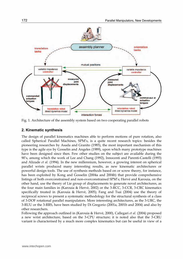
Fig. 1. Architecture of the assembly system based on two cooperating parallel robots
2. Kinematic synthesis
The design of parallel kinematics machines able to perform motions of pure rotation, also called Spherical Parallel Machines, SPM’s, is a quite recent research topics: besides the pioneering researches by Asada and Granito (1985), the most important mechanism of this type is the agile eye by Gosselin and Angeles (1989), upon which many prototype machines have been designed since then. Few other studies on the subject are available during the 90’s, among which the work of Lee and Chang (1992), Innocenti and Parenti-Castelli (1993) and Alizade et al. (1994). In the new millennium, however, a growing interest on spherical parallel wrists produced many interesting results, as new kinematic architectures or powerful design tools. The use of synthesis methods based on or screw theory, for instance, has been exploited by Kong and Gosselin (2004a and 2004b) that provide comprehensive listings of both overconstrained and non-overconstrained SPM’s; Hervé and Karouia, on the other hand, use the theory of Lie group of displacements to generate novel architectures, as the four main families in (Karouia & Hervè, 2002) or the 3-RCC, 3-CCR, 3-CRC kinematics specifically treated in (Karouia & Hervè, 2005); Fang and Tsai (2004) use the theory of reciprocal screws to present a systematic methodology for the structural synthesis of a class of 3-DOF rotational parallel manipulators. More interesting architectures, as the 3-URC, the 3-RUU or the 3-RRS, have been studied by Di Gregorio (2001a, 2001b and 2004) and also by other researchers. Following the approach outlined in (Karouia & Hervè, 2000), Callegari et al. (2004) proposed a new wrist architecture, based on the 3-CPU structure; it is noted also that the 3-CRU variant is characterised by a much more complex kinematics but can be useful in view of a
www.intechopen.com
Design and Prototyping of a Spherical Parallel Machine Based on 3-CPU Kinematics
173
possible prototyping at a mini- or micro- scale, as shown by Callegari et al. (2008). The main synthesis steps of the 3-CPU parallel wrist are outlined in the following paragraphs. First of all, it is noted that only non-overconstrained mechanisms have been searched in order to avoid the strict dimensional and geometric tolerances needed by overconstrained machines during manufacturing and assembly phases. Moreover, the use of passive spherical pairs directly joining the platform to the base has been avoided as well and for economic reasons only modular solutions characterised by three identical legs have been considered. It must be said that these advantages are usually paid with a more complex structure and the possible presence of singular configurations (translation singularities) in which the spherical constraint between platform and base fails.
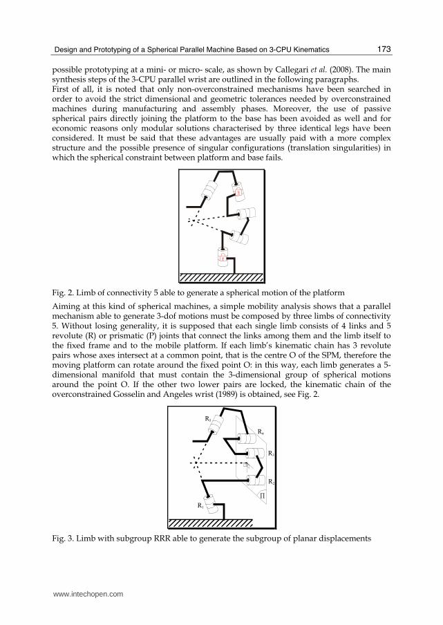
Fig. 2. Limb of connectivity 5 able to generate a spherical motion of the platform
Aiming at this kind of spherical machines, a simple mobility analysis shows that a parallel mechanism able to generate 3-dof motions must be composed by three limbs of connectivity 5. Without losing generality, it is supposed that each single limb consists of 4 links and 5 revolute (R) or prismatic (P) joints that connect the links among them and the limb itself to the fixed frame and to the mobile platform. If each limb’s kinematic chain has 3 revolute pairs whose axes intersect at a common point, that is the centre O of the SPM, therefore the moving platform can rotate around the fixed point O: in this way, each limb generates a 5-dimensional manifold that must contain the 3-dimensional group of spherical motions around the point O. If the other two lower pairs are locked, the kinematic chain of the overconstrained Gosselin and Angeles wrist (1989) is obtained, see Fig. 2.
R1
R2
R3
R4
R5
Π
Fig. 3. Limb with subgroup RRR able to generate the subgroup of planar displacements
www.intechopen.com
Parallel Manipulators, New Developments
174
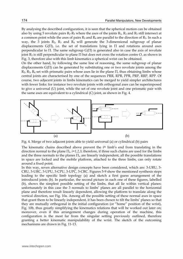
By analysing the described configuration, it is seen that the spherical motion can be obtained also by using 5 revolute pairs R1-R5 where the axes of the joints R1, R3 and R5 still intersect at a common point while the axes of pairs R2 and R4 are parallel to the direction of R3. In such a way, the 3 joints R2, R3 and R4 will generate the 3-dimensional subgroup of planar displacements G(П), i.e. the set of translations lying in П and rotations around axes perpendicular to П. The same subgroup G(П) is generated also in case the axis of revolute joint R3 is still perpendicular to plane П but does not cross the rotation centre O, as shown in Fig. 3, therefore also with this limb kinematics a spherical wrist can be obtained. On the other hand, by following the same line of reasoning, the same subgroup of planar displacements G(П) can be generated by substituting one or two revolute joints among the R2, R3, R4 set with prismatic pairs whose axes lie in the plane П, thus obtaining limbs whose central joints are characterised by one of the sequences PRR, RPR, PPR, PRP, RRP, RPP. Of course, two adjacent joints in limbs kinematics can be merged to yield simpler architectures with fewer links: for instance two revolute joints with orthogonal axes can be superimposed to give a universal (U) joint, while the set of one revolute joint and one prismatic pair with the same axes are equivalent to a cylindrical (C) joint, as shown in Fig. 4.
(a) (b)
Fig. 4. Merge of two adjacent joints able to yield universal (a) or cylindrical (b) pairs
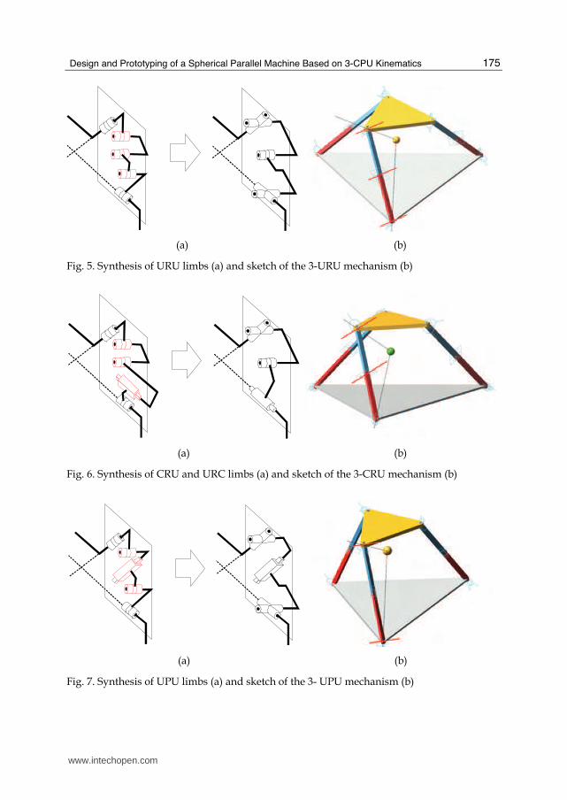
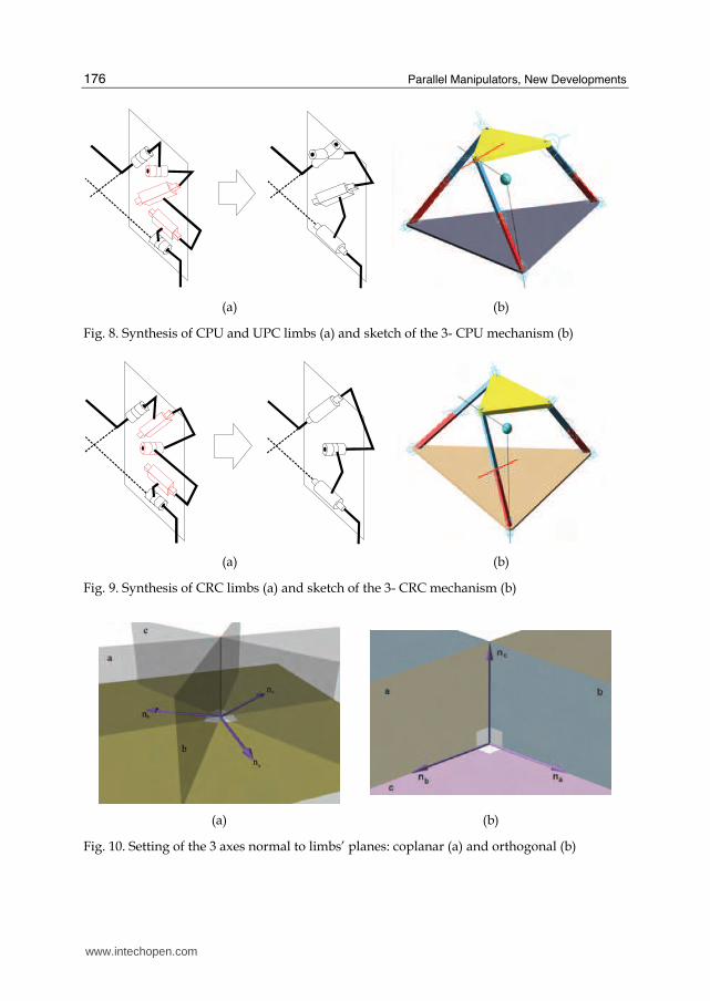
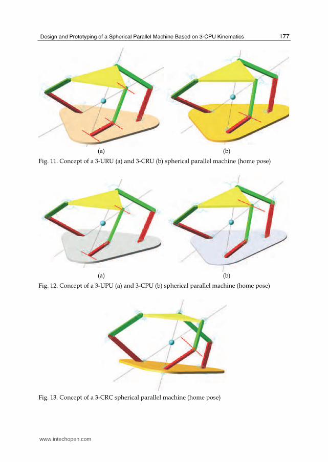
The kinematic chains described above prevent the ith limb’s end from translating in the direction normal to the plane Пi, i=1,2,3; therefore, if three such chains are used for the limbs and the three normals to the planes Пi, are linearly independent, all the possible translations in space are locked and the mobile platform, attached to the three limbs, can only rotate around a fixed point. In this way, seven alternative design concepts have been considered, which are: 3-URU, 3-CRU, 3-URC, 3-UPU, 3-CPU, 3-UPC, 3-CRC. Figures 5-9 show the mentioned synthesis steps leading to the specific limb topology (a) and sketch a first guess arrangement of the introduced joints (b). In particular, the second picture in each one of these figures, labelled (b), shows the simplest possible setting of the limbs, that all lie within vertical planes: unfortunately in this case the 3 normals to limbs’ planes are all parallel to the horizontal plane and therefore result linearly dependent, allowing the platform to translate along the vertical direction, see Fig. 10a. Among all the possible setting of these normal axes in space that grant them to be linearly independent, it has been chosen to tilt the limbs’ planes so that they are mutually orthogonal in the initial configuration (or “home” position of the wrist), Fig. 10b, thus greatly simplifying the kinematics relations that will be worked out later on; moreover, even if this arrangement changes during operation of the machine, this configuration is the most far from the singular setting previously outlined, therefore granting a better kinematic manipulability of the wrist. The sketch of the outcoming mechanisms are drawn in Fig. 11-13.
www.intechopen.com
Design and Prototyping of a Spherical Parallel Machine Based on 3-CPU Kinematics
175
(a) (b)
Fig. 5. Synthesis of URU limbs (a) and sketch of the 3-URU mechanism (b)
(a) (b)
Fig. 6. Synthesis of CRU and URC limbs (a) and sketch of the 3-CRU mechanism (b)
(a) (b)
Fig. 7. Synthesis of UPU limbs (a) and sketch of the 3- UPU mechanism (b)
www.intechopen.com
Parallel Manipulators, New Developments
176
(a) (b)
Fig. 8. Synthesis of CPU and UPC limbs (a) and sketch of the 3- CPU mechanism (b)
(a) (b)
Fig. 9. Synthesis of CRC limbs (a) and sketch of the 3- CRC mechanism (b)
(a) (b)
Fig. 10. Setting of the 3 axes normal to limbs’ planes: coplanar (a) and orthogonal (b)
www.intechopen.com
Design and Prototyping of a Spherical Parallel Machine Based on 3-CPU Kinematics
177
(a) (b)
Fig. 11. Concept of a 3-URU (a) and 3-CRU (b) spherical parallel machine (home pose)
(a) (b)
Fig. 12. Concept of a 3-UPU (a) and 3-CPU (b) spherical parallel machine (home pose)
Fig. 13. Concept of a 3-CRC spherical parallel machine (home pose)
www.intechopen.com
Parallel Manipulators, New Developments
178
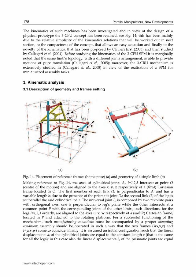
The kinematics of such machines has been investigated and in view of the design of a physical prototype the 3-CPU concept has been retained, see Fig. 14: this has been mainly due to the relative simplicity of the kinematics relations that will be worked out in next section, to the compactness of the concept, that allows an easy actuation and finally to the novelty of the kinematics, that has been proposed by Olivieri first (2003) and then studied by Callegari et al. (2004). Before studying the kinematics of the 3-CPU SPM it is marginally noted that the same limb’s topology, with a different joints arrangement, is able to provide motions of pure translation (Callegari et al., 2005); moreover, the 3-CRU mechanism is extensively studied in (Callegari et. al., 2008) in view of the realisation of a SPM for miniaturized assembly tasks.
3. Kinematic analysis
3.1 Description of geometry and frames setting
(a) (b)
Fig. 14. Placement of reference frames (home pose) (a) and geometry of a single limb (b)
Making reference to Fig. 14, the axes of cylindrical joints Ai, i=1,2,3 intersect at point O (centre of the motion) and are aligned to the axes x, y, z respectively of a (fixed) Cartesian frame located in O. The first member of each link (1) is perpendicular to Ai and has a variable length bi due to the presence of the prismatic joint Di: the second link (2) of the leg is set parallel the said cylindrical pair. The universal joint Bi is composed by two revolute pairs with orthogonal axes: one is perpendicular to leg’s plane while the other intersects at a common point P with the corresponding joints of the other limbs; such directions, for the legs i=1,2,3 orderly, are aligned to the axes u, v, w respectively of a (mobile) Cartesian frame, located in P and attached to the rotating platform. For a successful functioning of the mechanism, such manufacturing conditions must be accompanied by a proper mounting condition: assembly should be operated in such a way that the two frames O(x,y,z) and P(u,v,w) come to coincide. Finally, it is assumed an initial configuration such that the linear displacements ai of the cylindrical joints are equal to the constant length c (that is the same for all the legs): in this case also the linear displacements bi of the prismatic joints are equal
www.intechopen.com
Design and Prototyping of a Spherical Parallel Machine Based on 3-CPU Kinematics
179
to the constant length d. It is also evident that, for practical design considerations, SPM’s based on the 3-CPU concept are efficiently actuated by driving the linear displacements of the cylindrical pairs coupling the limbs with the frame: therefore in the following kinematic analysis it will be made reference to this case (i.e. joint variables ai, i=1,2,3 will be considered the actuation parameters).
3.2 Analysis of mobility
From the discussion of previous section, it is now evident that in case the recalled manufacturing and assembly conditions are satisfied, the mobile platform is characterised by motions of pure rotation; the mentioned conditions can be geometrically expressed by:
i. i1w and
i4w incident in P;
ii. i3w perpendicular to the plane >< ii 41
ˆ,ˆ ww , i.e. 0ˆˆ43 =⋅ ii ww and 0ˆˆ
13 =⋅ ii ww ;
iii. i2w lying on the plane >< ii 41
ˆ,ˆ ww , i.e. 0ˆˆ23 =⋅ ii ww ; due to condition (ii) must
also hold: iii 213
ˆˆˆ www ×= ;
iv. i2w not parallel to
i1w and therefore: 0ww ˆˆˆ21 ≠× ii
(for simplicity, the condition
0ˆˆ21 =⋅ ii ww has been posed).
Making reference to Fig. 14b, if the point P is considered belonging to the ith leg, its velocity can be written in three different ways as follows:
rii PPP $$$ += 2
for i=1,2,3 (1)
where i2P
$ is the velocity of point P if considered fixed to link 2:
iiiiiii dBP 4222
ˆ )( wωBωBP ×+=−×+= $$$ (2)
and riP
$ is the velocity of point P relative to a frame fixed to link 2 and with origin in Bi:
( ) iiiiiiri dBP 43333ˆˆˆ wwwP ×=−×= θθ $$$ (3)
In (2), ω2i is the angular velocity of link 2:
iii 112 wω θ$= (4)
In the same way, with obvious meaning of the symbols, the vector iB
$ can be expressed as:
riii BBB $$$ += 1
for i=1,2,3 (5)
where:
iiiiiiiiiiiiiiiiii dadaaABa 411141111111
ˆˆˆ)ˆˆ(ˆˆ)(ˆ wwwwwwwωwB ×−=−×+=−×+= θθ $$$$$$ (6)
iiri b 2wB $$ = (7)
If (2)-(7) are substituted back in (1), it is found:
iiiiiii dab 43312
ˆˆˆˆ wwwwP ×++= θ$$$$ for i=1,2,3 (8)
www.intechopen.com
Parallel Manipulators, New Developments
180
By dot-multiplying (8) by i3w and by taking into account the conditions (i)-(iv), it is finally
obtained:
0ˆ3 =⋅Pw $i
(9)
that can be differentiated to yield:
0ˆˆ33 =⋅+⋅ PwPw $$$$ii
(10)
Equations (9-10), written for the 3 legs, build up a system of 6 linear algebraic equations in 6
unknowns, the scalar components of P$ and P$$ . Such a system can be written in matrix form
as follows:
0P
PM =⎥⎦
⎤⎢⎣⎡$$$
(11)
where the 6x6 matrix M can be partitioned as:
⎥⎦⎤⎢⎣
⎡=HH
OHM $
(12)
with:
⎥⎥⎥⎦
⎤⎢⎢⎢⎣
⎡=
⎥⎥⎥⎦
⎤⎢⎢⎢⎣
⎡=
kji
kji
kji
T
T
T
www
www
www
333333
323232
313131
33
32
31
ˆ
ˆ
ˆ
w
w
w
H (13)
and O being the 3x3 null matrix.
If the matrix M is not singular, the system (11) only admits the trivial null solution:
0PP == $$$ (14-15)
which means that the point P does not move in space, i.e. the moving platform only rotates
around P. The singular configurations, on the other hand, can be identified by posing:
( ) ( )[ ] 0detdet2 == HM (16)
that leads to:
( ) 0ˆˆˆdet 333231 =×⋅= wwwH (17)
Equation (17) is satisfied only when the three unit vectors 31w ,
32w , 33w are linearly
dependent; therefore the platform incurs in a translation singularity if and only if:
• the planes containing the three legs are simultaneously perpendicular to the base plane;
• such planes are coincident with the base plane (configuration not reachable);
• at least two out of the three aforementioned planes admit parallel normal unit vectors.
www.intechopen.com
Design and Prototyping of a Spherical Parallel Machine Based on 3-CPU Kinematics
181
This justifies the choice previously operated of having the legs laid on mutual orthogonal
planes: in fact this configuration is the most far from singularities.
3.3 Orientation kinematics
Orientation kinematics is based on the definition of the relative rotation between fixed frame O(x,y,z) and the mobile frame P(u,v,w), where is always P≡O, see Fig. 14; to this aim the following set of Cardan angles is used:
( ) ( ) ( ) ( )⎥⎥⎥⎦
⎤⎢⎢⎢⎣
⎡++−
−+−+−
=⋅⋅=βαγαγβαγαγβαβαγαγβαγαγβα
βγβγβγβαγβα
cccssscsscsc
csccssssccss
ssccc
zyx
O
P RRRR ,, (18)
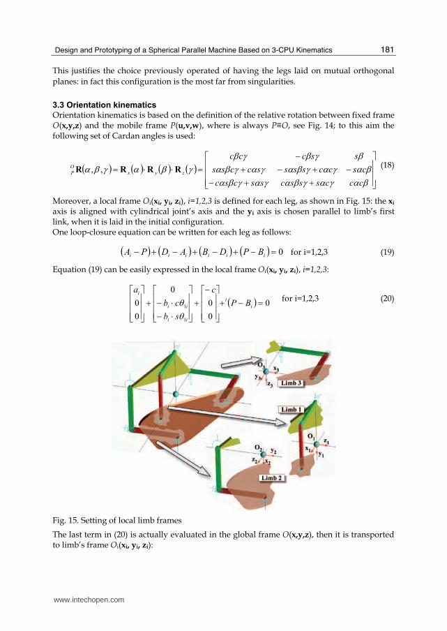
Moreover, a local frame Oi(xi, yi, zi), i=1,2,3 is defined for each leg, as shown in Fig. 15: the xi axis is aligned with cylindrical joint’s axis and the yi axis is chosen parallel to limb’s first link, when it is laid in the initial configuration. One loop-closure equation can be written for each leg as follows:
( ) ( ) ( ) ( ) 0=−+−+−+− iiiiii BPDBADPA for i=1,2,3 (19)
Equation (19) can be easily expressed in the local frame Oi(xi, yi, zi), i=1,2,3:
( ) 0
0
0
0
0
0
1
1 =−+⎥⎥⎥⎦
⎤⎢⎢⎢⎣
⎡−+
⎥⎥⎥⎦
⎤⎢⎢⎢⎣
⎡⋅−⋅−+
⎥⎥⎥⎦
⎤⎢⎢⎢⎣
⎡i
i
ii
ii
i
BP
c
sb
cb
a
θθ for i=1,2,3 (20)
Fig. 15. Setting of local limb frames
The last term in (20) is actually evaluated in the global frame O(x,y,z), then it is transported to limb’s frame Oi(xi, yi, zi):
www.intechopen.com
Parallel Manipulators, New Developments
182
( ) ( ) ( )iPO
P
i
Oi
Pi
Pi
iBPBPBP −⋅⋅=−⋅=− RRR for i=1,2,3 (21)
where the introduced terms assume the following values:
⎥⎥⎥⎦
⎤⎢⎢⎢⎣
⎡=
100
010
0011RO
⎥⎥⎥⎦
⎤⎢⎢⎢⎣
⎡=
001
100
0102RO
⎥⎥⎥⎦
⎤⎢⎢⎢⎣
⎡=
010
001
1001RO
(22-24)
( ) [ ]TPdBP 0101 ⋅=− ( ) [ ]TP
dBP 1002 ⋅=− ( ) [ ]TPdBP 0013 ⋅=− (25-27)
In inverse kinematics the values of α, β, γ Cardan angles (or equivalently the elements rij of
the rotation matrix RO
P) are know and the joint variables ai must be found; loop closure
equations (21) for i=1,2,3 represent three decoupled systems of non linear algebraic
equations in the unknowns ai, θ1i and bi, that can be solved to find the single solution:
( )⎪⎪⎪⎩
⎪⎪⎪⎨
⎧
⋅==
⋅−=
11
221
223211
121
,2atan
θ
θ
c
rdb
rr
rdca
( )⎪⎪⎪⎩
⎪⎪⎪⎨
⎧
⋅==
⋅−=
12
332
331312
232
,2atan
θ
θ
c
rdb
rr
rdca
( )⎪⎪⎪⎩
⎪⎪⎪⎨
⎧
⋅==
⋅−=
13
113
112113
313
,2atan
θ
θ
c
rdb
rr
rdca
(28-30)
The direct kinematic problem, on the other hand, assumes the knowledge of joint variables
ai, i=1,2,3 and aims at finding the corresponding attitudes of the platform in the space. The
analysis is performed by means of simple trigonometric manipulations: by substituting in
(28-30) the expression of rij given in (18), it is obtained:
⎪⎪⎪⎩
⎪⎪⎪⎨⎧
=−=−=−=
=−=
33
22
11
kd
acsscsc
kd
accs
kd
acsc
γαγβαβαγβ
(31)
where the ki, i=1,2,3 are known values. The 3 equations in (31) can be solved to find up to 4
admissible values for sγ: ( )2
2 4 2 2 2 2 23 2 22 3 2 1 12
1 1
2 1 1 0k k k
k s k k k s kk k
γ γ⎛ ⎞− + + + − − − + =⎜ ⎟⎝ ⎠ (32)
For each angle γ that solves (32), 2 different values can be found for angles β and α:
γβs
kc 1= γα s
k
ks
1
2= (33-34)
www.intechopen.com
Design and Prototyping of a Spherical Parallel Machine Based on 3-CPU Kinematics
183
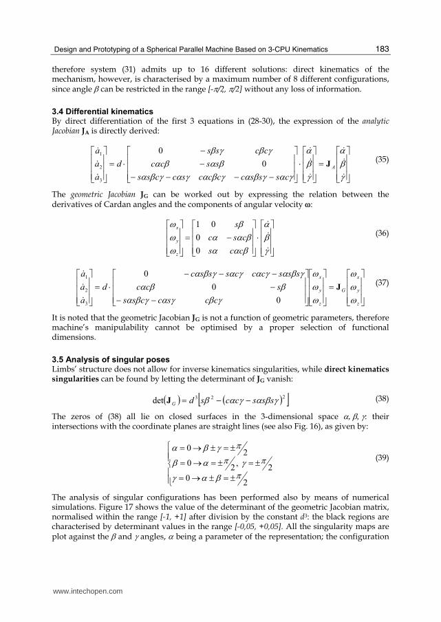
therefore system (31) admits up to 16 different solutions: direct kinematics of the mechanism, however, is characterised by a maximum number of 8 different configurations, since angle β can be restricted in the range [-π/2, π/2] without any loss of information.
3.4 Differential kinematics By direct differentiation of the first 3 equations in (28-30), the expression of the analytic Jacobian JA is directly derived:
⎥⎥⎥⎦
⎤⎢⎢⎢⎣
⎡=
⎥⎥⎥⎦
⎤⎢⎢⎢⎣
⎡⋅
⎥⎥⎥⎦
⎤⎢⎢⎢⎣
⎡−−−−
−−
⋅=⎥⎥⎥⎦
⎤⎢⎢⎢⎣
⎡γβα
γβα
γαγβαγβαγαγβαβαβα
γβγβ$
$$
$
$$
$$$
A
csssccccsccss
sscc
ccss
d
a
a
a
J0
0
3
2
1
(35)
The geometric Jacobian JG can be worked out by expressing the relation between the derivatives of Cardan angles and the components of angular velocity ω:
⎥⎥⎥⎦
⎤⎢⎢⎢⎣
⎡⋅
⎥⎥⎥⎦
⎤⎢⎢⎢⎣
⎡−=
⎥⎥⎥⎦
⎤⎢⎢⎢⎣
⎡γβα
βααβαα
βωωω
$
$$
ccs
csc
s
z
y
x
0
0
01 (36)
⎥⎥⎥⎦
⎤⎢⎢⎢⎣
⎡=
⎥⎥⎥⎦
⎤⎢⎢⎢⎣
⎡⎥⎥⎥⎦
⎤⎢⎢⎢⎣
⎡−−
−−−−
⋅=⎥⎥⎥⎦
⎤⎢⎢⎢⎣
⎡
z
y
x
G
z
y
x
ccsccss
scc
ssscccsssc
d
a
a
a
ωωω
ωωω
γβγαγβαββα
γβαγαγαγβαJ
0
0
0
3
2
1
$$$
(37)
It is noted that the geometric Jacobian JG is not a function of geometric parameters, therefore machine’s manipulability cannot be optimised by a proper selection of functional dimensions.
3.5 Analysis of singular poses Limbs’ structure does not allow for inverse kinematics singularities, while direct kinematics singularities can be found by letting the determinant of JG vanish:
( ) ( )[ ]223det γβαγαβ sssccsdG −−=J (38)
The zeros of (38) all lie on closed surfaces in the 3-dimensional space α, β, γ: their intersections with the coordinate planes are straight lines (see also Fig. 16), as given by:
⎪⎪⎩⎪⎪⎨⎧
±=±→=±=±=→=
±=±→=
20
2 ,
20
20
πβαγπγπαβ
πγβα (39)
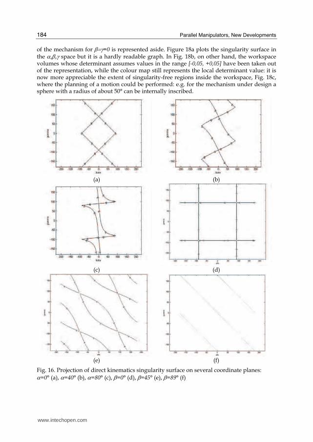
The analysis of singular configurations has been performed also by means of numerical simulations. Figure 17 shows the value of the determinant of the geometric Jacobian matrix, normalised within the range [-1, +1] after division by the constant d3: the black regions are characterised by determinant values in the range [-0,05, +0,05]. All the singularity maps are plot against the β and γ angles, α being a parameter of the representation; the configuration
www.intechopen.com
Parallel Manipulators, New Developments
184
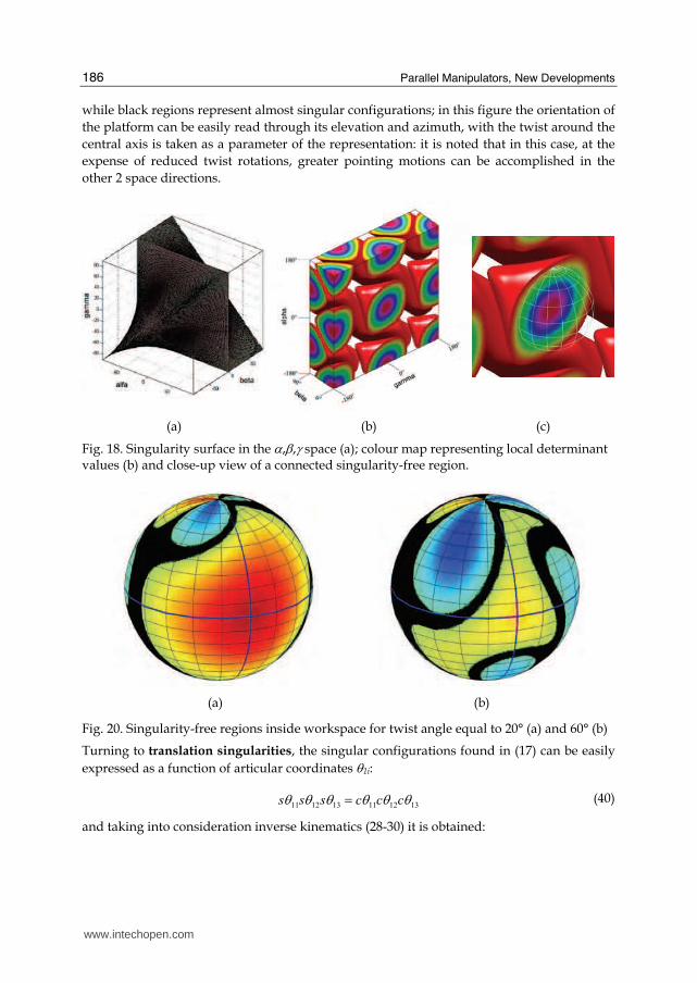
of the mechanism for β=γ=0 is represented aside. Figure 18a plots the singularity surface in the α,β,γ space but it is a hardly readable graph. In Fig. 18b, on other hand, the workspace volumes whose determinant assumes values in the range [-0,05, +0,05] have been taken out of the representation, while the colour map still represents the local determinant value: it is now more appreciable the extent of singularity-free regions inside the workspace, Fig. 18c, where the planning of a motion could be performed: e.g. for the mechanism under design a sphere with a radius of about 50° can be internally inscribed.
(a) (b)
(c) (d)
(e) (f)
Fig. 16. Projection of direct kinematics singularity surface on several coordinate planes: α=0° (a), α=40° (b), α=80° (c), β=0° (d), β=45° (e), β=89° (f)
www.intechopen.com
Design and Prototyping of a Spherical Parallel Machine Based on 3-CPU Kinematics
185
(a)
(b)
(c)
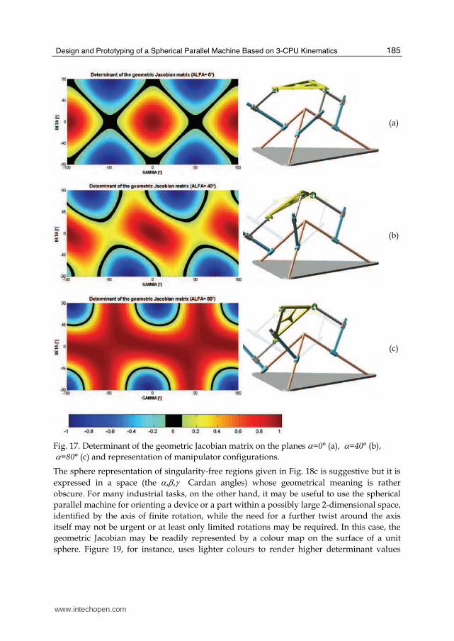
Fig. 17. Determinant of the geometric Jacobian matrix on the planes α=0° (a), α=40° (b), α=80° (c) and representation of manipulator configurations.
The sphere representation of singularity-free regions given in Fig. 18c is suggestive but it is
expressed in a space (the α,β,γ Cardan angles) whose geometrical meaning is rather
obscure. For many industrial tasks, on the other hand, it may be useful to use the spherical
parallel machine for orienting a device or a part within a possibly large 2-dimensional space,
identified by the axis of finite rotation, while the need for a further twist around the axis
itself may not be urgent or at least only limited rotations may be required. In this case, the
geometric Jacobian may be readily represented by a colour map on the surface of a unit
sphere. Figure 19, for instance, uses lighter colours to render higher determinant values
www.intechopen.com
Parallel Manipulators, New Developments
186
while black regions represent almost singular configurations; in this figure the orientation of
the platform can be easily read through its elevation and azimuth, with the twist around the
central axis is taken as a parameter of the representation: it is noted that in this case, at the
expense of reduced twist rotations, greater pointing motions can be accomplished in the
other 2 space directions.
(a) (b) (c)
Fig. 18. Singularity surface in the α,β,γ space (a); colour map representing local determinant values (b) and close-up view of a connected singularity-free region.
(a) (b)
Fig. 20. Singularity-free regions inside workspace for twist angle equal to 20° (a) and 60° (b)
Turning to translation singularities, the singular configurations found in (17) can be easily
expressed as a function of articular coordinates θ1i:
131211131211 θθθθθθ cccsss = (40)
and taking into consideration inverse kinematics (28-30) it is obtained:
www.intechopen.com
Design and Prototyping of a Spherical Parallel Machine Based on 3-CPU Kinematics
187
113322211332 rrrrrr = (41)
Equation (41) is a useful expression of translation singularities in task space, where the elements of the rotation matrix are used; by using the definition of the rotation matrix in (18) and after some trigonometric manipulation, an alternative expression can be obtained in
function of Cardan angles α, β, γ :
0)( 22 =−− γβαγαβ sssccs (42)
It is noted that (42) vanishes in the same configurations of (38), therefore translation singularities coincide with direct kinematics singularities, i.e. no additional singular surfaces are present inside workspace.
3.5 Analysis of static loads
The static analysis is useful in the first phases of machine design for the selection of machine’s motors and for a first design of the links, with the related connecting bearings. The base relation is provided as usual by the well known duality between kinematics and
statics, which allows a straightforward assessment of the actuation efforts τ needed to balance a moment npl applied at the mobile platform:
⎥⎥⎥⎦
⎤⎢⎢⎢⎣
⎡=
⎥⎥⎥⎦
⎤⎢⎢⎢⎣
⎡−
plz
ply
plx
T
G
n
n
n
J
3
2
1
τττ
(43)
It must be noted that the application of a force fpl at the centre of the spherical motion does not require balancing forces by the actuators but it is entirely born by frame bearings: the internal reactions at the bearings caused by the application of the mentioned external wrench have been evaluated as well and used during structural design.
4. Dynamics
4.1 Inverse dynamics model
In this section an inverse dynamics model of the 3-CPU mechanism is worked out by using
the virtual work principle: it is assumed that frictional forces at the joints are negligible,
therefore the work produced by the constraint forces at the joints is zero and only active
forces (including the gravitational effects) must be accounted in the developments.
In the derivation of the model, the notation is based on Fig. 14b and the second subscript i
(i=1,2,3) indicates the ith limb while the first subscript j (j=1,2) refers to the first or second
link respectively. Namely, mji and Iji are the mass and (central) inertia tensor of the jth
member of the ith limb; ωji is its angular velocity and vji is the linear velocity of its centre of
mass; mpl, Ipl, ωpl, vpl are the same quantities referred to the mobile platform.
The total wrench of active and inertial effects acting on the centre of mass of jth member of
the ith limb is written as:
⎥⎦⎤⎢⎣
⎡×−−
−=⎥⎦⎤⎢⎣
⎡=)( jijijijiji
jijiji
ji
ji
ji ωIωωIvg
n
fF $
$$
mm (44)
www.intechopen.com
Parallel Manipulators, New Developments
188
In the same manner, the total wrench acting on the centre of mass of the mobile platform is:
⎥⎦⎤⎢⎣
⎡+×−−
+−=⎥⎦⎤⎢⎣
⎡=eplplplplpl
eplpl
pl
pl
pl )(
)(
nωIωωIfvg
n
fF $
$$
m (45)
where fe and ne are the external force and moment applied to its centre of mass; it is
accidentally noted that the centre of mass of the platform does not coincide with the fixed
point O. If τ is the vector of the actuation forces and q are the corresponding displacements,
the principle of virtual work can be written for the present case:
( ) ( ) ( )( ) 03
1
2
1
jijiplpl =⎟⎟⎠⎞⎜⎜⎝
⎛+⋅+⋅ ∑ ∑= =i j
TTT δδδ FxFxτq (46)
where the vector xji gathers the position of the centre of mass of jth member of the ith limb
and the orientation of the same link and xpl expresses the position of the centre of mass of
the mobile platform and its orientation. It is noted that all the infinitesimal rotations
appearing in (46) must be expressed as functions of the angular velocity of the respective
link, e.g. for the platform:
[ ] tωωωvvvT
plzplyplxplzplyplx δδ ⋅=plx (47)
Since all the virtual displacements in (47) must be compatible with the constraints, they are
not independent but can rather be expressed as functions of an independent set of
Lagrangian coordinates; if the Cardan angles φ=[α, β, γ]T of the mobile platform are chosen
for this purpose, the following relations hold between the introduced virtual displacements:
φJq δδ ⋅= φJx δδ jiji ⋅= φJx δδ plpl ⋅= (48-50)
where J, Jji and Jpl are proper Jacobian matrices that can be found through the usual velocity
analysis of the mechanism. Equation (46) can be written again as:
03
1
2
1
jijiplpl =⎥⎥⎦⎤
⎢⎢⎣⎡
⎟⎟⎠⎞⎜⎜⎝
⎛ ⋅+⋅+⋅⋅ ∑ ∑= =i j
TTTTFJFJτJφδ (51)
Since (51) is valid for any virtual displacement δφ of the platform, in non-singular
configurations it is:
⎟⎟⎠⎞
⎜⎜⎝⎛
⎟⎟⎠⎞⎜⎜⎝
⎛ ⋅+⋅⋅−= ∑ ∑= =− 3
1
2
1
jijiplpl
i j
TTTFJFJJτ (52)
Equation (52) completely describes manipulator’s dynamics; all the elements in it have been
worked out and the resulting model has been proofed by comparison with commercial
packages’ output, see (Callegari & Marzetti, 2006).
www.intechopen.com
Design and Prototyping of a Spherical Parallel Machine Based on 3-CPU Kinematics
189
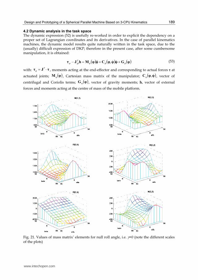
4.2 Dynamic analysis in the task space The dynamic expression (52) is usefully re-worked in order to explicit the dependency on a proper set of Lagrangian coordinates and its derivatives. In the case of parallel kinematics machines, the dynamic model results quite naturally written in the task space, due to the (usually) difficult expression of DKP; therefore in the present case, after some cumbersome manipulation, it is obtained:
( ) ( ) ( )φGφφφCφφMhJτ φφφϕ ++=− $$$$ ,pl
T (53)
with: τJτ ⋅= Tϕ , moments acting at the end-effector and corresponding to actual forces τ at
actuated joints; ( )φMφ , Cartesian mass matrix of the manipulator; ( )φφC $,φ , vector of
centrifugal and Coriolis terms; ( )φG φ , vector of gravity moments; h, vector of external
forces and moments acting at the centre of mass of the mobile platform.
Fig. 21. Values of mass matrix’ elements for null roll angle, i.e. γ=0 (note the different scales of the plots)
www.intechopen.com
Parallel Manipulators, New Developments
190
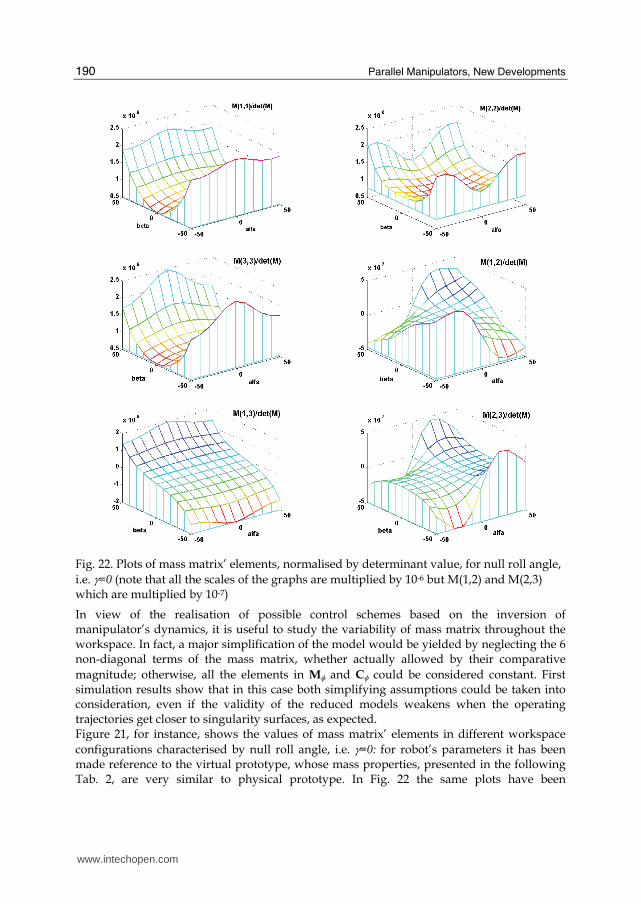
Fig. 22. Plots of mass matrix’ elements, normalised by determinant value, for null roll angle,
i.e. γ=0 (note that all the scales of the graphs are multiplied by 10-6 but M(1,2) and M(2,3) which are multiplied by 10-7)
In view of the realisation of possible control schemes based on the inversion of manipulator’s dynamics, it is useful to study the variability of mass matrix throughout the workspace. In fact, a major simplification of the model would be yielded by neglecting the 6 non-diagonal terms of the mass matrix, whether actually allowed by their comparative
magnitude; otherwise, all the elements in Mφ and Cφ could be considered constant. First simulation results show that in this case both simplifying assumptions could be taken into consideration, even if the validity of the reduced models weakens when the operating trajectories get closer to singularity surfaces, as expected. Figure 21, for instance, shows the values of mass matrix’ elements in different workspace
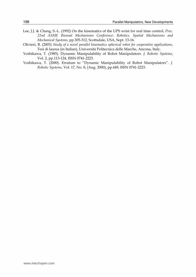
configurations characterised by null roll angle, i.e. γ=0: for robot’s parameters it has been made reference to the virtual prototype, whose mass properties, presented in the following Tab. 2, are very similar to physical prototype. In Fig. 22 the same plots have been
www.intechopen.com
Design and Prototyping of a Spherical Parallel Machine Based on 3-CPU Kinematics
191
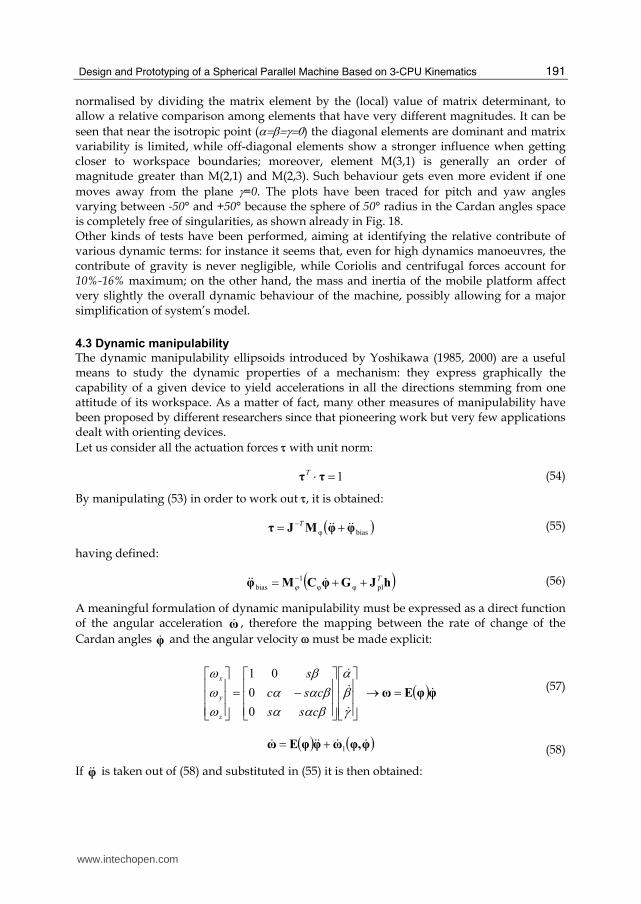
normalised by dividing the matrix element by the (local) value of matrix determinant, to allow a relative comparison among elements that have very different magnitudes. It can be
seen that near the isotropic point (α=β=γ=0) the diagonal elements are dominant and matrix variability is limited, while off-diagonal elements show a stronger influence when getting closer to workspace boundaries; moreover, element M(3,1) is generally an order of magnitude greater than M(2,1) and M(2,3). Such behaviour gets even more evident if one
moves away from the plane γ=0. The plots have been traced for pitch and yaw angles varying between -50° and +50° because the sphere of 50° radius in the Cardan angles space is completely free of singularities, as shown already in Fig. 18. Other kinds of tests have been performed, aiming at identifying the relative contribute of various dynamic terms: for instance it seems that, even for high dynamics manoeuvres, the contribute of gravity is never negligible, while Coriolis and centrifugal forces account for 10%-16% maximum; on the other hand, the mass and inertia of the mobile platform affect very slightly the overall dynamic behaviour of the machine, possibly allowing for a major simplification of system’s model.
4.3 Dynamic manipulability
The dynamic manipulability ellipsoids introduced by Yoshikawa (1985, 2000) are a useful means to study the dynamic properties of a mechanism: they express graphically the capability of a given device to yield accelerations in all the directions stemming from one attitude of its workspace. As a matter of fact, many other measures of manipulability have been proposed by different researchers since that pioneering work but very few applications dealt with orienting devices.
Let us consider all the actuation forces τ with unit norm:
1=⋅ ττT (54)
By manipulating (53) in order to work out τ, it is obtained:
( )biasφ φφMJτ $$$$ += −T (55)
having defined:
( )hJGφCMφ T
plφφ1
bias ++= − $$$ ϕ (56)
A meaningful formulation of dynamic manipulability must be expressed as a direct function of the angular acceleration ω$ , therefore the mapping between the rate of change of the
Cardan angles φ$ and the angular velocity ω must be made explicit:
( )φφEω $$
$$
=→⎥⎥⎥⎦
⎤⎢⎢⎢⎣
⎡⎥⎥⎥⎦
⎤⎢⎢⎢⎣
⎡−=
⎥⎥⎥⎦
⎤⎢⎢⎢⎣
⎡γβα
βααβαα
βωωω
css
csc
s
z
y
x
0
0
01 (57)
( ) ( )φφ,ωφφEω $$$$$1+= (58)
If φ$$ is taken out of (58) and substituted in (55) it is then obtained:
www.intechopen.com
Parallel Manipulators, New Developments
192
( )bias
1
φ ωωEMJτ $$ += −−T (59)
having defined:
( )hJGφCMJEMωω TT
plφφ11
1bias +++−= −− $$$ ϕϕ (60)
The constraint expressed by (54) can be finally written in the following quadratic form:
( ) 1=⋅⋅ ΩφΓΩ $$ T (61)
with obvious meaning of the introduced terms:
( )hJGφCMJEMωωωωΩ TT
plφφ11
1bias +++−=+= −− $$$$$$ ϕϕ (62)
( ) 1
φ1 −−−−= EMJJMEφΓ TTT ϕ (63)
The inspection of (62-64) shows that gravity merely induces a translation of the dynamic manipulability ellipsoid while in general velocity has a complex, non-negligible effect on manipulability. Making reference to the remarkable case of a fixed platform ( 0φ =$ ) with no
external or gravity action applied (h=Gφ=0), (61) provides:
( ) 1=⋅⋅ ωφΓω $$ T (64)
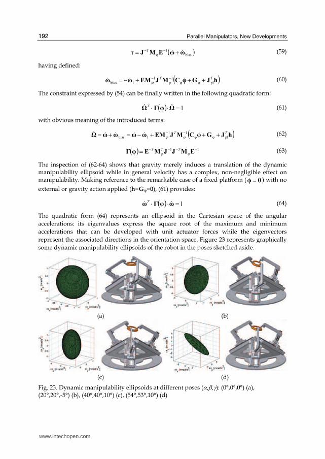
The quadratic form (64) represents an ellipsoid in the Cartesian space of the angular
accelerations: its eigenvalues express the square root of the maximum and minimum
accelerations that can be developed with unit actuator forces while the eigenvectors
represent the associated directions in the orientation space. Figure 23 represents graphically
some dynamic manipulability ellipsoids of the robot in the poses sketched aside.
(a) (b)
(c) (d)
Fig. 23. Dynamic manipulability ellipsoids at different poses (α,β,γ): (0°,0°,0°) (a), (20°,20°,-5°) (b), (40°,40°,10°) (c), (54°,53°,10°) (d)
www.intechopen.com
Design and Prototyping of a Spherical Parallel Machine Based on 3-CPU Kinematics
193
5. Prototype design
The design of a first prototype has been developed, aiming at obtaining high dynamics performances; as reference figures, the following requirements have been posed:
• orientation range (elevation and azimuth): 150°
• maximum angular velocity: 500 °/s
• maximum angular acceleration: 5 000 °/s2
• spatial resolution: 0.01 °
• overall dimensions of the machine: maximum volume of 1 m3. The particular form of the Jacobian matrix (35) does not allow for a mechanical design based
on the optimisation of kinematic properties, since JG is not function of robot’s geometry,
therefore heuristic considerations have been made in a first phase, in order to limit wrist’s
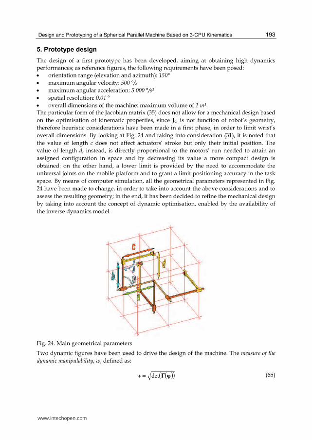
overall dimensions. By looking at Fig. 24 and taking into consideration (31), it is noted that
the value of length c does not affect actuators’ stroke but only their initial position. The
value of length d, instead, is directly proportional to the motors’ run needed to attain an
assigned configuration in space and by decreasing its value a more compact design is
obtained: on the other hand, a lower limit is provided by the need to accommodate the
universal joints on the mobile platform and to grant a limit positioning accuracy in the task
space. By means of computer simulation, all the geometrical parameters represented in Fig.
24 have been made to change, in order to take into account the above considerations and to
assess the resulting geometry; in the end, it has been decided to refine the mechanical design
by taking into account the concept of dynamic optimisation, enabled by the availability of
the inverse dynamics model.
Fig. 24. Main geometrical parameters
Two dynamic figures have been used to drive the design of the machine. The measure of the
dynamic manipulability, w, defined as:
( )( )φΓdet=w (65)
www.intechopen.com
Parallel Manipulators, New Developments
194
results proportional to the volume of the manipulation ellipsoid and therefore yields an
overall information on the global manipulation capabilities, but fails to capture the closeness
to singular configurations or even the anisotropy of local dynamics. On the other hand, the
index of dynamic manipulability, i, can be defined as:
max
min λλ=i (66)
with λmin, λmax minimum and maximum eigenvalues of the matrix ( )φΓ : the index (66) is
independent from the volume of the ellipsoid and vanishes close to singular configurations.
(a) (b) (c)
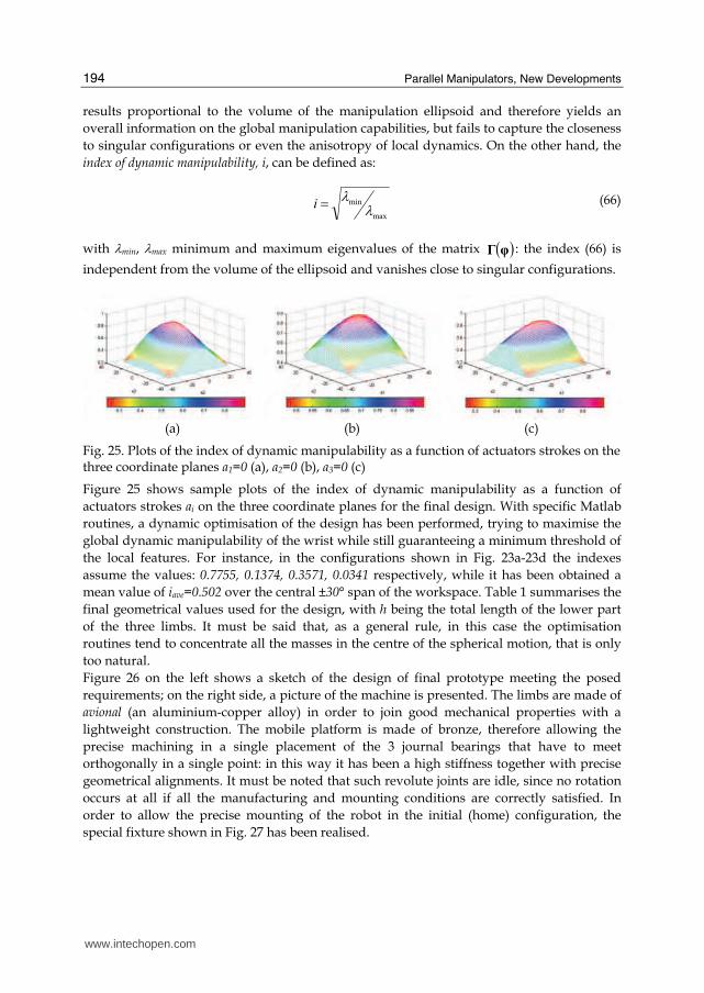
Fig. 25. Plots of the index of dynamic manipulability as a function of actuators strokes on the three coordinate planes a1=0 (a), a2=0 (b), a3=0 (c)
Figure 25 shows sample plots of the index of dynamic manipulability as a function of
actuators strokes ai on the three coordinate planes for the final design. With specific Matlab
routines, a dynamic optimisation of the design has been performed, trying to maximise the
global dynamic manipulability of the wrist while still guaranteeing a minimum threshold of
the local features. For instance, in the configurations shown in Fig. 23a-23d the indexes
assume the values: 0.7755, 0.1374, 0.3571, 0.0341 respectively, while it has been obtained a
mean value of iave=0.502 over the central ±30° span of the workspace. Table 1 summarises the
final geometrical values used for the design, with h being the total length of the lower part
of the three limbs. It must be said that, as a general rule, in this case the optimisation
routines tend to concentrate all the masses in the centre of the spherical motion, that is only
too natural.
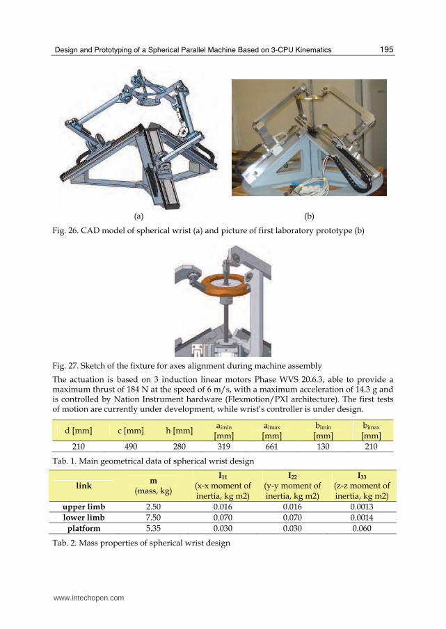
Figure 26 on the left shows a sketch of the design of final prototype meeting the posed
requirements; on the right side, a picture of the machine is presented. The limbs are made of
avional (an aluminium-copper alloy) in order to join good mechanical properties with a
lightweight construction. The mobile platform is made of bronze, therefore allowing the
precise machining in a single placement of the 3 journal bearings that have to meet
orthogonally in a single point: in this way it has been a high stiffness together with precise
geometrical alignments. It must be noted that such revolute joints are idle, since no rotation
occurs at all if all the manufacturing and mounting conditions are correctly satisfied. In
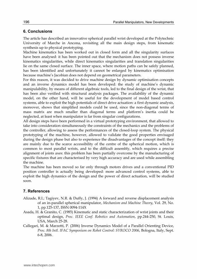
order to allow the precise mounting of the robot in the initial (home) configuration, the
special fixture shown in Fig. 27 has been realised.
www.intechopen.com
Design and Prototyping of a Spherical Parallel Machine Based on 3-CPU Kinematics
195
(a) (b)
Fig. 26. CAD model of spherical wrist (a) and picture of first laboratory prototype (b)
Fig. 27. Sketch of the fixture for axes alignment during machine assembly
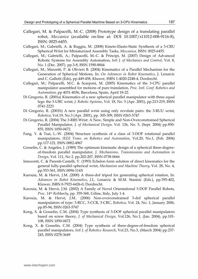
The actuation is based on 3 induction linear motors Phase WVS 20.6.3, able to provide a maximum thrust of 184 N at the speed of 6 m/s, with a maximum acceleration of 14.3 g and is controlled by Nation Instrument hardware (Flexmotion/PXI architecture). The first tests of motion are currently under development, while wrist’s controller is under design.
d [mm] c [mm] h [mm] aimin
[mm] aimax [mm]
bimin
[mm] bimax [mm]
210 490 280 319 661 130 210
Tab. 1. Main geometrical data of spherical wrist design
link m
(mass, kg)
I11 (x-x moment of inertia, kg m2)
I22 (y-y moment of inertia, kg m2)
I33 (z-z moment of inertia, kg m2)
upper limb 2.50 0.016 0.016 0.0013
lower limb 7.50 0.070 0.070 0.0014
platform 5.35 0.030 0.030 0.060
Tab. 2. Mass properties of spherical wrist design
www.intechopen.com
Parallel Manipulators, New Developments
196
6. Conclusions
The article has described an innovative spherical parallel wrist developed at the Polytechnic University of Marche in Ancona, revisiting all the main design steps, from kinematic synthesis up to physical prototyping. Machine kinematics has been worked out in closed form and all the singularity surfaces have been analysed: it has been pointed out that the mechanism does not possess inverse kinematics singularities, while direct kinematics singularities and translation singularities lie on the same closed surface. The inner space, where motion paths can be safely planned, has been identified and unfortunately it cannot be enlarged by kinematics optimisation because machine’s Jacobian does not depend on geometrical parameters. For this reason, it was decided to drive machine design by dynamic optimisation concepts and an inverse dynamics model has been developed: the study of machine’s dynamic manipulability, by means of different algebraic tools, led to the final design of the wrist, that has been also verified with structural analysis packages. The availability of the dynamic model, on the other hand, will be useful for the development of model based control systems, able to exploit the high potentials of direct drive actuation: a first dynamic analysis, moreover, shows that simplified models could be used, since the non-diagonal terms of mass matrix are much smaller than diagonal terms and platform’s inertia could be neglected, at least when manipulator is far from singular configurations. All design steps have been performed in a virtual prototyping environment, that allowed to take into consideration simultaneously the constraints of the mechanics and the problems of the controller, allowing to assess the performances of the closed-loop system. The physical prototyping of the machine, however, allowed to validate the good properties envisaged during the design phase but also to experience the disadvantages of the concept itself: they are mainly due to the scarce accessibility of the centre of the spherical motion, which is common to most parallel wrists, and to the difficult assembly, which requires a precise alignment of joints axes: this problem has been partially overcome by the manufacturing of specific fixtures that are characterised by very high accuracy and are used while assembling the machine. The machine has been moved so far only through motors drives and a conventional PID position controller is actually being developed: more advanced control systems, able to exploit the high dynamics of the design and the power of direct actuation, will be studied soon.
7. References
Alizade, R.I.; Tagiyev, N.R. & Duffy, J. (1994) A forward and reverse displacement analysis of an in-parallel spherical manipulator, Mechanism and Machine Theory, Vol. 29, No. 1, pp.125-137, ISSN 0094-114X
Asada, H. & Granito, C. (1985) Kinematic and static characterization of wrist joints and their optimal design, Proc. IEEE Conf. Robotics and Automation, pp.244-250, St. Louis, USA, March 25-28.
Callegari, M. & Marzetti, P. (2006) Inverse Dynamics Model of a Parallel Orienting Device, Proc. 8th Intl. IFAC Symposium on Robot Control: SYROCO 2006, Bologna, Italy, Sept. 6-8, 2006.
www.intechopen.com
Design and Prototyping of a Spherical Parallel Machine Based on 3-CPU Kinematics
197
Callegari, M. & Palpacelli, M.-C. (2008) Prototype design of a translating parallel robot, Meccanica (available on-line at: DOI 10.1007/s11012-008-9116-8), ISSN: 0025-6455.
Callegari, M.; Gabrielli, A. & Ruggiu, M. (2008) Kineto-Elasto-Static Synthesis of a 3-CRU Spherical Wrist for Miniaturized Assembly Tasks, Meccanica, ISSN: 0025-6455.
Callegari, M.; Gabrielli, A.; Palpacelli, M.-C. & Principi, M. (2007) Design of Advanced Robotic Systems for Assembly Automation, Intl J. of Mechanics and Control, Vol. 8, No. 1 (Dec. 2007). pp.3-8, ISSN 1590-8844
Callegari, M.; Marzetti, P. & Olivieri B. (2004) Kinematics of a Parallel Mechanism for the Generation of Spherical Motions, In: On Advances in Robot Kinematics, J. Lenarcic and C. Galletti (Eds), pp.449-458, Kluwer, ISBN 1-4020-2248-4, Dordrecht.
Callegari, M.; Palpacelli, M.C. & Scarponi, M. (2005) Kinematics of the 3-CPU parallel manipulator assembled for motions of pure translation, Proc. Intl. Conf. Robotics and Automation, pp 4031-4036, Barcelona, Spain, April 18-22.
Di Gregorio, R. (2001a) Kinematics of a new spherical parallel manipulator with three equal legs: the 3-URC wrist, J. Robotic Systems, Vol. 18, No. 5 (Apr. 2001), pp.213-219, ISSN 0741-2223
Di Gregorio, R. (2001b) A new parallel wrist using only revolute pairs: the 3-RUU wrist, Robotica, Vol.19, No.3 (Apr. 2001), pp. 305-309, ISSN 0263-5747
Di Gregorio, R. (2004) The 3-RRS Wrist: A New, Simple and Non-Overconstrained Spherical Parallel Manipulator, J. of Mechanical Design, Vol. 126, No. 5, (Sept. 2004) pp.850-855, ISSN 1050-0472.
Fang, Y. & Tsai, L.-W. (2004) Structure synthesis of a class of 3-DOF rotational parallel manipulators, IEEE Trans. on Robotics and Automation, Vol.20, No.1, (Feb. 2004) pp.117-121, ISSN 0882-4967
Gosselin, C. & Angeles, J. (1989) The optimum kinematic design of a spherical three-degree-of-freedom parallel manipulator, J. Mechanisms, Transmissions and Automation in Design, Vol. 111, No 2. pp.202-207, ISSN 0738-0666
Innocenti, C. & Parenti-Castelli, V. (1993) Echelon form solution of direct kinematics for the general fully-parallel spherical wrist, Mechanism and Machine Theory, Vol. 28, No. 4, pp.553-561, ISSN 0094-114X
Karouia, M. & Hervè, J.M. (2000) A three-dof tripod for generating spherical rotation, In: Advances in Robot Kinematics, J.L. Lenarcic & M.M. Stanisic (Eds.), pp.395-402, Kluwer, ISBN 0-7923-6426-0, Dordrecht.
Karouia, M. & Hervè, J.M. (2002) A Family of Novel Orientational 3-DOF Parallel Robots, Proc. 14th RoManSy, pp. 359-368, Udine, Italy, July 1-4.
Karouia, M. & Hervé, J.M.. (2006) Non-overconstrained 3-dof spherical parallel manipulators of type: 3-RCC, 3-CCR, 3-CRC, Robotica, Vol. 24, No. 1, January 2006, pp.85-94, ISSN 0263-5747
Kong, X. & Gosselin, C.M. (2004) Type synthesis of 3-DOF spherical parallel manipulators based on screw theory, J. of Mechanical Design, Vol.126, No.1, (Jan. 2004), pp.101-108, ISSN 1050-0472
Kong, X. & Gosselin, C.M. (2004) Type synthesis of three-degree-of-freedom spherical parallel manipulators, Intl J. of Robotics Research, Vol.23, No.3, (March 2004) pp.237-245, ISSN 0278-3649
www.intechopen.com
Parallel Manipulators, New Developments
198
Lee, J.J. & Chang, S.-L. (1992) On the kinematics of the UPS wrist for real time control, Proc. 22nd ASME Biennal Mechanisms Conference: Robotics, Spatial Mechanisms and Mechanical Systems, pp.305-312, Scottsdale, USA, Sept. 13-16.
Olivieri, B. (2003) Study of a novel parallel kinematics spherical robot for cooperative applications, Tesi di laurea (in Italian), Università Politecnica delle Marche, Ancona, Italy.
Yoshikawa, T. (1985). Dynamic Manipulability of Robot Manipulators. J. Robotic Systems, Vol. 2, pp.113-124, ISSN 0741-2223.
Yoshikawa, T. (2000). Erratum to “Dynamic Manipulability of Robot Manipulators”. J. Robotic Systems, Vol. 17, No. 8, (Aug. 2000), pp.449, ISSN 0741-2223.
www.intechopen.com
Parallel Manipulators, New DevelopmentsEdited by Jee-Hwan Ryu
ISBN 978-3-902613-20-2Hard cover, 498 pagesPublisher I-Tech Education and PublishingPublished online 01, April, 2008Published in print edition April, 2008
InTech EuropeUniversity Campus STeP Ri Slavka Krautzeka 83/A 51000 Rijeka, Croatia Phone: +385 (51) 770 447 Fax: +385 (51) 686 166www.intechopen.com
InTech ChinaUnit 405, Office Block, Hotel Equatorial Shanghai No.65, Yan An Road (West), Shanghai, 200040, China
Phone: +86-21-62489820 Fax: +86-21-62489821
Parallel manipulators are characterized as having closed-loop kinematic chains. Compared to serialmanipulators, which have open-ended structure, parallel manipulators have many advantages in terms ofaccuracy, rigidity and ability to manipulate heavy loads. Therefore, they have been getting many attentions inastronomy to flight simulators and especially in machine-tool industries.The aim of this book is to provide anoverview of the state-of-art, to present new ideas, original results and practical experiences in parallelmanipulators. This book mainly introduces advanced kinematic and dynamic analysis methods and cuttingedge control technologies for parallel manipulators. Even though this book only contains several samples ofresearch activities on parallel manipulators, I believe this book can give an idea to the reader about what hasbeen done in the field recently, and what kind of open problems are in this area.
How to referenceIn order to correctly reference this scholarly work, feel free to copy and paste the following:
Massimo Callegari (2008). Design and Prototyping of a Spherical Parallel Machine Based on 3-CPUKinematics, Parallel Manipulators, New Developments, Jee-Hwan Ryu (Ed.), ISBN: 978-3-902613-20-2,InTech, Available from:http://www.intechopen.com/books/parallel_manipulators_new_developments/design_and_prototyping_of_a_spherical_parallel_machine_based_on_3-cpu_kinematics