design and planning guide - hill-rom
TRANSCRIPT

E l e m e n t s ® S y s t e m Ele
me
nts
® S
yst
em
Elements® Headwall System Design and Planning Guide


1
ElEmEnts® HEadwall systEm
Table of Contents Trends and Challenges . . . . . . . . . . . . . . . . . . . . . . . . . . . . . . . . . . . . . . . . . . . . . . . . . . . . . . . . . . . . . . . . . . . . . . . . . . . . . . . . . . . . . . . . . . . . . . . . . . 3 At a Glance . . . . . . . . . . . . . . . . . . . . . . . . . . . . . . . . . . . . . . . . . . . . . . . . . . . . . . . . . . . . . . . . . . . . . . . . . . . . . . . . . . . . . . . . . . . . . . . . . . . . . . . . . . . . . 4 Defining Headwall Zones . . . . . . . . . . . . . . . . . . . . . . . . . . . . . . . . . . . . . . . . . . . . . . . . . . . . . . . . . . . . . . . . . . . . . . . . . . . . . . . . . . . . . . . . . . . . . . . 5 Configuring Your Elements® Headwall . . . . . . . . . . . . . . . . . . . . . . . . . . . . . . . . . . . . . . . . . . . . . . . . . . . . . . . . . . . . . . . . . . . . . . . . . . . . . . . . . . 6 Wall Panel Options . . . . . . . . . . . . . . . . . . . . . . . . . . . . . . . . . . . . . . . . . . . . . . . . . . . . . . . . . . . . . . . . . . . . . . . . . . . . . . . . . . . . . . . . . . . . . . . . . . . . . 12 Wall Options . . . . . . . . . . . . . . . . . . . . . . . . . . . . . . . . . . . . . . . . . . . . . . . . . . . . . . . . . . . . . . . . . . . . . . . . . . . . . . . . . . . . . . . . . . . . . . . . . . . . . . . . . . . 13 In-Wall Sound Rating . . . . . . . . . . . . . . . . . . . . . . . . . . . . . . . . . . . . . . . . . . . . . . . . . . . . . . . . . . . . . . . . . . . . . . . . . . . . . . . . . . . . . . . . . . . . . . . . . . 14 Width Options . . . . . . . . . . . . . . . . . . . . . . . . . . . . . . . . . . . . . . . . . . . . . . . . . . . . . . . . . . . . . . . . . . . . . . . . . . . . . . . . . . . . . . . . . . . . . . . . . . . . . . . . . 16 Height Options . . . . . . . . . . . . . . . . . . . . . . . . . . . . . . . . . . . . . . . . . . . . . . . . . . . . . . . . . . . . . . . . . . . . . . . . . . . . . . . . . . . . . . . . . . . . . . . . . . . . . . . . 18In-Wall Installed Between Two Stud Walls . . . . . . . . . . . . . . . . . . . . . . . . . . . . . . . . . . . . . . . . . . . . . . . . . . . . . . . . . . . . . . . . . . . . . . . . . . . . . . 19Single Sided In-Wall Installed Between Two Stud Walls . . . . . . . . . . . . . . . . . . . . . . . . . . . . . . . . . . . . . . . . . . . . . . . . . . . . . . . . . . . . . . . . . 20On-Wall Ceiling and Floor Interface . . . . . . . . . . . . . . . . . . . . . . . . . . . . . . . . . . . . . . . . . . . . . . . . . . . . . . . . . . . . . . . . . . . . . . . . . . . . . . . . . . . . 21In-Wall Installation . . . . . . . . . . . . . . . . . . . . . . . . . . . . . . . . . . . . . . . . . . . . . . . . . . . . . . . . . . . . . . . . . . . . . . . . . . . . . . . . . . . . . . . . . . . . . . . . . . . . . 24 Service Capacity . . . . . . . . . . . . . . . . . . . . . . . . . . . . . . . . . . . . . . . . . . . . . . . . . . . . . . . . . . . . . . . . . . . . . . . . . . . . . . . . . . . . . . . . . . . . . . . . . . . . . . . 26Service Connection Option . . . . . . . . . . . . . . . . . . . . . . . . . . . . . . . . . . . . . . . . . . . . . . . . . . . . . . . . . . . . . . . . . . . . . . . . . . . . . . . . . . . . . . . . . . . . 27On-Wall J Box & Manifold Placement with Nurse Call . . . . . . . . . . . . . . . . . . . . . . . . . . . . . . . . . . . . . . . . . . . . . . . . . . . . . . . . . . . . . . . . . . . 28Equipping the Elements® Headwall . . . . . . . . . . . . . . . . . . . . . . . . . . . . . . . . . . . . . . . . . . . . . . . . . . . . . . . . . . . . . . . . . . . . . . . . . . . . . . . . . . . . 30 Options for Protective Panels and Bumpers . . . . . . . . . . . . . . . . . . . . . . . . . . . . . . . . . . . . . . . . . . . . . . . . . . . . . . . . . . . . . . . . . . . . . . . . . . . . 32Design Options . . . . . . . . . . . . . . . . . . . . . . . . . . . . . . . . . . . . . . . . . . . . . . . . . . . . . . . . . . . . . . . . . . . . . . . . . . . . . . . . . . . . . . . . . . . . . . . . . . . . . . . . 33On-Wall Side Trim and In-Wall Finish Trim Strip . . . . . . . . . . . . . . . . . . . . . . . . . . . . . . . . . . . . . . . . . . . . . . . . . . . . . . . . . . . . . . . . . . . . . . . . . 37Cabinet Options . . . . . . . . . . . . . . . . . . . . . . . . . . . . . . . . . . . . . . . . . . . . . . . . . . . . . . . . . . . . . . . . . . . . . . . . . . . . . . . . . . . . . . . . . . . . . . . . . . . . . . . 38Workflow Module Options . . . . . . . . . . . . . . . . . . . . . . . . . . . . . . . . . . . . . . . . . . . . . . . . . . . . . . . . . . . . . . . . . . . . . . . . . . . . . . . . . . . . . . . . . . . . . 39Cabinet Depth . . . . . . . . . . . . . . . . . . . . . . . . . . . . . . . . . . . . . . . . . . . . . . . . . . . . . . . . . . . . . . . . . . . . . . . . . . . . . . . . . . . . . . . . . . . . . . . . . . . . . . . . . 42Cabinet Rules . . . . . . . . . . . . . . . . . . . . . . . . . . . . . . . . . . . . . . . . . . . . . . . . . . . . . . . . . . . . . . . . . . . . . . . . . . . . . . . . . . . . . . . . . . . . . . . . . . . . . . . . . . 43Cabinet Dimensions . . . . . . . . . . . . . . . . . . . . . . . . . . . . . . . . . . . . . . . . . . . . . . . . . . . . . . . . . . . . . . . . . . . . . . . . . . . . . . . . . . . . . . . . . . . . . . . . . . . 44Codes and Standard Requirements . . . . . . . . . . . . . . . . . . . . . . . . . . . . . . . . . . . . . . . . . . . . . . . . . . . . . . . . . . . . . . . . . . . . . . . . . . . . . . . . . . . . 45

2
Elements® Headwall
• Isthenextgenerationpatientroomheadwallsystemthatprovidesanunprecedentedlevelofclinicalutility,architecturalstyleandtechnologyadaptabilityfortodayandthehospitalofthefuture.
• Providesarchitectswithanextensiverangeofdesignconfigurations,materialsandfinishoptionsthatwillcomplimentanydesigntheme.
• Providesnursingclinicalfunctionsorganizedaroundthepatientinergonomicallyaccessiblezonesthatsavestepsandmotion.
Elements® Headwall System: 1. 2008 Nightingale Award WinnerThe Nightingale Awards, sponsored by Contract, The Center for Health Design, and Healthcare Design.08, recognize excellence and innovation in health care product design.
An esteemed jury of design professionals reviewed entrants based on the following criteria:
1. Contribution to the healing environment 2. Functionality 3. Quality and durability 4. Aesthetics and style 5. Pricing 6. Innovation
2. Buildings Magazine Top 100 Products

3
Trends and Challenges
Acuity Adaptable
Hospitalsareplanningtheirfuturefacilitiesandpatientroomstobemoreadaptabletoanincreasingpercentageofhigheracuitypatientpopulationsasmoderatelyacuteconditionswillbeincreasinglytreatedoutsideinpatientfacilities.Futurepatientswillbethemoreunstablerequiringahigherpercentageofintensivecare.Asaresult,architectsandplannersaredesigningpatientroomsthatcanmoreeasily“FlexUp”toaccommodatethischangewithoutmajordisruptionandre-investment.Theseadaptableroomsaredesignedtohandlehigheracuitypatientsandadditionaldeviceswhichrequiremorecapacityforservices,connectivityandequipmentmanagement.
Hospitality Experience
Today’shospitaladministrationknowsthatinadditiontostrivingtoachieveclinicalexcellence,itisalsonecessarytocreateamorepersonalized,lessinstitutionalexperienceforpatientsandtheirfamilies.Designelementssuchasnaturalmaterials,accesstodaylightandlessnoisehelptocreateamorecomforting,healingexperience.Patientroomdesignsareblendingfunctionalneedswithdesignfeaturesthatdisguisetheclinicallookandinstitutionalfeeloftraditionalhospitalswhichhelpsachievebetteroutcomesandsecurecustomerloyalty.
Technology Flexibility
Patientcareandoutcomesareincreasinglysupportedbytechnologyatthebedsideincludinglifesupportdevices,vitalsignsmonitoringandinformationmanagement.Ashospitalacuityincreases,additionaltechnologyisintroducedintothepatientroomandthebedsidethatpresentnewchallengestohavesufficientoutlets,spaceandconnectivity.Patientroominfrastructuremustbedesignedtoaccommodatetechnologyasdiverseasportableclinicaldevicestobuilt-inpatientliftsandhandlingequipment.

4
At a GlanceTheElements®headwallisthenextgenerationhospitalpatientroomheadwallsystemthatprovideshospitalarchitectsanddesignersahighlyconfigurableandupgradabletechnologyplatformthatalsooffersthedesignandstylingoptionsneededtocreatealessclinicalhospitalityexperience.
TheElements®headwalloffersanextensiveselectionoffinishesanddecorativeoptionsincludinghighpressurelaminatesanddecorativeartglass.
TheElements®headwallhasaconfigurableplug-n-playpanelandframeworksystemthatprovidesnursingwithacompletearrayofclinicaloptionsthatcansupportanycaredeliveryfromICUtomed-surg.Clinicalservicesandnursingfeaturesareergonomicallydesignedtoreducereaching,bendingandwastedsteps.
Elementsheadwallalsoprovidesacompletelineofcabinetryandclinicalmodulesdesignedtoenhancebedsidenursingcareandworkflow.
Ceiling and floor indicators
72"
96"
Wood Top Cap
Accessory Rail
Removable Reveal Inserts
Gas Outlets
Cabinet Options
Valance
Clinical Modules
Work Surface
Storage Options
Art Glass
Service Panel
Bumper Strips
Access Panels
Side Section
Side Section
Center Section
Elements headwall 3/4 height unit configured for Med-Surg
Center Section
Elements headwall full height unit configured for ICU
Side Section
Side Section

5
Defining Headwall Zones
1. Patient Zone Establish bed location in patient room and locate center panel on bed centerline in Patient Zone.
2. Clinical Zone 1 A standard patient room (med-surg) should have primary clinical services (med. gases, power, data, sphyg, etc.) located on entry side of patient in Clinical Zone 1.
3. Clinical Zone 2 Additional clinical services or ICU capacity loading will require services applied on the opposite side of bed in Clinical Zone 2.
4. Staff Support Zone Staff support services including bedside computers, supply storage, gel dispensers and glove boxes may be applied in Staff Support Zone.
5. Family Zone Family and visitor amenities including flower shelves, wardrobe and desk surface located in Family Zone.
Entry/Transfer
Side
Exterior/Non-transfer
SideHospitalBed
Staff Clinical 1 Patient Clinical 2 Family
HospitalBed

6
Configuring Your Elements® Headwall
Clinical zone
Clinicalservicesshouldbelocatedforgoodvisibilityandergonomics.Avoidlocatingoutlets,switchesanddevicesoutsidetheergonomicreachzonethatrequiresexcessivebendingorreaching.
P1
P2
CG 7
CG 6
CG 5 F1
F2
F3CG 8
CG 3
CG 2
CG 1
CG 4
P3
P4
S1
S2
S3
S4
PatientZone
StaffZone
ClinicalZone 1
Ergonomic Reach Zone
FamilyZone
ClinicalZone 2
96"
72"
18"
CG 1 MonitorCG 5 Power, Data Outlets
CG 4 B.I.U.CG 8 Normal, Emerg. Pwr. Outlets
CG 2 O2 Air Vac, FlowmetersCG 3 Normal, Emerg. Pwr. OutletsCG 6 Data, Voice Nurse CallCG 7 Code Blue, Light Switches
Air Vac, FlowmetersCG 3 Normal, Emerg. Pwr. OutletsCG 7 Data, Voice Nurse Call Code Blue, Light Switches

7
Patient zone
LimittheplacementofservicesinthePatientZoneasitrequiresreachingacrossthepatientandbed.
DevicesplacedinthePatientZoneshouldbelocatedtoeithersidewithinreachfromthebedside.Itisappropriatetolocateapatientlightfixtureinthiszone.
Caution:DeviceslocatedinthePatientZonedirectlybehindthepatientbedareatriskfordamagecausedbybedmovement.
P1
P2
CG 7
CG 6
CG 5 F1
F2
F3CG 8
CG 3
CG 2
CG 1
CG 4
P3
P4
S1
S2
S3
S4
PatientZone
Sta�Zone
ClinicalZone 1
FamilyZone
ClinicalZone 2
96"
72"
48"
18"
P 1 Patient Light
Normal, Emerg. Pwr. OutletsP 2 Data, Voice Nurse Call Code Blue, Light Switches
Normal, Emerg. Pwr. OutletsP 3 Data, Voice Nurse Call Code Blue, Light Switches
B.I.U.P 4 Normal, Emerg. Pwr. Outlets Bed Bumpers
Ergonomic Reach Zone

8
Configuring Your Elements® Headwall (cont.)
Staff zone
Convenientlocationforfrequentlyuseddevicesandmaterialssupportingnursingbedsideactivitiesandpatientcare.Itemsareaccessiblewithinreachfromthebedsidesavingstepsandmotionwhilenotobstructingaccesstogasandelectricaloutletsanddevices.
P1
P2
CG 7
CG 6
CG 5
CG 8
CG 3
CG 2
CG 1
CG 4
P3
P4
S1
S2
S3
S4
F1
F2
F3
F4
PatientZone
Sta�Zone
ClinicalZone 1
FamilyZone
ClinicalZone 2
96"
72"
48"
18"
S 1 Ceiling Lift Storage
S 2 Computer Cubby Communications BoardS 3 Storage Cubby Drop Down Shelf Sharps Needle Box Glove Box Gel Dispenser
S 4 Hard drive Storage Waste Receptacles Dialysis Hook-up Miscellaneous Storage
Ergonomic Reach Zone

9
Family zone
Locationforfeaturesthataccommodatefamilyneedsinthepatientroomincludingshelves,storageanddesksurface.
P1
P2
CG 7
CG 6
CG 5
CG 8
CG 3
CG 2
CG 1
CG 4
P3
P4
S1
S2
S3
S4
F1
F2
F3
F4
PatientZone
StaffZone
ClinicalZone 1
FamilyZone
ClinicalZone 2
96"
72"
48"
18"
F 1 Flower Shelf
Flower ShelfF 2 Wardrobe Storage Cubby
F 3 Storage Cubby Desk Top
Ergonomic Reach Zone

10
Configuring the Elements® Headwall — Gas, Electric, Data
ConfiguringanElementsheadwallshouldbebasedontheloadingofspecifiedservicesandmedicaldevicesthatwillbeconnectedtotheheadwallservices.Medicaldevicessuchasflowmetersandregulatorscomeinavarietyofsizesthatifnotspacedproperlycanrestricttheuseofavailableoutlets.Inaddition,outlets,switchesanddevicesshouldbeplacedinanergonomicreachzoneof18"to72"offthefloortoavoidseverebendingorreachingforstaff.
• VerticalspacingforRows of Outlets or Devices–6"minimum
• Verticalspacingforin-lineGas Outlets–18"minimum
• HorizontalspacingGas Outlets –4.5"minimum
• HorizontalspacingElectrical Devices–1.812"minimum
Minimum spacebetween electrical
devices
Minimum spacebetween gas outlets
Gas outlets positionedvertically in-line shouldbe spaced 18" apart forclearance of attacheddevices that may havesuspended cannisters
Minimumvertical spacingbetween rows
of devices
PatientMonitor
Ceiling
Electrical Outlets
ErgonomicZone
forGases
ElectricalsSwitchesDevices
Nurse call
Limit areaabove 72" to
visual displays
Avoid devices below 18" Night Light
Note: Recommended lowest level for devices not requiringfrequent connections is 15" center AFF.
1.812"
18"
4.5"
6"
54"
18" 15"

11
Devices can be placed in service panels on 3" increment levels. However, adjacent rows must have 6" between each row.
• VerticalspacingforRows of Outlets or Devices-6"minimum
• Verticalspacingforin-lineGas Outlets-18"minimum
• HorizontalspacingGas Outlets-4.5"minimum
• HorizontalspacingElectrical Devices–1.812"minimum
Ceiling
Hard to Reach
AddedServices Easy
to Reach
Patient monitorshould be on
adjustable arm for accessibility
Wider panelaccommodates
more outlets and devices
Wider panelprovides more
space tofit devices
Multiple equipmentrails allowsflexibility to
relocate devices
Portable equipment can
block outlets or devices
Planning for Higher CapacityIf greater capacity is required,avoid adding services above or below normal reach range.
Fit added services in wider panel within reach zone.
Behind Equipment
32"
72"
16" 24" 24" 32"32"
Ventilator
Vacuum Canister
3"6"OK
6" 12"OK OK 6"
Devices can be placed in service panels on 3" increment levels.
However, adjacent rows musthave 6" between each row.
6" required between rows.

12
Wall Panel Options Access and service panels are available in various height and width combinations.
• Widthoptionsarebasedon8"increments.• Heightoptionsbasedon6"increments.
TheElements®headwallconsistsofasystemofframeassembliessupportingindividualserviceandaccesspanelsthatcanbeconfiguredforspecificfunctionalneedsoraestheticstyle.
TheElements®headwallframeassembliesandpanelsareavailableinarangeofsizesthatcanbeassembledintoavarietyofconfigurations.
Service panel size should be determined by service loading and secondary devices such as flowmeters, suction regulators and canisters. (See Service Panel planning on pages 10 and 11.)
Service Panels (contain outlets, switches, devices)(Width) 16" 24" 32"(Height) 6" 9" 12" 15" 18" 21" 24" 27" 30" 33" 36" 39" 42"
Access Panels (blank panels, no services)(Width) 16" 24" 32" 48"(Height) 6" 9" 12" 15" 18" 21" 24" 27" 30" 33" 36" 39" 42"
Frame Assemblies
Electrical Device Assemblies
Gas Outlet Assemblies
Access Panels are made of 5/8" particle board panels with HPL finish on the front and back and edge banded.
Service Panels are made of 16 gauge steel panels finished with HPL.
Frame Assemblies are 16 gauge roll formed galvanized steel channels.

13
On-Wall
Surface Mounted Services Stud Wall
4½"
3.625" Stud Wall
Stud Wall
Stud Wall
Flush Mounted Services
Flush Mounted Services
Flush Mounted Services
In-Wall
In-WallBack-to-Back
6"or35⁄8"
6"or35⁄8"
In-WallBack-to-Back
Elements
Finished Wall
On-Wall
Elements
Finished Wall
Wall Options
Elements® headwall installation options
TheElementsheadwallcanbeinstalledwithtwowallapplications:
1. Mounted On-Wall–theheadwallissurfacemountedtothefinishedwallservingthatrespectiveroom.Surfacemounteddepthis41/2"offthefinishedwall.
2. Mounted In-Wall–theheadwallisinstalledasparttheframedstudwallandsitsflushwiththefinishedwallsurface.Thisconfigurationcanprovideservicestooneroomortwoadjacentrooms.TheIn-Wallconfigurationisavailablewith35/8"or6"framedepth.

14
In-Wall Sound RatingTheElementsheadwallhasbeenlaboratorysoundtestedandcanachieveAIArecommended45STCforthesinglesided35/8"and6"frameunits.The6"doublesidedframeunitisratedfor40STC.
Testsperformedbyathirdpartyacousticallaboratoryinaccordancewith:LaboratoryMeasurementofAirborneSoundTransmissionLossofBuildingPartitionsASTME90-04/NVLAP08/P06.
Sound Transmission Limitations in General Hospitals
Airbornesoundtransmissionclass(STC)¹ Partitions Floors New construction Patientroomtopatientroom 45 40Publicspacetopatientroom 55 40Serviceareastopatientroom 65 45Patientroomaccesscorridor 45 45
Existing construction Patientroomtopatientroom 35 40Publicspacetopatientroom 40 40Serviceareastopatientroom 45 45
¹ Sound transmission class (STC) shall be determined by tests in accordance with methods set forth in ASTM E90 and ASTM E413. Where partitions do not extend to the structure above, sound transmission through ceilings and composite STC performance must be considered.
Source: 2006 Guidelines for Design and Construction of Health Care Facilities The Facility Guidelines Institute The American Institute of Architects Academy of Architecture for Health U.S. Department of Health and Human Services AIA

15
Double Sided 6" Frame – 40 STC
Single Sided 35⁄8" or 6" Frame – 45 STC
Two Single Sided 35⁄8" Frames Back-to-Back – 45 STC
6" 7¼"
35⁄8" 47⁄8"
6" 9½"
6" 7¼"
Elementspanel
Standardsheetrock
Gas or ElectricalOutlet
Sound deadeningmaterial
Edge molding providedby contractor
Accoustic rateddrywall*
OR
Top View
*Acoustic drywall and caulk supplied by others

16
Width OptionsElements®headwallpanelsareavailableinstandardincrementwidthsfrom16"uptoamaximumof48"thatappliestobothon-wallandin-wallversions.Panelscanbeconfiguredsymmetricallyorasymmetrically.
Elements®headwallsidepanelwidthshouldbeselectedbasedonequipmentandserviceloading.Assureproperspacingofgasoutletswhenselectingwidth.
Elements®headwallcenterpanelwidthsshouldbeselectedbasedonbedwidthandbedlocatororbumperconsiderations.Provideaddedcenterpanelwidthforbariatricbeds.
Note: For Elements with cabinety, see page 43 for cabinet and rules and bed rail clearance guidelines.
Side Panel Side PanelCenter Panel
Bed Width
36"Standard
Bed Width
Maximum Bariatric
Minimum spacebetween electricaldevices
Minimum spacebetweengas devices
11⁄16" 4½"
53"
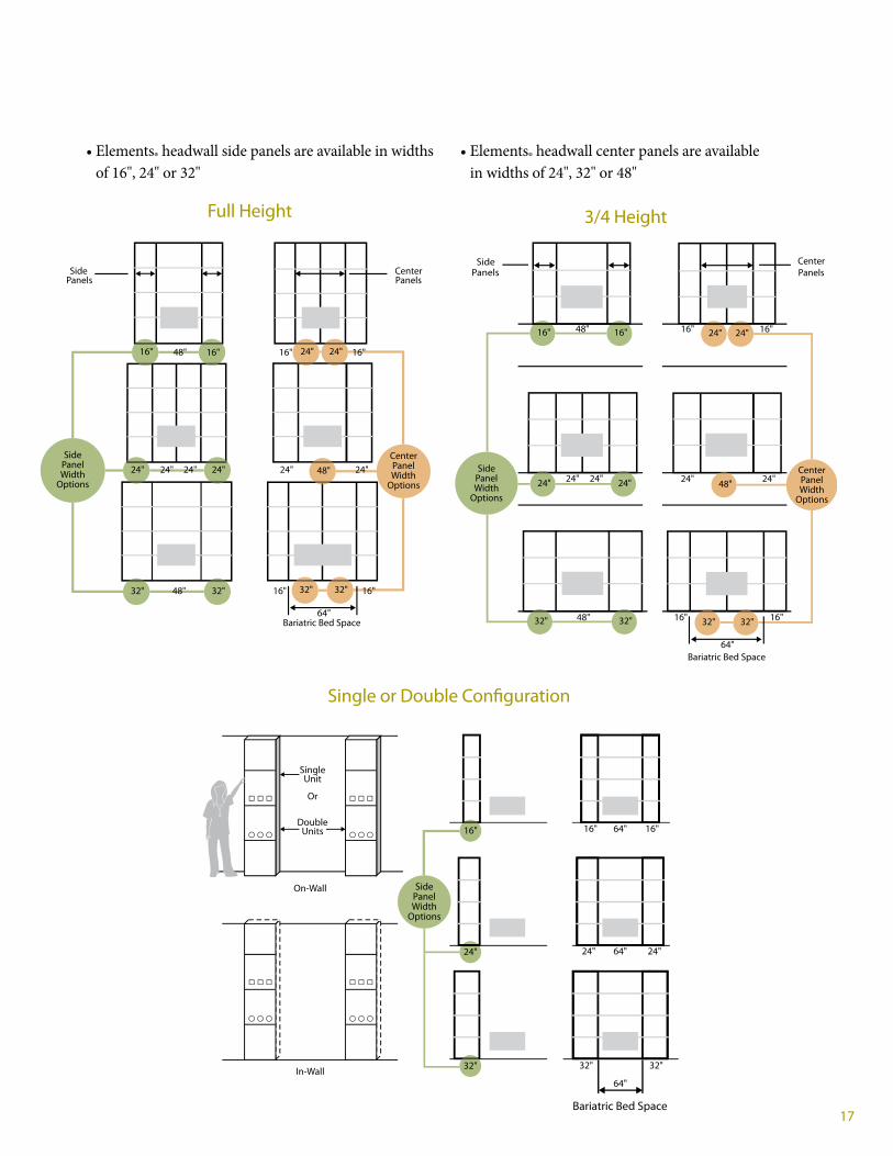
17
Full Height
Single or Double Configuration
3/4 Height
•Elements®headwallsidepanelsareavailableinwidthsof16",24"or32"
•Elements®headwallcenterpanelsareavailableinwidthsof24",32"or48"
Side CenterPanels Panels
16"
24"
32" 16" 32"
64"Bariatric Bed Space
32"48" 32"
24" 24" 24" 24" 48"
16" 16" 24" 24"48"
SidePanelWidth
Options
CenterPanelWidth
Options
24"
16"
16"
Side CenterPanels Panels
16"
16"48"
24" 24" 24" 24"
16" 16"48"
SidePanelWidth
Options
CenterPanelWidth
Options
16"
16"
24" 24"
24"
32" 32"
24" 48"
32" 32"
64"Bariatric Bed Space
In-Wall
16" 16"64"
24" 24"64"
32" 32"
64"
SingleUnit
DoubleUnits
On-Wall
Or
24"
32"
16"
SidePanelWidth
Options
Bariatric Bed Space

18
Height Options
96"
120"HMaximum
Height
72"
18"
120"HMaximum
Height
Frame Assembly Heights= 3" Increments
72"H
48"H
84"H
TheElements®headwallisavailablein6"incrementsfromaminimumheightof48"toamaximumof120".Panelsareavailablein3"incrementheightsfrom6"toamaximumof36"andcanbeconfiguredsymmetricallyorasymmetrically.
Locateclinicalserviceswithinergonomicreachrangeof18"to72"offfinishedfloor.
Elementsheadwallaccessandservicepanelscanbeconfiguredinavarietyofcombinations.
Service Panels (Heights): 6"9"12"15"18"21"24"27"30"33"36"39"42"Access Panels (Heights): 6"9"12"15"18"21"24"27"30"33"36"39"42"

19
Elements® Headwall In-Wall Installed Between Two Stud Walls
18"*
16"*
Frame128"*
Floor Channel by Contractor
Exterior Stud Wall
Ceiling HeightFramed Header
by Contractor
Hill-Rom ElementsFrame Assemblies
End Panel Overhangs Frame and is Scribed and Trimmed by Contractor
Panel to wall Interface by others
Access panel–can only be speci�ed without services
Interior Stud Wall
132"*
24"*
Frame
* Example dimensions only. Actual dimensions will vary depending on your room floor plan.

20
Single Sided In-Wall Elements® Headwall Installed Between Two Stud Walls
BuildingStud Wall
BuildingStud Wall
Acoustic Rated Sheet Rock Installed On Backof Elements Frames by Contractor
Wall to Wall Installation Requires 16’ ElementsFrame Without Services to Adjoin Stud Walls.End Panel Not Intended to be Removed.
• Determine wall to wall opening dimension• Determine number of Elements frame sections based on 16", 24" and 32" standard widths• Elements end frame panels scribed and trimmed to match wall by contractor
Wall to WallCenterline
End Panels Scribed and TrimmedTo Match Wall by Contractor –Wall Interface by Others
End Panel(Not Removable)
16" 24"
18"
128"
132"
Service Panel(Removable)
Sound Insulationby Hill-RomSound
Insulationby Contractor
Interfaceby Others

21
On-Wall Ceiling and Floor Interface
On-Wall Ceiling Interface
• ForOn-Wallinstallations,Elementsshouldbeinstalledafterinteriorwallsandmechanicalsarecompleted.
• Elementsframeworksectionssecuredtostudwall(See Elements® headwall installation guide.)
• Dropceilingedgemoldingattachestoelementsceilingpanel.
On-Wall Floor Interface
• Contractorinstallsfloorchannel.
• Elementsframeworksectionsarealignedandleveledwithfloorlevelers(See Elements® headwall installation guide.)
• Important Note:Elements6"basepanelmustbeinstalledbeforecovedflooringorintegralflashcovemolding.
Sheet Flooring(by contractor)
StandardSheet Rock
StudWall
Side Trim 4½"
Base Cove Molding(by contractor)
Stud Wall
Drop Ceiling Tile
Drop CeilingEdge Molding
Ceiling Panel
Elements Panel
Elements Gap Filler
Elements Base Panel
Side Trim
StandardSheetRock
StudFrame

22
In-Wall Ceiling and Floor Interface35/8" Single Sided and 6" Back-to-Back
Acoustic RatedSheet Rock(by contractor)
Sheet Rock(by contractor)
Single Sided ServicesSingle Sided45 STC
Back-to-back ServicesDouble Sided40 STC
35⁄8"Stud
6"Stud
Acoustic RatedSheet Rock(by contractor)
Finished CeilingHeight (spec’dby architect)
Floor Channel(by contractor)
Base Cove Molding(by contractor)
Sheet Flooring(by contractor)
ElementsFrameChannel(35⁄8")
Floor
Bracing (by contractor)
Header (Typ. 8', 9', 10')(by contractor)
Drop Ceiling Tile
Drop CeilingEdge Molding
Ceiling Panel
Elements Panel
Sound DeadeningMaterial
Elements Gap Filler
Elements Base Panel
In-Wall Ceiling Interface
• ForIn-Wallinstallations,itisrecommendedthatElementsbeinstalledattimeofinteriorframing.
• Contractorconstructsframedheaderwithceilingchannel
• Elementsframeworksectionsinstallintoceilingchannel(See Elements® headwall installation guide.)
• Dropceilingedgemoldingattachestoelementsceilingpanel
In-Wall Floor Interface
• Contractorinstallsfloorchannel
• Elementsframeworksectionsinstallintofloorchannel(See Elements® headwall installation guide.)
• BasecovemoldingorsheetvinylflooringinstalledoverElements6"basepanel
• Important Note:Elements6”basepanelmustbeinstalledbeforecovedflooringorintegralflashcovemolding.

23
In-Wall Ceiling and Floor InterfaceTwo – 35/8" Back-to-Back Elements
Acoustic RatedSheet Rock(by contractor)
Finished CeilingHeight (spec’dby architect)
Floor Channel(by contractor)
Base Cove Molding(by contractor)
Sheet Flooring(by contractor)
ElementsFrameChannel(35⁄8")
Floor
Bracing (by contractor)
Header (Typ. 8', 9', 10')(by contractor)
Drop Ceiling Tile
Drop CeilingEdge Molding
Ceiling Panel
Elements Panel
Sound DeadeningMaterial
Elements Gap Filler
Elements Base Panel
AcousticalSheet Rock(by contractor)
Sheet Rock(by contractor)
Trim Finish(by contractor)
6"Stud
In-Wall Ceiling Interface
• ForIn-Wallinstallations,itisrecommendedthatElementsbeinstalledattimeofinteriorframing.
• Contractorconstructsframedheaderwithceilingchannel
• Elementsframeworksectionsinstallintoceilingchannel(See Elements® headwall installation guide.)
• Dropceilingedgemoldingattachestoelementsceilingpanel
In-Wall Floor Interface
• Contractorinstallsfloorchannel
• Elementsframeworksectionsinstallintofloorchannel(See Elements® headwall installation guide.)
• BasecovemoldingorsheetvinylflooringinstalledoverElements6"basepanel
• Important Note:Elements6"basepanelmustbeinstalledbeforecovedflooringorintegralflashcovemolding.

24
Elements® Headwall In-Wall Installation
1. Contractorconstructsframedheader,floorchannelandadjacentstudframing
2. InstallandsecureElementsframeassembliestoheaderandfloorchannels
3. Contractorbringsgasandelectricaldropstospecifiedlocation
4. ConnectgasandelectricallinestoElementsmanifoldandjunctionbox
5. Completeinstallationofaccesspanels,gapfillersandwallbumpers
6. Completeinstallationofaluminumfinishtrimstripandbasecovemolding
Header Channel
Header Channel
Elements frame assemblies secured to header
Floor Channel
1
2

25
Electrical Drops
Gas Drops
J-Box
Manifold
3
4
6
5
Aluminum Finish Trim
Base Mold

26
Service Capacity TheElements®headwalliscapableofmeetingtheserviceloadingrequirementsofallinpatientcareareasofthehospitalincludingICU,ED,ProgressiveCare,Med-SurgandLabor&Delivery.Inaddition,itsgasmanifoldsystemprovidesthemeanstoeasilyaddgascapacity.
Electrical Capacity
The Elements headwall can support all electrical capacity needs for normal, emergency power and low voltage. Consult your Hill-Rom architectural specialist.
Gas Capacity
Gases Ports Outlets Oxygen 5 10 Air 5 10 Vacuum 6 6
Vacuum
NormalEmergencyLow Voltage
Electrical Junction Box
Gas Manifold
Ports
Flexible hoses
Oxygen
Air

27
Service Connection OptionsTheElements®headwallisconfiguredwithacentersectionallowingforsinglepointconnectionofgasesandelectricals.TheElementsheadwallwithseparateindividualsectionsrequireseparateconnections.
Center section with Single Point Connection
Two separate sections with two-point connections
J Box Manifold
J Box Manifold
Two separate units without center section
Minimum width to house both J Box and gas manifold together
24"
Single-Point Connection
Two-Point Connection

28
On-Wall J Box & Manifold Placement With Nurse Call Pre-Ship Pre-Install
TheElements®headwallon-wallelectricalJboxandgasmanifoldcanbepre-shippedandpre-installedearlyintheconstructionprocessenablingtheplumbingcontractortosavevaluabletimetocompletebrazingandgaslinecertificationbeforetheheadwallisinstalled.
AnursecallstationplacedinthecenterpanelareainfluencesthelocationoftheJboxandgasmanifold.Thenursecallcanbeplacedinthreepossibleareasofthecenterpanel:LeftofCenter,OnCenterlineorRightofCenter.
Right of centerOn Centerline*
* This location not recommended for Nurse Call System with graphic touch panel display
Nurse Call
Left of center
When Elements headwalls with nurse call station is located left or right of the bed centerline
Establishbedlocationandcenterlineinpatientroom.ThiswillserveastheElementsheadwallcenterlineposition.
Installelectricaljunctionboxandgasmanifold8"oncenterfromtheheadwallcenterline.TypicalinstallJbox60"AFFandgasmanifold70"AFF.
Contractorshouldmakeappropriateelectricalandgaslineconnectionspriortoheadwallinstallation.(Refer to Elements headwall installation instructions.)
8" 8"
24" 60" 70"24"
Center Frame Assemblies
Bed and Headwall Centerline
ContractorConnections
Nurse CallLeft of Center
J Box Manifold

29
WhenanursecallstationisspecifiedoncenterlineoftheElementscenterpanel,theJboxandgasmanifoldcenterlinelocationisdifferentcomparedtothenursecalllocatedontheleftorrightsideofthecenterpanel.
Elements® Headwall In-Wall Configuration
Note:theElementsheadwallin-wallconfigurationrequiresthattheJboxandgasmanifoldareinstalledaspartoftheframeandpanelinstallationasthereisnopre-installationmountingprovision.
TheElementsheadwallJboxandgasmanifoldcannotbepre-shippedandpre-installedseparatelyintheElementsheadwallin-wallconfiguration.
When the Elements headwall with nurse call station is located on bed centerline.
Establishbedlocationandcenterlineinpatientroom.ThiswillserveastheElementsheadwallcenterlineposition.
Installgasmanifoldandjunctionbox16"fromheadwallcenterlineand70"AFF.
Locatenursecallonheadwallcenterlineand57"AFF.
Contractorshouldmakeappropriateelectricalandgaslineconnectionspriortoheadwallinstallation.(Refer to Elements headwall installation instructions.)
16"
57" 70"
16"
Center Frame Assemblies
ContractorConnections
Nurse Callon Centerline

30
Equipping the Elements® HeadwallTheElementsheadwalloffersaselectionofoptionsforaccessoriesandsecondarydevicesthatenhancethefunctionalityandincreaseclinicalcapability.Thesecanbeorderedwiththeproductoraddedseparately.
Item Description
Patient Light Read/indirect/safety shut-off Monitor Mount Monitors with up to an 80 lb safe working load Accessory Rail Selection of useful accessories Grab Bar Stainless steel grab bar 16" 24" 32" Bed Bumper Vertical and horizontal IMD Mount Accessory for infusion management device
Patient Light
Monitor Mount
Accessory Rail
Grab Bar
Bed Bumper

31
TheElements®headwalloffersaselectionofoptionalaccessoriesthatcanbeattachedandrepositionedalongahorizontalaccessoryrail.
• Rail Heights – 3" vertical increments beginning 12" off finished floor.
• Rail Widths – standard panel widths of 16", 24", 32", and 48".
• Accessory rails cannot span across adjoining panels.
Whenplanningrailheights,considerthelocationofattachedcomponentsandadjoininggasandelectricaloutletstoavoidblockingoutletsorcreatinginterferenceswithattacheddevices.
See Elements headwall accessory catalog for a complete list of available components. Patient
Monitor
Ceiling
Electrical Outlets
3"
16" 24" 32" 48" Rail Lengths
3" HeightIncrements
18"
72"
Rail Mounted Accessories

32
Options for Bed BumpersAdditionalElements®headwallwallpanelprotectionisavailablewithoptionalbedbumpers.Thisprovidesanadditionalmeasureofprotectionforbedswithtractionequipmentorpatientassistbars.
Horizontal Bumper OptionRecommended for: • VersaCare® bed • CareAssist® bed • Advanta™ 2 bed • If headboard remains stationary*
48"
22"29"
6"
33"
Vertical Bumper OptionRecommended for: • TotalCare® bed • Advanta™ bed • Stryker Go Bed® • If headboard moves up and down*
Optional Center Vertical Bed Bumper
22"29"
6"
* Consult with your Hill-Rom sales associate before final selection. Colors for reference only.
Standard ColorsOther colors available*
Tan
Bone
Linen White
Sea Foam
Mocha
Chinchilla

33
Horizontal & VerticalStandard 3/8" WidthBlack & Aluminum Finish
Horizontal OnlyStandard 3/8" WidthAluminum Finish Only
3/8" �ushconcave
3/8"protruding
Panel
Panel
Panel
Design Options – Panel RevealTheElements®headwallutilizesremovableextrusioninsertstosealthehorizontalandverticalspacebetweenadjoiningpanels.Therearetwostandardwidthinserts:
• 3/8"wideflushconcaveprofileinblackoraluminumfinish
• 3/8"wideprotrudingprofileinaluminumfinish
Thesecanbecombinedorusedindividuallytoacreateuniformornon-uniformgridpattern.

34
Design Options – Laminates & Art Glass
High Pressure Laminates
Elements®headwallpanelsareavailablewithmostcommerciallyavailableHPLfinishes.
Art Glass
Aselectionofartglassmaterialsisavailable.Thesematerialsrequirea16-20weekleadtimefororderingandfabricationthatshouldbeconsideredinspecifyingthisproduct.BecausetheElements®headwallisaULapprovedproduct,certainrestrictionsapply.ConsultaHill-Romsalesassociateforfurtherinformation.
Customized style options can be developed based on volume, lead time and material. Materials must comply with building codes and UL requirements. Consult a Hill-Rom sales associate for further information.
Colors for reference only.
HPL
Art Glass
Art Glass
Astandardselectionoflaminatesareavailableforshortleadtimeordersthatincludesthefollowing:
• 157AntiqueWhite(WilsonArt)• ROKLightOak(WilsonArt)• 705WildCherry(WilsonArt)• 734LimberMaple(WilsonArt)• M07LightNeutral(Nevamar)• 293AlmondLeather(WilsonArt)• 657NaturalMaple(Formica)• WM9HoneyMaple(PioneerPlastics)• MOKEnglishOak(WilsonArt)• 93NLatteWalnut(Formica)

35
Design Options – Art Glass (cont.)
Elements® Headwall Art Glass Design Options
BelowisabriefsummaryoftheartglassoptionsavailableonElementsheadwalls.Theseoptionsarebasedonregulatoryrequirements.Non-standardoptionsareevaluatedonacasebycasebasisandwilleffectleadtime.
Art Glass manufacturers: • 3Form–www.3form.com• Lumicor–www.lumicor.com• Designtex–www.designtex.com
Art Glass Resinbymanufacturer:• 3Form–VariaEcoresin• Lumicor–Lumiform• Designtex–Fusion
Art Glass Texture Artglassislimitedtosmoothexteriorsurfacetexturesforcleanability.However,therearemultiplefinishesavailable.
Art Glass Gauges:1/8"-3/8"forall3manufacturers
Art Glass Gaugeisdeterminedbythematerialorpatternbeingplacedinsidetheglass.• Forexample,3Formoffersapatterncalled“riverrock.”Thispatternactuallytakesrocksandencasesthemintheartglass.Becauseofthis,theminimumgaugeofthematerialis1".Since1"isgreaterthanour3/8"maximumwecannotusethispatternwithoutconductingadditionalregulatorytesting.
Mounting Methods • Standoff Mounting–AnygaugeofartglasscanbemountedonstandoffstoanElementspanel.Anythinggreaterthan1/4"gaugeMUSTbemountedonstandoffs.
• Surface Mounting-Ifthecustomerwantsapaintedfinishbehindtheartglass,wecanuseaonepieceservicepaneltomounttheglass.Thiswillallowthecustomertochoosepatternsingaugesof1/4".Thisshouldcovermostoftheselectionsyouwillsee.Theglasswillusesurfacemountedhardwaretoattachtheglasstothepanel—noadhesiveisused.IfthecustomerwantsanHPLbehindtheart
glass,theymustthenmountitonanaccesspanelfromourvendor.Thisrequires1/8"gaugeartglass.Noneofthemanufacturersadvertisethis;however,theydevelopeditforus.Theymustbecontacteddirectlytodetermineifthepatterndesiredcanbeproducedinthe1/8"gauge.Mostoftheorganicpatterns(grass,leaves,mesh,flatbamboo,etc.)canbeproducedinthisgauge.Anythingwithsignificantthickness(rocks,twigs,etc.)cannotbeproducedinthisgauge.
Standard options and what their limitations are:• Artglassiscurrentlynotavailableonpanelswithserviceprovisions(gas,electric,data)
• Artglassnotavailableinisolatedpowerapplications
.160" thick art glass pros and cons: • PRO–ItismountedtoawoodpanelsoitcanhaveanyHPLcolorandpatternonthebackpanelbehindtheartglassifyoudesire.
• CON–Limitedartglasspatternsareavailableinthisthicknessbasedonmaterialandcomposition.
* Maximum standard size is 48" wide x 42" tall
.250" thick art glass pros and cons: • PRO–Itisavailableinmostartglasspatterns.• CON–Ithastomounttoasteelbackpanelwhichispaintedwarmwhite.Inotherwords,youhavenochoiceinbackgroundcolorunlessyousubmitaspecialtochangepaintcolor.HPLisnotavailableatallinthisoptionbecauseofweldstudsusedforartglassmounting.
* Maximum standard size is 48" wide x 30" tall.

36
Customized style options can be developed based on volume, lead time and material. Materials must comply with building codes and UL requirements. Consult a Hill-Rom sales associate for further information.
Colors for reference only.
Design Options – ¾ Height Headwall Top Cap
TheElements®headwall¾heighton-wallheadwallisavailablewithaselectionoftopcapstylesmanufacturedinwoodorHPL.Corian™brandsolidsurfacematerialisalsoavailableasacustomoption.
Wood Top Caps are available in the following standard stains:
6.395"
Length dimensionsvary based on
headwall dimensions
Top
Transitional
Contemporary
Profile
Top
Profile
2.651"
2.063"
Length dimensionsvary based on
headwall dimensions
4.395"
1.5"
Top Cap
Light Oak Natural MapleWild Cherry Colonial CherryMedium Oak Honey MapleMontana Walnut Dark Cherry

37
On-Wall Side Trim
In-Wall Aluminum Finish Trim Strip
ForOn-Wallinstallations,thesidesoftheheadwallarefinishedwithasidetrimthatmatchesthefrontpanels.
ForIn-Wallinstallations,theseambetweentheElements®headwallpanelsandtheadjoiningstudwalliscoveredwithanaluminumfinishtrimstrip.
Dry Wall
Elements Panel
Elements FrameChannel (35⁄8" or 6")
ElementsGap Filler
SideTrim
Stud Wall
Elements Panel
Elements FrameChannel (35⁄8")
Elements Gap Filler
Aluminum FinishTrim
Dry Wall
Dry Wall
FinishTrim
Stud Wall
Frame

38
Building the Elements® Headwall System – Cabinet Options
ElementscabinetoptionsintegrateclinicalworkflowsupportwithElementsheadwallservices,aswellasprovideaccommodationsforfamilyandvisitors.
• Buildandcustomizeyourheadwallsolutionwithanadaptablebuildingblocksystem
• Elementsheadwallsprovideacomprehensiveselectionofcabinetandcubbyoptionsthatcanbetailoredtoavarietyofneeds,configurationsandaesthetics.
• TheElementscabinetrysystemworksseamlesslywiththeElementsheadwallframeandpanelsystem.
• Withappropriateheadwallplanning,cabinetryoptionscanbedesignedintoyourElementsheadwalltodayoraddedtoyourheadwallovertimeasadditionalrequirementsemerge.

39
Workflow Module Options
Elements Frame
Cabinet Mounts
Countertop
WorkflowModules
Drawer Cabinet
Door Cabinet
Frame Mounted Cabinet OptionsElementscabinetryoptionsaredesignedtoeasilymountontotheElementsframeassembly.
ElementsWorkflowModulessitflushintotheheadwallandprovidethecaregiverwithimportantstorageandhygieneoptionsatthepointofcare.
Glove/Gel Module Sphyg Module
Glove Box Module
Sharps Module
Glove/BP/CuffGlove/Ambu Bag
Available in 24" & 32" widths Available in 16, 24" & 32" widths Available in 24" & 32" widths
Available in 24" & 32" widths Available in 16, 24" & 32" widths Available in 24" & 32" widths
16" Orientation 24" & 32" Orientation
16" Orientation 24" & 32" Orientation

40
Concealment48", 60" - 72"
Cubby Cube
Door/Shelves
Wall Services18" - 42"
Lift Motor
Elements Cabinet Matrix
Drawer
Drawer/Door
Garage Cabinet
Wardrobe Closet Lift Sling Storage Top Filler
Toe Kick
18" - 42" 18" - 42"
18" - 42" 18" - 42"
18" - 42"
24" - 42"
60" - 72" 24", 27", 30"
30" - 42"
Elements provides a selection of 817 Cabinetry & Workflow options based on function and size combinations. Most options are available in 16", 24", & 32" widths and 8", 14", & 24" depths.
Available Heights shown below in 3" increments unless otherwise specified.
6", 9"
Not available in 8" depth or 16" width
Not available in 8" depth or 16" width
Not available in 8" depth
6", 9"
Not available in 8" depth
Valence6", 9", 12, 18"
Widths available from 16 - 128" x 8" incrementsCall for lighting options
Countertop
Widths available from 16 - 128" x 8" increments6" Backsplash
Not available in 8" depth or 16" width
Also available as a 12" Ht. single drawer
Cabinet OptionsElementsheadwallprovidesaselectionof817cabinetryandcubbyoptionsbasedonfunctionandsizecombinations.Mostoptionsareavailablein16",24"and32"widthsand8",14"and24"depths.
Availableheightsshownbelowin3"incrementsunlessotherwisespecified.

41
Glove/Gel Module
Valence Door/Shelves
Drawer
Toe Kick
Countertop

42
Cabinet Depth and Concealment of Clinical Equipment
5 5⁄8" 11 5⁄8" 21 5⁄8"
7 ¼" 13 ¼" 23 ¼"
Flowmeter
Sliding DoorSuction Regulator
Suction Canister
Fetal Monitor
8" Cabinet 14" Cabinet 24" Cabinet
Aspecial17"depthisavailableontheLiftMotorcabinettoaccommodatethemostcommonLiko®patientliftmotorsinasinglerailconfiguration.TheLikotraverserailconfigurationiscompatiblewiththe14"LiftMotorcabinet.
The 8" depth allows for storage and concealment of most flowmeters but does not allow for concealment of suction regulators or canisters. Drawer cabinets are not available in this depth.
The 14" depth allows for storage and concealment of the most common airway equipment such as flowmeters, suction regulators, canisters, and manometers. Additionally, this depth allows for concealment of some types of patient monitoring, and charting equipment. Always check manufacturer’s specifications for compatibility.
The 24" depth allows for storage of all the above and can conceal most fetal monitors, most computer charting equipment and other OB equipment.

43
Cabinet Rules
• 3/8"ProtrudingGapFillerisnotcompatiblewithcabinetoptions.
• CabinetsorSoffitscannotbeplacedoverthecenterbedarealowerthan84"abovefinishedfloor.
• CountertopoptionsmustmounttothetopofacabinetoptionandisprovidedwithabacksplashthatisequivalenttotheheightofastandardElements®6"panel.
• Cabinetsarenotmountedtothefloor;theyarehungontheElementsframework.Atoekickoptionisavailabletogivetheillusionthatthecabinetsaresittingonthefloor.
• Acountertop,backsplash,andwallpanelarerequiredwhenmountingshallowcabinetsabovedeepercabinets.Deepercabinetscanbeplaceddirectlyaboveshallowercabinets.
• Cabinetswidthsmatchtheframetowhichtheyareattached.
• Flushclinicalmodulesinbacktobackheadwallconfigurationsneedtobeevaluatedforhose/conduitroutingonacasebycasebasis.
• Whenplanningaheadwallwithcabinetsoneithersideofthebed,considerbedsiderailmotion.Hill-Rom®bedsrequiremorethan48"ofwidthtoallowforsiderailswingonmostofitsbeds.Usea56"widecenter(2-16"frames+1-24"frame)or64"center(2-32"framesor4-16"frames).Bedswithclockingrailsaregenerallycompatiblewitha48"centerwidth.Also,headwallswithcabinetsononlyonesideofthebedcanusea48"centerwidthaslongasthebedcanbeplacedslightlyoffcenterwheninuse.
• Whenplanningspaceforflowmeters,suctioncanisters.monitors,andotherequipmentinsidetheconcealmentcabinet,makesuretofirstacquireclinicalinputfromthefacility.Newtechnologyandequipmentcandramaticallychangethespacerequired.
• BariatricLiko®patientliftsystemsandallnon-Likosystemsneedtobeverifiedforproperfitandfunctiononacasebycasebasis.

44
Cabinet Dimensions
Cabinet Widths Heights Depths
Safe Working Load
Frame-mounted Cabinets
Concealment1 16", 24", 32" (406 mm, 610 mm, 813 mm) 48", 60", 63", 66", 69", 72" (1219 mm, 1524 mm, 1600 mm, 1676 mm, 1752 mm, 1829 mm)
8", 14", 24" (203 mm, 356 mm, 610 mm) 180
Services cabinet1 16", 24", 32" (406 mm, 610 mm, 813 mm) 18", 21", 24", 27", 30", 33", 36", 39", 42" (457 mm, 533 mm, 610 mm, 686 mm, 762 mm, 838 mm, 914 mm, 991 mm, 1067 mm)
8", 14", 24" (203 mm, 356 mm, 610 mm) 2003
Cubby1 16", 24", 32" (406 mm, 610 mm, 813 mm) 18", 21", 24", 27", 30", 33", 36", 39", 42" (457 mm, 533 mm, 610 mm, 686 mm, 762 mm, 838 mm, 914 mm, 991 mm, 1067 mm)
8", 14", 24" (203 mm, 356 mm, 610 mm) 2003
Door with shelves1 16", 24", 32" (406 mm, 610 mm, 813 mm) 18", 21", 24", 27", 30", 33", 36", 39", 42" (457 mm, 533 mm, 610 mm, 686 mm, 762 mm, 838 mm, 914 mm, 991 mm, 1067 mm)
8", 14", 24" (203 mm, 356 mm, 610 mm) 2003
Drawer/door cabinet1 16", 24", 32" (406 mm, 610 mm, 813 mm) 24", 27", 30", 33", 36" (610 mm, 686 mm, 762 mm, 838 mm, 914 mm) 14", 24" (356 mm, 610 mm) 200
Garage cabinet1 16", 24", 32" (406 mm, 610 mm, 813 mm) 30", 33", 36", 39", 42" (762 mm, 838 mm, 914 mm, 991 mm,1067 mm) 8", 14", 24" (203 mm, 356 mm, 610 mm) 200
Lift motor1 24", 32" (610 mm, 813 mm) 24", 27", 30", 33", 36", 39", 42" (610 mm, 686 mm, 762 mm, 838 mm, 914 mm, 991 mm, 1067 mm)
14", 17", 24" (356 mm, 432 mm, 610 mm) 200
Lift sling storage2 24", 32" (610 mm, 813 mm) 24", 27", 30" (610 mm, 686 mm, 762 mm) 14", 24" (356 mm, 610 mm) 200
Cube cabinet2 16", 24", 32" (406 mm, 610 mm, 813 mm) 18", 21", 24", 27", 30", 33", 36", 39", 42" (457 mm, 533 mm, 610 mm, 686 mm, 762 mm, 838 mm, 914 mm, 991 mm, 1067 mm)
14", 24" (356 mm, 610 mm) 2003
Drawer cabinet2 16", 24", 32" (406 mm, 610 mm, 813 mm) 24", 27", 30", 33", 36" (610 mm, 686 mm, 762 mm, 838 mm, 914 mm) 14", 24" (356 mm, 610 mm) 1903
Wardrobe closet2 24", 32" (610 mm, 813 mm) 60", 63", 66", 69", 72" (1524 mm, 1600 mm, 1676 mm, 1752 mm, 1829 mm)
14", 24" (356 mm, 610 mm) 200
Countertops, Toe Kick, Top Filler, Valance
Valance 16" - 128" (406 - 3251 mm) in 8" (203 mm) increments
6", 9", 12", 15", 18" (152 mm, 229 mm, 305 mm, 381 mm, 457 mm) 8", 14", 24" (203 mm, 356 mm, 610 mm) N/A
Countertop 16" - 96" (406 - 2438 mm) in 8" (203 mm) increments
6" (152 mm) backsplash 8", 14", 24" (203 mm, 356 mm, 610 mm) N/A
Toe kick 16", 24", 32" (406, 610, 813 mm) 6" (152 mm) 5", 11", 21" (127 mm, 279 mm, 533 mm) N/A
Top filler 16", 24", 32" (406 mm, 610 mm, 813 mm) 6", 9" (152 mm, 229 mm) 8", 14", 24" (203 mm, 356 mm, 610 mm) N/A
Workflow Modules
Glove 16" (406 mm) 24", 32" (610, 813 mm) 24" (610 mm) 18" (457 mm) 4" (102 mm)
Sphyg 16" (406 mm) 24, 32 (610 mm, 813 mm) 24" (610 mm) 18" (457 mm) 4" (102 mm)
Sharps 24", 32" (610 mm, 813 mm) 24", 30 (610 mm, 762 mm) 4" (102 mm)
Glove/gel combination 24", 32" (610 mm, 813 mm) 24" (610 mm) 4" (102 mm)
Glove/BP cuff combination 24", 32" (610 mm, 813 mm) 24" (610 mm) 4" (102 mm)
Glove/Ambu bag combination
24", 32" (610 mm, 813 mm) 24" (610 mm) 4" (102 mm)
1 Services are available in the back face of the cabinet.2 Services are not available in the back face of the cabinet.3 Safe Working Load for 18" (457 mm) heights is 172.5; safe working load for 12" (305 mm) heights is 115. Safe working load for other heights is 200.
Cabinetry options and workflow modules can be mixed and matched per client requirements. For configuration purposes, ensure that the cabinet width matches that of the Elements frame; for example, use a 24" Elements frame for 24" cabinets.

45
Codes and Standard RequirementsApplicable Standards
American National Standards Institute (ANSI)/Underwriters Laboratories (UL)–ANSI/UL514AMetallicOutletBoxes
American Society of Mechanical Engineers (ASME)–ASMEB16.22WroughtCopperandCopperAlloySolderJointPressureFittings
ASTM International• ASTME90StandardTestMethodforLaboratoryMeasurementofAirborneSoundTransmissionLossofBuildingPartitionsandElements
• ASTME413ClassificationforRatingSoundTransmission
Compressed Gas Association (CGA)• CGA–G-4.1CleaningEquipmentforOxygenService• CGAV-5DiameterIndexSafetySystem(Non-interchangeableLowPressureConnectionsforMedicalGasApplications)
National Fire Protection Association (NFPA)• NFPA70NationalElectricalCode(NEC)• NFPA99HealthCareFacilities
Underwriters Laboratories Inc. (UL) –UL1047IsolatedPowerSystemsEquipment

Hill-Rom reserves the right to make changes without notice in design, specifications and models . The only warranty Hill-Rom makes is the express written warranty extended on the sale or rental of its products .
©2013 Hill-Rom Services, Inc . ALL RIGHTS RESERVED .
ORDER NUMBER 167229 rev 2 E 10/07/2013 ENG – US
Zinc Number US-AC-1013-0474
www.hill-rom.com
USA 800-445-3730 CANADA 800-267-2337