design and perpendicular to grain tensile ... design and stress analysis of regular double-tapered...
TRANSCRIPT
Structural
Mechanics
HENRIK DANIELSSON
DESIGN AND PERPENDICULAR TOGRAIN TENSILE STRESS INDOUBLE-TAPERED GLULAM BEAMS

Denna sida skall vara tom!

Copyright © 2010 by Structural Mechanics, LTH, Sweden.Printed by Wallin & Dalholm Digital AB, Lund, Sweden, May, 2010 (Pl).
For information, address:
Division of Structural Mechanics, LTH, Lund University, Box 118, SE-221 00 Lund, Sweden.Homepage: http://www.byggmek.lth.se
Structural MechanicsDepartment of Construction Sciences
ISRN LUTVDG/TVSM--10/7159--SE (1-23)ISSN 0281-6679
DESIGN AND PERPENDICULAR TO
GRAIN TENSILE STRESS IN
DOUBLE-TAPERED GLULAM BEAMS
HENRIK DANIELSSON

Abstract
Design and stress analysis of regular double-tapered beams and double-tapered beamswith a flattened apex region is considered, focusing on perpendicular to grain tensilestress in apex region. Double-tapered beams with flattened apex region are analyzedsince the geometry is such that the perpendicular to grain tensile stress may be reducedcompared to a regular double-tapered beam of corresponding geometry.
The Eurocode 5 design criteria for regular double-tapered beams regarding bendingstress, shear stress and perpendicular to grain tensile stress are reviewed. Design withrespect to perpendicular to grain tensile stress is based on an approximate solutionfor maximum stress and Weibull type considerations for influence of size of stressedvolume and heterogeneity in stress distribution on the strength.
The maximum stress, the size of the stressed volume and heterogeneity in stressdistribution are analyzed by linear elastic finite element analysis for regular double-tapered beams and for double-tapered beams with a flattened apex region. For bothgeometry types, loading by a uniformly distributed load and point loads in the twoquarter points of the beam is considered.
Based on the FE-analysis, proposals for design criterion with respect to perpen-dicular to grain tensile stress are also presented. The proposals consist of modificationsof the Eurocode 5 design approach for regular double-tapered beams.
Keywords: glulam, tapered, perpendicular, stress, strength, design, Weibull

Sammanfattning
Dimensionering och spanningsanalys av sadelbalkar behandlas, med tyngdpunkt patvardragspanning i nockpartiet. Dimensioneringsvillkor enligt Eurocode 5 och till vissdel aven deras bakgrund presenteras och ett exempel av dimensionerande last med han-syn till bojning, skjuvning samt tvardrag presenteras. Exemplet visar att skjuvninghar avgorande betydelse for dimensionering av sadelbalkar enligt Eurocode 5, vilketberor pa den nyligen introducerade reduktionen av skjuvbarformaga med hansyn tillbefintliga sprickor. Bortses fran denna reduktion ar tvardragspanning i nockpartietofta dimensionerande for sadelbalkar, med undantag for sadelbalkar med liten lutningda istallet bojning kan vara dimensionerande. Dimensionering med hansyn till tvar-dragspanning ar baserat pa ett approximativt uttryck for maximal spanning i nock-partiet samt pa inflytande av storleken pa tvardragsbelastad volym och heterogeniteti spanningsfordelning pa barformagan.
Linjarelastisk spanningsanalys av konventionalla sadelbalkar och sadelbalkar medtillplattad hjassa presenteras. Sadelbalkar med tillplattad hjassa analyseras eftersomgeometrin ar sadan att tvardragspanningen kan minskas jamfort med spanningen imotsvarande sadelbalk av konventionellt utforande. Resultat av spanningsanalysenpresenteras i form av storlek pa maximal spanning, storlek pa tvardragsbelastad volymsamt heterogenitet i spanningsfordelningen. For balkgeometrier med tillplattad hjassaerholls betydligt lagre varden pa maximal tvardragspanning jamfort med motsvarandesadelbalk av konventionell geometri. Vidare erholls betydande skillnader i maximaltvardragspanning och aven betydande skillnader i storlek pa tvardragsbelastad volymmellan olika lastfall, vilka i denna analys var jamnt utbredd last och belastning av tvapunktlaster i balkens fjardedelspunkter.
Enligt Eurocode 5 far dimenionerande tvardragspanning reduceras for lastfall medjamnt utbredd tryckande last som verkar i balkens overkant. Motsvarande reduktionfar dock inte goras av storleken pa den tvardragsbelastade volymen, som inverkar padimensionerande hallfasthet. Den i Eurocode 5 antagna storleken av tvardragsbelastadvolym ar dock mindre, i vissa fall betydligt mindre, an belastad volym enligt presen-terad spanningsanalys for alla betraktade geometrier och lastfall. Trots att storlekenpa tvardragsbelastad volym underskattas erhalls relativt god overensstammelse mel-lan Eurocode 5 och presenterad spanningsanalys for det kombinerade inflytandet avbelastad volym och heterogenitet i spanningsfordelning. Detta beror pa att aven het-erogeniteten i spanningsfordelningen underskattas enligt Eurocode 5.
Tva forslag pa dimensioneringsvillkor med hansyn till tvardragspanningar presen-teras. Dessa forslag ar bada baserade pa nuvarande dimensioneringsvillkor for konven-tionella sadelbalkar i Eurocode 5 med modifikationer av de approximativa uttrycken formaximal spanning, storlek pa tvardragsbelastad volym och inflytande av heterogenitet ispanningsfordelning. Foreslagna modifieringar ar endast baserade pa den presenteradespanningsanalysen och ar saledes inte anpassade till resultat av experimentella testerpa nagot vis.


Contents
1 Introduction 3
2 Approximate stress solutions 4
3 Weibull theory 5
4 Review of code design criterion 54.1 Eurocode 5 . . . . . . . . . . . . . . . . . . . . . . . . . . . . . . . . . 64.2 Limtrahandbok . . . . . . . . . . . . . . . . . . . . . . . . . . . . . . . 74.3 Code design example . . . . . . . . . . . . . . . . . . . . . . . . . . . . 8
5 Linear elastic finite element stress analysis 9
6 Proposals for code design criterion 146.1 Design proposal 1 . . . . . . . . . . . . . . . . . . . . . . . . . . . . . . 146.2 Design proposal 2 . . . . . . . . . . . . . . . . . . . . . . . . . . . . . . 17
7 Concluding remarks 20
References 21
1


1 Introduction
One of the most basic and most used structural elements is a simply supported beamwith constant cross section carrying transverse load in bending, with shear- and normalstress distributions easily found from conventional engineering beam theory. The beamgeometry can however be modified by shifting material volume from low to high stressregions to increase the efficiency of material use and maybe equally important to achievea geometry with other desired qualities. One example is a double-tapered beam, wherethe beam geometry better resembles the bending stress distribution for many loadcases and the geometry further gives a natural roof inclination. Modifying the beamgeometry in this way does however also alter the internal shear- and bending stressdistributions and furthermore introduces perpendicular to grain (hereafter abbreviatedperp-to-grain) tensile stress in the apex region.
This report concerns design and stress analysis of double-tapered beams, focusingon finite element stress analysis of the perp-to-grain tensile stress in the apex region.Design according to Eurocode 5 and Limtrahandbok regarding bending, shear and andperp-to-grain tensile stress are reviewed and the approximate solutions, on which designregarding bending and perp-to-grain tensile stress are based, are also briefly reviewed.Design with respect to perp-to-grain tensile stress is further based on Weibull typeconsiderations of the influence of size of stressed volume and heterogeneity in stressdistributions on the strength.
Two geometrical modifications according to Figure 1 of a regular double-taperedbeam, aimed at reducing the perp-to-grain tensile stress, were considered. Introducinga vertical slit at the beam apex was in a preliminary analysis found to increase bothstress magnitude and size of stressed volume and this approach was hence abandoned.In the following, only regular double-tapered beams and double-tapered beams with a”flattened” apex region are considered. Stress magnitude, size of the stressed volumeand heterogeneity in stress distribution are analyzed by linear elastic finite elementanalysis and results are compared to corresponding values according to the Eurocode 5design criterion. Proposals for design criterion, based on modifications of the Eurocode5 design criterion, are also presented.
Double-tapered beam with flattened apex region
Regular double-tapered beam
Double-tapered beam with veritcal slit at beam apex
Figure 1: Geometrical modifications aimed at reducing perp-to-grain tensile stress
3
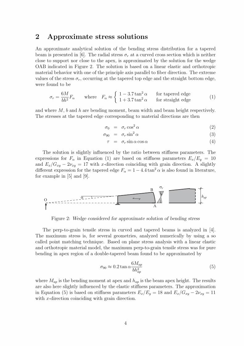
2 Approximate stress solutions
An approximate analytical solution of the bending stress distribution for a taperedbeam is presented in [6]. The radial stress σr at a curved cross section which is neitherclose to support nor close to the apex, is approximated by the solution for the wedgeOAB indicated in Figure 2. The solution is based on a linear elastic and orthotropicmaterial behavior with one of the principle axis parallel to fiber direction. The extremevalues of the stress σr, occurring at the tapered top edge and the straight bottom edge,were found to be
σr =6M
bh2Fα where Fα ≈
1− 3.7 tan2 α for tapered edge1 + 3.7 tan2 α for straight edge
(1)
and where M , b and h are bending moment, beam width and beam height respectively.The stresses at the tapered edge corresponding to material directions are then
σ0 = σr cos2 α (2)
σ90 = σr sin2 α (3)
τ = σr sinα cosα (4)
The solution is slightly influenced by the ratio between stiffness parameters. Theexpressions for Fα in Equation (1) are based on stiffness parameters Ex/Ey = 10and Ex/Gxy − 2νxy = 17 with x-direction coinciding with grain direction. A slightlydifferent expression for the tapered edge Fα = 1− 4.4 tan2 α is also found in literature,for example in [5] and [9].
α hapO
A
Bσr
Figure 2: Wedge considered for approximate solution of bending stress
The perp-to-grain tensile stress in curved and tapered beams is analyzed in [4].The maximum stress is, for several geometries, analyzed numerically by using a socalled point matching technique. Based on plane stress analysis with a linear elasticand orthotropic material model, the maximum perp-to-grain tensile stress was for purebending in apex region of a double-tapered beam found to be approximated by
σ90 ≈ 0.2 tanα6Map
bh2ap
(5)
where Map is the bending moment at apex and hap is the beam apex height. The resultsare also here slightly influenced by the elastic stiffness parameters. The approximationin Equation (5) is based on stiffness parameters Ex/Ey = 18 and Ex/Gxy − 2νxy = 11with x-direction coinciding with grain direction.
4
3 Weibull theory
The perp-to-grain tensile strength is for wood strongly dependent on the size of thestressed volume, which can be and often is explained by Weibull theory [10]. Thebasic assumptions in Weibull theory is that the weakest point in a stressed volume isdecisive for the strength and that all material points are equal with respect to statisticalprobability distribution of strength. The global strength is hence size-dependent sincethe strength is limited by the weakest point and the larger the volume the more likelyit is that severe defects are present. In addition to the pure volume influence, thestress distribution also effect strength. Based on the Weibull two-parameter model, arelationship between the strength f valid for a volume Ω with a heterogenous stressdistribution σ(x, y, z) and the reference strength fref valid for a homogeneous stressdistribution in a reference volume Ωref is found to be
f = fref
(Ω
Ωref
)−1/m (1
Ω
∫Ω
(σ(x, y, x)
σmax
)m
dΩ
)−1/m
(6)
where σmax is the maximum of σ(x, y, z) and m is the Weibull shape parameter relatedto the scatter in material strength, see for example [2]. The two last terms represent theinfluence of size of stressed volume and heterogeneity in stress distribution respectively.The relationship is in timber engineering design codes commonly expressed as
f = frefkvolkdis where
kvol =(
ΩΩref
)−1/m
kdis =(
1Ω
∫Ω
(σ(x,y,x)σmax
)m
dΩ)−1/m (7)
where Ωref and m are given constant values related to the reference strength fref . Thevolume Ω and hence also kvol is commonly given as a function of geometry while kdismay be assigned a constant value or may be expressed in terms of geometry and/orload parameters for the specific application.
4 Review of code design criterion
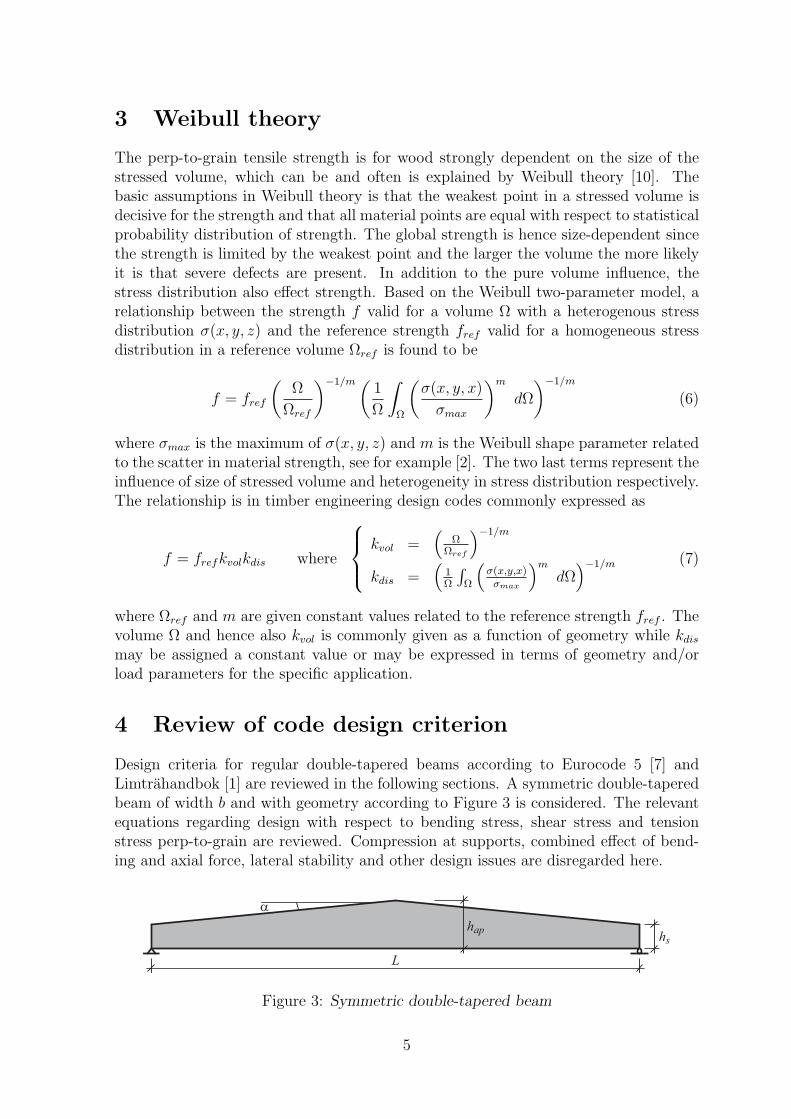
Design criteria for regular double-tapered beams according to Eurocode 5 [7] andLimtrahandbok [1] are reviewed in the following sections. A symmetric double-taperedbeam of width b and with geometry according to Figure 3 is considered. The relevantequations regarding design with respect to bending stress, shear stress and tensionstress perp-to-grain are reviewed. Compression at supports, combined effect of bend-ing and axial force, lateral stability and other design issues are disregarded here.
L
α
haphs
Figure 3: Symmetric double-tapered beam
5
4.1 Eurocode 5
The bending stress at the tapered edge σmα should fulfill
σmα =6M
bh2≤ kmαfm (8)
where fm is the design bending strength and where for tensile stress at tapered edge
kmα =1√
1 +(
fm0.75fv
tanα)2
+(
fmft90
tan2 α)2
(9)
and where for compressive stress at the tapered edge
kmα =1√
1 +(
fm1.5fv
tanα)2
+(
fmfc90
tan2 α)2
(10)
The bending stress at the apex σm should fulfill
σm = (1 + 1.4 tanα+ 5.4 tan2 α)6Map
bh2ap
≤ fm (11)
where Map is the bending moment at the apex.
The shear stress τ should fulfill
τ =3V
2befh≤ fv (12)
where fv is the design shear strength and the effective beam width bef = bkcr where kcris a nationally determined parameter (NDP) related to an assumed strength reductiondue to presence of cracks. The Swedish choice found in Appendix NA [7] is kcr = 0.67.The shear force V may be determined by ignoring loads acting on the upper part of thebeam, from the support and within a distance equal to the beam height at the support.
The perp-to-grain tensile stress σt90 at the apex region should fulfill
σt90 = 0.2 tanα6Map
bh2ap
≤ kdiskvolft90 (13)
kdis = 1.4
kvol = (V0/V )0.2 where V = bh2ap
where ft90 is the design perp-to-grain tensile strength and V0 = 0.01 m3. As a nationallydetermined parameter (NDP), the design value of the perp-to-grain tensile stress σt90
may alternatively be determined according to
σt90 = 0.2 tanα6Map
bh2ap
− 0.6p
b(14)
when there is a uniformly distributed (pressure) load p acting on top of the apex area.The Swedish choice found in Appendix NA [7] is that Equation (14) may be used.
6

4.2 Limtrahandbok
The design criteria in Limtrahandbok are in general consistent with the criteria inEurocode 5, but there are however some exceptions:
• The first difference lies in the criterion for bending, which in Limtrahandbok isexpressed as
σmα = kσα6M
bh2≤ kfαfm (15)
where kσα accounts for the discrepancy in direction (at tapered edge) and inmagnitude (at tapered edge and straight edge) from the linear bending stressdistribution found in a beam of constant cross section
kσα =
1− 4 tan2 α for tapered edge1 + 4 tan2 α for straight edge
(16)
and where kfα accounts for the difference in strength due to the stress componentat an angle to grain according to
kfα =
1
fmfc90
sin2 α+ cos2 αfor compression at tapered edge
1fmft90
sin2 α+ cos2 αfor tension at tapered edge
(17)
• The second difference relates the design with respect to shear stress. In Limtra-handbok, there is no reduction of shear strength with respect to presence of crackas stated in Eurocode 5. Design with respect to shear stress in Limtrahandbokis equal to Equation (12) with kcr = 1.0 and hence bef = b.
• The third difference relates to design with respect to perp-to-grain tensile stress,where in Limtrahandbok nothing is stated relating to reduction of the magnitudein stress due to uniformly distributed load acting on top of the beam. The designperp-to-grain tensile stress is in Limtrahandbok equal to Equation (13) althoughwith 0.1 instead of 0.2, which however is believed to be a misprint.
7

4.3 Code design example
Strength design of double-tapered beams according to Eurocode 5 and Limtrahandbokis in general limited due to either bending stress, shear stress or perp-to-grain tensilestress depending on beam geometry, load configuration and values of material strengths.An illustration of the design value qd according to Eurocode 5 for a symmetric double-tapered beam exposed to a uniformly distributed load q is presented in Figure 4.
The introduction of the reduction factor kcr = 0.67 in Eurocode 5, related to anassumed shear strength reduction due to presence of crack, has a major influence onthe overall design of double-tapered beams. For the geometry and strength propertiesconsidered in Figure 4, the design load qd is limited by shear stress for hap > 1.37 m(α > 1.9o) with the nationally determined parameter kcr = 0.67 .
Disregarding design with respect to shear stress, design is limited due to eitherbending stress or perp-to-grain tensile stress at apex region. For small values of beamapex height hap (small inclination α), the strength is then limit by bending stress attapered edge. Perp-to-grain tensile stress at apex region is decisive for hap > 1.65 m(α > 3.7o) if the reduction due to uniformly distributed load on top of the beam is notaccounted for. The design load qd furthermore decreases with increasing beam apexheight hap.
1 1.5 2 2.5 30
5
10
15
20
25
30
35
40
Beam apex height hap
[m]
Des
ign
valu
e of
uni
form
ly d
istr
ibut
ed lo
ad q
d [kN
/m]
Bendingapex
Bendingtapered edge
Perp. tensionEquation (13)
Shear, kcr
=1.0
Perp. tensionEquation (14)
Shear, kcr
=0.67
2 o 4 o 6 o 8 o 10oα
Figure 4: Design value of uniformly distributed load qd according to Eurocode 5 vs.beam apex height hap for L = 20 m, b = 0.2 m, hs = 1.0 m with design strengthsbased on characteristic strengths for GL28h in [8]; fmk = 28, fc90k = 3.0, fvk = 3.2,ft90k = 0.45 MPa modified according to kmod = 0.8 and γm = 1.25.
8

5 Linear elastic finite element stress analysis
Two-dimensional plane stress finite element analysis was performed in order to inves-tigate magnitude and distribution of the perp-to-grain tensile stress. An orthotropicand linear elastic material model was used with stiffness parameters Ex = 12600 MPa,Ey = 420 MPa, Gxy = 780 MPa and νxy = 0.35 with x-direction coinciding with graindirection.
The analysis comprises beam geometries according to Figure 5; regular double-tapered beams and double-tapered beams with a flattened apex region. The beamlength L = 20 m, beam width b = 0.2 m and beam height at supports hs = 1.0 m wereconsistently used whereas the beam apex heights hap = 1.25, 1.50, 1.75, 2.00, 2.25, 2.50and 2.75 m were considered. For beams with flattened apex region, the length of theflattened part was consistently a = 2hap where hap refers to the theoretical beam apexheight.
Two different load configurations were analyzed for both types of geometry, namelyuniformly distributed load q or two point loads P acting at the quarter points of thebeam length. Results of stress magnitude are based on applied loads q = 20 kN/mor P = 200 kN, which for both cases results in a bending moment at mid span ofMap = 1000 kNm.
L
α
haphs
L
α
haphs
a=2hap
Regular double-tapered beam
Double-tapered beam
with flattened apex
q
P P
q
P P
Figure 5: Beam geometries and load configurations
For convenient presentation of results, the following notation is adopted:
FE-q FE analysis, uniformly distributed load q, regular double tapered beamFE-q-a FE analysis, uniformly distributed load q, flattened double tapered beamFE-PP FE analysis, two point loads P , regular double tapered beamFE-PP-a FE analysis, two point loads P , flattened double tapered beamEC5 Eurocode 5, according to Equation (13)EC5-q Eurocode 5, according to Equation (14)
9
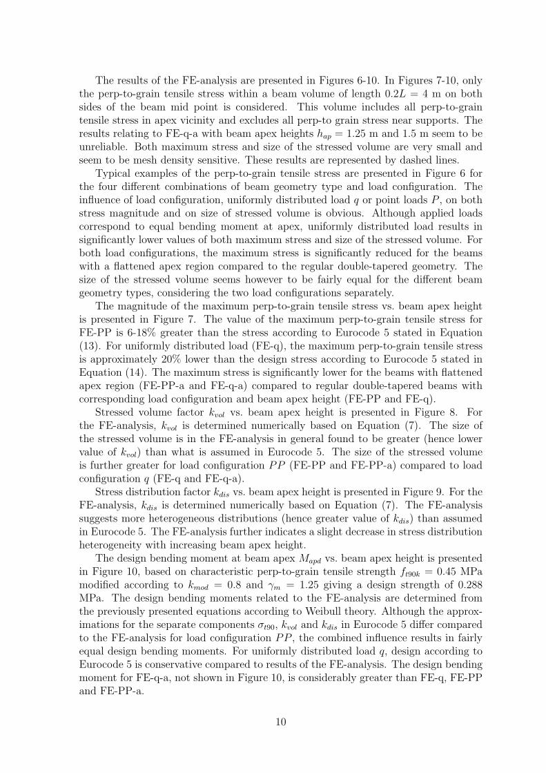
The results of the FE-analysis are presented in Figures 6-10. In Figures 7-10, onlythe perp-to-grain tensile stress within a beam volume of length 0.2L = 4 m on bothsides of the beam mid point is considered. This volume includes all perp-to-graintensile stress in apex vicinity and excludes all perp-to grain stress near supports. Theresults relating to FE-q-a with beam apex heights hap = 1.25 m and 1.5 m seem to beunreliable. Both maximum stress and size of the stressed volume are very small andseem to be mesh density sensitive. These results are represented by dashed lines.
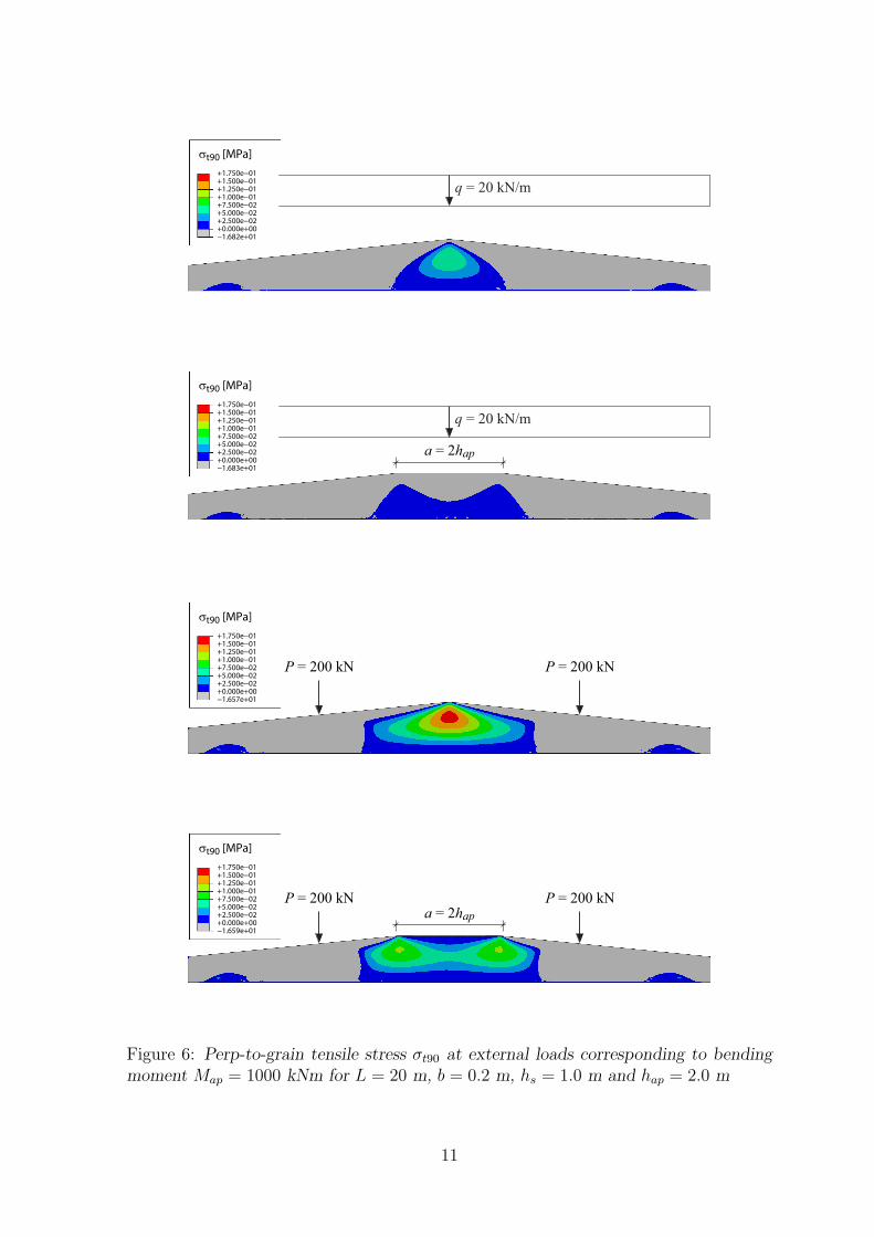
Typical examples of the perp-to-grain tensile stress are presented in Figure 6 forthe four different combinations of beam geometry type and load configuration. Theinfluence of load configuration, uniformly distributed load q or point loads P , on bothstress magnitude and on size of stressed volume is obvious. Although applied loadscorrespond to equal bending moment at apex, uniformly distributed load results insignificantly lower values of both maximum stress and size of the stressed volume. Forboth load configurations, the maximum stress is significantly reduced for the beamswith a flattened apex region compared to the regular double-tapered geometry. Thesize of the stressed volume seems however to be fairly equal for the different beamgeometry types, considering the two load configurations separately.
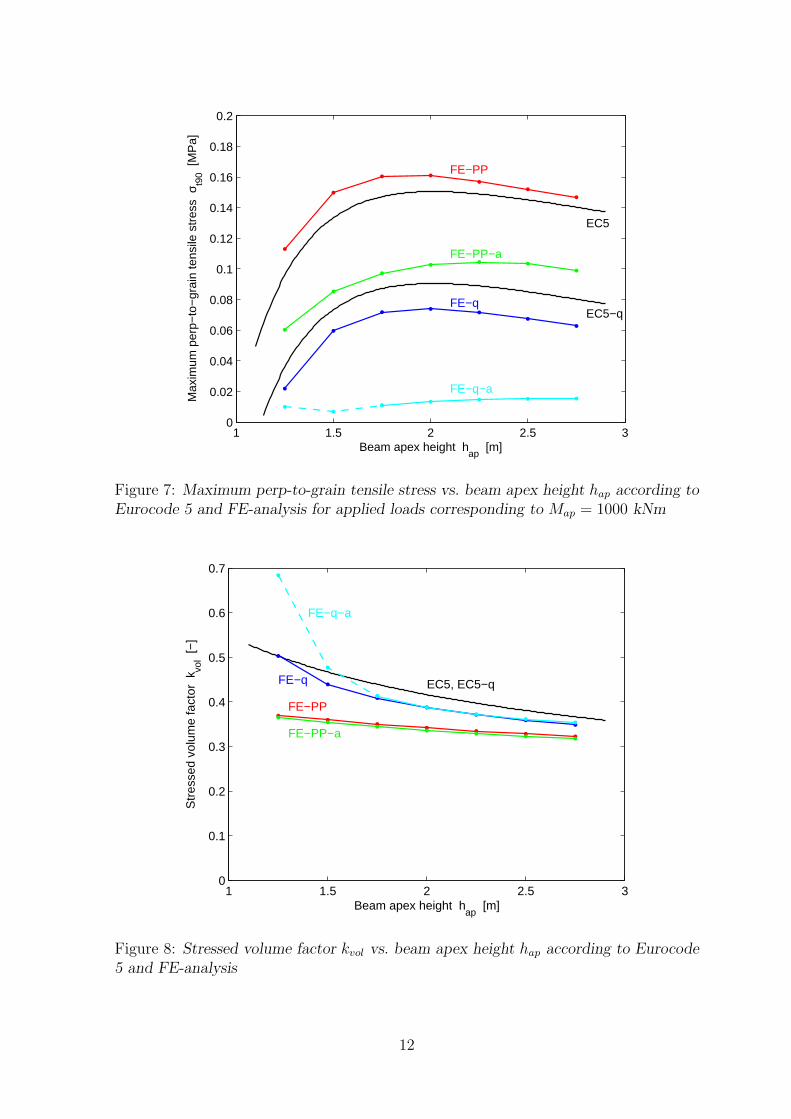
The magnitude of the maximum perp-to-grain tensile stress vs. beam apex heightis presented in Figure 7. The value of the maximum perp-to-grain tensile stress forFE-PP is 6-18% greater than the stress according to Eurocode 5 stated in Equation(13). For uniformly distributed load (FE-q), the maximum perp-to-grain tensile stressis approximately 20% lower than the design stress according to Eurocode 5 stated inEquation (14). The maximum stress is significantly lower for the beams with flattenedapex region (FE-PP-a and FE-q-a) compared to regular double-tapered beams withcorresponding load configuration and beam apex height (FE-PP and FE-q).
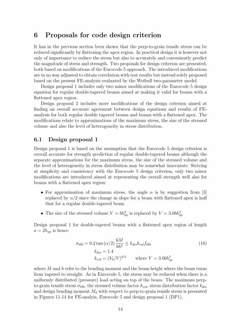
Stressed volume factor kvol vs. beam apex height is presented in Figure 8. Forthe FE-analysis, kvol is determined numerically based on Equation (7). The size ofthe stressed volume is in the FE-analysis in general found to be greater (hence lowervalue of kvol) than what is assumed in Eurocode 5. The size of the stressed volumeis further greater for load configuration PP (FE-PP and FE-PP-a) compared to loadconfiguration q (FE-q and FE-q-a).
Stress distribution factor kdis vs. beam apex height is presented in Figure 9. For theFE-analysis, kdis is determined numerically based on Equation (7). The FE-analysissuggests more heterogeneous distributions (hence greater value of kdis) than assumedin Eurocode 5. The FE-analysis further indicates a slight decrease in stress distributionheterogeneity with increasing beam apex height.
The design bending moment at beam apex Mapd vs. beam apex height is presentedin Figure 10, based on characteristic perp-to-grain tensile strength ft90k = 0.45 MPamodified according to kmod = 0.8 and γm = 1.25 giving a design strength of 0.288MPa. The design bending moments related to the FE-analysis are determined fromthe previously presented equations according to Weibull theory. Although the approx-imations for the separate components σt90, kvol and kdis in Eurocode 5 differ comparedto the FE-analysis for load configuration PP , the combined influence results in fairlyequal design bending moments. For uniformly distributed load q, design according toEurocode 5 is conservative compared to results of the FE-analysis. The design bendingmoment for FE-q-a, not shown in Figure 10, is considerably greater than FE-q, FE-PPand FE-PP-a.
10
σt90 [MPa]
+0.000e+00+2.500e−02+5.000e−02+7.500e−02+1.000e−01+1.250e−01+1.500e−01+1.750e−01
−1.682e+01
q = 20 kN/m
+0.000e+00+2.500e−02+5.000e−02+7.500e−02+1.000e−01+1.250e−01+1.500e−01+1.750e−01
−1.683e+01
a = 2hap
q = 20 kN/m
σt90 [MPa]
+0.000e+00+2.500e−02+5.000e−02+7.500e−02+1.000e−01+1.250e−01+1.500e−01+1.750e−01
−1.657e+01
P = 200 kN P = 200 kN
σt90 [MPa]
+0.000e+00+2.500e−02+5.000e−02+7.500e−02+1.000e−01+1.250e−01+1.500e−01+1.750e−01
−1.659e+01
P = 200 kN P = 200 kNa = 2hap
σt90 [MPa]
Figure 6: Perp-to-grain tensile stress σt90 at external loads corresponding to bendingmoment Map = 1000 kNm for L = 20 m, b = 0.2 m, hs = 1.0 m and hap = 2.0 m
11
1 1.5 2 2.5 30
0.02
0.04
0.06
0.08
0.1
0.12
0.14
0.16
0.18
0.2
Beam apex height hap
[m]
Max
imum
per
p−to
−gr
ain
tens
ile s
tres
s σ
t90 [
MP
a]
EC5−q
EC5
FE−PP
FE−PP−a
FE−q
FE−q−a
Figure 7: Maximum perp-to-grain tensile stress vs. beam apex height hap according toEurocode 5 and FE-analysis for applied loads corresponding to Map = 1000 kNm
1 1.5 2 2.5 30
0.1
0.2
0.3
0.4
0.5
0.6
0.7
FE−q
FE−PP
FE−PP−a
FE−q−a
EC5, EC5−q
Beam apex height hap
[m]
Str
esse
d vo
lum
e fa
ctor
kvo
l [−
]
Figure 8: Stressed volume factor kvol vs. beam apex height hap according to Eurocode5 and FE-analysis
12

1 1.5 2 2.5 30
0.5
1
1.5
2
Beam apex height hap
[m]
Str
ess
dist
ribut
ion
fact
or k
dis [
−]
FE−PP
FE−PP−a
FE−qFE−q−a
EC5, EC5−q
Figure 9: Stress distribution factor kdis vs. beam apex height hap according to Eurocode5 and FE-analysis
1 1.5 2 2.5 30
0.5
1
1.5
2
2.5
3
3.5
4
Beam apex height hap
[m]
Des
ign
bend
ing
mom
ent a
t ape
x M
apd [
MN
m]
FE−PP
FE−PP−a
FE−q
EC5EC5−q
Figure 10: Design bending moment at apex Mapd with respect to perp-to-grain tensilestress vs. beam apex height hap according to Eurocode 5 and FE-analysis
13
6 Proposals for code design criterion
It has in the previous section been shown that the perp-to-grain tensile stress can bereduced significantly by flattening the apex region. In practical design it is however notonly of importance to reduce the stress but also to accurately and conveniently predictthe magnitude of stress and strength. Two proposals for design criterion are presented,both based on modifications of the Eurocode 5 approach. The introduced modificationsare in no way adjusted to obtain correlation with test results but instead solely proposedbased on the present FE-analysis evaluated by the Weibull two-parameter model.
Design proposal 1 includes only two minor modifications of the Eurocode 5 designequation for regular double-tapered beams aimed at making it valid for beams with aflattened apex region.
Design proposal 2 includes more modifications of the design criterion aimed atfinding an overall accurate agreement between design equations and results of FE-analysis for both regular double tapered beams and beams with a flattened apex. Themodifications relate to approximations of the maximum stress, the size of the stressedvolume and also the level of heterogeneity in stress distribution.
6.1 Design proposal 1
Design proposal 1 is based on the assumption that the Eurocode 5 design criterion isoverall accurate for strength prediction of regular double-tapered beams although theseparate approximations for the maximum stress, the size of the stressed volume andthe level of heterogeneity in stress distribution may be somewhat inaccurate. Strivingat simplicity and consistency with the Eurocode 5 design criterion, only two minormodifications are introduced aimed at representing the overall strength well also forbeams with a flattened apex region:
• For approximation of maximum stress, the angle α is by suggestion from [3]replaced by α/2 since the change in slope for a beam with flattened apex is halfthat for a regular double-tapered beam
• The size of the stressed volume V = bh2ap is replaced by V = 3.0bh2
ap
Design proposal 1 for double-tapered beams with a flattened apex region of lengtha = 2hap is hence
σt90 = 0.2 tan (α/2)6M
bh2≤ kdiskvolft90 (18)
kdis = 1.4
kvol = (V0/V )0.2 where V = 3.0bh2ap
whereM and h refer to the bending moment and the beam height where the beam turnsfrom tapered to straight. As in Eurocode 5, the stress may be reduced when there is auniformly distributed (pressure) load acting on top of the beam. The maximum perp-to-grain tensile stress σt90, the stressed volume factor kvol, stress distribution factor kdisand design bending moment Md with respect to perp-to-grain tensile stress is presentedin Figures 11-14 for FE-analyis, Eurocode 5 and design proposal 1 (DP1).
14

1 1.5 2 2.5 30
0.02
0.04
0.06
0.08
0.1
0.12
0.14
0.16
0.18
0.2
DP1
DP1−q
EC5−q
EC5
FE−PP
FE−PP−a
FE−q
FE−q−a
Beam apex height hap
[m]
Max
imum
per
p−to
−gr
ain
tens
ile s
tres
s σ
t90 [
MP
a]
Figure 11: Maximum perp-to-grain tensile stress σt90 vs. hap according to FE-analysis,Eurocode 5 and design proposal 1 for applied loads corresponding to M = 1000 kNm
1 1.5 2 2.5 30
0.1
0.2
0.3
0.4
0.5
0.6
0.7
FE−q
FE−PP
FE−PP−a
FE−q−a
EC5, EC5−qDP1
Beam apex height hap
[m]
Str
esse
d vo
lum
e fa
ctor
kvo
l [−
]
Figure 12: Stressed volume factor kvol vs. beam apex height hap according to FE-analysis, Eurocode 5 and design proposal 1
15

1 1.5 2 2.5 30
0.5
1
1.5
2 FE−PP
FE−PP−a
FE−qFE−q−a
DP1, EC5, EC5−q
Beam apex height hap
[m]
Str
ess
dist
ribut
ion
fact
or k
dis [
−]
Figure 13: Stress distribution factor kdis vs. beam apex height hap according to FE-analysis, Eurocode 5 and design proposal 1
1 1.5 2 2.5 30
0.5
1
1.5
2
2.5
3
3.5
4
FE−PP
FE−PP−a
FE−q
EC5EC5−q
DP1
Beam apex height hap
[m]
Des
ign
bend
ing
mom
ent
Md [
MN
m]
Figure 14: Design bending moment Md with respect to perp-to-grain tensile stressvs. beam apex height hap according to FE-analysis, Eurocode 5 and design proposal 1
16
6.2 Design proposal 2
Design proposal 2 is a unified design criterion for both regular double-tapered beamsand beams with flattened apex region based on the assumption that Weibull theory isapplicable and that the FE-analysis is representative for various beam geometries andload configurations. The proposed design criterion is based on the Eurocode 5 approachwith modifications including more accurate approximations of the maximum stress, thesize of the stressed volume and the level of heterogeneity in stress distribution:
• As in design proposal 1, the angle α is replaced by α/2 for beams with flattenedapex region as suggested by [3]
• The constant 0.20 is replaced by 0.22 for better correlation of stress magnitude
• The factor kdis = 1.4 is replaced by kdis = 1.6 to better represent the heterogeneityin stress distribution
• The factor kvol is modified by replacing the approximation for size of the stressedvolume V = bh2
ap by V = 0.3Lbh+ 0.25Lb(hap − hs)
• For beams with a uniformly distributed (pressure) load acting on top of the beam,a greater reduction of the maximum stress than stated in Eurocode 5 is allowedand in addition a reduced size of the stressed volume V = 0.25Lb(hap − hs) mayalso be assumed
Design proposal 2 for regular double-tapered beams and double-tapered beams with aflattened apex region of length a = 2hap is hence
σt90 = 0.22 tanα∗6M
bh2≤ kdiskvolft90 (19)
kdis = 1.6
kvol = (V0/V )0.2 where V = 0.3Lbh+ 0.25Lb(hap − hs)
α∗ =
α for regular double-tapered beamsα/2 for double-tapered beams with flattened apex
where M and h refer to the bending moment and beam height at apex respectively fora regular double-tapered beam and bending moment and beam height where the beamturns from tapered to straight for a double-tapered beam with flattened apex region.Beam heights hap and hs refer to the (theoretical) apex height and height at supportrespectively. The design value of the perp-to-grain tensile stress σt90 and the size ofthe stressed volume V may alternatively be determined according to
σt90 = 0.22 tanα∗6Map
bh2ap
− 0.9p
b(20)
V = 0.25Lb(hap − hs)
when there is a uniformly distributed (pressure) load p acting on top of the beam.The maximum perp-to-grain tensile stress σt90, the stressed volume factor kvol, stress
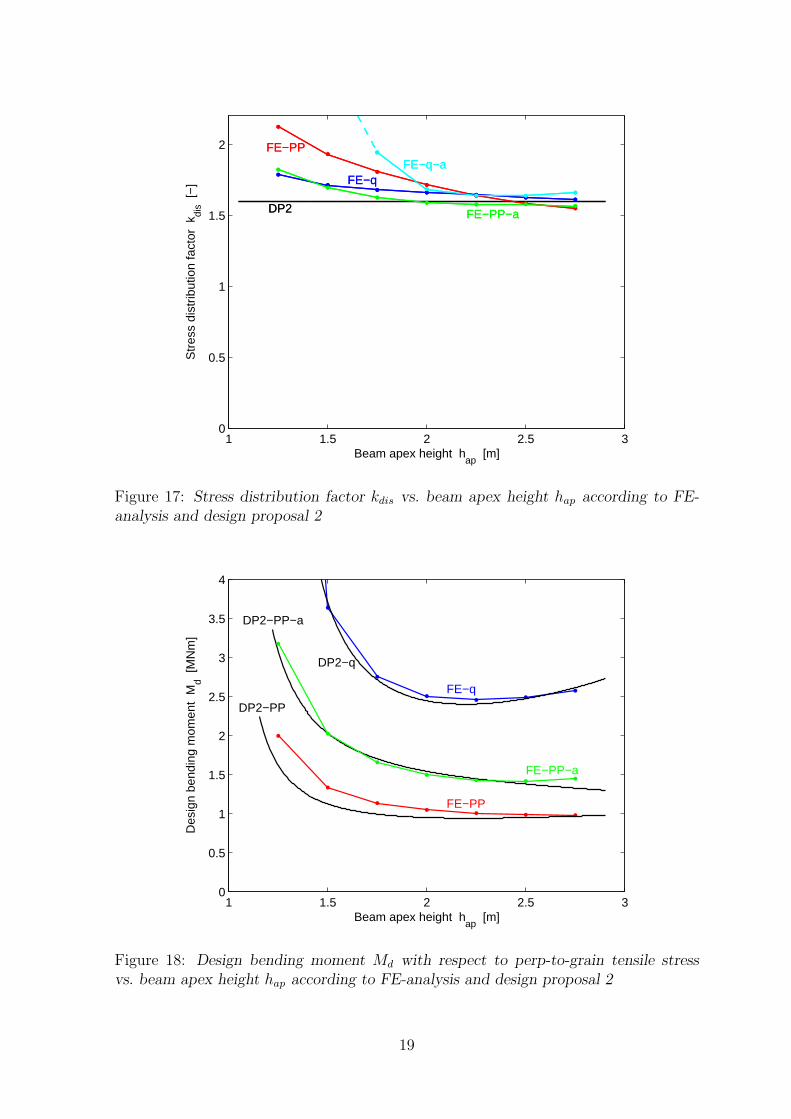
distribution factor kdis and design bending moment Md with respect to perp-to-graintensile stress is presented in Figures 15-18 for FE-analysis and design proposal 2 (DP2).
17

1 1.5 2 2.5 30
0.02
0.04
0.06
0.08
0.1
0.12
0.14
0.16
0.18
0.2
DP2−PP−a
DP2−q−a
DP2−q
DP2−PP
FE−PP
FE−PP−a
FE−q
FE−q−a
Beam apex height hap
[m]
Max
imum
per
p−to
−gr
ain
tens
ile s
tres
s σ
t90 [
MP
a]
Figure 15: Maximum perp-to-grain tensile stress vs. beam apex height hap according toFE-analysis and design proposal 2 for applied loads corresponding to M = 1000 kNm
1 1.5 2 2.5 30
0.1
0.2
0.3
0.4
0.5
0.6
0.7
FE−q
FE−PP
FE−PP−a
FE−q−aDP2−q
DP2−PP
Beam apex height hap
[m]
Str
esse
d vo
lum
e fa
ctor
kvo
l [−
]
Figure 16: Stressed volume factor kvol vs. beam apex height hap according to FE-analysis and design proposal 2
18
1 1.5 2 2.5 30
0.5
1
1.5
2 FE−PP
FE−PP−a
FE−qFE−q−a
DP2
Beam apex height hap
[m]
Str
ess
dist
ribut
ion
fact
or k
dis [
−]
FE−PP
FE−PP−a
FE−qFE−q−a
DP2
Figure 17: Stress distribution factor kdis vs. beam apex height hap according to FE-analysis and design proposal 2
1 1.5 2 2.5 30
0.5
1
1.5
2
2.5
3
3.5
4
FE−PP
FE−PP−a
FE−q
DP2−PP
DP2−q
DP2−PP−a
Beam apex height hap
[m]
Des
ign
bend
ing
mom
ent
Md [
MN
m]
Figure 18: Design bending moment Md with respect to perp-to-grain tensile stressvs. beam apex height hap according to FE-analysis and design proposal 2
19
7 Concluding remarks
A brief review of design criteria and finite element stress analysis, focusing on the perp-to-grain tensile stress, of double-tapered glulam beams are presented. The review ofthe Eurocode 5 design criteria reveals that the introduction of a reduced effective beamwidth (due to presence of cracks) for design with respect to shear stress has a majorinfluence on the overall design strength of double-tapered beams. Disregarding designwith respect to shear stress, the review further shows that perp-to-grain tensile stressat apex region may be decisive for design for double-tapered beams except for beamswith small inclination. Design with respect to perp-to-grain tensile stress is based onan approximate solution for the magnitude of stress and Weibull type considerationsrelating to influence of size of stressed volume and level of heterogeneity in stressdistribution on the strength.
Linear elastic finite element stress analysis of regular double tapered beams anddouble-tapered beams with a flattened apex region are presented. The FE-analysisconcerns magnitude of stress, size of stressed volume and level of heterogeneity in stressdistribution. For beam geometries with a flattened apex region, the maximum perp-to-grain tensile stress was found to be reduced significantly compared to the stressin corresponding regular double-tapered beams. The FE-analysis further revealed aconsiderable difference in not only the maximum stress but also in the size of thestressed volume between different load configuration, here uniformly distributed loadand two point loads acting at the beam length quarter points.
In Eurocode 5, a reduction of design stress is allowed for load configurations withuniformly distributed load but the difference in size of the stressed volume, whichaffect the design strength, is however not accounted for. The size of the stressedvolume found from FE-analysis is further greater than assumed in Eurocode 5 for allconsidered geometries. Although underestimating the size of the stressed volume, theoverall design strength with respect to perp-to-grain tensile stress based on Eurocode5 seems to correspond rather well with FE-analysis and Weibull theory. This is due tounderestimation of the level of heterogeneity in stress distribution in Eurocode 5.
Two proposals for design criterion with respect to perp-to-grain tensile stress arepresented. They are both based on the Eurocode 5 approach for regular double-taperedbeams and consists of modifications of the approximate expression for determining themaximum stress, size of stressed volume and level of heterogeneity in stress distribution.All modifications are introduced solely based on the results of the FE-analysis and arein not way adjusted to experimental test results.
20

References
[1] Carling O.LimtrahandbokSvenskt Limtra AB, Print & Media Center i Sundsvall AB, 2001
[2] Danielsson H.The strength of glulam beams with holes -A probabilistic fracture mechanics method and experimental testsReport TVSM-3069, Division of Structural Mechanics, Lund Univeristy, 2009
[3] Emilsson A.Limtrateknik ABPersonal communication, 2009
[4] Foschi R., Fox S.Radial stresses in curved timber beamsJournal of the Structural Division, Proceedings of the American Society of Civil Engineering,vol. 96, no st10, pp 1997-2008, 1970
[5] Larsen H.J., Riberholt H.Traekonstuktioner - BeregningSBI-Anvisning 193, 5. Udgave, Statens Byggeforskningsinstitut, 2000
[6] Riberholt H.Tapered timber beamsCIB-W18/11-10-1, Vienna, Austria, 1979
[7] SS-EN 1995-1-1:2004Eurocode 5: Design of timber structures - Part 1-1:General - Common rules and rules for buildings
[8] SS-EN 1194:1999Glued laminated timber - Strength classes and determination of characteristic values
[9] Thelandersson S., Larsen H.J.Timber EngineeringJohn Wiley & Sons Ltd, Chichester, England, 2003
[10] Weibull W.A Statistical theory of the strength of materialsProceedings nr 151, The Royal Swedish Institute of Engineering Research, Stockholm, 1939
21