design and performance analysis of single inlet … · keywords: thrust vector, multiple nozzle,...
TRANSCRIPT

Design and Performance Analysis of Single
Inlet Multiple
Outlet (SIMO) Nozzle with Thrust Vector
Control
Kalidass R
1, Balaji S
2,
1
Post Graduate Scholar, Department of Aeronautical Engineering,
2
Assistant Professor, Department of Aeronautical Engineering,
Nehru Institute of Engineering and Technology, T.M. Palayam, Coimbatore – 641 105,
Tamil Nadu, India.
Abstract--
Today, thrust vectoring has become a very
important research subject which can dramatically change the
way aircraft manoeuvring in the future and their performance.
This paper a concept defined as SIMO (Single Inlet Multiple
Outlet) in detail. This can be explained by having multiple
nozzles for exhaust purpose than those conventional one or two
nozzles as we know of presently. This idea may yet not be able
to apply directly to VTOL (Vertical Take off& Landing), but
can be applied very well to change thrust direction of the
aircraft effectively including thrust reversal and hence
reducing the dependability on the primary control surface to
great extent.
Keywords: thrust vector, multiple nozzle, thrust reversal,
directional control
I.
INTRODUCTION A nozzle
is a device designed to control the
direction or characteristics of a fluid flow (especially to
increase velocity).
A nozzle is often a pipe or tube of varying cross
sectional area, and it can be used to direct or modify the
flow of a fluid (liquid or gas). Nozzles are frequently used
to control the rate of flow, speed, direction, mass, shape,
and/or the pressure of the stream that emerges from them
nozzles can be described as
a)
Convergent Nozzle
b)
Divergent Nozzle
c)
ConvergentDivergent Nozzle
A.
CONVERGENT NOZZLE The nozzle in which narrowing down from a wide diameter
to a smaller diameter in the direction of the flow.
Convergent nozzles accelerate subsonic fluids. If the nozzle
pressure ratio is high enough the flow will reach sonic
velocity at the narrowest point (i.e. the nozzle throat). In this
situation, the nozzle is said to be choked.
B.
DIVERGENT NOZZLE Expanding from a smaller diameter to a larger one.
Divergent nozzles slow fluids, if the flow is subsonic, but
accelerate sonic or supersonic fluids.
C.
CONVERGENT DIVERGENT NOZZLE
Convergent divergent nozzle can therefore accelerate fluids
that have choked in the convergent section to supersonic
speeds. This CD process is more efficient than allowing a
convergent nozzle to expand supersonically externally. The
shape of the divergent section also ensures that the direction
of the escaping gases is directly backwards, as any sideways
component would not contribute to thrust.
II.
SINGLE INLET MULTIPLE OUTLET Here the project presents a concept about SIMO
(Single Inlet Multiple Outlet) Nozzle. Normally in present
day aircrafts currently employ one nozzle per engine here
the SIMO employs five nozzles instead of one nozzle to
single engine. Where the four of these five nozzles are
equipped with thrust vectoring, so we can achieve all
directional control of the aircraft thus reducing our
dependence on the control surfaces.
2939
Vol. 3 Issue 2, February - 2014
International Journal of Engineering Research & Technology (IJERT)
IJERT
IJERT
ISSN: 2278-0181
www.ijert.orgIJERTV3IS20160
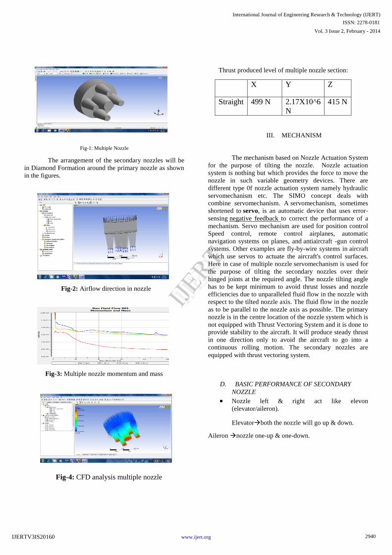
Fig-1: Multiple Nozzle
The arrangement of the secondary nozzles will be
in Diamond Formation around the primary nozzle as shown
in the figures.
Fig-2: Airflow direction in nozzle
Fig-3:
Multiple nozzle momentum and mass
Fig-4: CFD analysis multiple nozzle
Thrust produced level of multiple nozzle section:
X
Y
Z
Straight
499 N
2.17X10^6
N
415 N
III.
MECHANISM
The mechanism based on Nozzle Actuation System
for the purpose of tilting the nozzle. Nozzle actuation
system is nothing but which provides the force to move the
nozzle in such variable geometry devices. There are
different type 0f nozzle actuation system namely hydraulic
servomechanism etc. The SIMO concept deals with
combine servomechanism. A servomechanism, sometimes
shortened to servo, is an automatic device that uses error-
sensing negative feedback to correct the performance of a
mechanism. Servo mechanism are used for position control
Speed control, remote control airplanes, automatic
navigation systems on planes, and antiaircraft -gun control
systems. Other examples are fly-by-wire systems in
aircraft
which use servos to actuate the aircraft's control surfaces.
Here in case of multiple nozzle servomechanism is used for
the purpose of tilting the secondary nozzles over their
hinged joints at the required angle. The nozzle tilting angle
has to be kept minimum to avoid thrust losses and nozzle
efficiencies due to unparalleled fluid flow in the nozzle with
respect to the tilted nozzle axis. The fluid flow in the nozzle
as to be parallel to the nozzle axis as possible. The primary
nozzle is in the centre location of the nozzle system which is
not equipped with Thrust Vectoring System and it is done to
provide stability to the aircraft. It will produce steady thrust
in one direction only to avoid the aircraft to go into a
continuous rolling motion. The secondary nozzles are
equipped with thrust vectoring system.
D.
BASIC PERFORMANCE OF SECONDARY
NOZZLE
Nozzle left & right act like elevon
(elevator/aileron).
Elevatorboth the nozzle will go up & down.
Aileron nozzle one-up & one-down.
2940
Vol. 3 Issue 2, February - 2014
International Journal of Engineering Research & Technology (IJERT)
IJERT
IJERT
ISSN: 2278-0181
www.ijert.orgIJERTV3IS20160

Fig-5:
Nozzle move condition
Nozzle up & down act like rudder
Rudder
nozzle left & right
IV.
BOUNDRY CONDITION INLET:
E.
Pitch down Condition
Total pressure: 22atm
Temperature: 2000k
Outlet: subsonic
Fig-6: Pitch down condition nozzle
Fig-7: CFD analysis of Pitch down nozzle
Fig-8:Momentum and mass
flow rate of pitch down nozzle
F.
Roll left Condition
Total pressure: 22atm
Temperature: 2000k
Outlet: subsonic
Fig-9: Roll left condition nozzle
Fig-10: CFD analysis of Roll left
nozzle
2941
Vol. 3 Issue 2, February - 2014
International Journal of Engineering Research & Technology (IJERT)
IJERT
IJERT
ISSN: 2278-0181
www.ijert.orgIJERTV3IS20160

Fig-11: Thrust exhaust view of ansys
Fig-12:Momentum and mass flow rate of roll leftnozzle
Fig-13: Roll right condition nozzle
Fig-14: CFD analysis of Roll right nozzle
G. Roll right Condition
Total pressure: 22atm
Temperature: 2000k
Outlet: subsonic
Fig-15: Momentum and mass flow rate of roll right
nozzle
H. Yaw left Condition
Total pressure: 22atm
Temperature: 2000k
Outlet: subsonic
Fig-16: Yaw left condition nozzle
2942
Vol. 3 Issue 2, February - 2014
International Journal of Engineering Research & Technology (IJERT)
IJERT
IJERT
ISSN: 2278-0181
www.ijert.orgIJERTV3IS20160

Fig-17: CFD analysis of yaw left nozzle
Fig-18: Thrust produced level of yaw left nozzle
Fig-19: Momentum and mass flow rate of yaw left
nozzle
I. Yaw right Condition
Total pressure: 22atm
Temperature: 2000k
Outlet: subsonic
Fig-20: Yaw right condition nozzle
Fig-21: Thrust produced level of yaw right nozzle
Fig-22: Momentum and mass flow rate of yaw right
nozzle
2943
Vol. 3 Issue 2, February - 2014
International Journal of Engineering Research & Technology (IJERT)
IJERT
IJERT
ISSN: 2278-0181
www.ijert.orgIJERTV3IS20160

RESULT
Thrust produced level of nozzle section:
X Y Z
STRAIGHT 499 N -2.17X10^6 N
415 N
PITCH UP 73 N -2.17X10^6 N
63873 N
PITCH DOWN
73 N -2.17X10^6 N
-63873 N
ROLL LEFT
-128 N -2.17X10^6 N
270.96 N
ROLL RIGHT
128 N -2.17X10^6 N
-270.96 N
YAW RIGHT
63735.7 N
-2.17X10^6 N
352.89 N
YAW LEFT
-63735.7 N
-2.17X10^6 N
-352.8 N
CONCLUSIONS
With thrust reversal system installed on all the
nozzles we can achieve thrust reversal too giving the
aircraft unprecedented manoeuvrability and ease of
slowing down the aircraft during landing. With these
kind of nozzles very high degree of manoeuvrability
can be achieved. In defence aircraft, these
manoeuvres can give very high precision of
targeting in air dogfights. These nozzles when
installed with conventional thrust reversal systems,
they can keep the aircraft in air at a very low speed
and may also help in reducing the stall velocity
which can hence lead to safer landings. These can
also be applied to space propulsion particularly as it
can control the direction of spacecraft in space
which is normally difficult to control. These nozzles
can be made to work in tandem with primary control
surfaces so that someday in future in case of failure
of primary control surfaces occur, the aircraft can
still be maneuverer and saved thereby avoiding loss
of millions of dollars’ worth of property, aircraft and
most important pilot’s life.
REFERENCES
[1] STOL Aircraft Design for Undergraduates, Russell M
Cummings, David W Hall; dept. of Aerospace
Engineering, California Polytechnic State University,
California, USA as in AIAA 2002-5998
[2] Reconfigurable flight control, M Pachter and E B
Nelson; dept. of Electrical and Computer Engineering, Air
Force Institute of Technology, Wright Patterson AFB,
USA
[3] The JSF STOVL Performance Process- from small scale
Database to flight test demonstration, Kevin M
McCarthy; JSF Program Office/Naval Air Systems
Command, USA as in AIAA 2002-6002
[4] Early 21st Century Executive VTOL Aircraft, William F
Chana; Design Consultant, San Diego, California, USA as
in AIAA 2002-5996
[6] Highlights of the JSF X-35 STOVL Jet Effects Test
Effort, Mark D Buchholz; Lockheed Martin Aeronautics
Company, California, USA as in AIAA 2002-5962
2944
Vol. 3 Issue 2, February - 2014
International Journal of Engineering Research & Technology (IJERT)
IJERT
IJERT
ISSN: 2278-0181
www.ijert.orgIJERTV3IS20160
