design and installation manual for infiltrator...
TRANSCRIPT

JULY 2015
Design and Installation Manual for Infiltrator Chambers in North Carolina
The purpose of this product information sheet is to provide specific design and installation information pertinent for the use of Infiltrator Quick4 Plus chambers in North Carolina.
For more detailed design information, please contact Infiltrator Water Technologies at 1-800-221-4436
North Carolina
Infiltrator Chambers in North CarolinaINTRODUCTION 2
STATE APPROVAL SUMMARY 4
PRODUCTS 5
SYSTEM SIZING 7
CHAMBER CONFIGURATIONS 11
INSTALLATION INSTRUCTIONS 20
INSPECTORS CHECKLIST 26
WARRANTY 27
North Carolina
www.infiltratorwater.com
North Carolina
New Hanover
Brunswick
Columbus
Pender
BladenRobeson
Onslow
Scotland
Carteret
Craven
Clay
Richmond
Duplin
Union
Hoke
Anson
Jones
Cumberland
Cherokee
Sampson
PamlicoMacon
Polk
Craven
Gaston
Transylvania
LenoirGraham
Henderson Stanly
Cabarrus
Montgomery Moore
Mecklenburg
JacksonBeaufort
Lincoln
Cleveland
Harnett
WayneRutherford Lee
GreeneSwain
HydeBeaufortHaywood
Johnston
Buncombe
Catawba
Pitt
Rowan
Wilson
ChathamRandolphMcDowell DareWashingtonTyrrell
Burke
Davidson
AlexanderIredell Davie
Madison
Martin
Wake
Yancey
Caldwell
Edgecombe
MitchellNash
Durham
Orange
Bertie
Alamance
Guilford
Forsyth
FranklinAvery
Yadkin Chowan
PerquimansWataugaWilkes
PasquotankHalifaxCaswellRockingham
GranvilleVancePerson
Hertford
NorthamptonWarren
CamdenStokes
CurrituckGates
Surry
AlleghanyAshe
Raleigh

Contact Infiltrator Water Technologies 1-800-221-4436 for additional technical and product information.2
INTRODUCTION
Quick4 ChambersQuick4 High Capacity, Quick4 Plus Standard, Quick4 Standard and Quick4 Plus Standard Low Profile (LP) chambers fit into a 36-inch-wide trench. The Quick4 Plus Standard LP chamber is 4 inches shorter than the other standard chamber model, allowing for shallower installation. The Quick4 Plus line of endcaps is available with these chambers, providing increased flexibility in system configurations. All chambers can be installed in a conventional bed system (15A NCAC 18A.1955). Ask your local Infiltrator sales representative for specific information on various system-inletting options.
QUICK4 PLUS STANDARDQuick4 Plus Standard Nominal Chamber SpecificationsSize: 34”W x 48”L x 12”H
Storage Capacity: 45 gal
Invert Elevation: 5.3”, 8”
Equivalency Rating/Sizing 4.0 ft2/lfMinimum Trench Spacing: 9-ft on center
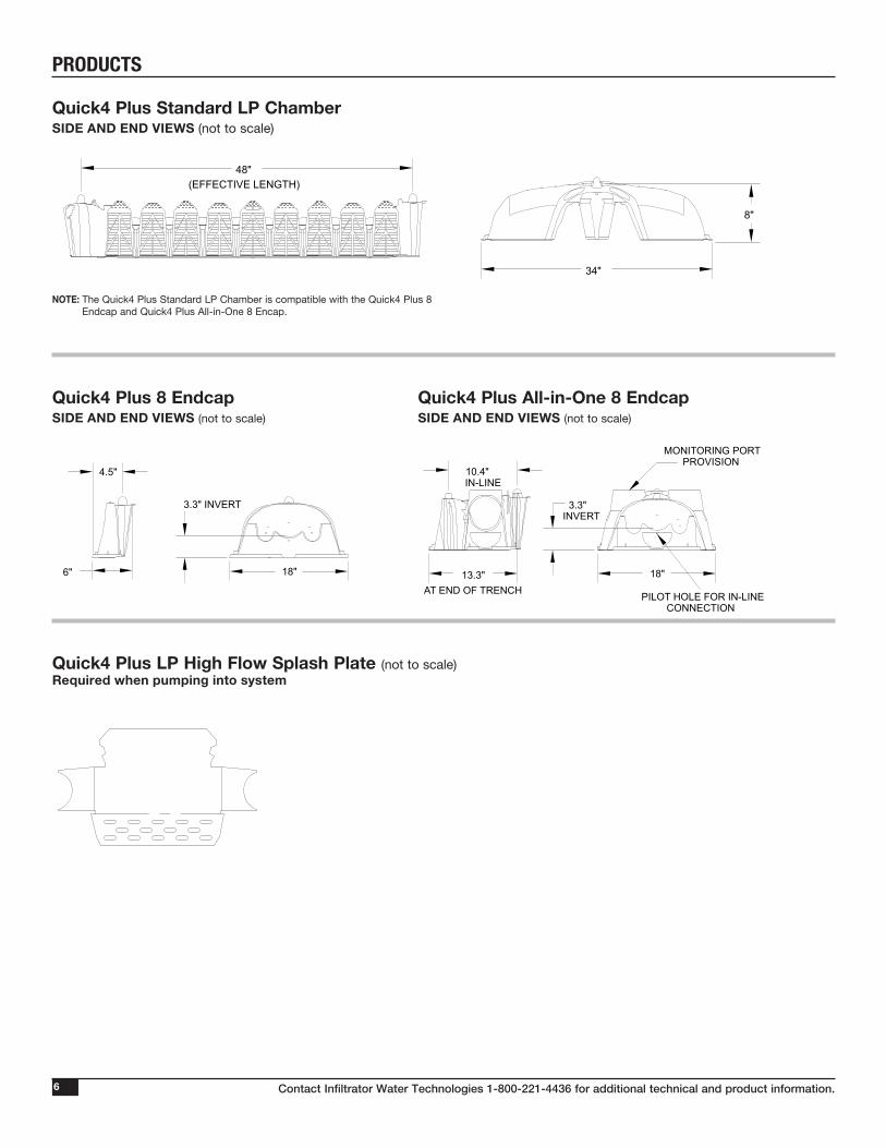
QUICK4 PLUS STANDARD LOW PROFILE (LP)
Quick4 Plus Standard Low Profile (LP) Nominal Chamber SpecificationsSize: 34”W x 48”L x 8”H
Storage Capacity: 32 gal
Invert Elevation: 3.3”, 9”
Equivalency Rating/Sizing 3.0 ft2/lf
Minimum Trench Spacing: 9-ft on center
QUICK4 EQUALIZER 24
Quick4 Equalizer 24 Chamber Nominal Specifications
Size 16”W x 53”L x 11”H
Storage Capacity 20.8 gal
Invert Elevation 6”
Equivalency Rating/Sizing 2.0 ft2/lf
Minimum Trench Spacing: 6-ft on center
Quick4 High Capacity Chamber Nominal SpecificationsSize 34”W x 48”L x 16”H
Storage Capacity 62 gal
Invert Elevation 11.5”
Equivalency Rating/Sizing 4.0 ft2/lf
Minimum Trench Spacing: 9-ft on center
QUICK4 HIGH CAPACITY

Contact Infiltrator Water Technologies 1-800-221-4436 for additional technical and product information. 3
INTRODUCTION
Infiltrator IM-Series Tanks
Tank
IM-1060
IM-1530
Applications Suitable for use as a pump tank, 2-compartment septic tank or rainwater
storage tank, shallow, multiple, and serial tank configurations.
Suitable for use as a pump tank, 2-compartment septic tank or rainwater
storage tank, shallow, multiple, and serial tank configurations.
Working Capacity 1,094 gal 1,537 gal
Total Capacity 1,287 gal 1,787 gal
Septic Tank Approval Number STB-2071 STB-3000
Pump Tank Approval Number PT-2077 PT-2096
QUICK4 EQUALIZER 36
Quick4 Equalizer 36 Chamber Nominal Specifications
Size 22”W x 53”L x 12”H
Storage Capacity 32 gal
Invert Elevation 6”
Equivalency Rating/Sizing 3.0 ft2/lf
Minimum Trench Spacing: 7-ft on center

Contact Infiltrator Water Technologies 1-800-221-4436 for additional technical and product information.4
STATE APPROVAL SUMMARY
Excerpt from AWWS 2005-01-R4. Accepted approval with 4.0 ft2/lf for the Quick4 Plus Standard chamber model and sizing only. Allows for substitution of any conventional permits.
CHAMBER APPROVAL SUMMARY
1. AWWS 2005-01-R42. IWWS-2010-1-R23. CDWS 2010-1-R2B
Model Accepted1 Innovative2 Controlled Demonstration3
Quick4 Plus Standard x x
Quick4 Plus Standard LP x x
Quick4 High Capacity x
Quick4 Equalizer 36 x
Quick4 Equalizer 24 x
IX. Responsibilities and Permitting
A. The local health department shall permit these accepted system in an equivalent manner as a convention-al system, when the requirements of 15A NCAC 18A .1900 et. Seq., laws, and conditions of this accepted system approval are met.
B. When use of one or more of these accepted systems is requested in the application for a Construction Authorization, the local health department shall include a design for the designated accepted system(s) in accordance with the approved siting, sizing, and design criteria on the Construction Authorization.
C. When a permit or authorization is issued for a conventional system, the permit or authorization shall con-tain a statement that indicates that an accepted system may also be used. These accepted systems may be installed without permit/authorization modification, prior approval of the health department, or separate sign-off, if the accepted system can be placed in the permitted/authorized trench footprint and the installa-tion is in accordance with the accepted system approval, without unauthorized product alteration.
D. When substitution with one of these accepted systems for a conventional system or another accepted system is made, permit modification, prior approval of the health department or separate owner sign-off is not required as long as no changes are necessary in the location of each nitrification line (except reduction in line length and/or number as allowed for in this approval), trench depth, or effluent distribution method.
E. Notwithstanding paragraphs C and D above, when a substitution in system type compared to a previously permitted or authorized system type or types shall result in a change in the location of any nitrification line (including any increase in line length), trench depth, or effluent distribution method, prior approval by the local health department is required before system installation. The local health department shall modify the permit/authorization upon a finding that all provisions of this approval and all other applicable rules shall be met.
F. The type of system installed shall be indicated on the Operation Permit, including designation of the man-ufacturer and model or unique code.

Contact Infiltrator Water Technologies 1-800-221-4436 for additional technical and product information. 5
PRODUCTS
Quick4 Plus Standard High Flow Splash PlateFLAT VIEW (not to scale)
Quick4 Plus Standard Chamber SIDE AND END VIEWS (not to scale)
Quick4 Plus All-in-One12 EndcapSIDE AND END VIEWS (not to scale)
NOTES:For use with the Quick4 Plus Standard Chambers.
(EFFECTIVE LENGTH)
MONITORING PORTPROVISION
IN-LINE
AT END OF TRENCHPILOT HOLE FOR IN-LINE
CONNECTION
48"
12"
34"
8" INVERT
33" 18.2"
11.2"
8" INVERT
5.25"INVERT
(EFFECTIVE LENGTH)
MONITORING PORTPROVISION
IN-LINE
AT END OF TRENCHPILOT HOLE FOR IN-LINE
CONNECTION
48"
12"
34"
8" INVERT
33" 18.2"
11.2"
8" INVERT
5.25"INVERT
Contact Infiltrator Water Technologies 1-800-221-4436 for additional technical and product information.6
PRODUCTS
Quick4 Plus LP High Flow Splash Plate (not to scale)Required when pumping into system
Quick4 Plus Standard LP ChamberSIDE AND END VIEWS (not to scale)
NOTE: The Quick4 Plus Standard LP Chamber is compatible with the Quick4 Plus 8 Endcap and Quick4 Plus All-in-One 8 Encap.
Quick4 Plus 8 EndcapSIDE AND END VIEWS (not to scale)
Quick4 Plus All-in-One 8 EndcapSIDE AND END VIEWS (not to scale)
TOP VIEW
SIDE VIEW END VIEW
16.54
15.7010.53
4.00
(EFFECTIVE LENGTH)
10.4"
QUICK4 PLUSALL-IN-ONE PERISCOPE
(360° SWIVEL )USE THE PERISCOPE FORA 9" INVERT WITH THEQUICK 4 PLUS STANDARDLOW PROFILE CHAMBER QUICK4 PLUS
ALL-IN-ONE 8ENDCAP
IN-LINE
AT END OF TRENCH
INVERT
MONITORING PORTPROVISION
PILOT HOLE FOR IN-LINECONNECTION
18"
4.5"
48"
34"
8"
18"13.3"6"
9"
3.3"3.3" INVERT
Contact Infiltrator Water Technologies 1-800-221-4436 for additional technical and product information. 7
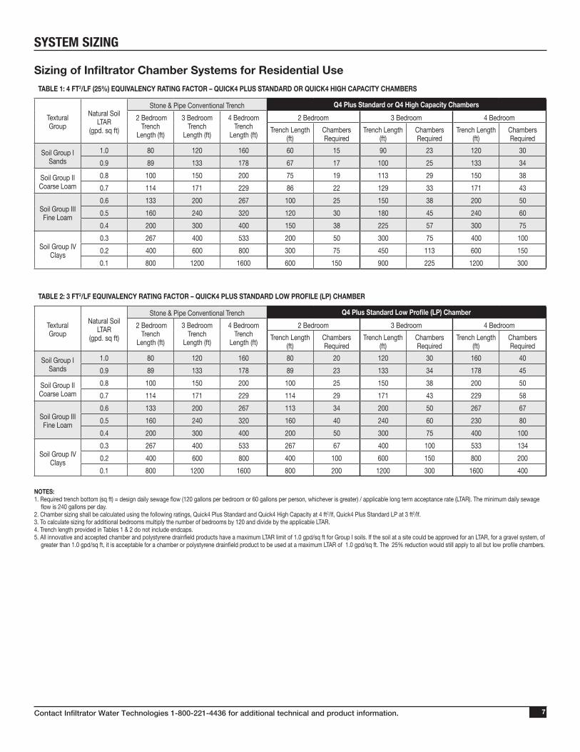
Sizing of Infiltrator Chamber Systems for Residential UseTABLE 1: 4 FT2/LF (25%) EQUIVALENCY RATING FACTOR – QUICK4 PLUS STANDARD OR QUICK4 HIGH CAPACITY CHAMBERS
Textural Group
Natural Soil LTAR
(gpd. sq ft)
Stone & Pipe Conventional Trench Q4 Plus Standard or Q4 High Capacity Chambers 2 Bedroom
TrenchLength (ft)
3 BedroomTrench
Length (ft)
4 BedroomTrench
Length (ft)
2 Bedroom 3 Bedroom 4 BedroomTrench Length
(ft)Chambers Required
Trench Length (ft)
Chambers Required
Trench Length (ft)
Chambers Required
Soil Group I Sands
1.0 80 120 160 60 15 90 23 120 300.9 89 133 178 67 17 100 25 133 34
Soil Group II Coarse Loam
0.8 100 150 200 75 19 113 29 150 380.7 114 171 229 86 22 129 33 171 43
Soil Group III Fine Loam
0.6 133 200 267 100 25 150 38 200 500.5 160 240 320 120 30 180 45 240 600.4 200 300 400 150 38 225 57 300 75
Soil Group IV Clays
0.3 267 400 533 200 50 300 75 400 1000.2 400 600 800 300 75 450 113 600 1500.1 800 1200 1600 600 150 900 225 1200 300
TABLE 2: 3 FT2/LF EQUIVALENCY RATING FACTOR – QUICK4 PLUS STANDARD LOW PROFILE (LP) CHAMBER
Textural Group
Natural Soil LTAR
(gpd. sq ft)
Stone & Pipe Conventional Trench Q4 Plus Standard Low Profile (LP) Chamber 2 Bedroom
TrenchLength (ft)
3 BedroomTrench
Length (ft)
4 BedroomTrench
Length (ft)
2 Bedroom 3 Bedroom 4 BedroomTrench Length
(ft)Chambers Required
Trench Length (ft)
Chambers Required
Trench Length (ft)
Chambers Required
Soil Group I Sands
1.0 80 120 160 80 20 120 30 160 400.9 89 133 178 89 23 133 34 178 45
Soil Group II Coarse Loam
0.8 100 150 200 100 25 150 38 200 500.7 114 171 229 114 29 171 43 229 58
Soil Group III Fine Loam
0.6 133 200 267 113 34 200 50 267 670.5 160 240 320 160 40 240 60 230 800.4 200 300 400 200 50 300 75 400 100
Soil Group IV Clays
0.3 267 400 533 267 67 400 100 533 1340.2 400 600 800 400 100 600 150 800 2000.1 800 1200 1600 800 200 1200 300 1600 400
SYSTEM SIZING
NOTES: 1. Required trench bottom (sq ft) = design daily sewage flow (120 gallons per bedroom or 60 gallons per person, whichever is greater) / applicable long term acceptance rate (LTAR). The minimum daily sewage
flow is 240 gallons per day.2. Chamber sizing shall be calculated using the following ratings, Quick4 Plus Standard and Quick4 High Capacity at 4 ft2/lf, Quick4 Plus Standard LP at 3 ft2/lf.3. To calculate sizing for additional bedrooms multiply the number of bedrooms by 120 and divide by the applicable LTAR.4. Trench length provided in Tables 1 & 2 do not include endcaps.5. All innovative and accepted chamber and polystyrene drainfield products have a maximum LTAR limit of 1.0 gpd/sq ft for Group I soils. If the soil at a site could be approved for an LTAR, for a gravel system, of
greater than 1.0 gpd/sq ft, it is acceptable for a chamber or polystyrene drainfield product to be used at a maximum LTAR of 1.0 gpd/sq ft. The 25% reduction would still apply to all but low profile chambers.
Contact Infiltrator Water Technologies 1-800-221-4436 for additional technical and product information.8
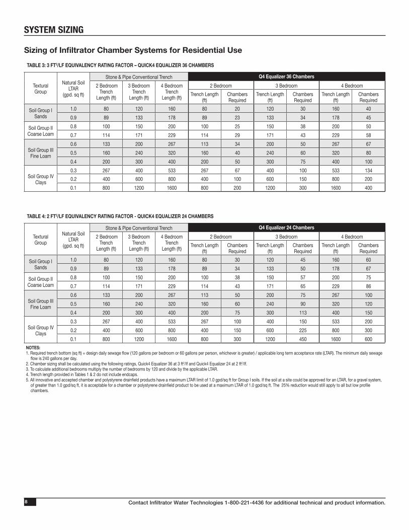
Sizing of Infiltrator Chamber Systems for Residential UseTABLE 3: 3 FT2/LF EQUIVALENCY RATING FACTOR – QUICK4 EQUALIZER 36 CHAMBERS
Textural Group
Natural Soil LTAR
(gpd. sq ft)
Stone & Pipe Conventional Trench Q4 Equalizer 36 Chambers 2 Bedroom
TrenchLength (ft)
3 BedroomTrench
Length (ft)
4 BedroomTrench
Length (ft)
2 Bedroom 3 Bedroom 4 BedroomTrench Length
(ft)Chambers Required
Trench Length (ft)
Chambers Required
Trench Length (ft)
Chambers Required
Soil Group I Sands
1.0 80 120 160 80 20 120 30 160 400.9 89 133 178 89 23 133 34 178 45
Soil Group II Coarse Loam
0.8 100 150 200 100 25 150 38 200 500.7 114 171 229 114 29 171 43 229 58
Soil Group III Fine Loam
0.6 133 200 267 113 34 200 50 267 670.5 160 240 320 160 40 240 60 320 800.4 200 300 400 200 50 300 75 400 100
Soil Group IV Clays
0.3 267 400 533 267 67 400 100 533 1340.2 400 600 800 400 100 600 150 800 2000.1 800 1200 1600 800 200 1200 300 1600 400
TABLE 4: 2 FT2/LF EQUIVALENCY RATING FACTOR - QUICK4 EQUALIZER 24 CHAMBERS
Textural Group
Natural Soil LTAR
(gpd. sq ft)
Stone & Pipe Conventional Trench Q4 Equalizer 24 Chambers 2 Bedroom
TrenchLength (ft)
3 BedroomTrench
Length (ft)
4 BedroomTrench
Length (ft)
2 Bedroom 3 Bedroom 4 BedroomTrench Length
(ft)Chambers Required
Trench Length (ft)
Chambers Required
Trench Length (ft)
Chambers Required
Soil Group I Sands
1.0 80 120 160 80 30 120 45 160 600.9 89 133 178 89 34 133 50 178 67
Soil Group II Coarse Loam
0.8 100 150 200 100 38 150 57 200 750.7 114 171 229 114 43 171 65 229 86
Soil Group III Fine Loam
0.6 133 200 267 113 50 200 75 267 1000.5 160 240 320 160 60 240 90 320 1200.4 200 300 400 200 75 300 113 400 150
Soil Group IV Clays
0.3 267 400 533 267 100 400 150 533 2000.2 400 600 800 400 150 600 225 800 3000.1 800 1200 1600 800 300 1200 450 1600 600
NOTES: 1. Required trench bottom (sq ft) = design daily sewage flow (120 gallons per bedroom or 60 gallons per person, whichever is greater) / applicable long term acceptance rate (LTAR). The minimum daily sewage
flow is 240 gallons per day.2. Chamber sizing shall be calculated using the following ratings, Quick4 Equalizer 36 at 3 ft2/lf and Quick4 Equalizer 24 at 2 ft2/lf.3. To calculate additional bedrooms multiply the number of bedrooms by 120 and divide by the applicable LTAR.4. Trench length provided in Tables 1 & 2 do not include endcaps.5. All innovative and accepted chamber and polystyrene drainfield products have a maximum LTAR limit of 1.0 gpd/sq ft for Group I soils. If the soil at a site could be approved for an LTAR, for a gravel system,
of greater than 1.0 gpd/sq ft, it is acceptable for a chamber or polystyrene drainfield product to be used at a maximum LTAR of 1.0 gpd/sq ft. The 25% reduction would still apply to all but low profile chambers.
SYSTEM SIZING

Contact Infiltrator Water Technologies 1-800-221-4436 for additional technical and product information. 9
SYSTEM SIZING
• Quick4 Plus Standard LP Chambers are sized at 1:1 with 3-foot-wide conventional gravel and pipe trenches and beds. • Chambers are approved for use under IWWS-2010-1-R2 for installation in 24 inches of naturally
occuring soil.• For use in 20 (soil group II - IV) to 26 (soil group I) inches of naturally occurring soil:
– The counties in Table 5 are approved under Innovative Wastewater System Approval, IWWS-290-1-R2.– All other counties are approved under Controlled Demonstration System Approval, CDWS-2010-1-R2B.
NOTES: 1. Soil profiles reffered to in this section are applicable to installations in soil groups II-IV. For installations in soil group I, please refer to the specified North Carolina approvals or contact Infiltrator.
Beaufort Duplin Pamlico
Bertie Edgecombe Pender
Bladen Gates Pasquotank
Brunswick Greene Perquimans
Camden Hertford Pitt
Carteret Hoke Robeson
Chowan Hyde Sampson
Columbus Jones Scotland
Craven Lenoir Tyrrell
Cumberland Martin Washington
Currituck New Hanover Wayne
Dare Onslow
TABLE 5: INNOVATIVE WASTEWATER SYSTEM APPROVAL – APPROVED COUNTIES
Quick4 Plus Standard LP Chamber
Trench Detail TYPICAL CROSS SECTION (not to scale)
12"
LIMITING LAYER CONDITIONS
36"
TOPSOIL
ESTABLISH VEGETATIVE COVER
NATIVE BACKFILL
Trench Depth 8"
6" Fill Depth

Contact Infiltrator Water Technologies 1-800-221-4436 for additional technical and product information.10
SYSTEM SIZING
Product Excavated Trench Width (inches)
Approved Chamber Equivalency Factor Linear
Foot Basis1 (ft2/lf)
Linear Feet of Chamber Credit per Pair When
Placed at Ends of Chamber Line (lf)2
Linear Feet of Chamber Credit per Unit when Placed as as
Mid-Line Connection (lf)3
Quick4 Plus Standard All-in-One 12 Endcap 36 4.0 2 1
Quick4 Plus Standard LP All-inOne 8 Endcap 36 3.0 1 1
Quick4 HC MultiPort Endcap 36 4.0 2 NA
Quick4 Equalizer 36 MultiPort Endcap 24 3.0 1 NA
Quick4 Equalizer 24 Multiport Endcap 18-24 2.0 1 NA
TABLE 6: Equivalency Factors for Quick4 Endcaps and Mid-Line Connections
NOTES: 1. Actual linear foot equivalency rating of compatible chamber part.2. Must install two (2) endcap parts to get approved linear feet of chamber credit.3. Single endcap part installed within chamber line receives one (1) linear foot of chamber credit.

Contact Infiltrator Water Technologies 1-800-221-4436 for additional technical and product information. 11
Parallel Distribution TYPICAL CROSS SECTION (not to scale)
TYPICAL PLAN VIEW (not to scale)
CHAMBER CONFIGURATIONS
NOTES: 1. See endcap sizing chart to determine endcap linear foot credit.2. Minimum 3” elevation drop required from d-box to endcap inlet invert.3. These are schematic drawings only; pipe size, type and layout per design.4. The Quick4 Plus Standard chamber is compatible with the Quick4 Plus All-in-One 12 Endcap. The Quick4 Plus Standard LP chamber is compatible with the Quick4 Plus All-in-One 8 Endcap and the Quick4
Plus 8 Endcap.
MOUND FOR PROPER DRAINAGE
TOPSOIL
ESTABLISH VEGETATIVE COVER
NATIVE BACKFILLGROUPS I, II, III, OR IV SOILS
34"
36"
QUICK4 PLUS STANDARD
6" MIN.(12" MIN. FOR H-10 LOAD RATING)
INFILTRATOR IM-SERIES SEPTIC TANK
D-BOX
LENGTH VARIES PER DESIGN
34"
9' MIN. ON CENTER
QUICK4 PLUS STANDARDQUICK4 PLUS
ENDCAPS (TYP.)
Contact Infiltrator Water Technologies 1-800-221-4436 for additional technical and product information.12
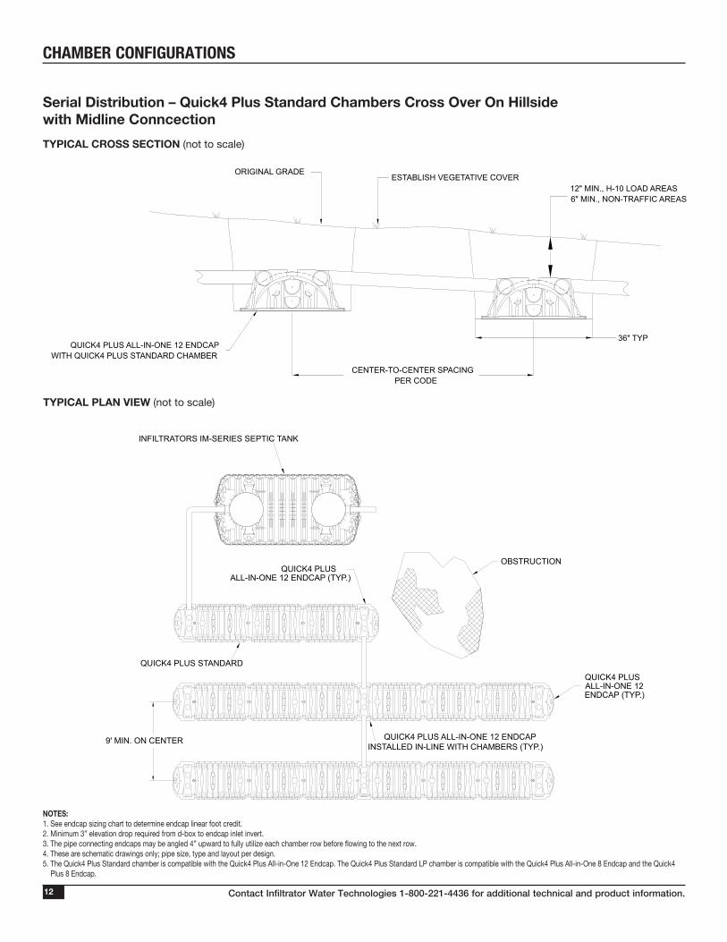
Serial Distribution – Quick4 Plus Standard Chambers Cross Over On Hillside with Midline ConncectionTYPICAL CROSS SECTION (not to scale)
TYPICAL PLAN VIEW (not to scale)
CHAMBER CONFIGURATIONS
ESTABLISH VEGETATIVE COVER
QUICK4 PLUS ALL-IN-ONE 12 ENDCAPWITH QUICK4 PLUS STANDARD CHAMBER
ORIGINAL GRADE
12" MIN., H-10 LOAD AREAS6" MIN., NON-TRAFFIC AREAS
CENTER-TO-CENTER SPACINGPER CODE
36" TYP
NOTES: 1. See endcap sizing chart to determine endcap linear foot credit.2. Minimum 3” elevation drop required from d-box to endcap inlet invert.3. The pipe connecting endcaps may be angled 4” upward to fully utilize each chamber row before flowing to the next row.4. These are schematic drawings only; pipe size, type and layout per design.5. The Quick4 Plus Standard chamber is compatible with the Quick4 Plus All-in-One 12 Endcap. The Quick4 Plus Standard LP chamber is compatible with the Quick4 Plus All-in-One 8 Endcap and the Quick4
Plus 8 Endcap.
9' MIN. ON CENTER
QUICK4 PLUS STANDARD
OBSTRUCTION
QUICK4 PLUSALL-IN-ONE 12ENDCAP (TYP.)
QUICK4 PLUSALL-IN-ONE 12 ENDCAP (TYP.)
QUICK4 PLUS ALL-IN-ONE 12 ENDCAPINSTALLED IN-LINE WITH CHAMBERS (TYP.)
INFILTRATORS IM-SERIES SEPTIC TANK

Contact Infiltrator Water Technologies 1-800-221-4436 for additional technical and product information. 13
Serial Distribution – Quick4 Plus Standard LP Chambers Using Alternating Ends TYPICAL CROSS SECTION (not to scale)
TYPICAL PLAN VIEW (not to scale)
CHAMBER CONFIGURATIONS
NOTES: 1. See endcap sizing chart to determine endcap linear foot credit.2. Minimum 3” elevation drop required from d-box to endcap inlet invert.3. The pipe connecting endcaps may be angled 4” upward to fully utilize each chamber row before flowing to the next row.4. These are schematic drawings only; pipe size, type and layout per design.5. The Quick4 Plus Standard chamber is compatible with the Quick4 Plus All-in-One 12 Endcap. The Quick4 Plus Standard LP chamber is compatible with the Quick4 Plus All-in-One 8 Endcap and the Quick4
Plus 8 Endcap.
ESTABLISH VEGETATIVE COVER
SUPPLY LINE FROM TANK
LINE TONEXT TRENCH
SAME-ENDHIGH-LEVEL OVERFLOW
ORIGINAL GRADE
90° ELBOW OR FITTINGSAS NECESSARY
9' MIN. ON CENTER
QUICK4 PLUS STANDARD LOW PROFILE CHAMBER
INFILTRATOR IM-SERIES SEPTIC TANK
QUICK4 PLUS ALL-IN-ONE 8 ENDCAP (TYP.)

Contact Infiltrator Water Technologies 1-800-221-4436 for additional technical and product information.14
Serial Distribution – Quick4 Plus Standard Chambers Using Quick4 Plus All-in-One 12 EndCaps as Drop Boxes TYPICAL CROSS SECTION (not to scale)
TYPICAL PLAN VIEW (not to scale)
CHAMBER CONFIGURATIONS
ESTABLISH VEGETATIVE COVER
SUPPLY LINE FROM TANK
LINE TONEXT TRENCH
SAME-ENDHIGH-LEVEL OVERFLOW
ORIGINAL GRADE
NOTES: 1. See endcap sizing chart to determine endcap linear foot credit.2. Minimum 3” elevation drop required from d-box to endcap inlet invert.3. The pipe connecting endcaps may be angled 4” upward to fully utilize each chamber row before flowing to the next row.4. These are schematic drawings only; pipe size, type and layout per design.5. The Quick4 Plus Standard chamber is compatible with the Quick4 Plus All-in-One 12 Endcap. The Quick4 Plus Standard LP chamber is compatible with the Quick4 Plus All-in-One 8 Endcap and the Quick4
Plus 8 Endcap.
9' MIN. ON CENTER
QUICK4 PLUS STANDARD CHAMBER
INFILTRATOR IM-SERIES SEPTIC TANK
QUICK4 PLUS ALL-IN-ONE 12 ENDCAP (TYP.)
Contact Infiltrator Water Technologies 1-800-221-4436 for additional technical and product information. 15
CHAMBER CONFIGURATIONS
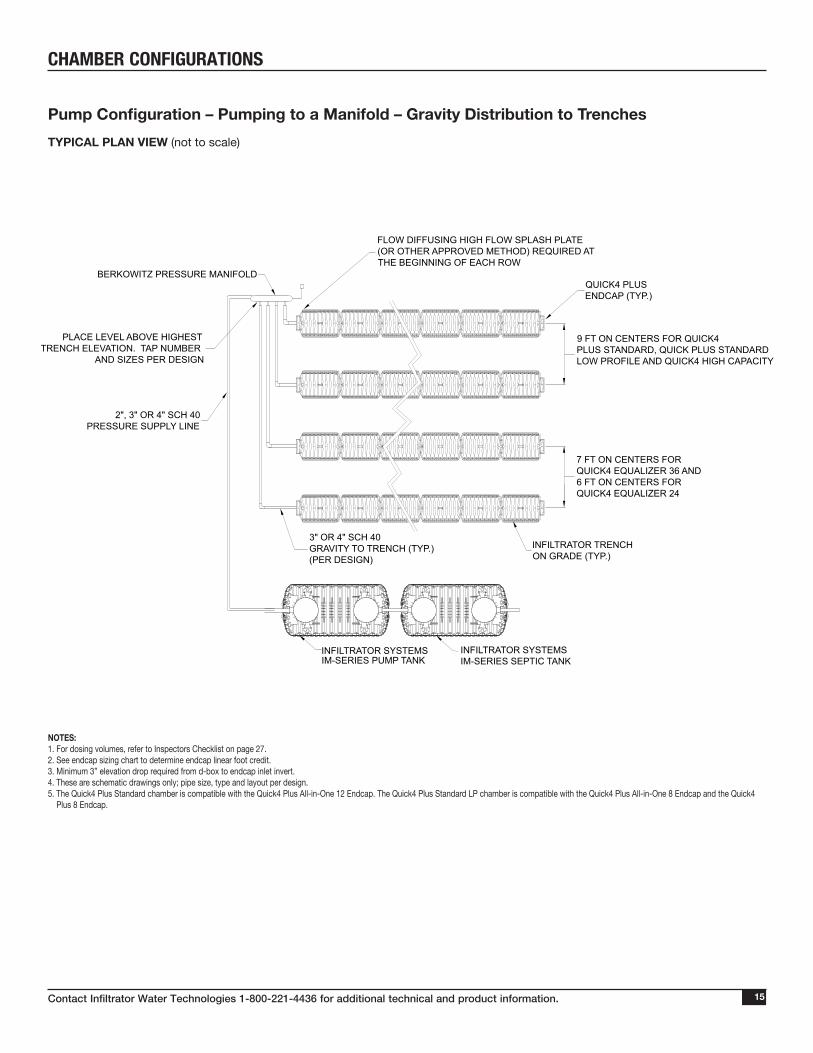
Pump Configuration – Pumping to a Manifold – Gravity Distribution to TrenchesTYPICAL PLAN VIEW (not to scale)
NOTES: 1. For dosing volumes, refer to Inspectors Checklist on page 27. 2. See endcap sizing chart to determine endcap linear foot credit.3. Minimum 3” elevation drop required from d-box to endcap inlet invert. 4. These are schematic drawings only; pipe size, type and layout per design.5. The Quick4 Plus Standard chamber is compatible with the Quick4 Plus All-in-One 12 Endcap. The Quick4 Plus Standard LP chamber is compatible with the Quick4 Plus All-in-One 8 Endcap and the Quick4
Plus 8 Endcap.
INFILTRATOR TRENCHON GRADE (TYP.)
7 FT ON CENTERS FORQUICK4 EQUALIZER 36 AND6 FT ON CENTERS FORQUICK4 EQUALIZER 24
9 FT ON CENTERS FOR QUICK4 PLUS STANDARD, QUICK PLUS STANDARD LOW PROFILE AND QUICK4 HIGH CAPACITY
3" OR 4" SCH 40GRAVITY TO TRENCH (TYP.)(PER DESIGN)
FLOW DIFFUSING HIGH FLOW SPLASH PLATE (OR OTHER APPROVED METHOD) REQUIRED AT THE BEGINNING OF EACH ROW
BERKOWITZ PRESSURE MANIFOLD
PLACE LEVEL ABOVE HIGHEST TRENCH ELEVATION. TAP NUMBER
AND SIZES PER DESIGN
2", 3" OR 4" SCH 40 PRESSURE SUPPLY LINE
QUICK4 PLUSENDCAP (TYP.)
INFILTRATOR SYSTEMSIM-SERIES SEPTIC TANK
INFILTRATOR SYSTEMS IM-SERIES PUMP TANK
Contact Infiltrator Water Technologies 1-800-221-4436 for additional technical and product information.16
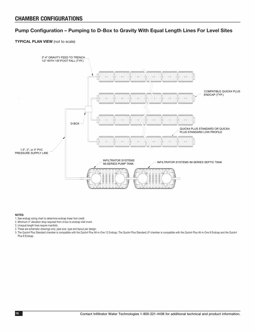
CHAMBER CONFIGURATIONS
Pump Configuration – Pumping to D-Box to Gravity With Equal Length Lines For Level Sites TYPICAL PLAN VIEW (not to scale)
NOTES: 1. See endcap sizing chart to determine endcap linear foot credit.2. Minimum 3” elevation drop required from d-box to endcap inlet invert. 3. Unequal length lines require manifold.2. These are schematic drawings only; pipe size, type and layout per design.3. The Quick4 Plus Standard chamber is compatible with the Quick4 Plus All-in-One 12 Endcap. The Quick4 Plus Standard LP chamber is compatible with the Quick4 Plus All-in-One 8 Endcap and the Quick4
Plus 8 Endcap.
1.5", 2", or 3" PVC PRESSURE SUPPLY LINE
D-BOX
3"-4" GRAVITY FEED TO TRENCH1/2” WITH 1/8”/FOOT FALL (TYP.)
INFILTRATOR SYSTEMS IM-SERIES SEPTIC TANK
COMPATIBLE QUICK4 PLUSENDCAP (TYP.)
QUICK4 PLUS STANDARD OR QUICK4 PLUS STANDARD LOW PROFILE
INFILTRATOR SYSTEMS IM-SERIES PUMP TANK
Contact Infiltrator Water Technologies 1-800-221-4436 for additional technical and product information. 17
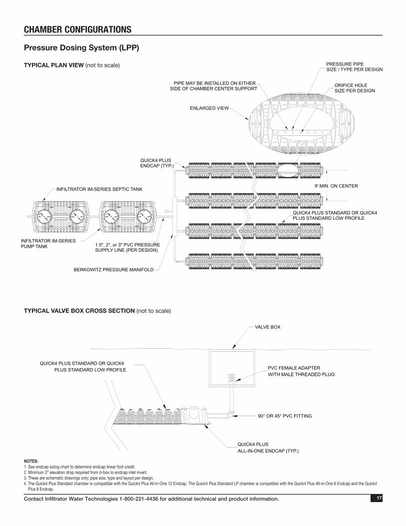
CHAMBER CONFIGURATIONS
TYPICAL VALVE BOX CROSS SECTION (not to scale)
Pressure Dosing System (LPP) TYPICAL PLAN VIEW (not to scale)
1.5", 2", or 3" PVC PRESSURE SUPPLY LINE (PER DESIGN)
BERKOWITZ PRESSURE MANIFOLD
PRESSURE PIPE SIZE / TYPE PER DESIGN
INFILTRATOR IM-SERIES SEPTIC TANK
ORIFICE HOLESIZE PER DESIGN
ENLARGED VIEW
QUICK4 PLUSENDCAP (TYP.)
QUICK4 PLUS STANDARD OR QUICK4 PLUS STANDARD LOW PROFILE
INFILTRATOR IM-SERIESPUMP TANK
PIPE MAY BE INSTALLED ON EITHER SIDE OF CHAMBER CENTER SUPPORT
9' MIN. ON CENTER
QUICK4 PLUS STANDARD OR QUICK4 PLUS STANDARD LOW PROFILE
QUICK4 PLUS ALL-IN-ONE ENDCAP (TYP.)
90° OR 45° PVC FITTING
PVC FEMALE ADAPTERWITH MALE THREADED PLUG
VALVE BOX
NOTES: 1. See endcap sizing chart to determine endcap linear foot credit.2. Minimum 3” elevation drop required from d-box to endcap inlet invert. 3. These are schematic drawings only; pipe size, type and layout per design.4. The Quick4 Plus Standard chamber is compatible with the Quick4 Plus All-in-One 12 Endcap. The Quick4 Plus Standard LP chamber is compatible with the Quick4 Plus All-in-One 8 Endcap and the Quick4
Plus 8 Endcap.

Contact Infiltrator Water Technologies 1-800-221-4436 for additional technical and product information.18
CHAMBER CONFIGURATIONS
Pressure Dosing System TYPICAL PLASTIC PIPE STRAP OPTION CROSS SECTION (not to scale)
Fill (Sand Mound) System TYPICAL CROSS SECTION (not to scale)
MIN. COVERPER CODE
8" OR 12"
PREPARE SUBGRADE PER DESIGN
NATIVE SOIL
ESTABLISH VEGETATIVE COVER
6 INCHES TOPSOIL (TYP.)
FILL MATERIAL PERSPEC. OR ASTM C-33
QUICK4 PLUS STANDARD OR QUICK4 PLUS STANDARD LOW PROFILE
3 (TYP.)1
DEPTH PER DESIGN 34"
NOTES: 1. See endcap sizing chart to determine endcap linear foot credit.2. Minimum 3” elevation drop required from d-box to endcap inlet invert. 3. The use of the Quick4 Plus Standrard LP will reduce your mound height by 4”.4. These are schematic drawings only; pipe size, type and layout per design.5. The Quick4 Plus Standard chamber is compatible with the Quick4 Plus All-in-One 12 Endcap. The Quick4 Plus Standard LP chamber is compatible with the Quick4 Plus All-in-One 8 Endcap and the Quick4
Plus 8 Endcap.
NOTE: All Quick4 Plus chamber models may be pressure-dosed in this manner.
ALL WEATHER PLASTICPIPE STRAP WITH 120 POUNDSTENSILE STRENGTH AT EVERY CHAMBER CONNECTION (TYP.)
PRESSURE PIPE WITH HOLES AT 12 O'CLOCK (TYP.), WITH FIRST, MIDDLE AND LAST ORIFICES AT 6 O’CLOCK FOR DRAINAGE
34"
QUICK4 PLUS STANDARD OR QUICK4 PLUS STANDARD LOW PROFILE
CENTER SUPPORT PRESSURE PIPE MAY BE INSTALLED ON EITHER SIDE OF CENTER SUPPORT

Contact Infiltrator Water Technologies 1-800-221-4436 for additional technical and product information. 19
CHAMBER CONFIGURATIONS
2" INLET OPTION
TOP VIEW
SURROUND CONCRETE BLOCK, PAVER BRICK, OR APPROVEDEQUIVALENT SPLASH PAD/DISAPATION DEVICE WITH A 4" (WIDE) 2" (DEEP) WASHED STONE (GRAVEL) BED (TYP.)
POSITION PIPE SO EFFLUENT FLOW ISCENTERED OVER INSTALLED SPLASHPAD/DISSIPATION DEVICE
QUICK4 PLUSALL-IN-ONE ENDCAP (TYP.)
THE CONTRACTOR INSTALLED SPLASH PAD/DISSAPATION DEVICE SHALL BE A MINIMUM OF 16" x 16" x 2" HIGH CONCRETE BLOCK, PAVER BRICKS, OR AN APPROVED EQUIVALENT.THE EFFLUENT FLOW FROM THE ELBOW SHALL BE CENTERED OVER THE PAD/DEVICE.
LIFT LAST CHAMBER IN ROW OR USE INSPECTION PORT TO VERIFYINSTALLATION OF FLOW DISSIPATER. AFTER INSPECTION, CONTRACTOR/INSTALLERMUST SEAL INSPECTION PORT WITH OPTION A (SHOWN BELOW) OR APPROVED EQUIVALENT
ATTACH 90° FITTINGTO PVC INLET PIPE
2" PVCPIPE (TYPE
PER DESIGN)
POSITION PIPE SO EFFLUENT FLOW IS CENTERED OVER INSTALLED SPLASH PAD/DISSIPATION DEVICE
GRAVEL EXTENSION
2" PVC INLET
INSERT 2" PVC PIPE INTO NEW INLET HOLE
USE 2" HOLE SAW ON THE DRILL POINT TO CUT A NEW HOLE IN THE QUICK4 PLUS ALL-IN-ONE 12 ENDCAP
FOR SIDE INLETTING WITH 2" PIPE FOLLOW SAME PROCEDURE
OPTION A:
4" PVC PIPE CAP
4" PVC PIPE 4"-6" LONG
AFTER INSPECTION: GLUE 4" PVC PIPE CAP TO TOP OF 4" PVC PIPE AND INSERT BOTH PIECES INTO OPEN INSPECTION PORT
SIDE VIEW
Quick4 Plus Flow Dissipater for Pressure Systems TYPICAL PLAN VIEW (not to scale)
NOTES: 1. See endcap sizing chart to determine endcap linear foot credit.2. Minimum 3” elevation drop required from d-box to endcap inlet invert. 3. Design can be substituted for any Infiltrator Water Technologies product. 4. Infiltrator Water Technologies supplies chambers and endcaps only. Additional products and materials to be supplied by contractor/installer. 5. These are schematic drawings only; pipe size, type and layout per design.6. The Quick4 Plus Standard chamber is compatible with the Quick4 Plus All-in-One 12 Endcap. The Quick4 Plus Standard LP chamber is compatible with the Quick4 Plus All-in-One 8 Endcap and the Quick4
Plus 8 Endcap.
Contact Infiltrator Water Technologies 1-800-221-4436 for additional technical and product information.20
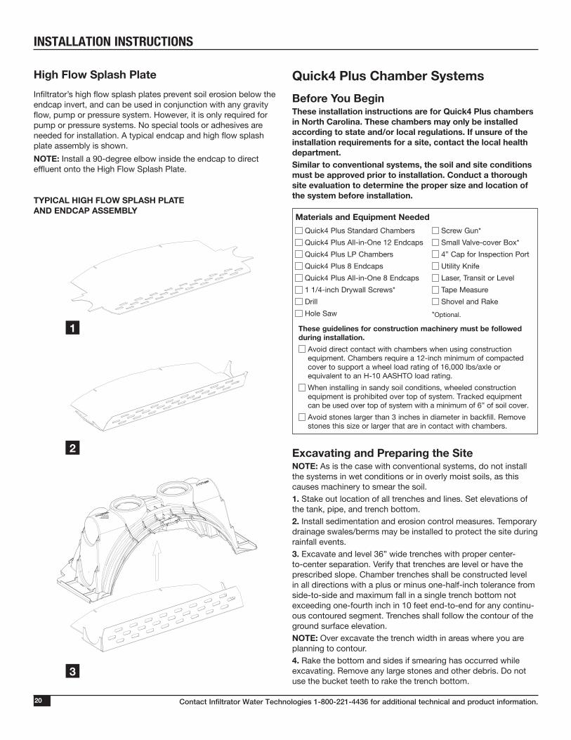
INSTALLATION INSTRUCTIONS
High Flow Splash PlateInfiltrator’s high flow splash plates prevent soil erosion below the endcap invert, and can be used in conjunction with any gravity flow, pump or pressure system. However, it is only required for pump or pressure systems. No special tools or adhesives are needed for installation. A typical endcap and high flow splash plate assembly is shown.NOTE: Install a 90-degree elbow inside the endcap to direct effluent onto the High Flow Splash Plate.
TYPICAL HIGH FLOW SPLASH PLATE AND ENDCAP ASSEMBLY
1
12
3
Quick4 Plus Chamber SystemsBefore You BeginThese installation in struc tions are for Quick4 Plus chambers in North Carolina. These chambers may only be installed according to state and/or local regulations. If unsure of the installation requirements for a site, contact the local health department. Similar to conventional systems, the soil and site conditions must be approved prior to installation. Conduct a thorough site evaluation to determine the proper size and location of the system before installation.
Excavating and Preparing the SiteNOTE: As is the case with conventional systems, do not install the systems in wet conditions or in overly moist soils, as this causes machinery to smear the soil.1. Stake out location of all trenches and lines. Set elevations of the tank, pipe, and trench bottom.2. Install sedimentation and erosion control measures. Temporary drainage swales/berms may be installed to protect the site during rainfall events. 3. Excavate and level 36” wide trenches with proper center-to-center separation. Verify that trenches are level or have the prescribed slope. Chamber trenches shall be constructed level in all directions with a plus or minus one-half-inch tolerance from side-to-side and maximum fall in a single trench bottom not exceeding one-fourth inch in 10 feet end-to-end for any continu-ous contoured segment. Trenches shall follow the contour of the ground surface elevation.NOTE: Over excavate the trench width in areas where you are planning to contour.4. Rake the bottom and sides if smearing has occurred while excavating. Remove any large stones and other debris. Do not use the bucket teeth to rake the trench bottom.
Materials and Equipment Needed Quick4 Plus Standard Chambers Screw Gun* Quick4 Plus All-in-One 12 Endcaps Small Valve-cover Box* Quick4 Plus LP Chambers 4” Cap for Inspection Port Quick4 Plus 8 Endcaps Utility Knife Quick4 Plus All-in-One 8 Endcaps Laser, Transit or Level 1 1/4-inch Drywall Screws* Tape Measure Drill Shovel and Rake Hole Saw *Optional.
These guidelines for construction machinery must be followed during installation.
Avoid direct contact with chambers when using construction equipment. Chambers require a 12-inch minimum of compacted cover to support a wheel load rating of 16,000 lbs/axle or equivalent to an H-10 AASHTO load rating.
When installing in sandy soil conditions, wheeled construction equipment is prohibited over top of system. Tracked equipment can be used over top of system with a minimum of 6” of soil cover.
Avoid stones larger than 3 inches in diameter in backfill. Remove stones this size or larger that are in contact with chambers.
Contact Infiltrator Water Technologies 1-800-221-4436 for additional technical and product information. 21
INSTALLATION INSTRUCTIONSNOTE: Raking to eliminate smearing is not necessary in sandy soils. In fine textured soils (silts and clays), avoid walking in the trench to prevent compaction and loss of soil structure.5. Verify levelness for each trench using a level, transit or laser.
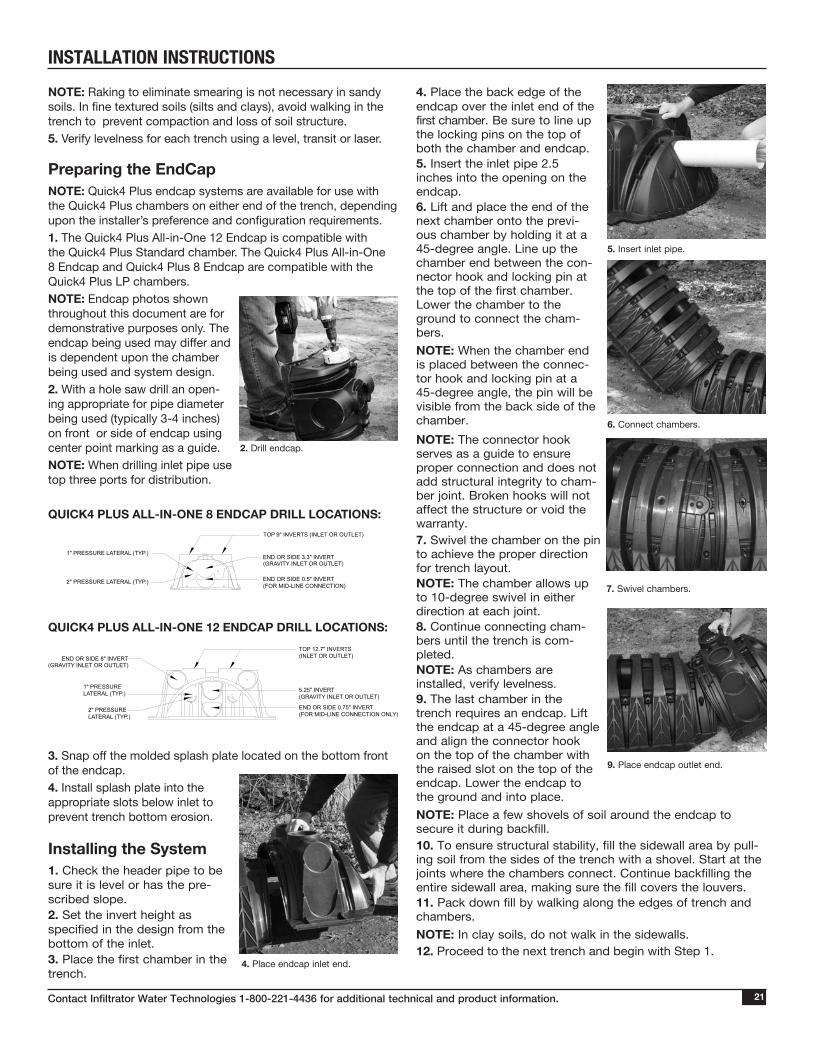
Preparing the EndCapNOTE: Quick4 Plus endcap systems are available for use with the Quick4 Plus chambers on either end of the trench, depending upon the installer’s preference and configuration requirements.1. The Quick4 Plus All-in-One 12 Endcap is compatible with the Quick4 Plus Standard chamber. The Quick4 Plus All-in-One 8 Endcap and Quick4 Plus 8 Endcap are compatible with the Quick4 Plus LP chambers.NOTE: Endcap photos shown throughout this document are for demonstrative purposes only. The endcap being used may differ and is dependent upon the chamber being used and system design.2. With a hole saw drill an open-ing appropriate for pipe diameter being used (typically 3-4 inches) on front or side of endcap using center point marking as a guide. NOTE: When drilling inlet pipe use top three ports for distribution.
QUICK4 PLUS ALL-IN-ONE 8 ENDCAP DRILL LOCATIONS:
QUICK4 PLUS ALL-IN-ONE 12 ENDCAP DRILL LOCATIONS:
3. Snap off the molded splash plate located on the bottom front of the endcap.4. Install splash plate into the appropriate slots below inlet to prevent trench bottom erosion.
Installing the System1. Check the header pipe to be sure it is level or has the pre-scribed slope.2. Set the invert height as specified in the design from the bottom of the inlet.3. Place the first chamber in the trench.
2. Drill endcap.
1" PRESSURE LATERAL (TYP.)
2" PRESSURE LATERAL (TYP.)
END OR SIDE 3.3" INVERT(GRAVITY INLET OR OUTLET)
END OR SIDE 0.5" INVERT(FOR MID-LINE CONNECTION)
TOP 9" INVERTS (INLET OR OUTLET)
2" PRESSURE LATERAL (TYP.)
1" PRESSURE LATERAL (TYP.) 5.25" INVERT
(GRAVITY INLET OR OUTLET)
TOP 12.7" INVERTS(INLET OR OUTLET)END OR SIDE 8" INVERT
(GRAVITY INLET OR OUTLET)
END OR SIDE 0.75" INVERT (FOR MID-LINE CONNECTION ONLY)
4. Place the back edge of the endcap over the inlet end of the first chamber. Be sure to line up the locking pins on the top of both the chamber and endcap.5. Insert the inlet pipe 2.5 inches into the opening on the endcap.6. Lift and place the end of the next chamber onto the previ-ous chamber by holding it at a 45-degree angle. Line up the chamber end between the con-nector hook and locking pin at the top of the first chamber. Lower the chamber to the ground to connect the cham-bers. NOTE: When the chamber end is placed between the connec-tor hook and locking pin at a 45-degree angle, the pin will be visible from the back side of the chamber. NOTE: The connector hook serves as a guide to ensure proper connection and does not add structural integrity to cham-ber joint. Broken hooks will not affect the structure or void the warranty.7. Swivel the chamber on the pin to achieve the proper direction for trench layout.NOTE: The chamber allows up to 10-degree swivel in either direction at each joint.8. Continue connecting cham-bers until the trench is com-pleted.NOTE: As chambers are installed, verify levelness.9. The last chamber in the trench requires an endcap. Lift the endcap at a 45-degree angle and align the connector hook on the top of the chamber with the raised slot on the top of the endcap. Lower the endcap to the ground and into place.NOTE: Place a few shovels of soil around the endcap to secure it during backfill.10. To ensure structural stability, fill the sidewall area by pull-ing soil from the sides of the trench with a shovel. Start at the joints where the chambers connect. Continue backfilling the entire sidewall area, making sure the fill covers the louvers.11. Pack down fill by walking along the edges of trench and chambers.NOTE: In clay soils, do not walk in the sidewalls.12. Proceed to the next trench and begin with Step 1.
7. Swivel chambers.
9. Place endcap outlet end.
4. Place endcap inlet end.
5. Insert inlet pipe.
6. Connect chambers.
Contact Infiltrator Water Technologies 1-800-221-4436 for additional technical and product information.22
INSTALLATION INSTRUCTIONS
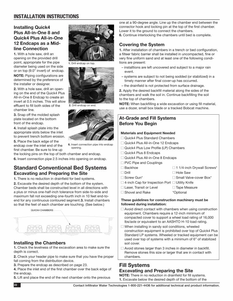
Installing Quick4 Plus All-in-One 8 and Quick4 Plus All-in-One 12 Endcaps as a Mid-line Connection1. With a hole saw, drill an opening on the provided drill point, appropriate for the pipe diameter being used on the side or on top (9.0” invert) of endcap.NOTE: Piping configurations are determined by the preference of the installer or designer. 2. With a hole saw, drill an open-ing on the end of the Quick4 Plus All-in-One 8 Endcap to create an invert at 0.5 inches. This will allow effluent to fill both sides of the chamber line.3. Snap off the molded splash plate located on the bottom front of the endcap.4. Install splash plate into the appropriate slots below the inlet to prevent trench bottom erosion.5. Place the back edge of the endcap over the inlet end of the first chamber. Be sure to line up the locking pins on the top of both chamber and endcap.6. Insert connection pipe 2.5 inches into opening on endcap. Standard Conventional Bed Systems Excavating and Preparing the Site1. There is no reduction in drainfield for bed systems.2. Excavate the desired depth of the bottom of the system. Chamber beds shall be constructed level in all directions with a plus or minus one-half-inch tolerance from side-to-side and maximum fall not exceeding one-fourth inch in 10 feet end-to-end for any continuous contoured segment.3. Install chambers so that the feet of each chamber are touching. (See below.) Installing the Chambers 1. Check the levelness of the excavation area to make sure the depth is correct.2. Check your header pipe to make sure that you have the proper fall coming from the distribution device.3. Prepare the endcap as described on page 23.4. Place the inlet end of the first chamber over the back edge of the endcap.5. Lift and place the end of the next chamber onto the previous
one at a 90-degree angle. Line up the chamber end between the connector hook and locking pin at the top of the first chamber. Lower it to the ground to connect the chambers.6. Continue interlocking the chambers until bed is complete.
Covering the System 1. After installation of chambers in a trench or bed configuration, a filteer fabric barrier shall be installed in uncompacted, fine or very fine uniform sand and at least one of the following condi-tions are present:
– installtions are left uncovered and subject to a major rain event.
– systems are subject to not being sodded (or stabilized) in a timely manner after final cover-up has occurred.
– the drainfield is not protected from surface drainage.2. Apply the desired backfill material along the sides of the chambers and walk the soil in. Continue backfilling the soil to the top of chambers.NOTE: When backfilling a wide excavation or using fill material, use a dozer, small box blade or a tracked Bobcat machine. At-Grade and Fill Systems Before You Begin Materials and Equipment Needed
Quick4 Plus Standard Chambers Quick4 Plus All-in-One 12 Endcaps Quick4 Plus Low Profile (LP) Chambers Quick4 Plus 8 Endcaps Quick4 Plus All-in-One 8 Endcaps PVC Pipe and Couplings Backhoe 1 1/4-inch Drywall Screws* Drill Hole Saw Screw Gun* Small Valve-cover Box* 4-inch Cap for Inspection Port Utility Knife Laser, Transit or Level Tape Measure Shovel and Rake *Optional
These guidelines for construction machinery must be followed during installation:
Avoid direct contact with chambers when using construction equipment. Chambers require a 12-inch minimum of compacted cover to support a wheel load rating of 16,000 lbs/axle or equivalent to an AASHTO H-10 load rating.
When installing in sandy soil conditions, wheeled construction equipment is prohibited over top of Quick4 Plus Standard LP systems. Wheeled or tracked equipment can be used over top of systems with a minimum of 6” of stabilized soil cover. Avoid stones larger than 3 inches in diameter in backfill. Remove stones this size or larger that are in contact with chambers.
Fill Systems Excavating and Preparing the SiteNOTE: There in no reduction in drainfield for fill systems. 1. Excavate below the desired depth of the bottom of the
2. Drill endcap on end.
6. Insert connection pipe into endcap opening.
QUICK4 CHAMBERS
1. Drill endcap on top.

Contact Infiltrator Water Technologies 1-800-221-4436 for additional technical and product information. 23
INSTALLATION INSTRUCTIONSchamber for both trench and wide excavations, per the rules and permit.NOTE: Always stabilize sandy, loamy (Group I) soils.2. Use a coarse grain sand to create desired trench bottom elevation.3. Stabilize soil before installing chambers.
Installing the System1. Check the header pipe to be sure it is level or has the prescribed slope.2. Set the invert height as speci-fied in the design from the bot-tom of the inlet.3. Place the first chamber in the trench. 4. Place the back edge of the endcap over the inlet end of the first chamber. Be sure to line up the locking pins on the top of both chamber and endcap.Optional: Fasten the endcap to the chamber with a screw at the top of the endcap.5. Insert the inlet pipe 2.5 inches into the opening on the endcap.6. Lift and place the end of the next chamber onto the previ-ous chamber by holding it at a 45-degree angle. Line up the chamber end between the connector hook and locking pin at the top of the first cham-ber. Lower the chamber to the ground to connect chambers. NOTE: When the chamber end is placed between the connec-tor hook and locking pin at a 45-degree angle, the pin will be visible from the back side of the chamber. NOTE: The connector hook serves as a guide to ensure proper connection and does not add structural integrity to cham-ber joint. Broken hooks will not affect structure or void warranty.7. Swivel the chamber on the pin to achieve the proper direction for trench layout.NOTE: The chamber allows up to 10-degree swivel in either direction at each joint.8. Continue connecting cham-bers until the trench is com-pleted.NOTE: As the chambers are installed, verify that they are level or
have the prescribed slope. 9. The last chamber in the trench requires an endcap. Lift the endcap at a 45-degree angle and align the connector hook on the top of the chamber with the raised slot on the top of the end-cap. Lower the endcap to the ground and into place.NOTE: Place a few shovels of soil around the endcap to secure it during backfill.10. To ensure structural stability, fill the sidewall area by pulling soil from the sides of the trench with a shovel. Start at the joints where the chambers connect. Continue backfilling the entire sidewall area, making sure the fill covers the louvers.11. Pack down fill by walking along the edges of trench and chambers.NOTE: In wet or clay soils, do not walk in the sidewalls.
Installing Inspection PortsInspection ports may be installed on the chamber, the Quick4 Plus All-in-One 8 Endcap or the Quick4 Plus All-in-One 12 Endcap. The inspection port(s) are not intended to function for the purpose of ventilation.
ENDCAP INSPECTION PORT1. With a hole saw drill the pre-marked area in the top of the endcap to create a 4 1/3 to 4 1/2-inch opening based on pipe type.2. Set a cut piece of pipe of the appropriate length into the cor-responding endcap’s inspection port sleeve.NOTE: Sleeve will accommodate up to a 4-inch Schedule 40 pipe. 3. Use two screws to fasten the pipe to the sleeve around the inspection port.4. Attach a threaded cap or cleanout assembly onto the protrud-ing pipe at the appropriate height.5. A small valve cover box may be used if the inspection port is below the desired grade.
CHAMBER INSPECTION PORT1. With a hole saw drill the pre-marked area in the top of the chamber to create a 2.5-inch opening.2. Set a cut piece of pipe of the appropriate length into the cor-responding chamber’s inspec-tion port sleeve.3. Use two screws to fasten the pipe to the sleeve around the inspection port.4. Attach a threaded cap or cleanout assembly onto the protrud-ing pipe at the appropriate height.5. A small valve cover box may be used if the inspection port is below the desired grade.
9. Place endcap outlet end.
6. Connect chambers.
4. Place endcap inlet end.
5. Insert inlet pipe.Endcap inspection port, top.
Chamber inspection port.

Contact Infiltrator Water Technologies 1-800-221-4436 for additional technical and product information.24
INSTALLATION INSTRUCTIONSNOTE: Endcap photos shown throughout this document are for demonstrative purposes only. The endcap being used may differ and is dependent upon the chamber being used and system design.2. To allow pressure laterals to drain after each dose, drill a hole in the bottom of the pipe at the end of the pressure line. Place the snap-off splash plate or a paving block at the bottom of trench to protect infiltrative surface from erosion. QUICK4 PLUS ALL-IN-ONE 8 ENDCAP DRILL LOCATIONS:
QUICK4 PLUS ALL-IN-ONE 12 ENDCAP DRILL LOCATIONS:
3. With a hole saw, drill out the appropriate diameter hole to accommodate the pressure lateral pipe. 4. Insert the pressure lateral pipe into the endcap’s drilled open-ing and slide it into the manifold pipe. Glue the pressure lateral pipe to the manifold pipe. 5. With the pressure lateral pipe through the endcap, place the back edge of the endcap over the inlet end of the first chamber. Be sure to line up the locking pins on the top of both the cham-ber and endcap. NOTE: Health departments may require a wet-run pressure check to be done prior to chamber installation when the pipe is laying on the ground. Check with your local health department for the proper procedure.
6. Method A Secure the pressure lateral pipe to the top of the first chamber with a plastic pipe strap at the outlet end of the unit. Slide the strap up through a slot in the chamber top, down through the other slot, and cinch the two ends around the pipe. 7. Lift and place the next cham-ber onto the previous one at a 45-degree angle. Line up the chamber end between the connector hook and locking pin at the top of the first chamber. Lower it to the ground to engage the interlocks.
Covering the System1. Apply the desired backfill material along the sides of the chambers and walk the soil in. Continue backfilling the soil to the top of chambers.NOTE: When backfilling a wide excavation or soil substitution system use a dozer, small box blade or a tracked vehicle.NOTE: For At-Grade or Capped Systems, Infiltrator Water Tech-nologies requires a minimum of six inches of approved capping material.NOTE: For Fill Systems, Infiltrator Water Technologies recom-mends but does not require the fill to be in place and allowed adequate time to settle before installation.
Low Pressure Piping Systems This section provides septic installation instructions for low pres-sure piping systems in North Carolina. Quick4 Plus chambers can only be installed according to state and/or local regulations. Contact your local regulator for specific requirements. Soil and site conditions must be approved prior to installation. Conduct a thorough site evaluation to determine proper sizing and siting of the system before installation.
Materials and Equipment Needed Quick4 Plus Standard Chambers Quick4 Plus All-in-One 12 Endcaps Quick4 Plus Low Profile (LP) Chambers Quick4 Plus 8 Endcaps Quick4 Plus All-in-One 8 Endcaps PVC Pipe and Couplings Backhoe 1 1/4-inch Drywall Screws* Drill Hole Saw Screw Gun* Small Valve-cover Box* 4-inch Cap for Inspection Port Utility Knife Laser, Transit or Level Tape Measure Shovel and Rake *Optional
These guidelines for construction machinery must be followed during installation:
Avoid direct contact with chambers when using construction equipment. Chambers require a 12-inch minimum of compacted cover to support a wheel load rating of 16,000 lbs/axle or equivalent to an AASHTO H-10 load rating. When installing in sandy soil conditions, wheeled construction equipment is prohibited over top of Quick4 Plus Standard LP chamber systems. Wheeled or tracked equip-ment can be used over top of system with a minimum of 6” of stabilized soil cover. Avoid stones larger than 3 inches in diameter in backfill. Remove stones this size or larger that are in contact with chambers.
Installing the Chambers and Endcaps1. The Quick4 Plus All-in-One 12 Endcap is compatible with the Quick4 Plus Standard chamber. The Quick4 Plus All-in-One 8 Endcap and Quick4 Plus 8 Endcap are compatible with the Quick4 Plus LP chambers.
1" PRESSURELATERAL (TYP.)
2" PRESSURELATERAL (TYP.)
END OR SIDE 3.3" INVERT(GRAVITY INLET OR OUTLET)
TOP 9" INVERTS (INLET OR OUTLET)
2" PRESSURE LATERAL (TYP.)
1" PRESSURE LATERAL (TYP.)
5.25" INVERT (GRAVITY INLET OR OUTLET)
TOP 12.7" INVERTS(INLET OR OUTLET)END OR SIDE
8" INVERT(GRAVITY INLET OR OUTLET)
END OR SIDE 0.75" INVERT (FOR MID-LINE CONNECTION ONLY)
END OR SIDE 0.5" INVERT (FOR MID-LINE CONNECTION ONLY)
6. Secure pressure pipe.
3. Drill pressure pipe location.
Contact Infiltrator Water Technologies 1-800-221-4436 for additional technical and product information. 25
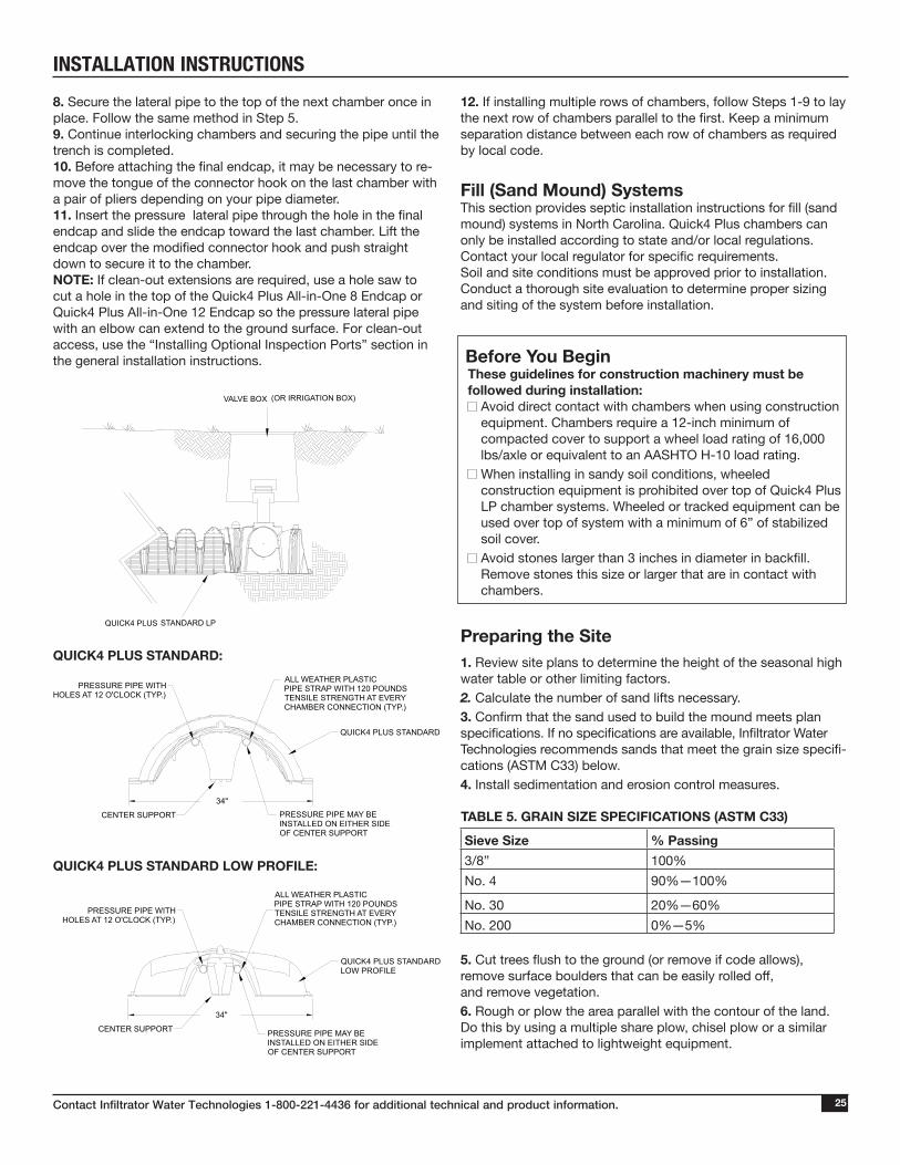
INSTALLATION INSTRUCTIONS8. Secure the lateral pipe to the top of the next chamber once in place. Follow the same method in Step 5. 9. Continue interlocking chambers and securing the pipe until the trench is completed.10. Before attaching the final endcap, it may be necessary to re-move the tongue of the connector hook on the last chamber with a pair of pliers depending on your pipe diameter. 11. Insert the pressure lateral pipe through the hole in the final endcap and slide the endcap toward the last chamber. Lift the endcap over the modified connector hook and push straight down to secure it to the chamber.NOTE: If clean-out extensions are required, use a hole saw to cut a hole in the top of the Quick4 Plus All-in-One 8 Endcap or Quick4 Plus All-in-One 12 Endcap so the pressure lateral pipe with an elbow can extend to the ground surface. For clean-out access, use the “Installing Optional Inspection Ports” section in the general installation instructions.
12. If installing multiple rows of chambers, follow Steps 1-9 to lay the next row of chambers parallel to the first. Keep a minimum separation distance between each row of chambers as required by local code.
Fill (Sand Mound) Systems This section provides septic installation instructions for fill (sand mound) systems in North Carolina. Quick4 Plus chambers can only be installed according to state and/or local regulations. Contact your local regulator for specific requirements. Soil and site conditions must be approved prior to installation. Conduct a thorough site evaluation to determine proper sizing and siting of the system before installation.
Before You BeginThese guidelines for construction machinery must be followed during installation:
Avoid direct contact with chambers when using construction equipment. Chambers require a 12-inch minimum of compacted cover to support a wheel load rating of 16,000 lbs/axle or equivalent to an AASHTO H-10 load rating.
When installing in sandy soil conditions, wheeled construction equipment is prohibited over top of Quick4 Plus LP chamber systems. Wheeled or tracked equipment can be used over top of system with a minimum of 6” of stabilized soil cover. Avoid stones larger than 3 inches in diameter in backfill. Remove stones this size or larger that are in contact with chambers.
Preparing the Site1. Review site plans to determine the height of the seasonal high water table or other limiting factors.2. Calculate the number of sand lifts necessary. 3. Confirm that the sand used to build the mound meets plan specifications. If no specifications are available, Infiltrator Water Technologies recommends sands that meet the grain size specifi-cations (ASTM C33) below.4. Install sedimentation and erosion control measures.
TABLE 5. GRAIN SIZE SPECIFICATIONS (ASTM C33)
Sieve Size % Passing3/8” 100%No. 4 90%—100%
No. 30 20%—60%No. 200 0%—5%
5. Cut trees flush to the ground (or remove if code allows), remove surface boulders that can be easily rolled off, and remove vegetation.6. Rough or plow the area parallel with the contour of the land. Do this by using a multiple share plow, chisel plow or a similar implement attached to lightweight equipment.
VALVE BOX (OR IRRIGATION BOX)
ACCESS FOR DRAINFIELD MAINTENANCE AND FLUSHING
QUICK4 PLUS STANDARD LP
CENTER SUPPORT PRESSURE PIPE MAY BE INSTALLED ON EITHER SIDE OF CENTER SUPPORT
34"
34"
ALL WEATHER PLASTICPIPE STRAP WITH 120 POUNDSTENSILE STRENGTH AT EVERY CHAMBER CONNECTION (TYP.)
PRESSURE PIPE WITH HOLES AT 12 O'CLOCK (TYP.)
QUICK4 PLUS STANDARD
QUICK4 PLUS STANDARDLOW PROFILE
PRESSURE PIPE MAY BE INSTALLED ON EITHER SIDE OF CENTER SUPPORT
PRESSURE PIPE WITH HOLES AT 12 O'CLOCK (TYP.)
ALL WEATHER PLASTICPIPE STRAP WITH 120 POUNDSTENSILE STRENGTH AT EVERY CHAMBER CONNECTION (TYP.)
CENTER SUPPORT
QUICK4 PLUS STANDARD:
QUICK4 PLUS STANDARD LOW PROFILE:

Contact Infiltrator Water Technologies 1-800-221-4436 for additional technical and product information.26
INSTALLATION INSTRUCTIONS
INSPECTOR’S CHECKLIST
Placing the Sand1. Use a dozer or backhoe to evenly spread a six-inch lift of specified fill material over required area.2. Each sand lift must be compacted. The contractor determines the means and methods necessary to stabilize fill and attain required compaction. NOTE: Compaction is critical to prevent settling and will not have a significant effect on permeability of clean, sandy fill.3. Place consecutive lifts following Steps 1 and 2 until design elevation is achieved (desired elevation is the infiltrative surface). Lifts should not exceed a 6-inch height.4. Lightly drag a landscape rake over the final infiltrative surface to scarify the top 1⁄2 inch of sand. Check bed elevation to be sure it is constructed level in all directions with a plus or minus one-half-inch tolerance from side-to-side and maximum fall not exceeding one-fourth inch in 10 feet end-to-end for any continu-ous segment. Installing Chambers, Pressure Pipes and Endcaps1. To allow pressure laterals to drain after each cycle, drill holes in the bottom end of the pipe. Place a splash plate or a paving block at the bottom of the trench to protect the infiltrative surface from erosion.2. Create the appropriately-sized hole in the endcap at the proper elevation. Insert the pressure lateral pipe into the end plate hole and slide it into the manifold pipe. 3. Glue the pressure lateral pipe to the manifold pipe.NOTE: Health Departments may require a pressure check. This may be done prior to chamber installation, when the pipe is lay-ing on the ground. Check with your local Health Department for the proper procedure.4. Secure the pressure lateral pipe to the top of the first chamber with a plastic pipe strap at the outlet end of the unit. Slide the strap up through a slot in the chamber top, down through the other slot, and cinch the two ends around the pipe. 5. Lift and place the next chamber onto the previous one at a 90-degree angle. Line up the chamber end between the connec-tor hook and locking pin at the top of the first chamber. Lower it to the ground to en-gage the interlocks.6. Secure the lateral pipe to the top of the chamber once in place. Follow the same meth-od as described in Step 4.7. Continue interlocking cham-bers and pipe until trench is completed.8. Attach an endcap to the last chamber in the trench. If clea-nout extensions are required, create a hole in the endcap at the proper elevation to allow the lateral pipe to extend. For leanout access, a 90° elbow that extends to the soil’s surface can
be attached to the lateral pipe.9. Follow Steps 1-8 for all trenches or rows in the permitted system.
Covering the SystemNOTE: Before backfilling, the system must be in spected by a health or regulatory official as required by state and local codes. Create an as-built drawing at this time for future records.1. Place berm material around the perimeter of the sand mound and directly against the outer rows of chambers for stabilization. 2. Ladle soil between the chamber rows to the top sidewall louver to prevent chamber movement before final backfill. Firm the soil between the chamber rows by walking it in. This important step assures correct structural support of the system.3. Push the berm material between and over the chamber rows with a dozer. Keep a minimum 6 inches of compacted cover over the system. NOTE: NO wheeled machinery is allowed on Quick4 Plus Stan-dard LP chambers in mounds.4. After the system is covered, the site should be seeded or sodded to produce erosion-resistant vegetation.NOTE: If the system is for new home construction, it is important to leave marking stakes along the boundary of the system. This will notify contractors of the site location so they will not cross it with equipment or vehicles.
The following checklist may be used when inspecting Quick4 chambers.
1. Check for level distribution device and watertight connections.
2. Confirm distribution lines (manifold header pipes) have been primed and glued for securing.
3. Confirm distribution lines have been properly bedded and secured into endcap.
4. Determine correct length of lines.
5. Inspections: a. Sidewalls have been carefully walked in b. Visually inspect chamber joints c. Confirm step-downs are properly bedded d. Verify trench depth
6. Shoot trench grade at top of chamber or from side of chamber foot at the trench bottom.
Chamber trenches shall be constructed level in all directions with a plus or minus one-half-inch tolerance from side-to-side and maximum fall in a single trench bottom not exceeding one-fourth inch in 10 feet end-to-end for any continuous contoured segment. Trenches shall follow the contour of the ground surface elevation.
7. Always run pump before issuing Operations Permit (OP). a. Run draw down test to verify correct dosing volume.
4. Secure lateral pipe to the top of the chamber.

WARRANTY
Contact Infiltrator Water Technologies 1-800-221-4436 for additional technical and product information. 27
(a) The structural integrity of each chamber, endcap and other acces-sory manufactured by Infiltrator (collectively referred to as “Units”), when installed and operated in a leachfield of an onsite septic system in accor-dance with Infiltrator’s installation instructions, is warranted to the original purchaser (“Holder”) against defective materials and workmanship for one year from the date upon which a Septic Operation Permit is issued for the septic system containing the Units; provided, however, that if a septic permit is not required for the septic system by applicable law, the one (1) year warranty period will begin upon the date that installation of the septic system commences. In order to exercise its warranty rights, Holder must notify Infiltrator in writing at its corporate headquarters in Old Saybrook, Connecticut within fifteen (15) days of the alleged defect. Infiltrator will supply replacement Units for those Units determined by Infiltrator to be defective and covered by this Limited Warranty. Infiltrator’s liability specifi-cally excludes the cost of removal and/or installation of the Units.
(b) THE LIMITED WARRANTY AND REMEDIES IN SUBPARAGRAPH (a) ARE EXCLUSIVE. THERE ARE NO OTHER WARRANTIES WITH RESPECT TO THE UNITS, INCLUDING NO IMPLIED WARRANTIES OF MERCHANTABILITY OR FITNESS FOR A PARTICULAR PURPOSE.
(c) This Limited Warranty shall be void if any part of the chamber system (chamber, endcap or other accessory) is manufactured by anyone other than Infiltrator. The Limited Warranty does not extend to incidental, con-sequential, special or indirect damages. Infiltrator shall not be liable for penalties or liquidated damages, including loss of production and profits, labor and materials, overhead costs, or other losses or expenses incurred by the Holder or any third party. Specifically excluded from Limited War-
ranty coverage are damage to the Units due to ordinary wear and tear, alteration, accident, misuse, abuse or neglect of the Units; the Units be-ing subjected to vehicle traffic or other conditions which are not permitted by the installation instructions; failure to maintain the minimum ground covers set forth in the installation instructions; the placement of improper materials into the system containing the Units; failure of the Units or the septic system due to improper siting or improper sizing, excessive water usage, improper grease disposal, or improper operation; or any other event not caused by Infiltrator. This Limited Warranty shall be void if the Holder fails to comply with all of the terms set forth in this Limited Warranty.
Further, in no event shall Infiltrator be responsible for any loss or damage to the Holder, the Units, or any third party resulting from installation or shipment, or from any product liability claims of Holder or any third party. For this Limited Warranty to apply, the Units must be installed in accor-dance with all site conditions required by state and local codes; all other applicable laws; and Infiltrator’s installation instructions.
(d) No representative of Infiltrator has the authority to change this Limited Warranty in any manner whatsoever, or to extend this Limited Warranty. No warranty applies to any party other than the original Holder.
The above represents the standard Limited Warranty offered by Infiltrator. A limited number of states and counties have different warranty require-ments. Any purchaser of Units should contact Infiltrator’s corporate head-quarters in Old Saybrook, Connecticut, prior to such purchase, to obtain a copy of the applicable warranty, and should carefully read that warranty prior to the purchase of Units.
INFILTRATOR WATER TECHNOLOGIES STANDARD LIMITED DRAINFIELD WARRANTY
(a) This limited warranty is extended to the end user of an Infiltrator Septic Tank. A Septic Tank manufactured by Infiltrator, when installed and operated in accordance with Infiltrator’s installation instructions and local regulation by a licensed installer, is warranted to you: (i) against defective materials and workmanship for five (5) years after installation. Infiltrator will, at its option, (i) repair the defective product or (ii) replace the defec-tive materials. Infiltrator’s liability specifically excludes the cost of removal and/or installation of the Septic Tank.(b) In order to exercise its warranty rights, you must notify Infiltrator in writing at its corporate headquarters in Old Saybrook, Connecticut within fifteen (15) days of the alleged defect.(c) YOUR EXCLUSIVE REMEDY WITH RESPECT TO ANY AND ALL LOSSES OR DAMAGES RESULTING FROM ANY CAUSE WHATSOEV-ER SHALL BE SPECIFIED IN SUBPARAGRAPH (a) ABOVE. INFILTRA-TOR SHALL IN NO EVENT BE LIABLE FOR ANY CONSEQUENTIAL OR INCIDENTAL DAMAGES OF ANY KIND, HOWEVER OCCASIONED, WHETHER BY NEGLIGENCE OR OTHERWISE. SOME STATES DO NOT ALLOW THE EXCLUSION OR LIMITATION OF INCIDENTAL OR CONSEQUENTIAL DAMAGES, SO THIS LIMITATION OR EXCLUSION MAY NOT APPLY TO YOU. THIS WARRANTY GIVES YOU SPECIFIC LEGAL RIGHTS AND YOU MAY ALSO HAVE OTHER RIGHTS WHICH VARY FROM STATE TO STATE. (d) THIS LIMITED WARRANTY IS THE EXCLUSIVE WARRANTY GIVEN BY INFILTRATOR AND SUPERSEDES ANY PRIOR, CONTRARY, AD-DITIONAL, OR SUBSEQUENT REPRESENTATIONS, WHETHER ORAL OR WRITTEN. INFILTRATOR DISCLAIMS AND EXCLUDES TO THE GREATEST EXTENT ALLOWED BY LAW ALL OTHER WARRANTIES, WHETHER EXPRESS OR IMPLIED, OR STATUTORY, INCLUDING ANY WARRANTY OF MERCHANTABILITY, FINESSE FOR A PARTICULAR PURPOSE AND ANY IMPLIED WARRANTIES OTHERWISE ARISING
FROM COURSE OF DEALING, COURSE OF PERFORMANCE, OR US-AGE OF TRADE. NO PERSON (INCLUDING ANY EMPLOYEE, AGENT, DEALER, OR REPRESENTATIVE) IS AUTHORIZED TO MAKE ANY REPRESENTATION OR WARRANTY CONCERNING THIS PRODUCT, EXCEPT TO REFER YOU TO THIS LIMITED WARRANTY. EXCEPT AS EXPRESSLY SET FORTH HEREIN, THIS WARRANTY IS NOT A WAR-RANTY OF FUTURE PERFORMANCE, BUT ONLY A WARRANTY TO REPAIR OR REPLACE. (e) YOU MAY ASSIGN THIS LIMITED WARRANTY TO A SUBSEQUENT PURCHASER OF YOUR HOME.(f) NO REPRESENTATIVE OF INFILTRATOR HAS THE AUTHORITY TO CHANGE THIS LIMITED WARRANTY IN ANY MANNER WHATSO-EVER, OR TO EXTEND THIS LIMITED WARRANTY.
CONDITIONS AND EXCLUSIONSThere are certain conditions or applications over which Infiltrator has no control. Defects or problems as a result of such conditions or applications are not the responsibility of Infiltrator and are NOT covered under this warranty. They include failure to install the Septic Tank in accordance with instructions or applicable regulatory requirements or guidance, altering the Septic Tank contrary to the installation instructions and disposing of chemicals or other materials contrary to normal septic tank usage.
The above represents the Standard Limited Warranty offered by Infiltrator. A limited number of states and counties have different warranty require-ments. Any purchaser of a Septic Tank should contact Infiltrator’s corpo-rate headquarters in Old Saybrook, Connecticut, prior to such purchase to obtain a copy of the applicable warranty, and should carefully read that warranty prior to the purchase of a Septic Tank.
INFILTRATOR WATER TECHNOLOGIES (“INFILTRATOR”)INFILTRATOR® SEPTIC TANK LIMITED WARRANTY FIVE (5) YEAR MATERIALS AND WORKMANSHIP LIMITED WARRANTY

Contact Infiltrator Water Technologies’ Technical Services Department for assistance at 1-800-221-4436
4 Business Park Road P.O. Box 768 Old Saybrook, CT 06475860-577-7000 • Fax 860-577-70011-800-221-4436www.infiltratorwater.com
U.S. Patents: 4,759,661; 5,017,041; 5,156,488; 5,336,017; 5,401,116; 5,401,459; 5,511,903; 5,716,163; 5,588,778; 5,839,844 Canadian Patents: 1,329,959; 2,004,564 Other patents pending. Infiltrator, Equalizer, Quick4, and SideWinder are registered trademarks of Infiltrator Water Technologies. Infiltrator is a registered trademark in France. Infiltrator Water Technologies is a registered trademark in Mexico. Contour, MicroLeaching, PolyTuff, ChamberSpacer, MultiPort, PosiLock, QuickCut, QuickPlay, SnapLock and StraightLock are trademarks of Infiltrator Water Technologies. PolyLok is a trademark of PolyLok, Inc. TUF-TITE is a registered trademark of TUF-TITE, INC. Ultra-Rib is a trademark of IPEX Inc. © 2015 Infiltrator Water Technologies, LLC. All rights reserved. Printed in U.S.A. C43 0715ISI