design and implementation of openstack hack-lab
TRANSCRIPT

Mwaura Gerald
Design and Implementation of OpenStack Hack-Lab
Metropolia University of Applied Sciences
Bachelor of Engineering
Degree Programme
Thesis
9 April 2018

Abstract
Author Title Number of Pages Date
Mwaura Gerald Design and Implementation of OpenStack Hack-Lab 34 pages + 6 appendices 09 April 2018
Degree Bachelor of Engineering
Degree Program Information Technology
Professional Major Communications and Networking Software Engineering
Instructors
Kimmo Sauren, Principal Lecturer
The goal of the thesis was to design and implement a cloud platform on which to run an open-source pen-testing lab. This would be done with minimal monetary investment and tools that are readily available. This is to stay in line with the primary objective of who the implementation if for and intended use. The theoretical part discusses the enabling technology of cloud computing and virtualisation with a practical part at the end on the implementation of the lab. OpenStack was the preferred platform for reasons discussed in the thesis herein. OpenStack as an open-source software was found to be making good head way to becoming among the top software for cloud and data centres. The core projects behind OpenStack could be combined to develop an easy do it yourself security testing laboratory. The lab will comprise of a combination of vulnerable images used to create servers held within self assigned networks. These networks can be configured in a way to offer challenge to penetration testers within the platform. The platform can hold multiple labs an advantage of using cloud services. This and other advantages allowed by using cloud services are the essential features this thesis basis itself on and will be discussed as part of the thesis. The result of the project is a cloud platform based on OpenStack offering a security experience to any individual interested hacking in general. Service components will be added for administration and control of the components and any future expansion of the project.
Keywords OpenStack, Cloud computing, SDN, Open source, Cyber security, Penetration Testing

Contents
List of Abbreviations
1 Introduction 1
2 Current Analysis of Available Solutions 2
3 Cloud Computing and Virtualization 3
3.1 Virtualization 3
3.2 Cloud Computing 4
4 OpenStack 7
4.1 Physical Architecture 8
4.2 Conceptual Architecture 9
4.2.1 Network 10
4.2.2 Storage 11
4.2.3 Compute 11
4.3 Logical Architecture 11
5 OpenStack Cloud Development 13
5.1 Setting Up the Environment 14
5.2 Time Synchronization 14
5.3 Service Installation 16
5.3.1 Prerequisites 16
5.3.2 Self-Service Networks 18
5.3.3 Configure Compute service to Work with Networking Service 20
6 The Lab 22
6.1 Setting up Instances in a Network (Options 1) 22
6.1.1 Create Virtual Network 23
6.1.2 Create a key pair 23
6.1.3 Create an Instance 24
6.2 Already Setup labs (Option 2) 24
6.3 Template Labs (Option 3) 25
6.4 Metering 26
7 How Lab and OpenStack Integrate 26
7.1 Developing the Labs 27

7.2 Documentation 29
7.3 Manage Flavors, Floating IP and Defaults 29
8 Conclusion 30
References 32
Appendices
Appendix 1. OpenStack Services
Appendix 2. OpenStack Logical Infrastructure
Appendix 3. Base Installation
Appendix 4. Login Script
Appendix 5. Launch an instance
Appendix 6. Manage Kali Linux instance

List of Abbreviations
OWASP The Open Web Application Security Project. This is a worldwide, non-profit
and charitable organization focused on improving software security.
VMM Virtual machine manager. This is a management solution for a virtualised
environment that enables configuration and management of virtualised
host, networking and storage resources.
IOT Internet of things. Network of physical devices, vehicles, home appliances
and other items embedded with electronics, software, sensors, actuators,
and connectivity, which enables these objects to connect and exchange
data.
NIST National institute of science and technology.
AWS Amazon web services. Cloud service platform by Amazon.
EC2 Elastic computing cloud. An Amazon web service that provides secure,
resizable compute capacity in the cloud.
KVM Kernel-based Virtual Machine.S

1
1 Introduction
Cloud computing and virtualization has become the way forward for easy and global
deployment and efficient utilization of resources. The benefit that this provides is yet to
be fully exploited. One area that would benefit from this is the security industry which, is
in dire need of highly skilled professionals. Unfortunately, the security sector is a high
volatile career and changes come every day and there is a great need to keep up with
the skills and stay a head of the game. The thesis offers a probable platform through
which this gap of skill can be filled efficiently and cost effectively. It also aims to provide
a platform through which seasoned professionals can offer their skills to the technology
community.
This thesis proposes a solution on how this community of security professionals could
potentially be trained with actual security scenarios. The solution explores the use of
open-source software and economics of scale provided for by cloud computing and
virtualization to offer a cost effect and sustainable approach to security training.
OpenStack, an open source software for cloud development, is among the most
prominent cloud solutions and will be the base structure on which the lab will be built on.
Since its launch in 2010, the open-source software has become a global leader in open
source solutions for enterprise cloud infrastructure. Its stability provides a reliable
platform to build on especially in a security related field which we aim to explore.
The building blocks of any technology-oriented formation or application is computational,
networking and storage resources. These are also the resources that are mainly under
threat and consequently the building blocks of the lab. The thesis explores how to provide
this components on the Infrastructure platform and directions for their exploitation.
The thesis is structured in to four major parts after the introduction. The subsequent
chapter covers the advancements in technology that enables the project. Section 3
covers the setting up of the platform; which will focus on OpenStack and relational
projects that provide functionality to OpenStack. Section 4 covers the development of
the lab and the different ways it can be populated, improved and developed. Additionally,
this section proposes the different service levels that could be considered. Finally, the
last section looks at how everything will work together and with a conclusion at the end.
2
2 Current Analysis of Available Solutions
The cyber security space is currently, and has been, experiencing an explosion in the
number of people to put out the fires in companies with regard to information loss. This
is partly as a consequence of the accelerating connectivity and a result a great increase
in the attack surface. This is expected to continue with a predicted 6 billion connected
user in comparison to the current 3.8 billion. Additionally, the big data movement is also
projected to hit 200 billion by 2020 [1] thus more connected devices. This provides a
great opportunity for career professionals and on the other hand challenges the
companies to invest more on their security going forward. A cost effective, scalable and
sustainable way to train this new bunch of aspiring professionals is necessary.
Currently, solutions to security training are cumbersome and require a lot of installations
and configurations. As a result, more time is spent trying to achieve a platform on which
to work on rather than the actual learning. Additionally, most of these solutions are
monetized and have premiums that might be out of reach for a student or not cost
effective for small companies. However, solutions do exist that are free for example
Hacking-Lab [2] that offers a great root base for cyber security or Hackerone [3], which
is a portal for bug and bounty programs. Unfortunately, the content on both of these
solutions cannot be customized, and no self-provisioning platform is provided for which
is a big selling point in our proposed solution.
Other solutions to security is to run exploitable virtual machines on a computer, configure
a network for them and run that as a lab. This solution costs nothing and a good secure
way to run tests. However, this solution scales poorly and is tough to automate. The lab
is also only held within a single computer in which resources are minimal thus making
only a finite number of virtual machines to run within this environment. Sharing of images
in this platform is greatly hindered and relies on copies on flash drives which is not
efficient. More advantages that a cloud solution would provide is access from any device
at any time and ability for collaboration within the environment that we aim to provide.
Our solution aims at providing more control to the development of the trainee. Secondly,
the trainee is provided with the resources that are required both open source and
customized. Provisioning of this resources can be automated programmatically and or
be already setup to reduce time spent on setting up. For example, the basic Open Web
Application Security Project (OWASP) challenges will be provided. In addition to this the
3
Trainer has an option also to customize exploits and have them readily available on the
platform. Our proposed solution works both in an instructor – trainee perspective but in
addition takes use of the advantages that cloud computing offers to allow the trainee to
exploit multiple services there in that will be discussed in latter chapters. For example,
the image service provides a repository of images that a trainee can choose from. This
resource is shared among all other users of the platform that have the rights to access
it.
3 Cloud Computing and Virtualization
This chapter deals with the base technologies that will be mostly in effect in the project.
Virtualization and cloud computing technologies offer a great role in optimizing device’s
workloads and are great at energy efficiency. Additional, there is an added advantage of
quick deployment and automation of the same. The self-service feature provided for by
the cloud model, is highly relied on in our project solution and is a building block to
customized challenges on the platform.
3.1 Virtualization
Virtualization is an enabler or cloud computing and offers a flexible foundation through
which we can build our solution. Virtualization allows the abstraction of virtual computing
resources, which include and not limited to: hardware, input and output devices as well
as operating systems. These resources although virtualised act as physical resources
would. Secondly, virtualization Improves flexibility in application development and gives
over all protection to the physical machines.
There are multiple types of virtualization. Each of these brings multiple benefits to the
technology space and most importantly to our proposed solution. These types include:
• Hardware virtualization
• Desktop virtualization
• Software
• Memory
• Storage

4
• Data
• Network
The Thesis aims to primary use hardware virtualization to create a platform for
development on which a resources hub can be built. Hardware virtualization allows
access to hardware components which including the processor, storage, memory,
operating system (OS) drivers and chipsets and others. This is only allowed by
installation of hosting and virtual machine management software known as a hypervisor
or a Virtual machine manager (VMM).
Hypervisors are classified into two types. Type-1 runs on the bare metal installation of
the physical machine, from here in Host. The other type, type-2 hypervisor runs on top
of an operating system, as would any conventional computer application. Figure 1 below
shows the conceptual basic visualization as per IBM. Both these types of hypervisors
will be used to achieve separate goals on the implementation part of the project.
Figure 1. Types of hypervisors. Reprinted from www.ibm.com [4]
Other types of virtualization are subsequently employed in the project implementation
and will be discussed those parts.
3.2 Cloud Computing
Cloud computing has been described as evolutionally influencer in how companies and
organizations do business in the 21st Century [5]. This has been possible due to one, the
5
push for digitization of business to take advantage of integration technical ideologies like
big data, IOT, mobile communication. Secondly, the increase of consumerization of self–
service demands both on an individual and on company levels has driven the adoption
of the cloud. This goes in line with the definition of the National institute of science and
technology (NIST) on what cloud computing is [6]. In this thesis we will discuss cloud
computing in accordance to NIST’s model.
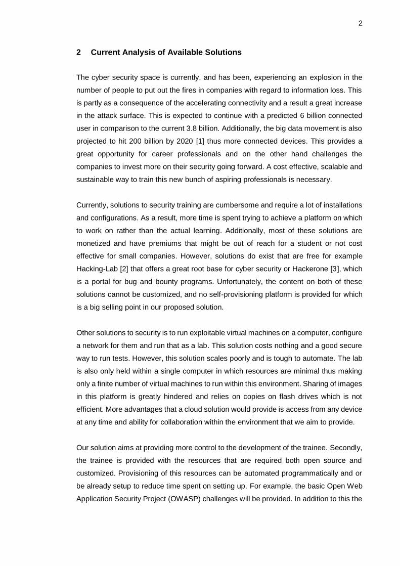
The NIST model offers a structure and conceptualizes on what constitutes a cloud.
Figure 2 shows an interpretation of this model. From this essential composition stems
the main building blocks of our project and what we are leveraging on to drive the project.
Figure 2. NIST cloud definition framework.
The cloud thrives on the concept of it being available anywhere, anytime and from a
heterogeneous platform of devices, be it thin or thick clients. The resources to be
accessed: memory, processing power, storage, network bandwidth, are pooled together
to provide automatic and on-demand services on a multi tenancy model. The cloud
resources are elastically provisioned and released in accordance to the consumer’s

6
requirements. Additionally, cloud systems have a metering capability that ensures proper
utilization of resources, pricing and added optimizations for efficient use [6].
Cloud computing can also be viewed on the concept of what kind of services it offers to
the consumer. Software as a service (SaaS), provides the consumer with the ability to
access applications over the network. An example of this service is Gmail and
GoogleDocs. This takes away from the consumer the problem of compatibility of software
with different operating systems. Furthermore, it saves the cost of; buying the software,
installation and maintenance costs, together with cheaper rates of cost on use basis. The
service provider handles the underlying implementation.
Second service is one provided as a platform, PaaS. The provider in this case provides
an environment on which a consumer can be creative. The is provided for with
development, design, testing, deployment hosting, storage, versioning and a multitude
of other service as long as the provider supports the languages, libraries and tools.
Google app engine, Heroku, AWS Elastic Beanstalk are examples of a PaaS. The
platform offers all the essential characteristics of any cloud model. However, there has
been a major challenge on the interoperability in porting applications to different
platforms.
Final service model is Infrastructure as a service (IaaS). IaaS provides the customer with
fundamental computing resources. Examples of this include, Processing power, storage,
network, etc. [6]. In this case the consumer has the total control of the resources and
software that runs within. It is the duty of the consumer to configure and operate the
logical resources, with the provider left with the responsibility to maintain and host
physical components of the infrastructure. Examples of PaaS include Amazon EC2,
Rackspace, etc. [7]. Main selling points of IaaS it that it allows the consumer to scale up
or down any resource according to the use requirements and this is possible within
minutes of demand.
Cloud computing deployment models is a classification on ownership, size and how they
can be accessed as shown in table 1.

7
Table 1. Classification of cloud deployments
Private cloud Public cloud Community
cloud
Hybrid cloud
Ownership
Organization General public Community of consumers or third party provider.
Bind of private, public and/or community clouds
Size
Small to medium
Large Medium Small to large
Access
Departments. Usually on premises deployments.
Everybody. Accessible over the internet
Limited access. Requires authorization from community
Combination of rights according to the combination of implementation
Other variations of cloud deployment also exit. Virtual private clouds (VPC), is a hosted
cloud within a publically managed cloud. It is considered as a dedicated cloud to the
consumer. Second is an intercloud, which is a connection of two of more clouds. [8] [9].
4 OpenStack
OpenStack, which will be our main component in this thesis, as a software platform for
cloud computing. The main attraction to this software is that it’s free and open-source
under Apache version 2 licencing. Most deployments of the software are those as
infrastructure, where by virtual resources for example, routers, servers, containers are
provisioned for consumers. Developed from 2010, it currently boosts of more than 85,000
community members, 674 supporting companies in 180 countries during the writing of
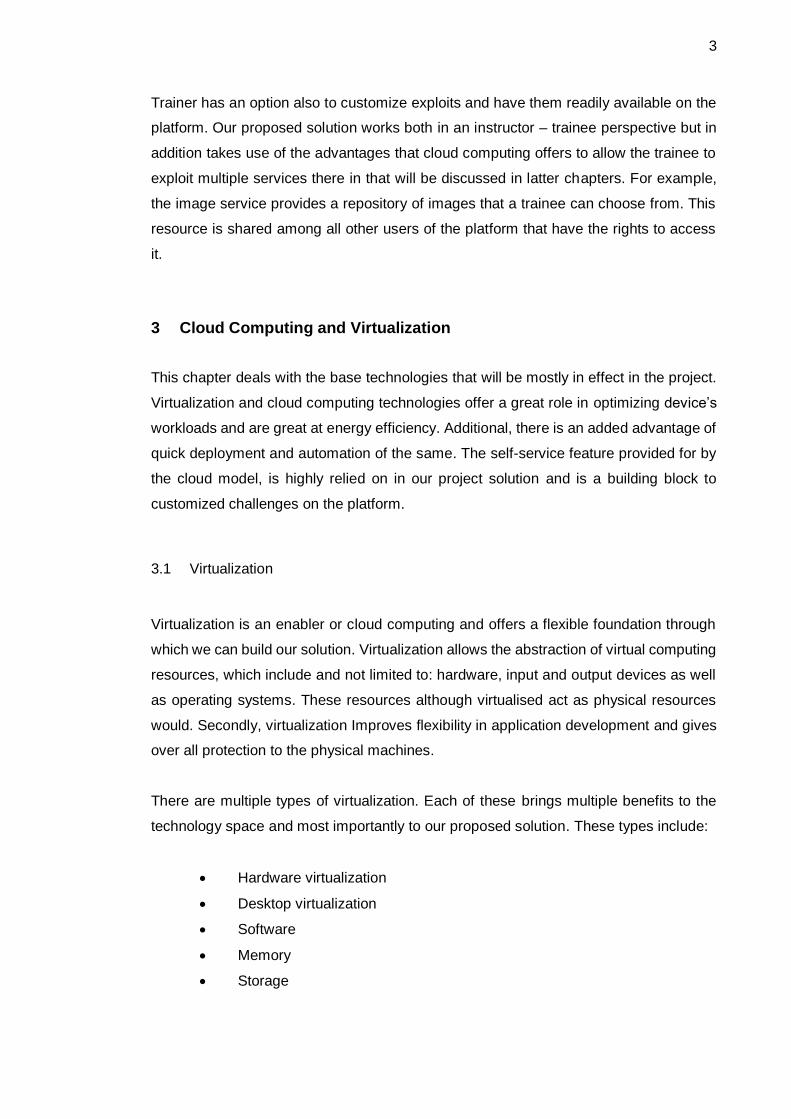
this thesis. Currently is run by the OpenStack Foundation [10]. A brief over- view on
what is OpenStack is shown in figure 3.
8
Figure 3. OpenStack overview. Reprinted from [10]
4.1 Physical Architecture
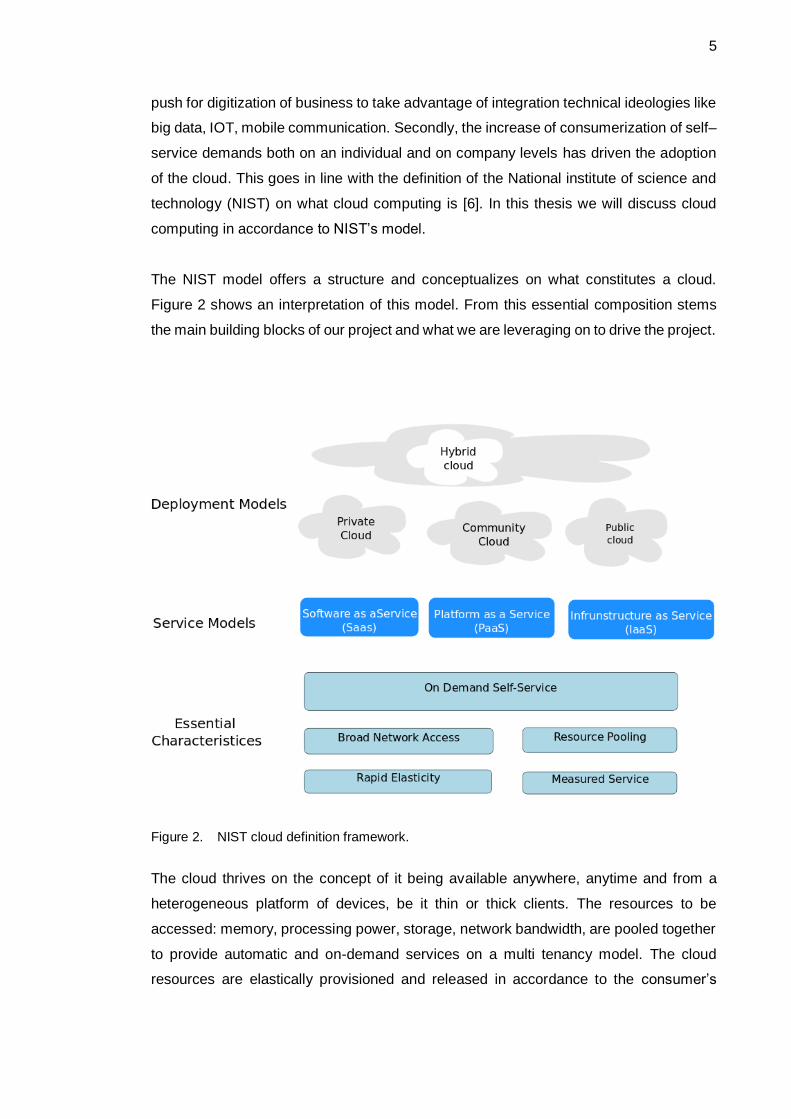
The project architecture during the writing of this thesis contains 5 nodes. These nodes
are shown in the figure 4 below. The values of the hardware are the minimum
requirements for a 5-node installation lab. However, a minimum 2-node lab is possible.
Figure 4. Project architecture nodes
The Controller node has implementations of identity services, manages all the other
nodes, orchestration and the main component is the dashboard. Second node, compute,
runs the hypervisor in this case KVM (kernel-based Virtual Machine). Additionally, it runs
Networking services and firewalling through security groups. Third is the Block storage.
Controller Node
•CPU: 1-2
•Storage: 100GB
•RAM: 8GB
•NIC: 2
Compute Node
•CPU: 2-4+
•Storage: 100 GB
•RAM: 8+ GB
•NIC: 2
Block Storage
•CPU: 1-2
•Storage: 100+ GB
•RAM: 4 GB
•NIC: 1
Object Node 1
•CPU: 1-2
•Storage: 100 + GB
•RAM: 4+ GB
•NIC: 1
Object Node 2
•CPU: 1-2
•Storage: 100+ GB
•RAM: 4+ GB
•NIC:1

9
This node contains the disks and shared file system. Lastly there is the object storage
for account, containers and object storage [11]. Additional hardware needed for the lab
is a network cables, network switch and a router for Internet connection.
The project nodes are an installation of Ubuntu server 16.04.
4.2 Conceptual Architecture
OpenStack is built on a modular architecture. This allows the users to implement what
they need. Additionally, there is a lot of documentation to allow for an own development.
This includes videos and text. The individual components are called OpenStack services.
In this project implementation, 9 services will be consolidated to make a platform on
which to run the cloud platform. These services are:
• Horizon
• Neutron
• Cinder
• Keystone
• Glance
• Nova
• Swift
• Heat
• Ceilometer
These services are individual projects. A table of the service, project and a brief
description of the services is contained in appendix 1.
The services above have been conceptualized to work together in this thesis to work like
the figure 5 below.
10
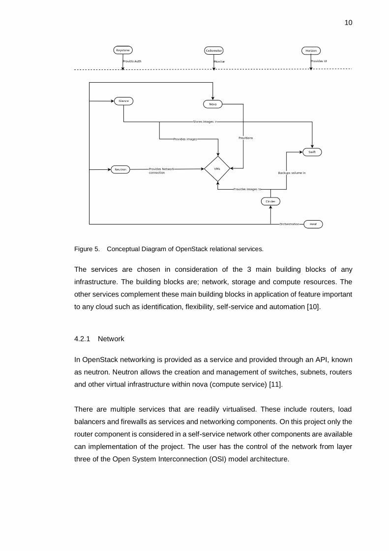
Figure 5. Conceptual Diagram of OpenStack relational services.
The services are chosen in consideration of the 3 main building blocks of any
infrastructure. The building blocks are; network, storage and compute resources. The
other services complement these main building blocks in application of feature important
to any cloud such as identification, flexibility, self-service and automation [10].
4.2.1 Network
In OpenStack networking is provided as a service and provided through an API, known
as neutron. Neutron allows the creation and management of switches, subnets, routers
and other virtual infrastructure within nova (compute service) [11].
There are multiple services that are readily virtualised. These include routers, load
balancers and firewalls as services and networking components. On this project only the
router component is considered in a self-service network other components are available
can implementation of the project. The user has the control of the network from layer
three of the Open System Interconnection (OSI) model architecture.
11
4.2.2 Storage
OpenStack provides multiple ways in which to store data. There is cinder, which
manages block storage. Second is swift which stores objects in a distributed and highly
available way. The objects are easily available over HTTP/HTTPS. Third is glance where
the images running the various operating systems will be stored. And lastly is nova.
Although considered mainly as a compute service, the operating systems instances are
stored here.
4.2.3 Compute
There are multiple projects that work on compute resources in OpenStack. The main one
is nova. This service requires other projects to work. The main requirements are,
• Keystone
• Glance
• Neutron
Other services can also be integrated into nova to allow improved storage and bare metal
compute service.
4.3 Logical Architecture
OpenStack is a combination of independent services working together. For these
services to work, they must authenticate to each other. This is accomplished through
Keystone service which provides users with tokens for authentication to services. Once
authenticated, these services communicate through application programing interfaces
(APIs) provided administration privileges are not required.
The services consist of a minimum of 1 API call. The services listen for requests, process
them and pass them to other services. For internal service communication, the states
are controller using Advanced Message Queuing Protocol (AMPQ) broker for example
RabbitMQ. These states are maintained in a database with options of using MSQL,
MariaDB or SQLite.
12
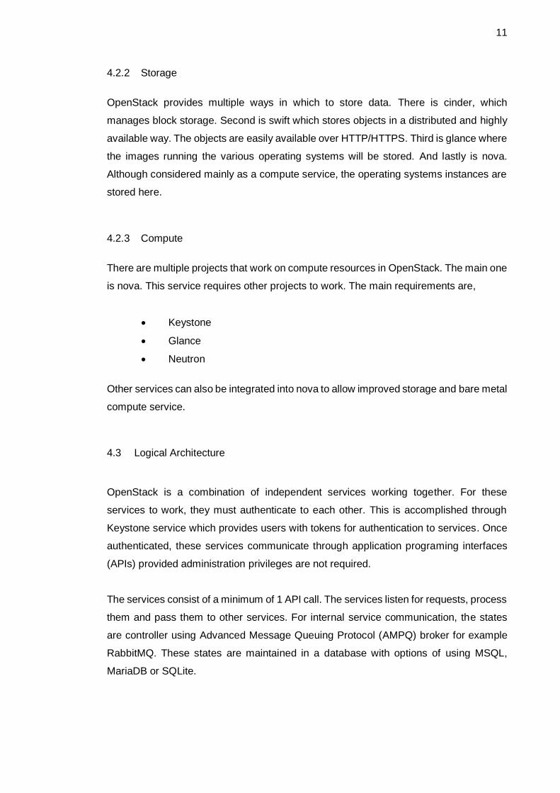
A user interface provided for by horizon, provides a portal through which users can
interact with OpenStack. This is over a browser. Other options include API calls from
browser plugins or curl (terminal interface that works over HTTP). All the services except
the identity service work the same. Example of how nova works; Nova is where the
hypervisor is maintained, thus the virtual machines. In Nova the virtual machines are
seen as server processes communicating within nova as remote procedure calls (RPC)
messages (an abstraction of top of the message queue). The user controls the processes
over a REST API with read and rights to a database and RPC messages to components
within Nova. Figure 6 shows the Nova architecture and how it works with other services.
Additionally it contains RPC messages done over oslo.messaging library.
Figure 6. Basic Nova deployment [13]
In appendix 2 shows the other services’ architectures. The conceptual idea is the same
in most of them but implemented to their functionality. The only difference is in the identity
service (Keystone).
13
5 OpenStack Cloud Development
The cloud development section provides information on designing and highlights the
concepts, cloud architecture and design requirements. Additionally, this section goes
through the deployment of the networking service.
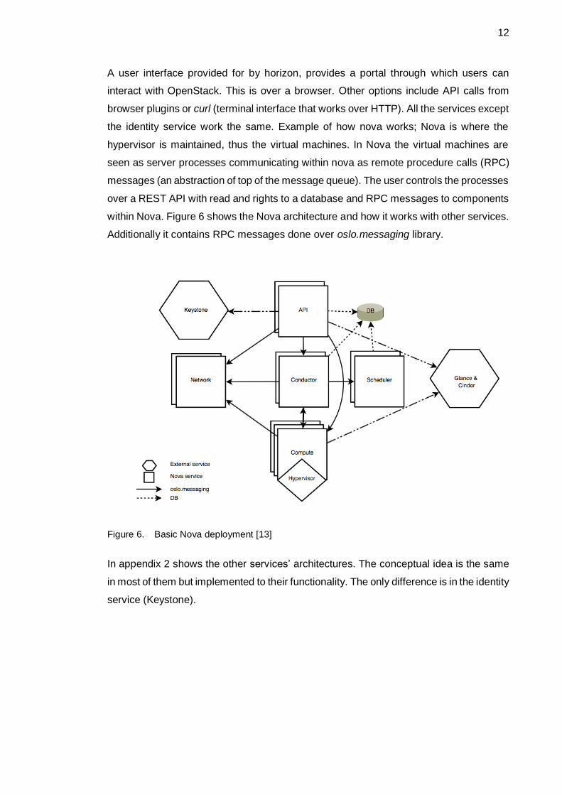
The architecture contains 5 nodes. On each node is an installation of Ubuntu server
16.04 with an openSSH server for secure remote communication to each node. The
network architecture and network addressing are as shown below in figure 7. The
addressing is spaced to allow expansion.
Figure 7. Project network layout.
Both the Provider and management networks contains private addresses. Despite this,
the provider network should be routable and have direct access to the Internet. However,
on a production network, this address should be publically available. The management

14
network separation is for security reasons. However, all the nodes require Internet
access for updates and time synchronization. This has been enabled through network
address translation (NAT).
A few base configurations needs to be setup to allow networking between the nodes. For
example, the time on all nodes should be the same to allow proper scheduling of process,
API calls. These nodes should be identifiable to each other. IP addresses could be used
to handle this but configuring naming resolution provides names that are easy to
remember.
5.1 Setting Up the Environment
Configure the interface and name resolution on all nodes. An example configuration is
shown below. The “INTERFACE_NAME” will vary. Edit /etc/network/interfaces file for
interfaces.
auto INTERFACE_NAME
iface INTERFACE_NAME inet manual
up ip link set dev $IFACE up
down ip link set dev $IFACE down
The /etc./hosts file for name resolution.
# controller
10.0.0.11 controller
# compute1
10.0.0.31 compute1
# block1
10.0.0.41 block1
# object1
10.0.0.51 object1
# object2
10.0.0.52 object2
Reboot the system to activate changes and verify the configurations.
5.2 Time Synchronization
The services should be properly synchronised among all nodes. The controller node has
been used as a reference for the other nodes. While the controller node acquires the

15
synchronization from ntp.org servers as seen in image 1 below. On the controller node,
install chrony and configure.
apt install chrony
Edit the /etc./chrony/chrony.conf file. Delete the unnecessary keys that describe other
servers and add the ones below if you live in Finland. Also allow the whole 10.0.0.0/24
network.
server 0.fi.pool.ntp.org iburst
server 1.fi.pool.ntp.org iburst
server 2.fi.pool.ntp.org iburst
server 3.fi.pool.ntp.org iburst
allow 10.0.0.0/24
Restart the service.
service chrony restart
Install chrony on all other nodes and allow them to reference the controller node.
server controller iburst
Restart the service and verify NTP synchronization. [14]
Image 1. Chronyc sources

16
Other initialization services that are important in the establishment of the platform are:
• OpenStack packages [15]
• SQL database [16]
• Message queue [17]
• Memcacheed [18]
The installation is also highlighted in the appendix 3.
5.3 Service Installation
All the OpenStack services are independent project built around the resource
components with each project aiming to virtualize a resource. The installation of all the
OpenStack services follows the same basic procedure. In essence the services are API’s
whose endpoints are attached to OpenStack. The installation manuals can be found in
OpenStack documentation for the major operating system ditributions. However, one
thing to note is the version of OpenStack preferred and the base operating system. Below
is the installation of one service, networking service “neutron” to provide a general idea
of installation processes and what modifications need to be added to allow
interoperability of software and API services. Documentation on other resources based
on version and operating system can be found on the organization website [19].
Neutron allows users to define networks through an API. It works with most main source
interface devices. Many plug-ins have been implemented to provide compatibility with
these devices. The networks created by this service allow other services to work. For
example, provides connectivity for instances in the compute node. The main components
of the networking service are:
• Neutron-server
• OpenStack Networking plug-ins and agents
• Messaging queue
5.3.1 Prerequisites
On the controller node, create database, service credentials and API endpoints. This is
additionally done for all the other major services.
17
mysql -u root –p
CREATE DATABASE neutron;
GRANT ALL PRIVILEGES ON neutron.* TO 'neutron'@'localhost' \
IDENTIFIED BY 'NEUTRON_DBPASS';
GRANT ALL PRIVILEGES ON neutron.* TO 'neutron'@'%' \
IDENTIFIED BY 'NEUTRON_DBPASS';
Source admin credentials for admin access to the OpenStack API. These are created
when developing the identity service (Keystone). Keystone uses domains, projects,
users and roles for authentication and authorization. Two scripts have been created
”admin-openrc” for administration and ”demo-openrc” for basic users. Scripts can be
found in the appendix 4.
. admin-openrc
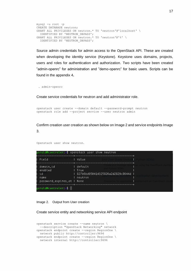
Create service credentials for neutron and add administrator role.
openstack user create --domain default --password-prompt neutron
openstack role add --project service --user neutron admin
Confirm creation user creation as shown below on Image 2 and service endpoints Image
3.
Openstack user show neutron.
Image 2. Output from User creation
Create service entity and networking service API endpoint
openstack service create --name neutron \
--description "OpenStack Networking" network
openstack endpoint create --region RegionOne \
network public http://controller:9696
openstack endpoint create --region RegionOne \
network internal http://controller:9696

18
openstack endpoint create --region RegionOne \
network admin http://controller:9696
Image 3. Service endpoints
5.3.2 Self-Service Networks
Install and configure the Networking components on the controller node. A self-service
network was chosen to allow layer 3 services to attach instances to different self-service
networks.
apt install neutron-server neutron-plugin-ml2 neutron-linuxbridge-agent
neutron-l3-agent neutron-dhcp-agent neutron-metadata-agent
Configure server components. Edit the /etc./neutron/neutron.conf file. Under each
section add the sections that might be missing in the file.
[database]
connection = mysql+pymysql://neutron:NEUTRON_DBPASS@controller/neutron
[DEFAULT]
core_plugin = ml2
service_plugins = router
allow_overlapping_ips = True
transport_url = rabbit://openstack:RABBIT_PASS@controller
auth_strategy = keystone
notify_nova_on_port_status_changes = True
notify_nova_on_port_data_changes = True
[keystone_authtoken]
auth_uri = http://controller:5000
auth_url = http://controller:35357
memcached_servers = controller:11211
auth_type = password
project_domain_name = Default
user_domain_name = Default
project_name = service
username = neutron
password = NEUTRON_PASS
[nova]
auth_url = http://controller:35357
auth_type = password
project_domain_name = Default
user_domain_name = Default
19
region_name = RegionOne
project_name = service
username = nova
password = NOVA_PASS
Configure the modular layer 2 plug-in. Edit the /etc/neutron/plugins/ml2/ml2_conf.ini file.
Under each section add the following content.
[ml2]
type_drivers = flat,vlan,vxlan
tenant_network_types = vxlan
mechanism_drivers = linuxbridge,l2population
extension_drivers = port_security
[ml2_type_flat]
flat_networks = provider
[ml2_type_vxlan]
vni_ranges = 1:1000
[securitygroup]
enable_ipset = True
Configure the Linux bridge agent. This allows layer 2 bridging and switching of virtual
networks. Additionally, the agent handles security groups. Edit and modify sections in
the /etc/neutron/plugins/ml2/linuxbridge_agent.ini file. If the sections are missing add
them.
[linux_bridge]
physical_interface_mappings = provider:PROVIDER_INTERFACE_NAME
Note: PROVIDER_INTERFACE_NAME = the controllers public interfaces.
[vxlan]
enable_vxlan = True
local_ip = OVERLAY_INTERFACE_IP_ADDRESS
l2_population = True
Note: OVERLAY_INTERFACE_IP_ADDRESS = the controllers Management interface.
[securitygroup]
enable_security_group = True
firewall_driver = neutron.agent.linux.iptables_firewall.IptablesFirewallDriver
Configure layer 3 agent. Edit the /etc/neutron/l3_agent.ini file. Modify the necessary
sections as shown below.
[DEFAULT]
interface_driver = neutron.agent.linux.interface.BridgeInterfaceDriver
20
Configure the DHCP agent. This provides DHCP services for the virtual networks. Edit
the /etc/neutron/dhcp_agent.ini file.
[DEFAULT]
interface_driver = neutron.agent.linux.interface.BridgeInterfaceDriver
dhcp_driver = neutron.agent.linux.dhcp.Dnsmasq
enable_isolated_metadata = True
5.3.3 Configure Compute service to Work with Networking Service
On the controller node configure the metadata agent, which provides credentials to the
instances. Edit the /etc/neutron/metadata_agent.ini file on the default section.
[DEFAULT]
nova_metadata_ip = controller
metadata_proxy_shared_secret = METADATA_SECRET
For the compute service and networking service to work together they need to be
configured as shown below. Edit the /etc/nova/nova.conf file and modify the neutron
section which offers computing services.
[neutron]
url = http://controller:9696
auth_url = http://controller:35357
auth_type = password
project_domain_name = Default
user_domain_name = Default
region_name = RegionOne
project_name = service
username = neutron
password = NEUTRON_PASS
service_metadata_proxy = True
metadata_proxy_shared_secret = METADATA_SECRET
To finalize the installation, populate the database, restart the compute API service and
restart networking services.
su -s /bin/sh -c "neutron-db-manage --config-file /etc/neutron/neutron.conf \
--config-file /etc/neutron/plugins/ml2/ml2_conf.ini upgrade head" neutron
service nova-api restart
service neutron-server restart
service neutron-linuxbridge-agent restart
service neutron-dhcp-agent restart
service neutron-metadata-agent restart
service neutron-l3-agent restart

21
Verify the configured agents are working image 4.
Image 4. Test network agents functionality
The extensions that are have been launched from the neutron-server can also be used
to verify successful installation. These extensions show the capabilities of the neutron
service.

22
6 The Lab
Having the platform up is one of the first steps in the making up the labs. The next
process is the design of the labs on which the trainees will practice. The main
components available to build on are shown below
• Compute resources.
• Network: A complete network of vulnerable machines and services can be setup.
• Routers to create complex networks.
• Vulnerable images, public or custom made, contained in glance.
• Templates to orchestrate lab creation.
• Storage containers to store files containing instructions.
• Metering for lab administrator.
Several options exist on how a trainee or instructor can setup the labs, each with a
different level of complexity. The options are:
• The trainee or instructor will setup the servers in a network. This is more of a do it yourself lab creation.
• The instances are already setup in a network and the student only needs to connect to a host and start working.
• The instructor or trainee has a Heat template from which a stack can be setup.
6.1 Setting up Instances in a Network (Options 1)
In OpenStack, servers are referred to as instances. The steps to setting up an instance
are shown in the subsequent subtopics. One thing of note is that the procedure if for
clients using the horizon user interface. Similar configurations can be done on the
OpenStack console. However, for ease of use, the writer of this thesis has decided to
use the graphical representation of the procedures. The figure below is a snippet of the
view on that interface.
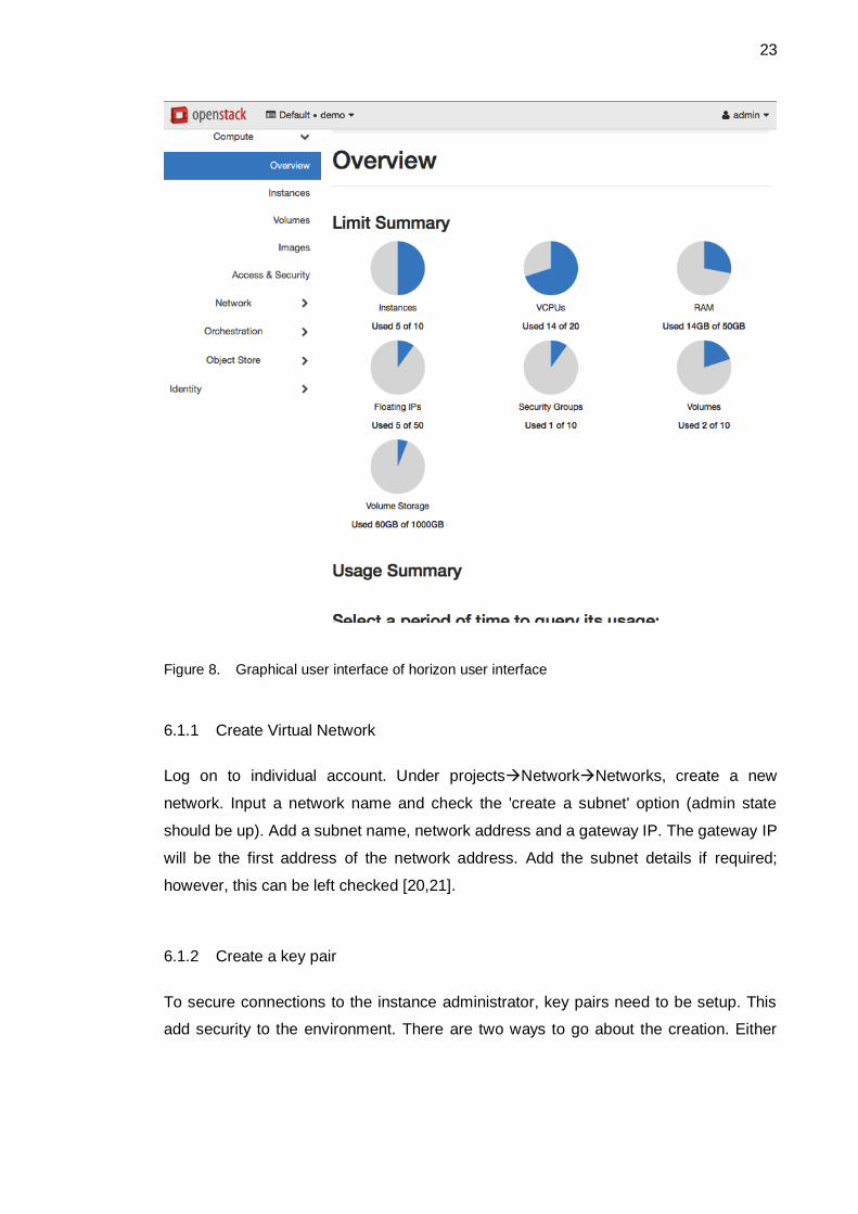
23
Figure 8. Graphical user interface of horizon user interface
6.1.1 Create Virtual Network
Log on to individual account. Under projects→Network→Networks, create a new
network. Input a network name and check the 'create a subnet' option (admin state
should be up). Add a subnet name, network address and a gateway IP. The gateway IP
will be the first address of the network address. Add the subnet details if required;
however, this can be left checked [20,21].
6.1.2 Create a key pair
To secure connections to the instance administrator, key pairs need to be setup. This
add security to the environment. There are two ways to go about the creation. Either
24
from the horizon dashboard a key can be created, or a key can be imported into the
environment.
To add a key into to the project, go to compute→Key Pairs→Create Key Pair. Add a
name for the keys to create the pairs. Follow the prompt to finish the addition of the key.
to import a key, on the compute→Key Pairs page, click import key and follow the prompt.
In this case, generation of a key is done from the personal computer. Multiple tutorials
exist on how to do this [21]
6.1.3 Create an Instance
This is where the servers will be setup. The platform already contains Images of
vulnerable servers on which the trainee will be working with. The instructions to this are
shown on the reference document [22].
A few things to note about the creation are that. The source of the Image to add on the
instance will be one of the vulnerable operating systems from the image service.
Secondly, the flavour can be chosen from the available options and considerations
should be made on what resources are needed for the server. The minimum flavour is
adequate in most scenarios. Additionally, the network on which the instance is connected
should be the one that was created in the step above and so should be the key pairs.
In addition to the Instance of the vulnerable server, An Image of kali Linux has been
provided to work as a machine from which the trainee can do penetration testing from.
This completely isolates the hacking to the infrastructure created. From this Kali Linux
instance, an individual can start their training process. How to connect to this Kali Linux
instance is shown in the reference document [22]. In addition to this a virtual private
network (VPN) can be set up from the network created to an individual machine.
However, this has been left out to limit the scope of the thesis.
6.2 Already Setup labs (Option 2)
The other option is to have the labs already setup. In this scenario, an instructor will
setup a lab for the trainee. The networks, the instances will be provided as well as the
instructions to the lab as object files. All what the trainee has to do is add own key pairs

25
for the Kali Linux instance and the student can get to work. The instructions on how to
connect to the network using the Kali machine that would already exist are shown in the
Instructions in reference [23].
In addition to the setup above, there is an option in which the instructor would only need
to setup a vulnerable server or network and provide the trainee with IP address to it.
From this IP, the student would have the task of trying to access the system. No key
pairing, no Kali distribution would be needed. Additionally, the student wouldn’t need to
enrol to the platform. This would be kept private to only the administrator. The benefit
that this would provide is to the instructor cause help easily provide individual machines
to all the trainees. This can be done from HEAT templates. It is recommended however
in this case that the trainee uses a virtualized testing environment to limit any effect of
the host from vulnerable distribution in the testing environment.
6.3 Template Labs (Option 3)
This option allows the instructor or trainee to quickly deploy any infrastructure with own
customization. For the instructor it provides ability to deploy multiple customized
instances for the students quickly and at scale. For students having the templates allows
quick deployments for quick experiments. This option can be used in any scenarios that
the options 1 and 2 provides. Below is an example of a basic heat template.
heat_template_version: 2015-10-15
description: Launch a basic instance with CirrOS image using the
``tiny`` flavor, ``sshKey1`` key, and one network.
parameters:
NetID:
type: string
description: Network ID to use for the instance.
resources:
server:
type: OS::Nova::Server
properties:
image: cirros
flavor: tiny
key_name: sshKEY1
networks:
- network: { get_param: NetID }
outputs:
instance_name:
description: Name of the instance.
value: { get_attr: [ server, name ] }
instance_ip:
26
description: IP address of the instance.
value: { get_attr: [ server, first_address ] }
Heat templates basically describe the infrastructure as code that is understandable by
humans. It describes relationship of resources for example what block storage is
connected to which server. It’s used to managing the infrastructure in addition to
functionalities such as auto scaling, high availability and use of nested stacks. One great
advantage of heat is that it integrates easily to configuration management tools like
Puppet and Ansible which brings additional control to anything deployed by the heat
templates.
6.4 Metering
Information on metering is a great way to keep track of what is happening on the platform
but also could be used for assessment. In enterprise installation of cloud platforms, the
metering is used to bill the customer on the resources that they have used. In the lab
scenario, the metering could be used in cases where an assessment needs to be done
in addition to maintenance.
7 How Lab and OpenStack Integrate
OpenStack provides for the creation of a platform that brings together services, which
offers infrastructure. The resources herein can be provisioned by either the instructor or
the student offering personalised control. The combination of what OpenStack provides,
the problem that it aims to solve, and the implementation is what constitutes the virtualise
hacking lab. For the student it’s a playing field where they can sharpen their skills and
also individually encourage self-learning by including own projects into the platform. For
the instructor its where to go to easily provision resources and setup labs. The setup can
be used either in a learning environment for example universities, security companies or
any group working with security.
For an installation in a single campus, the instructor would be the administrator. In his
account he would have the abilities to:
• Manage identities
27
(a) Projects
(b) Users
(c) Groups
(d) Roles
• Administer the system
(a) All resources (memory, networks, host aggregates, volumes)
(b) Add and manage flavours
(c) Manage images, instances, routers, floating IPs
• Do all that users/trainee can do
On the other hand, the trainees should be able to:
• Create and manage resources (instances, volumes, images, stacks, networks, routers)
• Add containers and objects
• Manage access and security to their instances
All these is dependent on the option of how the instructor has implemented his lab and what levels of access the administrator is willing to provide
7.1 Developing the Labs
Apart from the management of the resources and what the developed environment
provides, the lab is also dependant on the quality of vulnerability that it provides. Security
is always quickly evolving, and good images for the instances are required. To develop
custom images is not a simple task and some work needs to go into it. However, there
are multiple places on the internet that provides vulnerable images that can run in the
created platform.
A good starting place for where to get free images would be form the Open Web
Application Security Project (OWASP) organization. OWASP have multiple projects that
have insecure web application that are designed for teaching web security. A good
example is their WebGoat project, which is targeted at trainees with medium skill level
[23]. Other more challenging projects would be from sites like Pentesterlab.com that
provide images and instructional use of how to develop the hacks. However, unlike the
OWASP projects, there is a price to pay for more advanced instructions and the images
that come with them. Apart from the web sources there are multiple books, which an
28
instructor could shape their course around. The “Hands-On Information Security Lab
Manual” by Michael E. Whitman, Herbert J. Mattord and Andrew Green provide a
comprehensive consultative manual for instructors to complement any other resources
they may be using. The book is also a good introductory level book to different
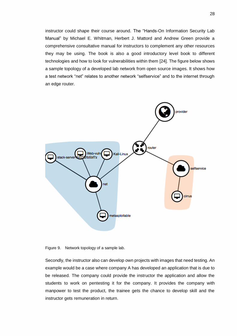
technologies and how to look for vulnerabilities within them [24]. The figure below shows
a sample topology of a developed lab network from open source images. It shows how
a test network “net” relates to another network “selfservice” and to the internet through
an edge router.
Figure 9. Network topology of a sample lab.
Secondly, the instructor also can develop own projects with images that need testing. An
example would be a case where company A has developed an application that is due to
be released. The company could provide the instructor the application and allow the
students to work on pentesting it for the company. It provides the company with
manpower to test the product, the trainee gets the chance to develop skill and the
instructor gets remuneration in return.
29
The student also has a chance to develop own lab as per option 1 in chapter 6. In this
way they are not limited to what the instructor provides or what exists on the glance
image storage. They can also just follow instructor set projects. For limited users they
can be provided with an IP address through which they can try to exploit the services or
applications.
7.2 Documentation
OpenStack Swift offers a service to store and retrieve objects within the cloud platform.
The storage is optimized for durability, availability and concurrency which is handled by
OpenStack software. In the current environment its build to replicate to two different disks
within one of the nodes. The data stored is unstructured can grow limitlessly.
In our scenario, documentation can be shared through this service. Objects which are
files in essence can either be private or public. The files are available over HTTP or can
be downloaded if connected to the environment. Other options available is to create
containers for organizational purposes and upload files to the containers.
This form of storage is cost effective and scalable. It provides distributed storage which
is easily accessible from an API. This means the data can be in cooperated directly into
applications. For example, an instructor could have a website from which he provides his
projects to students. API calls to swift could retrieve the documentation (files in this case
objects) to the public site which could also be hosted on the cloud environment [25].
7.3 Manage Flavors, Floating IP and Defaults
The administrator of the cloud needs multiple ways with which to control what users do
on the platform and to what level of resources users need. Without regulation, the cloud
would be at all times saturated which results in lower the service levels of the complete
platform. To manage the resource there are flavors and default resource limits. To allow
access of this resources on the internet the floating IPs are used.
Flavors define the compute, memory and storage capacity of an instance. The
administrator can create, edit and delete them. Flavors will regulate the resources that a
30
non-administrative user can access. For example, in an instructor trainee scenario for a
student using deployment option 1, the administrator can setup just one flavor for all
instances/servers. This limits misuse of resources by trainee [26].
Other resources for example object storage or resources can be controlled using
defaults. This is found under Admin tab for an administrative user. Under ‘Defaults’,
controls on how large image are allowed to be, the volume sizes, key pairs, server groups
and many more setting can be achieved. Most of the virtualised resources that need to
be controlled under ‘Defaults’ are those that are above the scope of an instance.
Floating IPs are publically accessible static addresses that can be assigned to an
instance. The IPs are mapped to the network IPs of instances created in chapter 6. Basic
users have the ability to assign an IP to an instance, but the administrator controls which
ones are available to the users. Administrator can also disassociate and release the IPs.
In relation to our recurring scenario, the administrator could set a floating IP to a VPN
server from which a trainee could connect to a complete vulnerable network of servers
(service option 2). To limit access the admin would only need to disassociate the floating
IP [27,28].
8 Conclusion
The thesis looks at how to create a platform to run hacking practises without the hustle
of setting up the infrastructure of resources. Secondly it provides ability to provision
customised configurations for complex hacks with freedoms to both the student and
instructor. The ability to control the environment is granular and can be controlled in 3
major levels to correspond with the cloud service levels. One would be as infrastructure
where the instructor or student has the ability to build own solutions. Secondly as a
platform where instructor provides infrastructure as code from which students can create
environments. Lastly, as a service where environment is configured and student can run
tests directly.
As at the per the time of writing of this thesis, a couple of improvements would be
necessary to improve the functionality and scalability platform. These improvements are
mainly in network and hardware. In networks, there would be a need to separate the
production traffic and management traffic which would require a dedicated additional

31
interface. This would be in line with networking standard on production networks and in
general would improve security in addition to all benefits of network separation. On the
hardware level, the components for this platform built where from sourced products and
recycled parts. To improve operation, use of standardized networking equipment would
be advised. Despite these shortfalls, a lean platform could in retrospect be created with
just composition of two modes, the controller and compute node. For individuals who
would want to implement this sought of project, two nodes would be able to maintain a
good level system to allow most simplified cyber hacks.
More work does need to be done on how to setup the lab with more automation. Use of
more tools like puppet and chef to allow automation of resources does benefit both the
administrator of the platform and those working on it. In addition to this, the creation of
more content to work within this platform is something that needs more work and
commitment to developing individualised exploitable components together with working
instructions. Security is a sector that is always moving and at a high speed. Development
of the content is paramount on commitment of the administrators the platform and level
of skill. The security of the platform should high priority.
The platform is a good start for a place to hold CFT (capture the flag) competitions and
can host such if need be. Additionally, it is a place just to host images where and
solutions to these vulnerabilities can be shared from the public option of object storage.
Volume storage has been added to also incorporate in later versions databases which
are components in cyber security that would need to be tested.

32
References
1 Harjavec Group, Steve Morgan “2017 cyber crime report,” [Online]. Available: https://cybersecurityventures.com/2015-wp/wp-content/uploads/2017/10/2017-Cybercrime-Report.pdf [Date accessed: 12.12.2017]
2 OWASP ”OWASAP Hacking Lab,” [online]. Available: https://www.owasp.org/index.php/OWASP_Hacking_Lab [Date accessed: 14.12.2017]
3 Hackerone ” WHAT IS HACKER101?,” Available: https://www.hackerone.com/hacker101 [Date accessed: 22.12.2017]
4 Bhanu P Tholeti ”Hypervisor, virtualization and the cloud,” [Online]. Available: https://www.ibm.com/developerworks/cloud/library/cl-hypervisorcompare/ [Date accessed: 12.12.2017]
5 Bond J. “The Enterprise Cloud,” Sebastopol, CA: O’Reilliys Media; 2015
6 Peter M and Tomothy G. ”The NIST Definition of Cloud Computing,” [Online] Available: http://nvlpubs.nist.gov/nistpubs/Legacy/SP/nistspecialpublication800-145.pdf [Date accessed: 12.12.2017]
7 AWS. ”Amazon EC2” [online]. Available: https://aws.amazon.com/ec2/ [Date
accessed: 18.01.2018]
8 Thomas E., Zaigham M. and Ricardo P. ”Cloud Computing: Concepts,
Technology & Architecture ” ; CA: Arcitura Education Inc. ; 2013
9 Arcitura Education Incorporated- ”Cloud deployment Models” [Online]. Available: http://whatiscloud.com/cloud_deployment_models/index [Date accessed: 12.01.2017]
10 Openstack “What is openStack” [Online]. Available: https://www.openstack.org/software/ [Date accessed: 07.01.2018]
11 Openstack Documentation “Networking services” [Online] Available: https://docs.openstack.org/security-guide/networking/services.html [Date accessed: 05.01.2018]
12 Openstack Documentation “OpenStack Documentation” [Online]. Available: https://docs.openstack.org/newton/install-guide-ubuntu/overview.html [Date accessed: 12.01.2017]
33
13 Openstack Documentation “Nova system architecture” [Online]. Available: https://docs.openstack.org/nova/latest/user/architecture.html [Date accessed: 21.12.2017]
14 Openstack Documentation “Network Time Protocol (NTP)” [Online]. Available: https://docs.openstack.org/newton/install-guide-ubuntu/environment-ntp.html [Date accessed: 12.03.2018]
15 OpenStack Documentation “OpenStack packages [Online]. Available: https://docs.openstack.org/newton/install-guide-ubuntu/environment-packages.html [Date accessed: 12.03.2018]
16 OpenStack Documentation “SQL Database” [Online]. Available: https://docs.openstack.org/newton/install-guide-ubuntu/environment-sql-database.html [Date accessed: 13.02.2018]
17 OpenStack Documentation “Message queue” [Online]. Available: https://docs.openstack.org/newton/install-guide-ubuntu/environment-messaging.html [Date accessed: 13.02.2018]
18 OpenStack Documentation “Memcached” [Online]. Available: https://docs.openstack.org/newton/install-guide-ubuntu/environment-memcached.html [Date accessed: 13.02.2018]
19 OpenStack Documentation “Documentation for Newton (October 2016)” [Online]. Available: https://docs.openstack.org/newton/ [Date accessed: 13.02.2018]
20 OpenStack Documentation “OpenStack Networking” [Online]. Available: https://docs.openstack.org/newton/networking-guide/intro-os-networking.html [Date accessed: 13.02.2018]
21 OpenStack Documentation - Horizon 13.0.0 “Configure access and security for instances” [Online]. Available: https://docs.openstack.org/horizon/latest/user/configure-access-and-security-for-instances.html [Date accessed: 13.02.2018]
22 Horizon 13.0.0 “Launch and manage instances” [Online]. Available: https://docs.openstack.org/horizon/latest/user/launch-instances.html [Date accessed: 13.02.2018]
23 OWASP Vulnerable Web Application Directory Project “VMs which contain multiple vulnerable applications” [Online]. Available: https://www.owasp.org/index.php/OWASP_Vulnerable_Web_Applications_Directory_Project#tab=Virtual_Machines_or_ISOs [Date accessed: 13.02.2018]
24 Michael E. Whitman, Herbert J. Mattord and Andrew Green “Hands-On Information Security Lab Manual”CA: O’Reilliys Media; 2011
34
25 Swift “Object Storage service overview” [Online]. Available: https://docs.openstack.org/project-install-guide/object-storage/newton/get_started.html [Date accessed: 13.02.2018]
26 Horizon 13.0.0 “Manage Flavors” [Online]. Available: https://docs.openstack.org/horizon/latest/admin/manage-flavors.html [Date accessed: 13.03.2018]
27 OpenStack Documentation “Manage IP addresses” [Online]. Available: https://docs.openstack.org/ocata/user-guide/cli-manage-ip-addresses.html [Date accessed: 13.03.2018]
28 Red Hat Enterprise Linux OpenStack Platform “Chapter 19. Adding Floating IP Addresses” [Online]. Available: https://access.redhat.com/documentation/en-US/Red_Hat_Enterprise_Linux_OpenStack_Platform/2/html/Getting_Started_Guide/exercise-floating-ip.html [Date accessed: 13.04.2018]

Appendix 1
1
OpenStack services
Service Project name
Description
Dashboard Horizon Provides a web-based self-service portal to interact with underlying OpenStack services, such as launching an instance, assigning IP addresses and configuring access controls.
Compute Nova Manages the lifecycle of compute instances in an OpenStack environment. Responsibilities include spawning, scheduling and decommissioning of virtual machines on demand.
Networking Neutron
Enables Network-Connectivity-as-a-Service for other OpenStack services, such as OpenStack Compute. Provides an API for users to define networks and the attachments into them. Has a pluggable architecture that supports many popular networking vendors and technologies.
Storage
Object Storage
Swift
Stores and retrieves arbitrary unstructured data objects via a RESTful, HTTP based API. It is highly fault tolerant with its data replication and scale-out architecture. Its implementation is not like a file server with mountable directories. In this case, it writes objects and files to multiple drives, ensuring the data is replicated across a server cluster.
Block Storage
Cinder Provides persistent block storage to running instances. Its pluggable driver architecture facilitates the creation and management of block storage devices.
Shared services
Identity service
Keystone Provides an authentication and authorization service for other OpenStack services. Provides a catalog of endpoints for all OpenStack services.
Image service
Glance Stores and retrieves virtual machine disk images. OpenStack Compute makes use of this during instance provisioning.
Telemetry Ceilometer Monitors and meters the OpenStack cloud for billing, benchmarking, scalability, and statistical purposes.
Higher-level services
Orchestration Heat
Orchestrates multiple composite cloud applications by using either the native HOT template format or the AWS CloudFormation template format, through both an OpenStack-native REST API and a CloudFormation-compatible Query API.
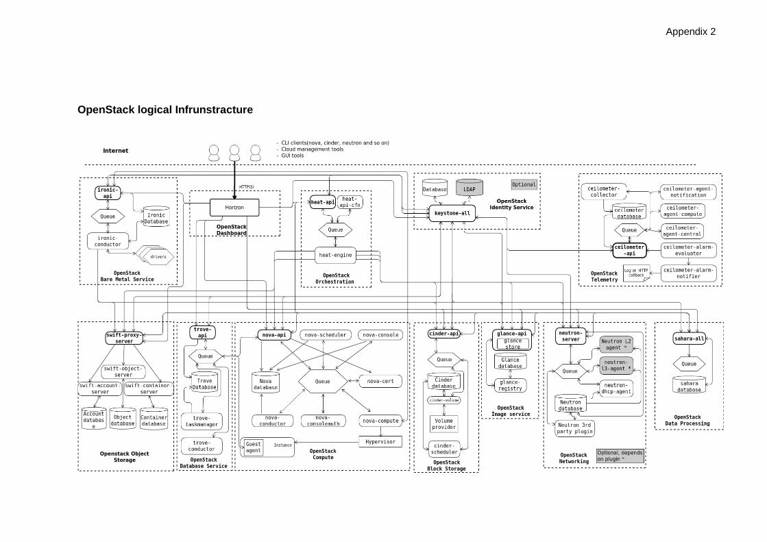
Appendix 2
OpenStack logical Infrunstracture

Appendix 3
OpenStack Packages
Install Openstack packages on all the nodes.
apt install software-properties-common
add-apt-repository cloud-archive:newton
apt update && apt dist-upgrade
apt install python-openstackclient
SQL Database
Install database and configure components on the controller node.
apt install mariadb-server python-pymysql
Create and edit /etc/mysql/mariadb.conf.d/99-openstack.cnf. Create a [mysqld]
section with a bind address to controller.
[mysqld]
bind-address = 10.0.0.11
default-storage-engine = innodb
innodb_file_per_table
max_connections = 4096
collation-server = utf8_general_ci
character-set-server = utf8
Restart service and secure the database with mysql_secure_installation installation
script.
mysql_secure_installation
Message Queue
Operations in OpenStack are controller using a message queue. In this Project
RabbitMQ will be used. It will run on the controller node.
Install component, add Openstack user and give read write permissions
apt install rabbitmq-server
rabbitmqctl add_user openstack RABBIT_PASS
rabbitmqctl set_permissions openstack ".*" ".*" ".*"
Appendix 3
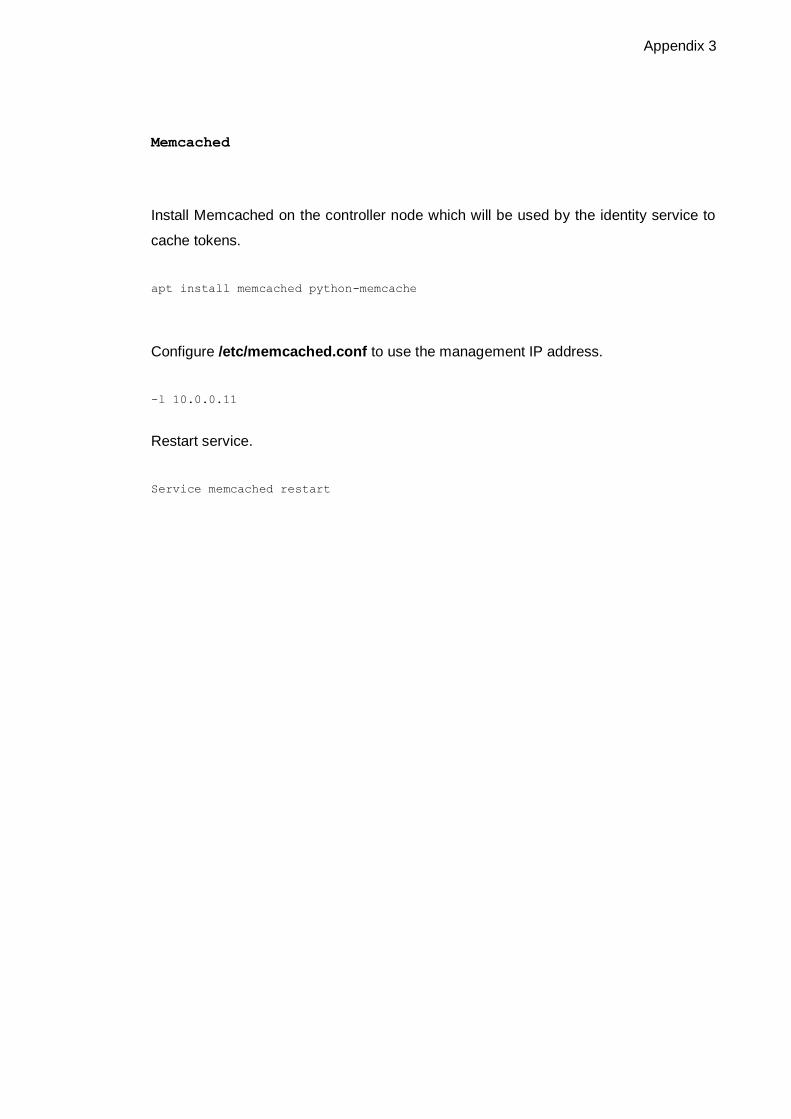
Memcached
Install Memcached on the controller node which will be used by the identity service to
cache tokens.
apt install memcached python-memcache
Configure /etc/memcached.conf to use the management IP address.
-l 10.0.0.11
Restart service.
Service memcached restart

Appendix 4
Scripts in Keystone service for authorization
admin-openrc
export OS_PROJECT_DOMAIN_NAME=Default
export OS_USER_DOMAIN_NAME=Default
export OS_PROJECT_NAME=admin
export OS_USERNAME=admin
export OS_PASSWORD=ADMIN_PASS
export OS_AUTH_URL=http://controller:35357/v3
export OS_IDENTITY_API_VERSION=3
export OS_IMAGE_API_VERSION=2
demo-openrc
export OS_PROJECT_DOMAIN_NAME=Default
export OS_USER_DOMAIN_NAME=Default
export OS_PROJECT_NAME=demo
export OS_USERNAME=demo
export OS_PASSWORD=DEMO_PASS
export OS_AUTH_URL=http://controller:5000/v3
export OS_IDENTITY_API_VERSION=3
export OS_IMAGE_API_VERSION=2

Appendix 5
Launch an instance
Log in to the dashboard.
Select the appropriate project from the drop-down menu at the top left.
On the Project tab, open the Compute tab and click Instances category.
The dashboard shows the instances with its name, its private and floating IP addresses,
size, status, task, power state, and so on.
Click Launch Instance.
In the Launch Instance dialog box, specify the following values:
Details
Instance Name: Assign a name to the virtual machine.
Description: You can assign a brief description of the virtual machine.
Availability Zone: By default, this value is set to the availability zone given by the cloud
provider. (for example, nova).
Count: To launch multiple instances, enter a value greater than 1. The default is 1.
Source tab
Instance Boot Source: Your options are:
Boot from image: If you choose this option, a new field for Image Name displays. You
can select the image from the list.
Boot from snapshot: If you choose this option, a new field for Instance
Snapshot displays. You can select the snapshot from the list.
Boot from volume: If you choose this option, a new field for Volume displays. You can
select the volume from the list.

Appendix 5
Boot from image (creates a new volume): With this option, you can boot from an image
and create a volume by entering the Device Size and Device Name for your volume.
Click the Delete Volume on Instance Delete option to delete the volume on deleting the
instance.
Boot from volume snapshot (creates a new volume): Using this option, you can boot from
a volume snapshot and create a new volume by choosing Volume Snapshot from a list
and adding a Device Name for your volume. Click the Delete Volume on Instance
Delete option to delete the volume on deleting the instance.
Image Name
This field changes based on your previous selection. If you have chosen to launch an
instance using an image, the Image Name field displays. Select the image name from
the dropdown list.
Instance Snapshot
This field changes based on your previous selection. If you have chosen to launch an
instance using a snapshot, the Instance Snapshot field displays. Select the snapshot
name from the dropdown list.
Volume
This field changes based on your previous selection. If you have chosen to launch an
instance using a volume, the Volume field displays. Select the volume name from the
dropdown list. If you want to delete the volume on instance delete, check the Delete
Volume on Instance Delete option.
Flavor: Specify the size of the instance to launch.
Selected Networks: To add a network to the instance, click the + in the Available field.
Ports: Activate the ports that you want to assign to the instance.

Appendix 5
Security Groups: Activate the security groups that you want to assign to the instance.
Security groups are a kind of cloud firewall that define which incoming network traffic is
forwarded to instances. If you have not created any security groups, you can assign only
the default security group to the instance.
Key Pair: Specify a key pair. If the image uses a static root password or a static key set
(neither is recommended), you do not need to provide a key pair to launch the instance.
Customization Script Source: Specify a customization script that runs after your
instance launches.
Available Metadata: Add Metadata items to your instance. Click Launch Instance: The
instance starts on a compute node in the cloud.
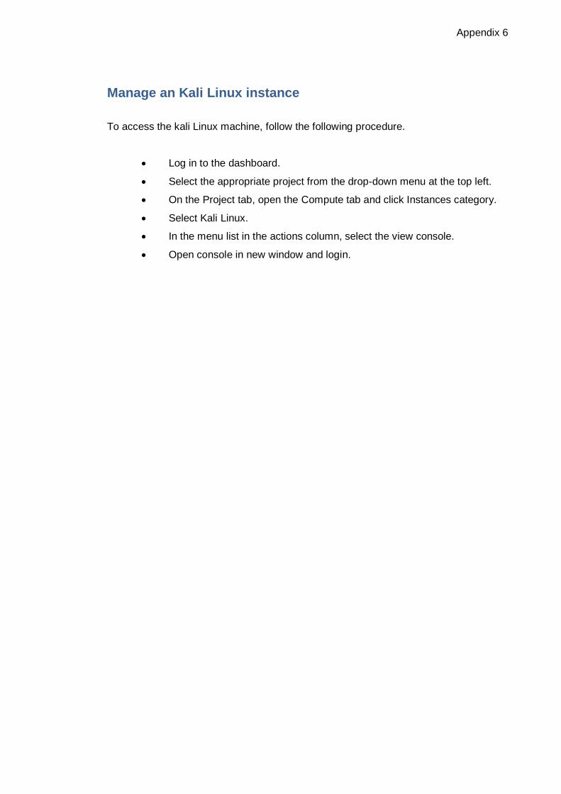
Appendix 6
Manage an Kali Linux instance
To access the kali Linux machine, follow the following procedure.
• Log in to the dashboard.
• Select the appropriate project from the drop-down menu at the top left.
• On the Project tab, open the Compute tab and click Instances category.
• Select Kali Linux.
• In the menu list in the actions column, select the view console.
• Open console in new window and login.