design and implementation aspects of the control...
TRANSCRIPT

DESIGN AND IMPLEMENTATION ASPECTS OF THE CONTROL SYSTEM AT THE FHI FEL
H. Junkes, W. Schöllkopf, M. Wesemann, FHI, Berlin, Germany Ralph Lange, AES, Princeton, New Jersey, USA; HZB, Berlin, Germany
Abstract A new mid-infrared FEL has been commissioned at the
Fritz-Haber-Institut (FHI) in Berlin. It will be used for spectroscopic investigations of molecules, clusters, nanoparticles and surfaces. The oscillator FEL is operated with 15 – 50 MeV electrons from a normal-conducting S-band linac equipped with a gridded thermionic gun and a chicane for controlled bunch compression. Construction of the facility building with the accelerator vault began in April 2010. First lasing was observed on Februar 15th, 2012. [1] The EPICS software framework was choosen to build the control system for this facility. The industrial utility control system is integrated using BACnet/IP. Graphical operator and user interfaces are based on the Control System Studio package. The EPICS channel archiver, an electronic logbook, a web based monitoring tool, and a gateway complete the installation. This paper presents design and implementation aspects of the control system, its capabilities, and lessons learned during local and remote commissioning.
CONTROL SYSTEM
Cavity Control and Stabilization A feedback system for stabilizing the FEL cavity length
has been installed. The HeNe-laser beam of a commercial interferometer (Agilent 10895A, VMEbus) is split in two beams (70 % and 30 %). The high-intensity beam passes through the FEL's 5.4-m-long cavity chamber, slightly angled with respect to the cavity axis, from one side of the cavity end mirror to the other side of the out-coupling mirror where it is reflected by a retroreflector. The low- intensity beam is directed to another retroreflector located on the opposite side of the cavity end mirror. [2] Furthermore, five out-coupling mirrors with different out-coupling hole sizes from 0.75 to 3.5 mm are mounted on a precision in-vacuum translation stage allowing to choose the hole size that is best suited for a given IR wavelength. Roll and pitch of the mirrors can be controlled by using in-vacuum pico motors (see Fig. 1).
The EPICS controls run on a VMEbus CPU (Emerson MVME3100) under the RTEMS real time OS.[3] A MAXv motion system is used to control the relative distance between the two cavity mirrors using motorized micrometer drives on the translation. User and operator interfaces allow a fine tuning of the cavity. Two motorized pin holes with camera view screens on each end of the cavity allow to easily define the home positions of the roll and pitch of the mirrors with the help of an external HeNe alignment laser. Long term stabilization is guaranteed by closed loop control using
EPICS records. This has been demonstrated during early commissioning.
Figure 1: Cavity and undulator.
IR Beam Diagnostic For monitoring the wavelength, a vacuum grating
monochromator (Acton VM-504, RS232-control via SD3 SpectraDrive Controller) in conjunction with a pyroelectric linear array detector (DIAS 128LT[4], see Fig. 2) is used.
The interface to the array is realized with a rtd-DM6430HR 16bit, 100kHz Analog I/O PC-104 module connected to a syslogic NETIPC/6. Debian Linux is used on the CPU board booting from CF card. The EPICS Input Output Controller (IOC) running on this board implements device support for ‘pyroArray’. A waveform record holds the profile of the last laser shot. The system is set up near the diagnostic chamber.
Figure 2: DIAS 128LT.
Machine Protection System Correct steering of the electron beam all the way to the
beam dump must be continuously monitored to disable further gun triggers in case of a failure. A Struck 3316 16 channel 250 MSPS 14bit VMEbus digitizer[5] is used to compare the signals from BPMs, current-transformer toroids, and the Faraday cup of the beam dump with the expectation values. If the comparison fails, RF will be switched off.
In our configuration the board takes only power from the VMEbus while all communication is routed through a Gigabit Ethernet connection (SFP at the front panel). The Struck card provides a communication server (XILINX
Soft Tri-Mode Ethernet MAC core), to which an IOC can send a command and obtain a response to read/write the internal memory of the device. The communication protocol at the application layer on the socket interface (UDP) does not have any standard. Currently we have implemented a C-library that we have yet to integrate into EPICS records (aSub).
Operator Console The operator interface is based on Control System
Studio (CSS). Taking advantage of modern graphical editor software technology, Operator Interface (OPI) editor and runtime - Best OPI, Yet (BOY) - has been developed by the CSS collaboration.[6] The Operator Interface is one of the basic components of the standard control system model. It provides not only operators but also scientists and engineers with rich graphical interfaces to view or operate the FEL locally or remotely used.
INTEGRATION INTO THE FHI ENVIRONMENT
Every user at the FHI will have the possibility to monitor the machine state of the FEL independent of the
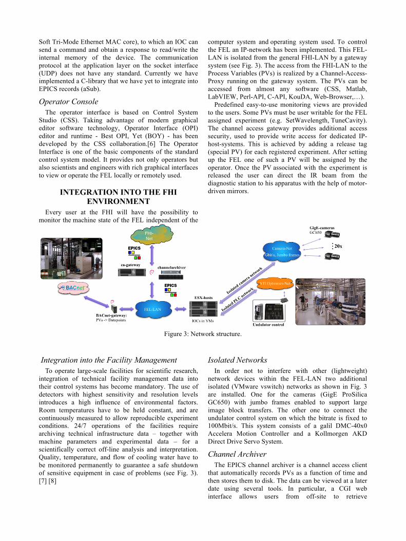
computer system and operating system used. To control the FEL an IP-network has been implemented. This FEL-LAN is isolated from the general FHI-LAN by a gateway system (see Fig. 3). The access from the FHI-LAN to the Process Variables (PVs) is realized by a Channel-Access-Proxy running on the gateway system. The PVs can be accessed from almost any software (CSS, Matlab, LabVIEW, Perl-API, C-API, KouDA, Web-Browser,…).
Predefined easy-to-use monitoring views are provided to the users. Some PVs must be user writable for the FEL assigned experiment (e.g. SetWavelength, TuneCavity). The channel access gateway provides additional access security, used to provide write access for dedicated IP-host-systems. This is achieved by adding a release tag (special PV) for each registered experiment. After setting up the FEL one of such a PV will be assigned by the operator. Once the PV associated with the experiment is released the user can direct the IR beam from the diagnostic station to his apparatus with the help of motor-driven mirrors.
Figure 3: Network structure.
Integration into the Facility Management To operate large-scale facilities for scientific research,
integration of technical facility management data into their control systems has become mandatory. The use of detectors with highest sensitivity and resolution levels introduces a high influence of environmental factors. Room temperatures have to be held constant, and are continuously measured to allow reproducible experiment conditions. 24/7 operations of the facilities require archiving technical infrastructure data – together with machine parameters and experimental data – for a scientifically correct off-line analysis and interpretation. Quality, temperature, and flow of cooling water have to be monitored permanently to guarantee a safe shutdown of sensitive equipment in case of problems (see Fig. 3). [7] [8]
Isolated Networks In order not to interfere with other (lightweight)
network devices within the FEL-LAN two additional isolated (VMware vswitch) networks as shown in Fig. 3 are installed. One for the cameras (GigE ProSilica GC650) with jumbo frames enabled to support large image block transfers. The other one to connect the undulator control system on which the bitrate is fixed to 100Mbit/s. This system consists of a galil DMC-40x0 Accelera Motion Controller and a Kollmorgen AKD Direct Drive Servo System.
Channel Archiver The EPICS channel archiver is a channel access client
that automatically records PVs as a function of time and then stores them to disk. The data can be viewed at a later date using several tools. In particular, a CGI web interface allows users from off-site to retrieve

configuration and telemetry data from the time of their run. [9]
Development Environment To allow easy and secure development both locally and
remotely, widely-used standards and best-practice examples have been followed wherever possible. All control system software and applications are under revision control, using the Mercurial software configuration management system.[10] A publicly accessible repository server has been set up, allowing local and remote developers to easily access and browse the software. SSH remote access is provided through the FHI infrastructure, and the NX [11] remote desktop application allows to run graphical applications remotely for tests and debugging. Development and production data are kept separate on file system level, so that only authorized developers are able to deploy software into the production system.
Documentation The Web application ELOG [12] is used as electronic
logbook at the FHI by different groups (mostly as group-shared logbooks). The ELOG has been extended by a low level postscript service to offer a platform independent input interface (we have learned from DESY E-logbook). [13]
OUTLOOK
Electron Gun High-voltage Power Supply A custom of-the-shelf thermionic electron gun,
manufactured for use in commercial inductive output tubes (IOTs), is used in the accelerator front-end.[14] The gun high-voltage (HV) power supply, developed at the FHI, is shown in Fig. 4. It supplies a maximum cathode DC voltage of -50 kV. The power supplies for the cathode heater and grid bias voltage are floating on the HV potential. They are controlled via fiber links (MOXA TC-90) isolating the HV and connecting the power supplies’ RS232 interfaces to a 4-port terminal server (MOXA NPort 6450 Series). In addition, a fast HV solid-state switch (Behlke HTS-651) allows to switch off the high voltage between the accelerator pulses, which are up to 20 µs long and repeated with up to 20 Hz.
Figure 4: Electron Gun High-voltage Power Supply.
Various interlocks (HW and SW) have been implemented to protect the gun from damage in any of the fault cases including poor vacuum, insufficient grid bias voltage, not enough (or too much) cathode heating power, or a fault state of the HV switch. The EPICS interlock watchdog is running on a separate interlock IOC.
User Experiment: Conformer Resolved IR-Spectroscopy on Biomolecules • The function on protein depends on its 3-
dimensional structure and shape. • The study of proteins in the gas phase yields
information about isolated molecules and gives insight into intramolecular interactions that govern the protein's structure.
• The gas-phase techniques mass spectrometry (MS), ion mobility spectrometry (IMS), and IR-spectroscopy yield complementary information about the molecule.
The principle of Ion Mobility Spectroscopy: • Combination of IMS, MS, and IR-Spectroscopy
allows for spectroscopy on m/z- and shape-selected biomolecules.
• Shape- and m/z-selected ions will be stored in a cooled ion trap and irradiated with IR-light.
• The wavelength dependency of the ion-fragmentation will be monitored using LabVIEW programs and NI data acquisition cards.[15]
Figure 5: Ion mobility cell.
Figure 6: Arrival time distribution.
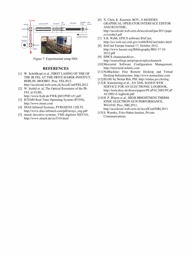
Figure 7: Experimental setup IMS.
REFERENCES [1] W. Schöllkopf et al., FIRST LASING OF THE OF
THE IR FEL AT THE FRITZ-HABER-INSTITUT, BERLIN, MOOB01, Proc. FEL2012. http://accelconf.web.cern.ch/AccelConf/FEL2012
[2] W. Seidel et. al, The Optical Resonator of the IR-FEL at ELBE, http://www.hzdr.de/FWK/jb03/PDF/s51.pdf
[3] RTEMS Real Time Operating System (RTOS), http://www.rtems.com
[4] DIAS Infrared Systems, PYROSENS 128LTI, http://www.dias-infrared.com/pdf/arrays_eng.pdf
[5] struck inovative systeme, VME digitizer SIS3316, http://www.struck.de/sis3316.html
[6] X. Chen, K. Kasemir, BOY, A MODERN GRAPHICAL OPERATOR INTERFACE EDITOR AND RUNTIME, http://accelconf.web.cern.ch/accelconf/pac2011/papers/weobn3.pdf
[7] S.B. Webb, EPICS software BACnet, http://ics-web.sns.ornl.gov/webb/BACnet/index.html
[8] BACnet Europe Journal 17, October 2012, http://www.bacnet.org/Bibliography/BEJ-17-10-2012.pdf
[9] EPICS channelarchiver, http://sourceforge.net/projects/epicschanarch
[10] Mercurial Software Configuration Management, http://mercurial.selenic.com
[11] NoMachine: Free Remote Desktop and Virtual Desktop Infrastructure, http://www.nomachine.com
[12] ELOG by Stefan Ritt, PSI, http://midas.psi.ch/elog. [13] R. Kammering et al., AN XML BASED WEB
SERVICE FOR AN ELECTRONIC LOGBOOK, http://tesla.desy.de/doocs/papers/PCaPAC2002/PCaPAC2002-E-logbook.pdf.
[14] H. P. Bluem et al., HIGH BRIGHTNESS THERM-IONIC ELECTRON GUN PERFORMANCE, WG1010, Proc. ERL2011. http://accelconf.web.cern.ch/AccelConf/ERL2011
[15] S. Warnke, Fritz-Haber-Institut, Private Communications.