design and fabrication of adjustable ceiling fan
TRANSCRIPT

DESIGN AND FABRICATION OF ADJUSTABLE CEILING FAN BLADE CLEANER
MUIHAMAD RUSYDI BIN AL!
A project report submitted in partial fulfilment of the
requirements for the award of the Diploma
of Mechanical Engineering
Faculty of Mechanical Engineering
Universiti Malaysia Pahang
NOVEMBER 2007

ABSTRACT
This thesis is based on the project about design and fabrication of adjustable
ceiling fan blade cleaner. 'Adjustable Ceiling fan blade cleaner' is equipment that
can clean the blade ceiling fan. The fabrication of this product started with surveying
in market about the product, specification analysis, concept designing, detail concept
designing and fabrication of the product. Four (4) products were selected from the
market for the analysis and investigation. One types of the product that suitable and
fit all the specification was chosen to fabricate. The investigation was made in scope
of the constraint that may occur for the development of the product and relevance of
the product manufacturing processes. This product have been fabricate according to
engineering method through many fabrication process such as welding, cutting,
drilling and assembling. For development of this project and future works, some
suggestion was made for upgrading the product. The suggestion like dust case and
more durable of the holder to make sure this product will competitive with the
existing products in the market.
vi

ABSTRAK
Projek Tahun Akhir mi adalah mengenai "adjustable ceiling fan blade
cleaner" yang merupakan alat yang digunakan untuk mencuci bilah kipas suing.
Proses penghasilan produk telah dimulakan dengan membuat tinjauan terhadap
pasaran, penganalisan spesifikasi produk, reka bentuk konsep, reka bentuk kosep
yang terperinci, dan penghasilan produk. Terdapat empat (4) produk di pasaran yang
dikenal pasti dan di senaraikan untuk tujuan kajian dan analisis. Setelah dianalisis
kesemua produk, satu produk yang menepati kesemua spesifikasi yang telah
ditetapkan telah dipilih. Kajian di buat dengan melihat kesesuaian produk terhadap
proses pengeluaran dan halangan yang timbul seperti ketiadaan bahan serta keadaan
mesin di dalam menghasilkan produk mi. Produk mi dihasilkan mengikut cara
kejuruteraan seperti mengimpal, memotong, menggerudi dan mencantum. Beberapa
cadangan telah dibuat untuk menambahbaik produk tesebut. Diantaranya ialah bekas
penampung habuk dan juga bahan pemegang produk tersebut yang akan
menggunakan bahan yang lebih tahan untuk memastikan produk mi mampu bersaing
dengan produk yang sedia ada di pasaran.
vi'

TABLE OF CONTENTS
CHAPTER
TITLE PAGE
SUPERVISOR DECLARATION ii
DECLARATION iii
DEDICATION iv
ACKNOWLEDGEMENTS v
ABSTRACT vi
ABSTRAK vii
TABLE OF CONTENTS viii
LIST OF TABLES xi
LIST OF FIGURES xii
I INTRODUCTION I
1.1 Project Synopsis I
1.1.1 General Project Synopsis I
1. 1.2 Specific Project Synopsis I
1.2 Problem Statement 2
1.3 Project Scope 2
1.4 Project Objective 2
1.5 Project Planning 3
viii

ix
2
LITERATURE REVIEW 4
2.1 Introduction 4
2.2 Theoretical Review 5
2.2.1 Housekeeping Tool 5
2.3 Technical Review 5
2.4 Joining Method Of Welding Process 6
2.4.1 Basic Theory of Metal Inert Gas(MIG) Welding 6
2.4.2 The Advantages of MIG Welding 7
2.4.3 The Disadvantages of MIG Welding 7
2.4.4 Welding Gun and Wire Feed Unit 8
2.4.5 Process of MIG Welding 8
3 PROJECT METHODOLOGY 11
3.1 Project Flow Chart 11
3.2 Design 14
3.2.1 Introduction 14
3.2.2 Concept Selection Method 14
3.2.3 Concept Generation and Evaluation 21
3.2.4 Selection Criteria/Concept 22
3.2.5 Product Design Specification 23
3.2.6 Engineering Drawing Of The Design 23
3.3 Fabrication Process 30
3.3.1 Find the Material 30
3.3.2 Cutting the Material 31
3.3.3 Joining the Material 32
3.3.4 Spraying the Product 33

x
5
RESULT AND DISCUSSION 35
4.1 Introduction 35
4.2 Result 35
4.2.1 Product Specification 37
4.2.2 Costing 37
4.3 Project Problems 38
4.3.1 Literature Review 38
4.3.2 Designing and Sketching 38
4.3.3 Material Preparation 38
4.3.4 Fabrication Process 39
4.3.5 Types of Defect 39
4.4 Discussion 41
CONCLUSION AND RECOMMENDATION 43
5.1 Introduction 43
5.2 Project Conclusion 43
5.3 Recommendations and Future Work 44
5.3.1 Facilities 44
5.3.2 Student Budget 44
5.3.3 Future Work 44
REFERENCES 46

LIST OF TABLES
TABLE NO. TITLE
PAGE
1.1 Project schedule
3.8 Concept generation and evaluation 21
4.4 Product specification 37
4.5 Costing 37
xi
LIST OF FIGURE
FIGURE NO. TITLE PAGE
2.1 Vacuum ceiling fan blade cleaner 5
2.2 Ceiling fan blade cleaner with dust holder 5
2.3 Wiper type ceiling fan blade cleaner 6
2.4 Basic Structure of Metal Inert Gas (MIG) Welding 6
2.5 GMAW torch nozzle cutaway image 8
2.6 Basic equipment used in MIG operations 9
2.7 GMAW weld area 9
3.1 Project flow chart 13
3.2 Concept A 15
3.3 Concept 16
3.4 Concept C 17
3.5 Concept 18
3.6 Concept E 19
3.7 Concept F 20
3.9 3D Frame 24
3.10 3DBody 24
3.11 3D Cleaner device 25
3.12 3D Connector 25
3.13 3D Adjustable holder 26
xl'
xlii
3.14 3D Cleaner section 26
3.15 3D Full assembly 27
3.16 2D Cleaner section 27
3.17 2DAdjustable holder 28
3.18 2D Full assembly 29
3.19 Paint roller 30
3.20 PVC plastic rod 30
3.21 Measurement and marking the material 31
3.22 Cutting the material 31
3.23 Grind using hand grinding 32
3.24 Welding process 32
3.25 Drilling process 33
3.26 After spraying the product 33
3.27 Painting using spray 34
4.1 Front view 36
4.2 Top view 36
4.3 Side view 36
4.6 Bead at the joint 39
4.7 Gap at the joint section 40
4.8 Improper cutting at the upper and bottom holder 41
CHAPTER 1
INTRODUCTION
1.1 Project Synopsis
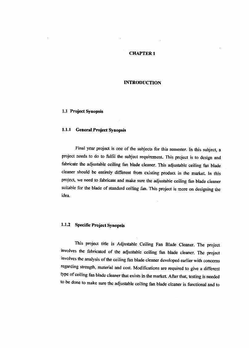
1.1.1 General Project Synopsis
Final year project is one of the subjects for this semester. In this subject, a
project needs to do to fulfil the subject requirement. This project is to design and
fabricate the adjustable ceiling fan blade cleaner. This adjustable ceiling fan blade
cleaner should be entirely different from existing product in the market. In this
project, we need to fabricate and make sure the adjustable ceiling fan blade cleaner
suitable for the blade of standard ceiling fan. This project is more on designing the idea.
1.1.2 Specific Project Synopsis
This project title is Adjustable Ceiling Fan Blade Cleaner. The project
involves the fabricated of the adjustable ceiling fan blade cleaner. The project
involves the analysis of the ceiling fan blade cleaner developed earlier with concerns
regarding strength, material and cost. Modifications are required to give a different
type of ceiling fan blade cleaner that exists in the market. After that, testing is needed
to be done to make sure the adjustable ceiling fan blade cleaner is functional and to
FJ
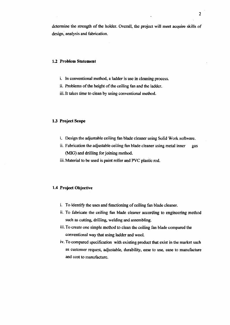
determine the strength of the holder. Overall, the project will meet acquire skills of
design, analysis and fabrication.
1.2 Problem Statement
i. In conventional method, a ladder is use in cleaning process.
ii. Problems of the height of the ceiling fan and the ladder.
iii.It takes time to clean by using conventional method.
13 Project Scope
i. Design the adjustable ceiling fan blade cleaner using Solid Work software.
ii. Fabrication the adjustable ceiling fan blade cleaner using metal inner gas
(MIG) and drilling for joining method.
iii.Material to be used is paint roller and PVC plastic rod.
1.4 Project Objective
i. To identify the uses and functioning of ceiling fan blade cleaner.
ii. To fabricate the ceiling fan blade cleaner according to engineering method
such as cutting, drilling, welding and assembling.
iii.To create one simple method to clean the ceiling fan blade compared the
conventional way that using ladder and wool.
iv. To compared specification with existing product that exist in the market such
as customer request, adjustable, durability, ease to use, ease to manufacture
and cost to manufacture.

1.5 Project Planning
Table 1.1: Project schedule
Project
Activities Weeks
Literature
Review
Design &
Measurement
consideration
Acquisition &
Material
preparation
Methodology
study
Fabrication
Evaluation &
Improvement
Report writing
Presentation
CHAPTER 2
LITERATURE REVIEW
2.1 Introduction
Ceiling fan blades collect lots of dust, and then they spread it around. A
ceiling fan blade cleaning device includes a fork member and a separable cleaner
member. The fork member has a tubular handle by which the user holds the device
for cleaning purposes. The cleaner member is formed of fibrous web material and
has a rectangular central portion formed of a pair of spaced apart rectangular webs
presenting an opening into which a ceiling fan blade may extend for simultaneous
cleaning of its upper and lower surfaces. Users do not have to stand on a chair to
clean their ceiling fan blade.
This adjustable ceiling fan blade cleaner commonly produces by PVC plastic
rod, plastic and fabric. This items has been chosen because strength, light in weight,
easy to fabricate, long life and etc. This adjustable ceiling fan blade cleaner also
commonly fabricate using welding method such as MIG welding to joining part that
been made by steel. This method has been chosen because can produce the durable,
clean and interesting adjustable ceiling fan blade cleaner.

2.2 Theoretical Review
2.2.1 Housekeeping Tool
The ceiling fan blade cleaner is to cleaning the ceiling fan blade. This ceiling
fan blade cleaner commonly used at the house, school, office and etc.
2.3 Technical review
Figure 2.1: Vacuum ceiling fan blade cleaner
Figure 2.2: Ceiling fan blade cleaner with dust holder
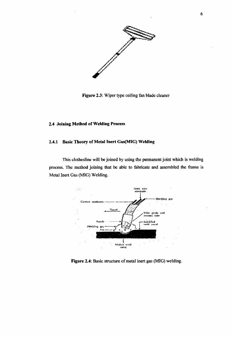
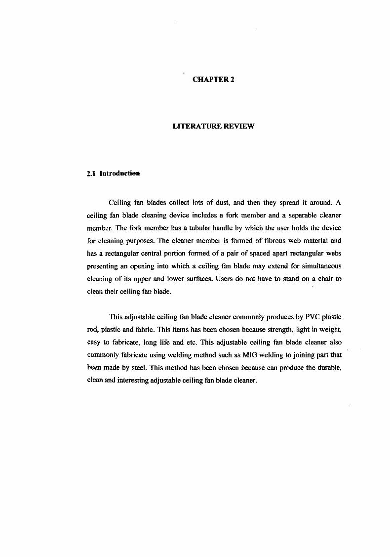
Figure 2.3: Wiper type ceiling fan blade cleaner
2.4 Joining Method of Welding Process
2.4.1 Basic Theory of Metal Inert Gas(MIG) Welding
This clothesline will be joined by using the permanent joint which is welding
process. The method joining that be able to fabricate and assembled the frame is
Metal Inert Gas (MIG) Welding.
Id tIr
hkld1rig g Cftd Conductor
SI.
J//// nIL
—1LJ
thf.kiig '- I"IrI roI.l
Moftn s'dd - metal
Figure 2.4: Basic structure of metal inert gas (MTG) welding.
7
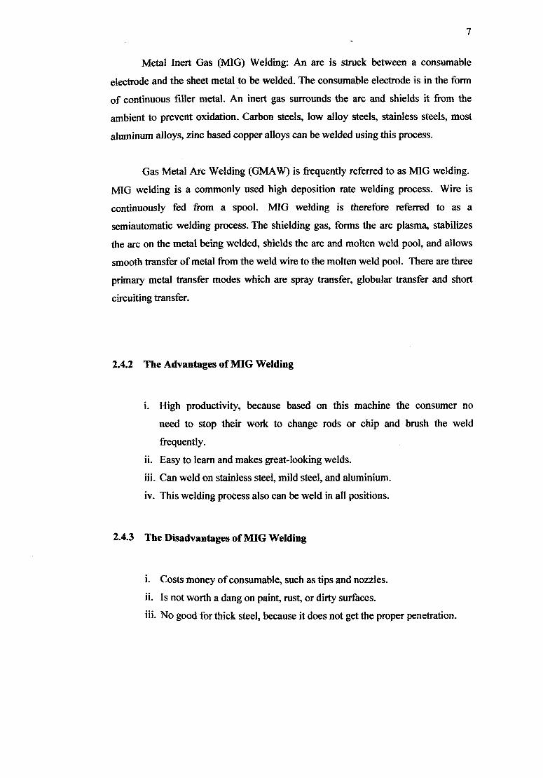
Metal Inert Gas (MIG) Welding: An arc is struck between a consumable
electrode and the sheet metal to be welded. The consumable electrode is in the form
of continuous filler metal. An inert gas surrounds the arc and shields it from the
ambient to prevent oxidation. Carbon steels, low ahoy steels, stainless steels, most
aluminum alloys, zinc based copper alloys can be welded using this process.
Gas Metal Arc Welding (GMAW) is frequently referred to as MIG welding.
MIG welding is a commonly used high deposition rate welding process. Wire is
continuously fed from a spool. MIG welding is therefore referred to as a
semiautomatic welding process. The shielding gas, forms the arc plasma, stabilizes
the arc on the metal being welded, shields the arc and molten weld pool, and allows
smooth transfer of metal from the weld wire to the molten weld pool. There are three
primary metal transfer modes which are spray transfer, globular transfer and short
circuiting transfer.
2.4.2 The Advantages of MIG Welding
i. High productivity, because based on this machine the consumer no
need to stop their work to change rods or chip and brush the weld
frequently.
ii. Easy to learn and makes great-looking welds.
iii. Can weld on stainless steel, mild steel, and aluminium.
iv. This welding process also can be weld in all positions.
2.4.3 The Disadvantages of MIG Welding
i. Costs money of consumable, such as tips and nozzles.
ii. Is not worth a dang on paint, rust, or dirty surfaces.
iii. No good for thick steel, because it does not get the proper penetration.

8
2.4.4 Welding Gun and Wire Feed Unit
The Figure 2.5 has shown the basic structure on the nozzle of the MTG
welding.
Figure 2.5: GMAW torch nozzle cutaway image. (1) Torch handle, (2) Molded phenolic dielectric (shown in white) and threaded metal nut insert (yellow),
(3) Shielding gas nozzle, (4) Contact tip (5) Nozzle output face.
2.4.5 Process of MIG Welding
In spray transfer, small, molten metal droplets from the electrode are transfer
to the weld area at a rate of several hundred droplets per second. The transfer is
spatter-free and very stable. High Direct Current (DC) and voltages and large-
diameter electrodes are used with argon or argon-rich gas mixture used as the
shielding gas. The average current required in this process can be reduced by using a
pulsed arc, which superimposes high-amplitude pulses onto a low, steady current.
The process can use in all welding positions.
In globular transfer, carbon-dioxide-rich gases are utilized, and globules are
propelled by the forces of the electric-arc transfer of the metal, resulting in
considerable spatter. High welding currents are used, making it possible for greater
weld penetration and higher welding speed than are achieved in spray transfer.
Heavier sections commonly are joined by this method.

9
In short circuiting, the metal is transferred in individual droplets (more than
50 per second), as the electrode tip touches the molten weld metal and short circuits.
Low currents and voltages are utilized with carbon-dioxide-rich gases and electrodes
made of small-diameter wire. The power required is about 2 kW.
Feed control Wire SlMdijig-
Control system -.T-'r"fl f!s gs -
ic.as
Lsuuice O5
Wrkp ce Gun cotioi ui
fl rnntrol 14
Ve-feed' I IOV I drive nioter supply I 1
Conactor \ ekIin
control machine
Figure 2.6: Basic equipment used in MIG operations
Figure 2.7: GMAW weld area. (1) Direction of travel, (2) Contact tube, (3) Electrode, (4) Shielding gas, (5) Molten weld metal, (6) Solidified weld metal, (7)
Work piece.

10
In most of its applications, gas metal arc welding is a fairly simple welding
process to learn, requiring no more than several days to master basic welding
technique. Even when welding is performed by well-trained operators, however,
weld quality can fluctuate, since it depends on a number of external factors. And all
GMAW is dangerous, though perhaps less so than some other welding methods, such
as shielded metal arc welding.
CHAPTER 3
PROJECT METHODOLOGY
3.1 Project Flow Chart
In fabrication of adjustable ceiling fan blade cleaner, there is a planning of
the overall progress to assure the project can be finish on schedule. This project
started with the literature review and research about the product. The main important
of the project is determination the objective. Then, study and make a lot of
investigation about ceiling fan blade cleaner. This is including a review concept of
the cleaner, fan technology, and type of cleaner use in various ceiling fan blade
cleaner. These tasks have been done through research on the internet, books and
others sources.
The project will be continuing with the design process. In this stage, the
knowledge and lessons that have studied will be applied in sketching. It is important
to make a suitable design for the project. After several design sketched, design
consideration have been made and one of the design have been chosen. The selected
sketch will be transfer to solid modelling and engineering drawing by using Solid
Works program.
After all the engineering drawing finished, the drawing was used as a
reference for the next process, which it is fabrication stage. This process is consists
fabricate all the parts that have design before by following all the dimension using
various type of manufacturing process. The manufacturing process included in this
Process is welding, cutting, drilling and others. During the fabrication process, if
12
there is something wrong occur, such as not balance dimension so the process will be
stop and go back to previous step, make a modification against the current design.
Testing stage has been implementing after fabrication stage. The testing is to
gathered information about strength, durability, and safety of the design that has been
fabricated. Due to some problem that will discuss later in other chapter, the testing
only can be made on several aspect only. During the testing, if problem occur such as
malfunction, the process step back to previous process, which is fabrication. If the
cleaning process is working, the project will be declaring success.
Then, all the process mentioned above is done; all the material for report
writing is gathered. The report writing process will be guided by the UMP final year
project report writing. The project ended after the submission of the report and the
slide presentation has been present.

START
LITERATURE REVIEW
REVIEW CURRENT DESIGN
NEW DESIGN
FABRICATION
I MODIFICATION I
TESTING >- NO I
kEsiREPORT
PRESENTATION
END
13
Figure 3.1: Project flow chart

14
3.2 Design
3.2.1 Introduction
The design of the adjustable ceiling fan blade cleaner must be compliance to
several aspects. The design consideration must be done carefully so the design can be
fabricated and the ceiling fan blade cleaner functioning. The aspect that must be
considered in designing the adjustable ceiling fan blade cleaner table is:
3.2.1.1 Adjustable : This ceiling fan blade cleaner should have adjustable aspect
compared other ceiling fan blade cleaner that exist in the
market.
3.2.1.2 Material : The material that will choose must be suitable such as light in
weight to fabricate this adjustable ceiling fan blade cleaner.
3.2.1.3 Cost : It depends on material and manufacturing process was chosen.
3.2.2 Concept Selection Method
The design of adjustable ceiling fan blade cleaner must through process of
concept selection method. It includes selecting four current designs that exist in the
market and sketching two designs of ceiling fan blade cleaner that have certain
characteristic and advantages. The selection and sketching of ceiling fan blade
cleaner table is:

15
Concept A
("eilhi ng Fan Bush. • tiI) aiid:ai1ti:.n of
bck'
5Ill tip :ariIIS
i[.i1 !1I)iriJr
• F uI1I'. J L1,10,11 I
* FI'xibI 12d an be 1 - •idjiitii
Figure 3.2: Concept A
It is known as datum concept because this cleaner already found in the
market. The advantages of this design are light and easy to use. The disadvantages of
this design are the cleaning process not very clean and it easily to bend when
cleaning process.