design and control of vehicle trailer with onboard power
TRANSCRIPT

INTRODUCTIONIn this project, we propose and analyze a concept for a trailer with its own on-board power supply. This allows the trailer to be towed by a relatively small vehicle, which would not be able to tow a non-powered trailer. The purpose of this design is to allow someone with occasional towing needs to avoid the need for a larger vehicle, either rented or purchased, to serve those occasional needs.
This concept includes two significant innovations. The first is the inclusion of the power source on the trailer. There are many trailers available for towing a variety of different types of loads, but they are designed to be propelled by the engine or other power source of the towing vehicle. Some trailer designs do include unique features, such as the steerable trailer proposed by Ryu et al. [1], but no existing trailer moves under its own power, with the towing vehicle providing primarily guidance. The second innovative concept is the use of a load-sensing trailer hitch to provide a feedback signal to the trailer's controller. Some similar prior art exists in this regard, e.g. a load sensing trailer hitch used for detecting problems with alignments/towing, but these existing hitch designs are not used for our purpose. There are also trailer hitches including shock absorption, but they do not include sensing [2, 3, 4, 5].
Some modeling work has been done on vehicle-trailer systems as well, e.g. [1, 6, 7, 8, 9], and there has been some work on control systems for trailers in order to incorporate braking for safety purposes [10]; however, these models focus on the trajectory tracking problem and
directional control, rather than power control, and so significant modeling was required in order to carry out this project. This modeling work was the focus of the first phase of the project; the second phase was the design of a control system, and the third and final phase involved some preliminary optimization work on the model.
This paper is organized as follows: first, the modeling of all the systems is presented. This includes the models of the small car, trailer, on board power supply for the trailer and the hitch. Each is modeled as an individual system, and then they are connected to each other using the Mathworks® software Simulink.
In the next section of the paper, the control system is selected and designed for maintaining the trailer's motion in proportion with the small car's motion. The controller chosen is a proportional controller. This controller was selected to be the simplest possible controller. Although the proportional controller does have significant limitations, including the presence of a steady state error, we are using this to check the feasibility of the design. Future work will include a more sophisticated controller.
After this, the model is optimized and the system performance is evaluated for some simple maneuvers. While further optimization is desirable, along with more extensive analysis, this does show the basic feasibility of the concept.
Following the description of the work, a summary of key findings and conclusions is given, and future work is noted.
Design and Control of Vehicle Trailer with Onboard Power Supply
Sibi Visht Sankara Narayanan and Diane PetersKettering University
ABSTRACTTypically, when someone needs to perform occasional towing tasks, such as towing a boat on a trailer, they have two choices. They can either purchase a larger, more powerful vehicle than they require for their regular usage, or they can rent a larger vehicle when they need to tow something. In this project, we propose a third alternative: a trailer with an on-board power supply, which can be towed by a small vehicle. This system requires a means of sensing how much power the trailer's power supply should provide, and an appropriate control system to provide this power. In this project, we design and model the trailer, a standard small car, and the control system, and evaluate the concept's feasibility. We have selected a suitable power source for the trailer, a DC motor, coupled directly to the trailer's single drive wheel, which allow us to dispense with the need for a differential. The trailer hitch is designed to include force sensing capability, to determine whether the trailer is moving under its own power or being towed by the vehicle. There is a control system, designed to maintain a zero force in the hitch, thus ensuring that the trailer is providing enough power. This system will enable someone with occasional towing needs to perform these tasks with their standard vehicle, and avoid the need for a larger vehicle.
CITATION: Sankara Narayanan, S. and Peters, D., "Design and Control of Vehicle Trailer with Onboard Power Supply," SAE Int. J. Passeng. Cars – Electron. Electr. Syst. 8(1):2015, doi:10.4271/2015-01-0132.
2015-01-0132Published 04/14/2015
Copyright © 2015 SAE Internationaldoi:10.4271/2015-01-0132
saepcelec.saejournals.org
32
Downloaded from SAE International by Diane Peters, Saturday, February 13, 2016

Modeling of the SystemModeling and design have been performed for the four basic parts of the system which are,
1. Model of the standard small car 2. Model of the trailer 3. Model of the On Board power supply system 4. Model of the hitch
These parts were then combined into a complete system model. Each part of the system is modelled using Mathworks® software Simulink. The detailed description of the modelling and design of various components of the system are discussed below.
1. Model of Standard Small CarWhile complex vehicle models can be created, for the purposes of this work a simple model was used. The vehicle dynamics of the small car are assumed to be adequately represented by a bicycle model, which has only three degrees of freedom. Since the focus of this work is on the trailer, the drivetrain of the vehicle was not modeled; it was assumed to be able to achieve the specified speeds and paths used in the analysis.
Bicycle ModelGenerally a vehicle is associated with lots of degrees of freedom. But for making it simple and considering only the lateral and the yaw motions of a vehicle and the angle associated with it, we consider only three degrees of freedom and thus the vehicle can be considered in two wheels as illustrated below. This is called the bicycle model in vehicle dynamics.
Figure 1. Three degree of freedom model [11]
EquationsThus, from the bicycle model, we can be able to obtain the equations which determine the various parameters of the standard small car. The equations for the different parameters, taken from [12], are listed below:
Thus we will be able to obtain our , and for the standard small car and can put them into Simulink.
The model of the car has been simulated in Simulink using the above equations, such that the velocity of the car ( and ) and the yaw rate ( ) can be obtained for further processing. The inputs to be given are the steering angle (δ) and the force in the forward direction (Fx).
2. Model of the TrailerWe have designed a three wheel trailer, which has a single front wheel. This front wheel is the drive wheel, which is coupled to the onboard power source. By using a single drive wheel, we eliminate the need for a differential, which produces a simpler design. The trailer's center of gravity will be designed to fall between the line of axis of the front wheel and the center of the rear axle.
Free Body Diagram of the TrailerThe free body of the trailer is shown below,
Figure 2. Free body diagram of the trailer
Equations of the TrailerThe equations of the trailer, describing the linear and angular acceleration and velocity, were derived based on the free-body diagram in Figure 2. The initial equations are given below, followed by the necessary equation development to construct the model.
Sankara Narayanan et al / SAE Int. J. Passeng. Cars – Electron. Electr. Syst. / Volume 8, Issue 1 (May 2015) 33
Downloaded from SAE International by Diane Peters, Saturday, February 13, 2016
Velocity of the TrailerDuring a turn,
At straight roads,
Acceleration of the TrailerAt straight roads,
During a turn,
Where,
R- Radius of the turn
Angular Velocity of the Trailer:
Angular Acceleration of the Trailer:
Where,
ΣMomentC.G. = (Fhitch.e) - Tfinal drive + (a.Wf) + (2b.Wr)
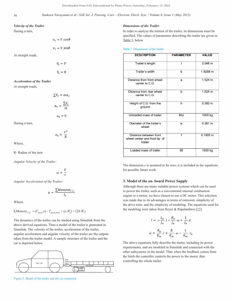
The dynamics of the trailer can be studied using Simulink from the above derived equations. Then a model of the trailer is generated in Simulink. The velocity of the trailer, acceleration of the trailer, angular acceleration and angular velocity of the trailer are the outputs taken from the trailer model. A sample structure of the trailer and the car is depicted below.
Figure 3. Model of the trailer and the car connected
Dimensions of the TrailerIn order to analyze the motion of the trailer, its dimensions must be specified. The values of parameters describing the trailer are given in Table 1, below
Table 1. Dimensions of the trailer
The dimension e is assumed to be zero; it is included in the equations for possible future work.
3. Model of the on- board Power SupplyAlthough there are many suitable power systems which can be used to power the trailer, such as a conventional internal combustion engine or a motor, we have chosen to use a DC motor. This selection was made due to its advantages in terms of emission, simplicity of the drive train, and the simplicity of modeling. The equations used for the modeling were taken from Reyer & Papalambros [13].
The above equations fully describe the motor, including its power requirements, and are modeled in Simulink and connected with the other subsystems in the model. Thus when the feedback comes from the hitch the controller controls the power to the motor, thus controlling the whole trailer.
Sankara Narayanan et al / SAE Int. J. Passeng. Cars – Electron. Electr. Syst. / Volume 8, Issue 1 (May 2015)34
Downloaded from SAE International by Diane Peters, Saturday, February 13, 2016

The motor should be selected according to the power requirements for the trailer with respect to the car. This can be done by taking into consideration of the load in trailer, maximum acceleration of the car and the maximum velocity for the trailer.
Based on these factors, calculations are made to obtain the power requirements for the trailer; this is documented for the unloaded and loaded conditions in Table 2.
Table 2. Power Requirements for the trailer at various speeds
Where the key parameters used are listed in Table 3.
Table 3. Parameters and their description
The Figure shows the power required for the trailer to propel at various speeds at both loaded and unloaded conditions.
Figure 4. Minimum Power required for trailer to move at various speed
The following calculations show the power required for the motor to propel the trailer at the maximum acceleration of a small hatchback, which has a 0 - 60 mph time of 10 seconds.
Average Small Hatchback Car
0-60 mph time = 10 s
Maximum Acceleration = 2.68 m/s^2
i. Loaded Condition of Trailer:
ii. Unloaded Condition of Trailer:
The following calculations show the power required by the DC motor to propel the trailer for various accelerations.
Sankara Narayanan et al / SAE Int. J. Passeng. Cars – Electron. Electr. Syst. / Volume 8, Issue 1 (May 2015) 35
Downloaded from SAE International by Diane Peters, Saturday, February 13, 2016

Table 4. Power required at various accelerations
Figure 5. Power Required for Acceleration
The parameters taken into consideration for the following calculations are listed below, in Table 5.
Table 5. General Parameter Details
From all the above analysis, it is evident that the power produced by the motor must be at least 75 horsepower.
DC Motor Requirements = 75 hp
4. Model of the HitchThe hitch is the most important part, which connects the car with the trailer. So, the hitch should be designed in such a way that the force between the car and the trailer is measured and the signals are sent to the controller. For this purpose, the hitch's construction is added along with certain components like,
• Load Cell • Spring • Damper system
A schematic of the hitch has been shown below.
Figure 6. Model of the load sensing hitch (images of spring, damper and load cell taken from publically available Google Images)
The equations of the hitch are derived according to the components connected in it and are simulated in Simulink, so that the forces of the car and the forces of the trailer can be compared and then the hitch sends the signals to the controller. Thus the controller then decides how much power is to be given to the power source of the trailer.
In our system, we ideally want the force at the hitch to be zero. The controller will compare the actual force sensed to this ideal value, and adjust the power supplied by the DC motor to the trailer, so that the trailer moves completely on its own power source following the path of the car.
5. Overview of the Complete SystemAll the individual parts of the system are connected together as a single model by adding a few additional inputs and connections to the existing parts so that the simulation can be done and our results can be verified. The overview of the system is also shown below.
Sankara Narayanan et al / SAE Int. J. Passeng. Cars – Electron. Electr. Syst. / Volume 8, Issue 1 (May 2015)36
Downloaded from SAE International by Diane Peters, Saturday, February 13, 2016

Figure 7. Overview of the system
Control System DesignThere should be a proper control system designed for the perfect functioning of the trailer, which is attached to the car, so that the trailer and the car can move at the same speed. This implies that the trailer will be made to accelerate or decelerate in proportion to the motion of the car. In this situation, the best suitable controller for the vehicle is the proportional controller.
In general, a Proportional controller is one which takes more time to achieve the goal by stepping up or down the inputs of the electric motor (in our case). Although the proportional controller has a steady state error, it achieves almost perfect conditions, where the force between the hitch connecting the car and trailer will be zero. Thus this enables us to keep the design simpler and to check the feasibility of our concept. In our future work we intend to use a more sophisticated controller such as the proportional Integral Controller or proportional integral derivative controller which can eliminate the steady state error and to achieve the zero force on the hitch faster.
In order to use the tools developed for linear systems, the equations for the trailer were linearized about a set operating point. The equations are then in the form of
Where,
Root locus plots were generated for this system, indicating that it could have stability issues; however, since the system has been linearized, these are judged to be of limited utility and therefore are not included here. Instead, several scenarios were run for the controller, and the results were evaluated.
Optimization of the Model and Combining it with ControlsOptimization is an important part of the design process, since it can determine whether improvements can be made to the initial design. The basic optimization for the model was performed using the Mathworks® software Matlab, using the ‘fmincon’ function for verifying and validating the sizing of the powertrain and the dimensions of the trailer and other parameters. The basic parameters are,
• Motor's capacity • Length of trailer • Width of trailer • Height of trailer • Wheel rim and Tire Size • Trailer bed thickness
Sankara Narayanan et al / SAE Int. J. Passeng. Cars – Electron. Electr. Syst. / Volume 8, Issue 1 (May 2015) 37
Downloaded from SAE International by Diane Peters, Saturday, February 13, 2016

Thus after verifying and validating all the results after optimization of the various parameters, we have used them in our model and the final simulation and testing have been performed.
EVALUATION OF PERFORMANCE OF TRAILER USING PROPORTIONAL CONTROLLERAs stated previously, analysis of the linearized version of the equations was judged to be of limited utility in evaluating the potential performance of a controller. Therefore, the trailer's performance was evaluated, based on the non-linear equations derived, for three different input values: a straight line path, a simple turn, and a zig-zag turn.
i. Straight Line PathIn the first input path, the system was tested for a straight-line path on a level road. The trailer's motion was evaluated for this motion, and it was able to successfully track the car's motion.
Table 6. Straight Line Path
ii. Simple Turn PathIn the second case, the system was tested for a simple turn on a straight road, with no grade or banking on the road. The trailer was able to successfully follow the car's path, and maintain speed under its own power.
Table 7. Simple Turn
Figure 8. Simple Turn
iii. Zigzag PathIn the third and final case, the car and trailer followed a zig-zag path. This situation is similar to passing a car at a highway and again changing back to the current lane and proceeding further. In this case, the trailer was again able to follow the car and maintain an appropriate speed, under its own power.
Sankara Narayanan et al / SAE Int. J. Passeng. Cars – Electron. Electr. Syst. / Volume 8, Issue 1 (May 2015)38
Downloaded from SAE International by Diane Peters, Saturday, February 13, 2016

Table 8. Complex Turn
Figure 9. Zigzag Turn
ResultsThis work has produced several key results.
i. The mathematical model of the 3 wheeled trailer with its power source was created and simulated successfully.
ii. The concept of a load sensing hitch used for measuring the forces between the trailer and the small car was modelled and developed successfully using Mathworks® software Simulink.
iii. The feasibility of idea of combining an on board power system with a trailer, so that it could be towed be a small car with appropriate control system, was successfully verified by the simulations performed.
iv. The amount of power required for the DC motor to propel the trailer along with the car has been calculated and the results were successfully optimized.
v. The most significant parameters required for the efficient functioning of the design were optimized successfully. (For instance the length of trailer, Power of motor, etc.)
SUMMARY/CONCLUSIONSIn this work, a model was created for a trailer with on-board power capability. The amount of power provided by this on-board capability is determined by a control system, which uses the force sensed in the trailer hitch to determine whether the trailer is providing sufficient power for its motion. This model was tested for three different scenarios, and in all three cases, the trailer was able to successfully follow the path of the vehicle and provide the appropriate power to maintain its speed. This shows that the basic concept is feasible, and such a system could be developed. There is a great deal of future work to be done, in order to design a fully functional trailer. The model needs to be evaluated and possibly enhanced, in order to study issues such as road grade and banking. A more sophisticated controller, at the very least including integral and derivative terms, should be designed and tuned. Issues such as sensor noise and system disturbances should also be considered, and physical prototyping would be highly beneficial. However, this work has laid the foundations for that future effort, and will eventually result in a functioning design. The results of this work will allow vehicles to be sized appropriately for their most common usage, with the additional power required for occasional towing tasks provided by the trailer itself.
REFERENCES1. Ryu, J.-C., Agrawal, S. K., & Franch, J. (2008). Motion Planning and
Control of a Tractor with a Steerable Trailer Using Differential Flatness. Journal of Computational and Nonlinear Dynamics, 3(3), 031003.
2. Clayton, M. (1999). U.S. Patent No. 5,861,814. Washington, DC: U.S. Patent and Trademark Office.
3. Schertler, S. J. (2000). U.S. Patent No. 6,053,521. Washington, DC: U.S. Patent and Trademark Office.
4. Edleman, D. G., & Thorne, R. M. (1990). U.S. Patent No. 4,978,133. Washington, DC: U.S. Patent and Trademark Office.
5. Wilson, J. O. (1957). U.S. Patent No. 2,783,039. Washington, DC: U.S. Patent and Trademark Office.
6. Tanaka, K., & Sano, M. (1994). A robust stabilization problem of fuzzy control systems and its application to backing up control of a truck-trailer. Fuzzy Systems, IEEE Transactions on, 2(2), 119-134.
7. Bundorf, R., “Directional Control Dynamics of Automobile-Travel Trailer Combinations,” SAE Technical Paper 670099, 1967, doi:10.4271/670099.
8. Divelbiss, A. W., & Wen, J. T. (1997). Trajectory tracking control of a car-trailer system. Control Systems Technology, IEEE Transactions on, 5(3), 269-278.
9. Murray, R. M. (1997). Nonlinear control of mechanical systems: A Lagrangian perspective. Annual Reviews in Control, 21, 31-42.
10. Oh, P., Funke, S., & Pavlov, K. J. (2003). U.S. Patent No. 6,668,225. Washington, DC: U.S. Patent and Trademark Office.
11. Vehicle dynamics modelling- Chapter 2, http://depa.usst.edu.cn/chenjq/www2/cjq_en/software/FieldBus/VehicleDynamicsModelingCh2.pdf, Accessed Date-02/01/2014
12. Jazar, R. N. (2008). Vehicle dynamics: theory and application. Springer.13. Reyer, J. A., & Papalambros, P. Y. (2002). Combined optimal design and
control with application to an electric DC motor. Journal of Mechanical Design, 124(2), 183-191.
Sankara Narayanan et al / SAE Int. J. Passeng. Cars – Electron. Electr. Syst. / Volume 8, Issue 1 (May 2015) 39
Downloaded from SAE International by Diane Peters, Saturday, February 13, 2016

CONTACT INFORMATION • Sibi Visht Sankara Narayanan
[email protected] • Dr. Diane L. Peters
All rights reserved. No part of this publication may be reproduced, stored in a retrieval system, or transmitted, in any form or by any means, electronic, mechanical, photocopying, recording, or otherwise, without the prior written permission of SAE International.
Positions and opinions advanced in this paper are those of the author(s) and not necessarily those of SAE International. The author is solely responsible for the content of the paper.
Sankara Narayanan et al / SAE Int. J. Passeng. Cars – Electron. Electr. Syst. / Volume 8, Issue 1 (May 2015)40
Downloaded from SAE International by Diane Peters, Saturday, February 13, 2016