design and construction techniques for brick beams … · design and construction techniques for...
TRANSCRIPT

DESIGN AND CONSTRUCTION TECHNIQUES FOR BRICK BEAMS
David T. Biggs, P.E.'
1. ABSTRACT
Brick beams provide a unique, visual appearance for wall openings. Design methods for these beams have been available for years. But, why are they not used more often? Unfamiliarity with the design and construction is certainly one possibility. They may also be perceived as more expensive to build. In reality, brick beams need not be significantly more expensive than altemative methods of supporting the opening provided the detailing is simple and easy to construct.
2. INTRODUCTION
There are various methods for supporting masonry over a large opening. Arches are attractive; yet, a curved opening is not always appropriate architecturally, or the opening size is too large for a flat arch to provide adequate support. Commonly, a steel beam is used; however, the underside of the opening is exposed steel and not masonry. In addition, rusting of the steel is a concern, as well as fireproofing the exposed steel. There are proprietary steel systems which provide brick bottoms.
Keywords: Reinforced masonry; Brick beams
, Vice President, Ryan-Biggs Associates, P.C., 291 River St., Troy, New York, 12180, USA
171

Brick beams are another alternative for supporting large openings. Like brick arches, the masonry on the underside of the opening seems suspended from the wall and presents a very pleasing appearance. This paper will present some practical techniques for detailing, selecting materiaIs, and constructing brick beams. One application involves constructing the brick beam within a masonry load-bearing structure. A second application, though less conventional, involves techniques to construct brick beams in conjunction with a steel-framed structure. In this way, brick beams can be used with a modern veneer wall . Examples will be taken from actual projects for illustration.
3. STRUCTURAL BRICK BEAMS
3.1 Design
The first type of brick beams to be discussed will be the more conventional, reinforced type. These beams can be utilized for supporting either solid ar cavity walls.
There are excellent references1 .4.s for designing these reinforced beams using a straight-Iine distribution for stress and strain (Figure 1). The primary factors which govern any design are: tension stresses in the steel reinforcing, compression stresses in the masonry, shear stresses in the masonry, anchorage development of reinforcing, and deflection of the beam.
STRAIN STRESS
FIG. 1 - STRAIGHT -UNE DISTRIBUTION
172

Building codes govern the allowable stresses. Deflections should not exceed spanj600 nor 7.5 mm (0.3 in) under combined dead load and live loads 1 .
The loading on the brick beam is a function of detailing of the wall in the vicinity of the opening. Therefore, before a structural design is developed, the beam designer must give consideration to the where wall joints will be located. Usually the joints are determined by the project architect for aesthetic reasons, but the structural designer needs to be part of the decision making also.
When there are no expansion joints near the opening, fintei action is possible provided H > L/2 (Figure 2) . In this case, the uniform load from the wall above arches over the beam (Iintel action) and only the weight of the wall within the triangle ABC loads the beam. If H < L/2, the uniform load does not arch but is fully applied to the beam (beam action) . In both cases, concentrated loads are distributed to the beam as shown.
When expansion joints are used at the edge of the opening, the Iintel action does not occur because the masonry loads are not transferred laterally across the joint; allloads are distributed to the beam (Figure 3) . Expansion joints at the edge of the opening are generally recommended for openings greater than 2.4 m (8 ft) to control cracking in the wall due to flexure of the beam and thermal effects.
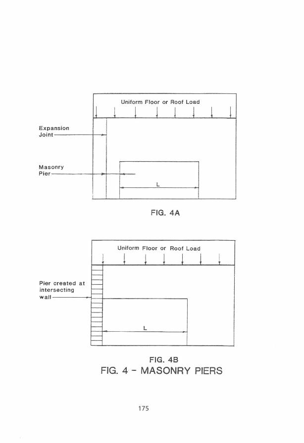
In some designs, expansion joints are placed near but not at the edge of the opening for architectural purposes (Figure 4A), or the beam occurs at a corner or perpendicular wall (Figure 4B) . In both cases, the pier created must be designed for the full vertical loading from the wall above. If the brick beam is designed for lintel action, the pier must also be designed for the lateralload developed by the arching of the wall loads over the beam. If the brick beam is not designed for Iintel action, there are no pier lateral loads developed by the wall above. Thus, the design of the pier is dependent upon architectural considerations and the choice of the structure type (lintel or beam) for the brick beam.
173

Expansion Joint
J
I I
I I
I I !
Uniform Floor or Roof Load
1 1 1 1 1 1 I ,
I \ / \
I \ B / \ ,.-"-, ------..-,
I P - ' " - ~' /concentrat~' ", :r:
I Load/ o" ~ I // 60 \ /'" ...I
;' :--:7 -í---'\~i45õ~,- - i L _ _ .... _ / _f _ '.t " -.J..---1---l'-
A E C 1 '- Brick
L I Beam
FIG. 2 - LINTEL ACTION
Uniform Floor or Roof Load
! p~ l 1 1 1 1 / \
/ \ \
\ , \ :r:
-f' Expansion 60°' Joint ,-t--- -- - - ...... "\----- -,
I I L
tBrick A C
L Beam !
FIG. 3 - BEAM ACTION
174
Exp Join
Mas Pier
ansioo t
onry
Pier created at intersecting
11 ! Uniform Floor or Roof Load
! ! J ! 1
L
FIG.4A
Uniform Floor or Roof Load
wall ------i---I-----------
L
FIG.48
FIG. 4 - MASONRY PIERS
175
!

3.2 Detailing/Specifications
There are several methods to detail a reinforced brick beam. The ungrauted option (Figure 5A) can only be used with a limited amount of reinforcing. The grouted option (Figure 58) is preferred for designs which require shear reinforcing and to provide a means to ancho r the bricks. Only the grouted option will be discussed.
i1-r-I I I I I I I I
~ I I I I I I
Grout
r~~ I
~I H'i~-i--+2 Bars CStirrups) I "'"'~~- Brick anchors I _...L.-_~~-IL.-L~"~~- Reinforcing L ~:;:ç~'---Reinforcing
FIG.5A
FIG.5
FIG.5B
REINFORCED BRICK BEAMS
Cored bricks are recommended for increased mechanical anchorage with the mortar and graut. In addition, cored bricks allow the designer to use reinforcing in the cores if desired. Anchorage to the graut is made with Z-shaped brick anchors or joint reinforcing. Some designers prefer to thread a reinforcing bar thraugh the brick cores which provides a more positive attachment but makes the beams more difficult to build.
For exterior walls, flashing and weeps above the beam are essential for cavity walls, and are also strongly recommended in solid walls to prevent water infiltration into the beam from the wall above. Roof overhangs on sloped roofs are important to limit the amount of water which washes the wall and could penetrate the wall. The concern here is to limit efflorescence of the wall and corrasion of the reinforcing.
The quality of the materiais used in the brick beams and wall should be strictly controlled. Bricks should be rated for severe weathering in harsh climates (ASTM C 216, Grade SW), and cored bricks are preferred. The initial rate of absorption (suction) should be Iimited to 30 gm/min/194 cm2 (30 gm/min/30 d) or less. Type
176

N or S mortar (ASTM C 270) is generally ali that is required for the beam eonstruetion. Tuek pointing mortar can be Type N. The grout is either fine or eoarse (ASTM C 476) depending upon the size of the eavity. Reinforeing is either bars or wires depending upon the type of beam selected.
Reinforeing and anehors in exterior walls should be eoated for eorrosion protection2
• Lastly, a high quality baeker rod and sealant along with weeps are needed to ereate dummy expansion joints Goints whieh appear as expansion joints, but whieh have grouted reinforeing passing through).
The specifications should require both a preconstruetion meeting and a test panel. The meeting should be to diseuss ali the masonry materiais and the methods to be used. Onee ali the material submittals are approved by the designer, the eontraetor should eonstruet a test panel which ineludes a brick beam. It is important that the test panel be constructed separate from the aetual project. It should be used as the standard of quality throughout the project to judge the workmanship. The actual construction should not proeeed until the quality of the test panel is aceeptable.
Another specification item is to require that ali the briek beams be built by the same masons who constructed the test panel. A limited number of masons building the brick beams results in better quality and also provides consistent attention to details.
3.3 Construction
As for the aetual construction, the formwork is simple; only shoring and bottom forms are required. The eonstruction of the wall above is not delayed by constructing the beam first; however, the amount of formwork shoring required is directly related to the construction sequence. If beams are first built and left to cure before the wall above is built, only reshores may be required .
Since the joints on the underside can not be tooled when the mortar is thumbprint hard, there are several methods available to tuckpoint the joints afterward. Some masons use a 13 em (0.5 in) thickness of sand between the brieks at the bottom of the beams. Others use a mixture of lime putty instead of sand, while others lay down a piece of sash cord for each joint. After the formwork is removed, the material in the joint bottom is removed and the joint is raked . Then, the joints are neatly tuck pointed. Prehydrating the tuek pointing mortar is required to minimize drying shrinkage.
Figure 6 shows a view of a completed beam in an insulated wall. Also included is a dummy expansion joint detail at the edge of the opening to provide crack control, but which still allows the reinforcing to be grouted through the joint.
177

11
1\
11
Expanslon joint above brick beam
11 11
11 II
" " a 11 E «I G)
Dl ~ o ;: Dl
Flashing .fuJl length of brick beam
Dummy joint at brick beam
=:::!~::::;;=:=:::!.l:~;:;=~~-p~~~-- Brick beam extends into pier
Edge of opening
Reinforcing --+--::
r Dummy joint . (rake joint & insta 11 backer rod & sealant)
continuous 1------------~------1 through joint in grout space
PLAN AT DUMMY JOINT
FIG.6 - STRUCTURAL BRICK BEAM
178

In comparison to steellintel beams, the brick beam design eliminates the expense of the steel. The cost of the masonry materiais, flashing, and weeps is nearly identical. The brick beams have the added cost of the formwork, and the labor to install reinforcing and to tuckpoint.
4. BRICK BEAMS IN A STRUCTURAL FRAME
4.1 Design
The second type of brick beam is less conventional and is used with steel beams to support the loads. Figure 7 has a steel beam with a plate on the bottom ftange to carry the weight of the masonry above. In this case, the steel beam carries the load and the brick beam is there primarily for appearance. However, the brick beam will attract some loads and must be reinforced accordingly.
EXTERIOR
Ins1Jlation--------~~I\l'II''_..
Metal studs & sheathing ---------
Flashing -------__
INTERIOR
Steel beam
5/16· Plate (notchedfor stirrups)
Weep holes Soft joint below plate Grout (backer rod & sealant)
Brick anchors ____ =lL--==~ijt~~~~--Stirrup hangers
mortared into cores of brick
1 Course of joint reinforcing
-FIG.? - BRICK BEAM
To determine howthese beams are designed, considerthe construction sequence. The masonry is first built above the steel beam which puts ali the dead load into the steel beam. Finally, the brick beam portion is constructed. Using this scenario, the stresses in the brick beam are developed only by loads which are superimposed after the brick beam is constructed plus its own weight.
179

The worst case loading on the brick beam would occur if the steel beam and the brick beam were tied rigidly together causing them to deflect the same. Therefore, the uniform superimposed load trom above (wuJ can be distributed to the to the steel (ws) and masonry (wm) whereby:
(1 )
(2)
Concentrated loads can similarly be distributed by the theory of consistent deflections.
For simplicity, the steel beam should be designed for the total load and the deflection due to live load limited to the span/600 or 7.5 mm (0.3 in), whichever is less. The masonry below the steel beam is designed as a structural brick beam using only wm •
4.2 Detailing/Specifications
Again looking at Figure 7, the construction above the steel plate is similar to when there is no brick beam below. The difterence is that the steel plate at the bottom of the steel beam is notched for the stirrup hangers, and the hangers are installed before the wall above is built. The hangers are installed loose. Flashing and weeps are very important.
The coursing of the bricks should be planned to allow a soft joint below the steel plate (same as the soft joint used below a relieving angle for a brick veneer on a multi-story building) . This allows the steel beam to deflect without loading the brick beam below. In this case, the weight of the brick beam can be relieved from the steel beam and transferred to the brick beam.
In the event the steel beam should load the brick beam by virtue of the soft joint being forgotten or incorrectly built, the reinforcing in the brick beam should be adequate using the design procedure previously outlined. Thus, the designer designs for the worst case loading but attempts to provide details which minimize the loading on the brick beam.
Dummy joints are again important to control cracking at the ends of the beam.
For the specifications, the materiais and construction concems are the same as outlined for the Structural Brick Beams.
180

4.3 Construction
As noted previously, the steel plate, beam, flashing, and weeps are essentially unchanged trom standard, steel lintel construction. The adqitional work involves the brick beam.
As with the Structural Brick Beams, the formwork here is sim pie. However, the grout placement requires greater care since the access is more limited. In Figure 7, the grout placement is made through the brick courses just below the steel plate which are initially left out. The grout should not be installed tight to the steel plate. The final brick course(s) are constructed after the graut is placed. As with the Structural Brick Beams, dummy joints at the edges of the opening are preferred.
The cost of building these brick beams is greater than simply using the steel beam and plate. However, using the techniques outlined, the additional cost to construct brick beams on a large project can be minoro The end result is the designer can create one of the most pleasing architectural features - brick beams.
5. REFERENCES
1. American Concrete Institute, American Society Of Civil Engineers, "Building Code Requirements for Masonry Structures", ACI 530-92/ASCE 5-92, New York, NY.
2. American Concrete Institute, American Society Of Civil Engineers, "Specifications for Masonry Structures", ACI 530.1-92/ASCE 6-92, New York, NY.
3. Beall, Christine, "Lintel Design and Detailing", Masonry Construction, March, 1993, pp. 106-110.
4. Brick Institute of America, "BIA Technical Notes on Brick Construction, Reinforced Brick Masonry, Flexural Design, Number 17A", Reston, VA.
5. Brick Institute of America, "BIA Technical Notes on Brick Construction, Reinforced Brick and Tile Lintels, Number 17H", Reston, VA.
181

182