design and construction of a small-scale rotorcraft uav system
TRANSCRIPT
ISSN: 2319-5967
ISO 9001:2008 Certified International Journal of Engineering Science and Innovative Technology (IJESIT)
Volume 3, Issue 1, January 2014
96
Abstract— A rotorcraft UAV is any flying machine that produces lift from rotors turning in a plane that is normally
close to the horizontal. The task of building a rotorcraft UAV platform for academic research may be daunting if the
enormous challenges and constraints associated with the research are considered. It involves design and construction of
the vehicle, and careful consideration of factors such as hardware components selection, layout design, desired range and
performance evaluation, among others. Although, there exist some commercial-of-the-shelf (COTS) platforms such as
Draganfly, Microdrones, Arducopter, etc., that can be easily adopted. However, it is difficult to find a platform that
effectively meets all the intended study requirements. Therefore, in such a situation, it becomes necessary to build a
platform that suits the research objectives. The design, construction and kitting of a rotorcraft UAV comprises the
following five key steps: (i) virtual design environment selection (ii) hardware components selection (iii) avionic system
design and integration (iv) vehicle design and construction (v) performance and reliability evaluation. This paper presents
a systematic design methodology for the construction of a small-scale rotorcraft UAV system.
Index Terms— Configurations, design and construction, performance, platform and small-scale rotorcraft UAV
system.
I. INTRODUCTION
There are an increasingly large number of laboratories and people in the academia working on the design and
development of rotorcraft UAV systems. It has been reported in [1] that existing remote control (RC) COTS
vehicles are used as research platforms by the majority of the academic researchers in order to fast track the
research work. The RC helicopters have experienced a rapid development during the last three decades due to the
increase in the number of professional hobby-purpose helicopter products and millions of aero-modeling fans.
Recently, there has been more interest in multiple-rotor RC flying vehicles, owing to their higher thrust-to-weight
ratio, reduced drag, stiffer rotors, and capability of performing many flight manoeuvre such as hovering and
loitering [2], thus making them prominent in the academic research circle. However, adopting a COTS vehicle has
its own shortcoming, as it may not meet some of the intended research requirements. Therefore, this study presents
a systematic approach towards building a small-scale rotorcraft UAV system that can be used as a platform for
academic research.
II. PLATFORM SELECTION
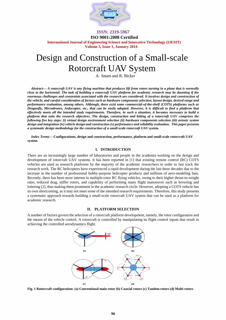
A number of factors govern the selection of a rotorcraft platform development, namely, the rotor configuration and
the means of the vehicle control. A rotorcraft is controlled by manipulating its flight control inputs that result in
achieving the controlled aerodynamics flight.
Fig. 1 Rotorcraft configuration: (a) Conventional main rotor (b) Coaxial rotors (c) Tandem rotors (d) Multi-rotors
Design and Construction of a Small-scale
Rotorcraft UAV System A. Imam and R. Bicker
ISSN: 2319-5967
ISO 9001:2008 Certified International Journal of Engineering Science and Innovative Technology (IJESIT)
Volume 3, Issue 1, January 2014
97
The changes made to the flight controls are transmitted to the rotor system, which in turn produce aerodynamic
effects on the vehicle's rotor blades, hence allowing an effective control of the vehicle. Regardless of rotorcraft
configuration, there are four basic achievable controls: roll, pitch, yaw and heave. The roll and pitch inputs control
the vehicle lateral and longitudinal motion, the yaw input controls the vehicle angular motion around the vertical
axis, and the heave input controls the vehicle motion along the vertical axis. The most common rotorcraft
configurations are conventional single main rotor, coaxial rotors, tandem rotor and multi-rotors as depicted
schematically in Fig 1.
A. Conventional main rotor (CMR) configuration
The conventional main rotor rotorcraft configuration (Fig. 1a), consists of a large main rotor rotating in a nominally
clockwise horizontal plane and a smaller tail rotor rotating in a nominally vertical plane parallel to the aircraft axis
to provide anti-torque. The main rotor is either articulated or rigid. There are three principle designs for main
rotors: rigid, semi-rigid (teetering), and fully articulated. Similarly, there are several designs for tail rotors:
conventional (which may be teetering, fully articulated, or rigid) and fan-in-fin having the added advantage of more
degree of safety for ground personnel and from obstacles while flying in confined areas. However, there are various
combinations of main and tail rotor types. For instance, the Enstrom line [3] uses a fully articulated main rotor and
a teetering tail; Robinson [4] and Bell [5] use teetering designs for both main and tail rotors. Some rotors turn
clockwise, and others counter clockwise. Similarly, tail rotors may turn one way or the other, or may be on either
side of the aircraft.
Regardless, the fundamental criteria for a conventional design are a relatively large lifting rotor and a smaller
device for reacting to the torque created by the larger rotor. Largely, the nature of the basic design defines how the
vehicle is controlled [6]. Control of the conventional rotorcraft is achieved by changing the pitch of the main and
tail rotor blades in various ways. This will then determine the amount of engine power needed. The rotors are
designed to turn at a constant speed, and the throttle setting need to be modified whenever the rotor power demand
changes in order to maintain constant speed.
B. Coaxial rotors (CAR) configuration
This design consists of two main rotor systems mounted on a common shaft, but rotating in opposite directions as
shown in Fig. 3.1(b), which removes the need for a tail rotor and makes the vehicle more compact. It uses the
residual torque due to angular speed difference between the two rotors to lift the vehicle vertically, or rotate it left
or right. Increasing or decreasing the angular speed of the rotors simultaneously permits climbing and descending.
The coaxial helicopter in hover behaves like a single rotor if the two rotors are not too far apart. However, if the
separation between the upper and lower rotor is significant, the lower rotor will encounter increased inflow velocity
and will require more power. Examples of this design are the Sikorsky ABC and the MIL-29.
C. Tandem rotors (TR) configuration
The tandem rotors configuration has two large main rotors, one in the front and one in the rear as depicted in Fig.
3.1(c). Example of vehicles under this configuration includes the Boeing CH-46 and 47. Because the rotors that are
widely separated provide lift of these aircraft, hence making the aircraft capable of lifting heavy loads across a wide
Centre-of-Gravity (CG_ range. Similarly, because both rotors are well away from the ground, personnel safety is
enhanced. The design mandates synchronization and high torque shafting between the rotors. The rotor system is
typically of the fully articulated design.
D. Multi-rotors (MR) configuration
Multi-rotor rotorcraft depicted in Fig. 3.1(d), are aerial vehicle with more than two rotors, they have fixed-pitch
blades rotors and are controlled by the differential thrust from the rotors pairs to change the thrust and torque.
Because of their ease of construction and control, they are frequently used in the model and radio control aircraft
projects. A multi-rotor rotorcraft has a minimum of three rotors, often each on different vertical axis. Most popular
in this design are Octocopter (eight rotors), e.g., Draganfly X8, Hexacopter (six rotors), e.g., MikroKopter and
Quadcopter or Quadrotor (four rotors), e.g., Parrot's “AR Drone”. The multi-rotors vehicles are now increasingly
being used as low-budget option commercial purposes such as aerial photography and videos of sites and
buildings, as well as in academic research [7].
ISSN: 2319-5967
ISO 9001:2008 Certified International Journal of Engineering Science and Innovative Technology (IJESIT)
Volume 3, Issue 1, January 2014
98
E. Platform configuration choice
In order to select a suitable rotorcraft configuration for this study, four different rotorcraft configurations described
in the previous subsections were compared in terms of key performance features and listed in Table 1. A grading
system between 1 and 5 was employed where Fair = 1, Average = 2, Good = 3, Very Good = 4 and Excellent = 5.
As previously stated, the multi-rotor vehicle has many variants defined by the number of rotors, with the least being
three. Therefore, to account for this, the four, six and eight rotors variants were considered for this comparison
where 4R = Quadrotor, 6R = Hexacopter and 8R = Octocopter. Table 1: Platform selection metrics
It can be deduced from Table 1, that the quadrotor turned out to be the platform of choice for this study. Unlike
other rotorcraft configurations, a quadrotor does not have any moving parts other than the four propellers. These
propellers are fixed pitch with a cross-pair spinning clockwise and the other pair counter clockwise. By precisely
regulating the propellers rotational speeds, all the common maneuvers of a standard rotorcraft are attainable.
III. HARDWARE COMPONENTS SELECTION
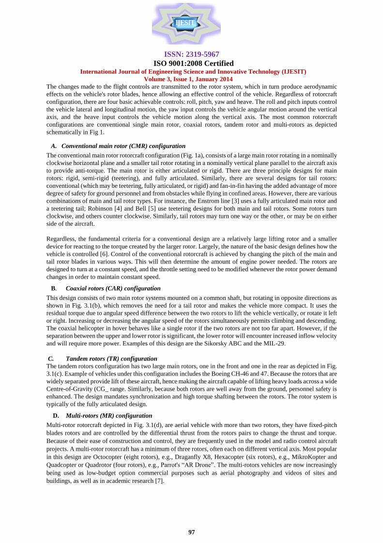
Figure 2 depicts the block diagram for the hardware configuration of the quadrotor, with devices represented by
solid blocks.
Fig. 2 Hardware configuration of Quadrotor UAV system
Feature CMR CAR TR 4R 6R 8R
Ease of development 1 2 3 5 4 3
Cost of development 2 4 4 4 3 2
Ease of control 1 2 2 4 3 2
Mechanical simplicity 1 2 3 4 3 2
Aerodynamic complexity 2 3 3 3 3 3
Maneuverability 2 4 3 4 4 4
Miniaturization 2 4 3 5 4 3
Survivability 3 3 3 3 3 3
Low speed flight 3 3 3 3 3 3
High speed flight 2 2 2 2 2 2
Power efficiency 5 5 4 4 2 2
Payload capability 2 2 3 4 5 5
Modularity 2 2 3 4 3 3
TOTAL 28 40 39 49 43 37
ISSN: 2319-5967
ISO 9001:2008 Certified International Journal of Engineering Science and Innovative Technology (IJESIT)
Volume 3, Issue 1, January 2014
99
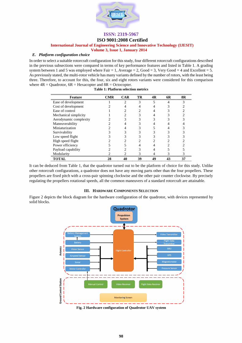
A. The vehicle platform (quadrotor)
The first item to be considered in the platform design is the quadrotor being the foundation upon which the rest of
the hardware components will be hosted. Again, after careful consideration of the research requirement, the
specifications listed in Table 2 have been decided for the quadrotor. Figure 3 illustrates the quadrotor virtual model
developed using SolidWorks software.
Table 2: Quadrotor key specifications
Serial Variable Specification
1 Dimension 0.44 x 0.44 x 0.045 m
2 No load weight 0.6 kg
3 Propeller type Fixed pitch
4 Rotor diameter 0.125 m
5 Payload capacity 1.8 kg
6 Frame material 3 mm Aluminum
7 Flight endurance 20 minutes
8 Drive type Brushless DC motor
9 Power source Lithium polymer battery
Fig. 3 Quadrotor virtual model
B. Propulsion system
The propulsion system consists of motors, batteries, electronic speed controllers (ESCs), and propellers. In
keeping with study objectives, 2 kg-force and 0.254 m were selected as the design thrust requirement from four
rotors and rotor diameter respectively, this also ensures the overall dimensions of the vehicle is within half meter
square.
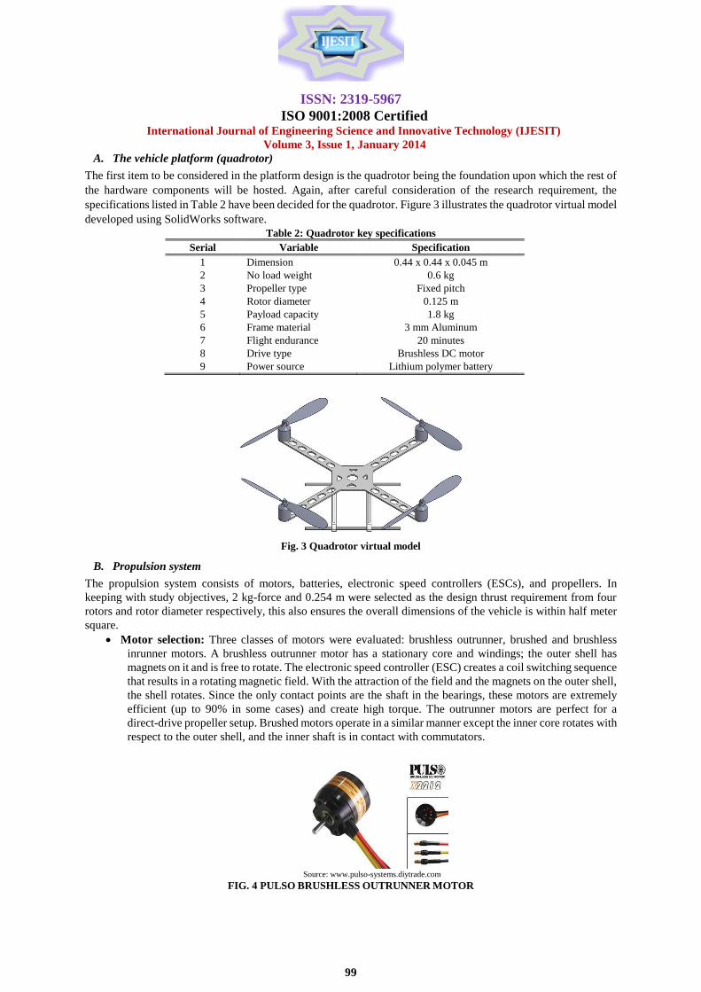
Motor selection: Three classes of motors were evaluated: brushless outrunner, brushed and brushless
inrunner motors. A brushless outrunner motor has a stationary core and windings; the outer shell has
magnets on it and is free to rotate. The electronic speed controller (ESC) creates a coil switching sequence
that results in a rotating magnetic field. With the attraction of the field and the magnets on the outer shell,
the shell rotates. Since the only contact points are the shaft in the bearings, these motors are extremely
efficient (up to 90% in some cases) and create high torque. The outrunner motors are perfect for a
direct-drive propeller setup. Brushed motors operate in a similar manner except the inner core rotates with
respect to the outer shell, and the inner shaft is in contact with commutators.
Source: www.pulso-systems.diytrade.com
FIG. 4 PULSO BRUSHLESS OUTRUNNER MOTOR
ISSN: 2319-5967
ISO 9001:2008 Certified International Journal of Engineering Science and Innovative Technology (IJESIT)
Volume 3, Issue 1, January 2014
100
These motors are inherently less efficient due to friction and provide less torque than a brushless outrunner
provides. The inrunner motors are used to operate small propellers at high rates of speed, or in a geared propeller
system. Premise to the above, the choice of PULSO series 2212 brushless out runner motor (Fig. 4) was made [8].
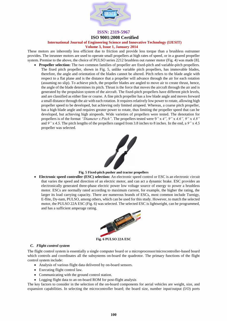
Propeller selection: The two common families of propeller are fixed-pitch and variable-pitch propellers.
The fixed pitch propeller, shown in Fig. 5, unlike variable pitch propellers, has immovable blades,
therefore, the angle and orientation of the blades cannot be altered. Pitch refers to the blade angle with
respect to a flat plane and is the distance that a propeller will advance through the air for each rotation
(assuming no slip). To achieve pitch, the propeller blades are angled to move air to create thrust, hence,
the angle of the blade determines its pitch. Thrust is the force that moves the aircraft through the air and is
generated by the propulsion system of the aircraft. The fixed-pitch propellers have different pitch levels,
and are classified as either fine or coarse. A fine pitch propeller has a low blade angle and moves forward
a small distance through the air with each rotation. It requires relatively low power to rotate, allowing high
propeller speed to be developed, but achieving only limited airspeed. Whereas, a coarse pitch propeller,
has a high blade angle and requires greater power to rotate, thus limiting the propeller speed that can be
developed, but achieving high airspeeds. Wide varieties of propellers were tested. The denotation for
propellers is of the format “Diameter x Pitch”. The propellers tested were 9” x 4”, 9” x 4.6”, 9” x 4.8”
and 9” x 4.5. The pitch lengths of the propellers ranged from 3.8 inches to 8 inches. In the end, a 9” x 4.5
propeller was selected.
Fig. 5 Fixed-pitch pusher and tractor propellers
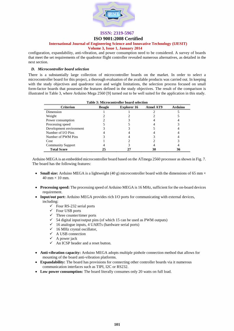
Electronic speed controller (ESC) selection: An electronic speed control or ESC is an electronic circuit
that varies the speed and direction of an electric motor, and can act a dynamic brake. ESC provides an
electronically generated three-phase electric power low voltage source of energy to power a brushless
motor. ESCs are normally rated according to maximum current, for example, the higher the rating, the
larger its load carrying capacity. There are numerous brands of ESCs, most common include Turnigy,
E-flite, Dy-nam, PULSO, among others, which can be used for this study. However, to match the selected
motor, the PULSO 22A ESC (Fig. 6) was selected. The selected ESC is lightweight, can be programmed,
and has a sufficient amperage rating.
Fig. 6 PULSO 22A ESC
C. Flight control system
The flight control system is essentially a single computer board or a microprocessor/microcontroller-based board
which controls and coordinates all the subsystems on-board the quadrotor. The primary functions of the flight
control system include:
Analysis of various flight data delivered by on-board sensors.
Executing flight control law.
Communicating with the ground control station.
Logging flight data to an on-board ROM for post-flight analysis
The key factors to consider in the selection of the on-board components for aerial vehicles are weight, size, and
expansion capabilities. In selecting the microcontroller board; the board size, number input/output (I/O) ports
ISSN: 2319-5967
ISO 9001:2008 Certified International Journal of Engineering Science and Innovative Technology (IJESIT)
Volume 3, Issue 1, January 2014
101
configuration, expandability, anti-vibration, and power consumption need to be considered. A survey of boards
that meet the set requirements of the quadrotor flight controller revealed numerous alternatives, as detailed in the
next section.
D. Microcontroller board selection
There is a substantially large collection of microcontroller boards on the market. In order to select a
microcontroller board for this project, a thorough evaluation of the available products was carried out. In keeping
with the study objectives and quadrotor size and weight limitations, the selection process focused on small
form-factor boards that possessed the features defined in the study objectives. The result of the comparison is
illustrated in Table 3, where Arduino Mega 2560 [9] turned out to be well suited for the application in this study.
Table 3: Microcontroller board selection
Criterion Beagle Explorer 16 Atmel AT9 Arduino
Dimension 1 1 2 5
Weight 2 2 2 5
Power consumption 2 3 4 4
Processing speed 5 5 4 3
Development environment 3 3 5 4
Number of I/O Pins 4 4 4 4
Number of PWM Pins 3 4 3 4
Cost 1 2 2 3
Community Support 4 3 4 4
Total Score 25 27 30 36
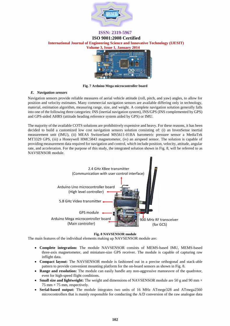
Arduino MEGA is an embedded microcontroller board based on the ATmega 2560 processor as shown in Fig. 7.
The board has the following features:
Small size: Arduino MEGA is a lightweight (40 g) microcontroller board with the dimensions of 65 mm ×
40 mm × 10 mm.
Processing speed: The processing speed of Arduino MEGA is 16 MHz, sufficient for the on-board devices
requirement.
Input/out port: Arduino MEGA provides rich I/O ports for communicating with external devices,
including:
Four RS-232 serial ports
Four USB ports
Three counter/timer ports
54 digital input/output pins (of which 15 can be used as PWM outputs)
16 analogue inputs, 4 UARTs (hardware serial ports)
16 MHz crystal oscillator,
A USB connection
A power jack
An ICSP header and a reset button.
Anti-vibration capacity: Arduino MEGA adopts multiple pinhole connection method that allows for
mounting of the board anti-vibration platforms.
Expandability: The board has provisions for connecting other controller boards via it numerous
communication interfaces such as TIPI, I2C or RS232.
Low power consumption: The board literally consumes only 20 watts on full load.
ISSN: 2319-5967
ISO 9001:2008 Certified International Journal of Engineering Science and Innovative Technology (IJESIT)
Volume 3, Issue 1, January 2014
102
Fig. 7 Arduino Mega microcontroller board
E. Navigation sensors
Navigation sensors provide reliable measures of aerial vehicle attitude (roll, pitch, and yaw) angles, to allow for
position and velocity estimates. Many commercial navigation sensors are available differing only in technology,
material, estimation algorithm, measuring range, size, and weight. A complete navigation solution generally falls
into one of the following three categories: INS (inertial navigation system), INS/GPS (INS complemented by GPS)
and GPS-aided AHRS (attitude heading reference system aided by GPS) or IMU.
The majority of the available COTS solutions are prohibitively expensive and heavy. For these reasons, it has been
decided to build a customized low cost navigation sensors solution consisting of: (i) an InvenSense inertial
measurement unit (IMU), (ii) MEAS Switzerland MS5611-01BA barometric pressure sensor a MediaTek
MT3329 GPS, (iii) a Honeywell HMC5843 magnetometer, (iv) an airspeed sensor. The solution is capable of
providing measurement data required for navigation and control, which include position, velocity, attitude, angular
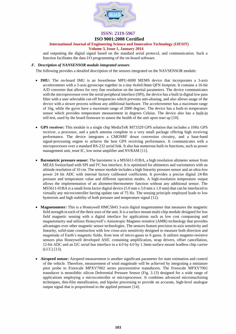
rate, and acceleration. For the purpose of this study, the integrated solution shown in Fig. 8, will be referred to as
NAVSENSOR module.
Fig. 8 NAVSENSOR module
The main features of the individual elements making up NAVSENSOR module are:
Complete integration: The module NAVSENSOR consists of MEMS-based IMU, MEMS-based
three-axis magnetometer, and miniature-size GPS receiver. The module is capable of capturing raw
inflight data.
Compact layout: The NAVSENSOR module is fashioned out in a precise orthogonal and stack-able
pattern to provide convenient mounting platform for the on-board sensors as shown in Fig. 8.
Range and resolution: The module can easily handle any non-aggressive manoeuvre of the quadrotor,
even for high-speed flight conditions.
Small size and lightweight: The weight and dimensions of NAVSENSOR module are 50 g and 90 mm ×
75 mm × 75 mm, respectively.
Serial-based output: The module integrates two units of 16 MHz ATmege328 and ATmega2560
microcontrollers that is mainly responsible for conducting the A/D conversion of the raw analogue data
ISSN: 2319-5967
ISO 9001:2008 Certified International Journal of Engineering Science and Innovative Technology (IJESIT)
Volume 3, Issue 1, January 2014
103
and outputting the digital signal based on the standard serial protocol, and communication. Such a
function facilitates the data I/O programming of the on-board software.
F. Description of NANSENSOR module integrated sensors
The following provides a detailed description of the sensors integrated on the NAVSENSOR module:
IMU: The on-board IMU is an InvenSense MPU-6000 MEMS device that incorporates a 3-axis
accelerometer with a 3-axis gyroscope together in a tiny 4x4x0.9mm QFN footprint. It contains a 16-bit
A/D converter that allows for very fine resolution on the inertial parameters. The device communicates
with the microprocessor over the serial peripheral interface (SPI), the device has a built in digital low pass
filter with a user selectable cut-off frequencies which prevents anti-aliasing, and also allows usage of the
device with a slower process without any additional hardware. The accelerometer has a maximum range
of 16g, while the gyros have a maximum range of 2000 deg/sec. The device has a built-in temperature
sensor which provides temperature measurement in degrees Celsius. The device also has a built-in
self-test, used by the board firmware to assess the health of the unit upon start up [10].
GPS receiver: This module is a single chip MediaTeK MT3329 GPS solution that includes a 10Hz GPS
receiver, a processor, and a patch antenna complete in a very small package offering high receiving
performance. The device integrates a CMOSRF down conversion circuitry, and a base-band
signal-processing engine to achieve the best GPS receiving performance. It communicates with a
microprocessor over a standard RS-232 serial link. It also has numerous built-in functions, such as power
management unit, reset IC, low noise amplifier and NVRAM [11].
Barometric pressure sensor: The barometer is a MS5611-01BA, a high resolution altimeter sensor from
MEAS Switzerland with SPI and I²C bus interface. It is optimized for altimeters and variometers with an
altitude resolution of 10 cm. The sensor module includes a high linearity pressure sensor and an ultra-low
power 24 bit ADC with internal factory calibrated coefficients. It provides a precise digital 24-Bit
pressure and temperature value and different operation modes. A high-resolution temperature output
allows the implementation of an altimeter/thermometer function without any additional sensor. The
MS5611-01BA is a small form factor digital device (5.0 mm x 3.0 mm x 1.0 mm) that can be interfaced to
virtually any microcontroller having update rate of 75 Hz. The sensing principle employed leads to low
hysteresis and high stability of both pressure and temperature signal [12).
Magnetometer: This is a Honeywell HMC5843 3-axis digital magnetometer that measures the magnetic
field strength in each of the three axes of the unit. It is a surface mount multi-chip module designed for low
field magnetic sensing with a digital interface for applications such as low cost compassing and
magnetometry and utilizes Honeywell‟s Anisotropic Magneto resistive (AMR) technology that provides
advantages over other magnetic sensor technologies. The sensors feature precision in-axis sensitivity and
linearity, solid-state construction with low cross-axis sensitivity designed to measure both direction and
magnitude of Earth‟s magnetic fields, from tens of micro-gauss to 6 gauss. It utilizes magneto-resistive
sensors plus Honeywell developed ASIC containing amplification, strap drivers, offset cancellation,
12-bit ADC and an I2C serial bus interface in a 4.0 by 4.0 by 1.3mm surface mount leadless chip carrier
(LCC) [13).
Airspeed sensor: Airspeed measurement is another significant parameter for state estimation and control
of the vehicle. Therefore, measurement of wind magnitude will be achieved by integrating a miniature
pitot probe to Freescale MPXV7002 series piezoresistive transducers. The Freescale MPXV7002
transducer is monolithic silicon Deferential Pressure Sensor (Fig. 3.13) designed for a wide range of
applications employing a microcontroller or microprocessor. It combines advanced micromachining
techniques, thin-film metallization, and bipolar processing to provide an accurate, high-level analogue
output signal that is proportional to the applied pressure [14].
ISSN: 2319-5967
ISO 9001:2008 Certified International Journal of Engineering Science and Innovative Technology (IJESIT)
Volume 3, Issue 1, January 2014
104
G. Peripheral sensors
The peripheral sensors are not part of the NAVSENSOR module, but complement the vehicle‟s navigation and
surveillance capabilities, thus making up the vehicle‟s avionic system. They are mounted to the vehicle‟s frame.
Sonar sensor: The GPS unit and barometric sensor of the NAVSENSOR module are capable of providing
acceptable height measurement with accuracy of about 2 m and only accurate at high altitudes. To
improve navigation robustness, additional small size and lightweight ultrasonic sonar, namely, a Mabotix
EZ0 [15), was integrated for measuring the vertical height at lower altitudes. The sensor's effective range
is 6 m with a resolution in the millimeter level. The output of the sensor is voltage signal (0 to 5 V
corresponding to 0 to 6.45 m), which is input to an analogue input channel of the flight controller.
Vision sensor: The vision camera is responsible for obtaining inflight visual information on the
surrounding environment. The camera choice was a compact-size GoPro Hero full HD camera [16]. The
camera has the following features:
Video resolutions up to 4K
12MP photos up to 30 frames per second
Built-in Wi-Fi
SuperView™ and Auto Low Light modes
Waterproof up to 40 m
Designed for FPV and shields in transparent plastic housing
Compact size and weight 58g
146 degrees wide view angle
Can be remotely controlled
H. Wireless RF communication
A pair of radio frequency (RF) transceiver is mostly used communications between aerial vehicles and ground
control stations. Inflight status down link, video transmission and command/trajectory uploading are both
done through this wireless system. Factors considered for the selection of the RF modules were
communication range and reliability. However, to avoid interference, three transmission frequency bands
were chosen for the wireless transmission of the vehicle's inflight data and commands. The selected bands
are: (i) 900MHz for inflight data transmission/trajectory uploading, (ii) 5.8GHz for video transmission and
(iii) 2.4GHz for manual control transmission and autonomous mode switching. Detailed description of the
communication links for data and telemetry transmission on the quadrotor are given below:
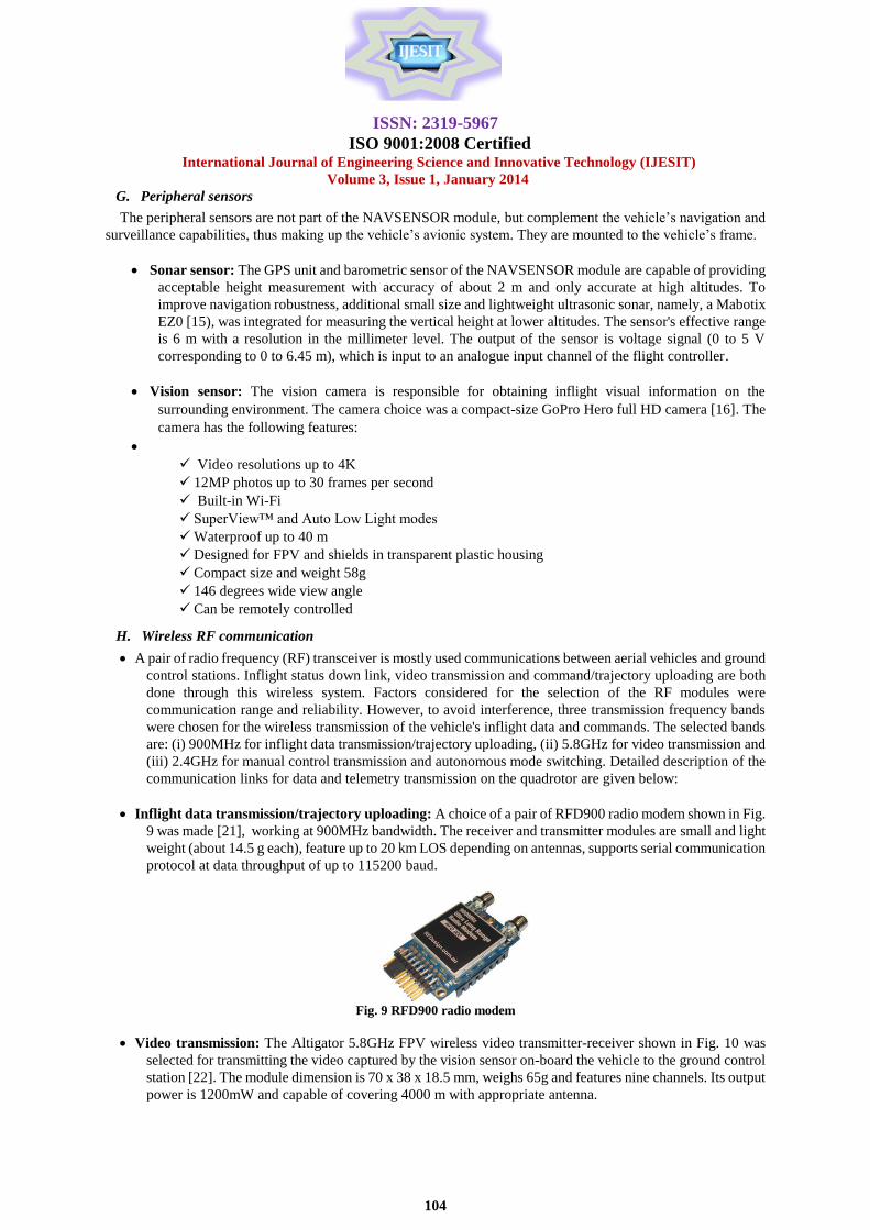
Inflight data transmission/trajectory uploading: A choice of a pair of RFD900 radio modem shown in Fig.
9 was made [21], working at 900MHz bandwidth. The receiver and transmitter modules are small and light
weight (about 14.5 g each), feature up to 20 km LOS depending on antennas, supports serial communication
protocol at data throughput of up to 115200 baud.
Fig. 9 RFD900 radio modem
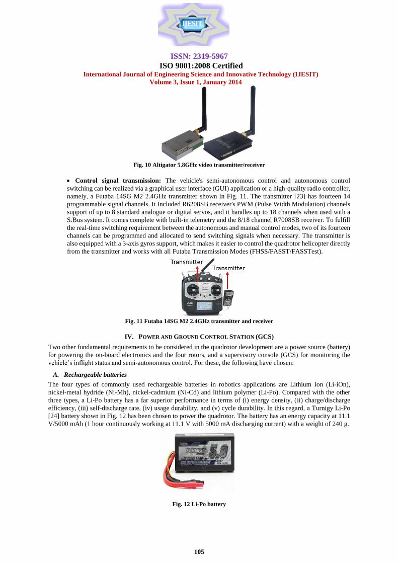
Video transmission: The Altigator 5.8GHz FPV wireless video transmitter-receiver shown in Fig. 10 was
selected for transmitting the video captured by the vision sensor on-board the vehicle to the ground control
station [22]. The module dimension is 70 x 38 x 18.5 mm, weighs 65g and features nine channels. Its output
power is 1200mW and capable of covering 4000 m with appropriate antenna.
ISSN: 2319-5967
ISO 9001:2008 Certified International Journal of Engineering Science and Innovative Technology (IJESIT)
Volume 3, Issue 1, January 2014
105
Fig. 10 Altigator 5.8GHz video transmitter/receiver
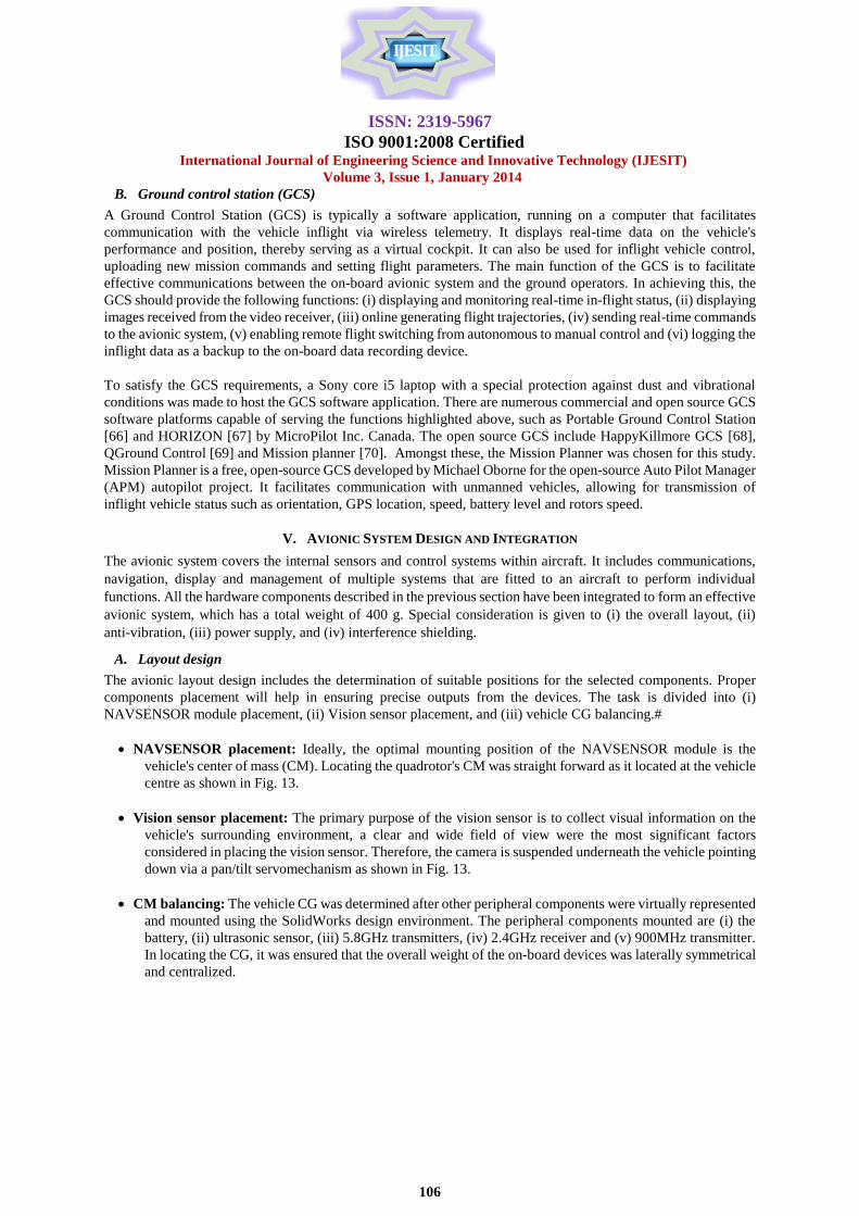
Control signal transmission: The vehicle's semi-autonomous control and autonomous control
switching can be realized via a graphical user interface (GUI) application or a high-quality radio controller,
namely, a Futaba 14SG M2 2.4GHz transmitter shown in Fig. 11. The transmitter [23] has fourteen 14
programmable signal channels. It Included R6208SB receiver's PWM (Pulse Width Modulation) channels
support of up to 8 standard analogue or digital servos, and it handles up to 18 channels when used with a
S.Bus system. It comes complete with built-in telemetry and the 8/18 channel R7008SB receiver. To fulfill
the real-time switching requirement between the autonomous and manual control modes, two of its fourteen
channels can be programmed and allocated to send switching signals when necessary. The transmitter is
also equipped with a 3-axis gyros support, which makes it easier to control the quadrotor helicopter directly
from the transmitter and works with all Futaba Transmission Modes (FHSS/FASST/FASSTest).
Fig. 11 Futaba 14SG M2 2.4GHz transmitter and receiver
IV. POWER AND GROUND CONTROL STATION (GCS)
Two other fundamental requirements to be considered in the quadrotor development are a power source (battery)
for powering the on-board electronics and the four rotors, and a supervisory console (GCS) for monitoring the
vehicle‟s inflight status and semi-autonomous control. For these, the following have chosen:
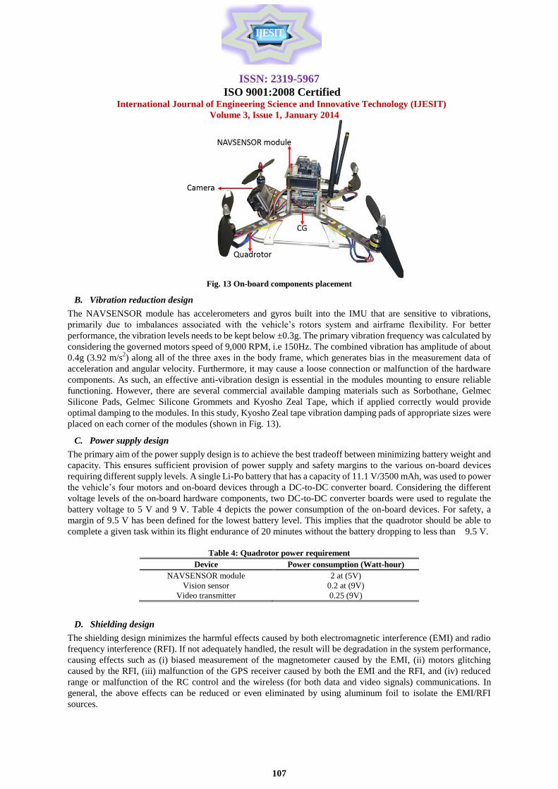
A. Rechargeable batteries
The four types of commonly used rechargeable batteries in robotics applications are Lithium Ion (Li-iOn),
nickel-metal hydride (Ni-Mh), nickel-cadmium (Ni-Cd) and lithium polymer (Li-Po). Compared with the other
three types, a Li-Po battery has a far superior performance in terms of (i) energy density, (ii) charge/discharge
efficiency, (iii) self-discharge rate, (iv) usage durability, and (v) cycle durability. In this regard, a Turnigy Li-Po
[24] battery shown in Fig. 12 has been chosen to power the quadrotor. The battery has an energy capacity at 11.1
V/5000 mAh (1 hour continuously working at 11.1 V with 5000 mA discharging current) with a weight of 240 g.
Fig. 12 Li-Po battery
ISSN: 2319-5967
ISO 9001:2008 Certified International Journal of Engineering Science and Innovative Technology (IJESIT)
Volume 3, Issue 1, January 2014
106
B. Ground control station (GCS)
A Ground Control Station (GCS) is typically a software application, running on a computer that facilitates
communication with the vehicle inflight via wireless telemetry. It displays real-time data on the vehicle's
performance and position, thereby serving as a virtual cockpit. It can also be used for inflight vehicle control,
uploading new mission commands and setting flight parameters. The main function of the GCS is to facilitate
effective communications between the on-board avionic system and the ground operators. In achieving this, the
GCS should provide the following functions: (i) displaying and monitoring real-time in-flight status, (ii) displaying
images received from the video receiver, (iii) online generating flight trajectories, (iv) sending real-time commands
to the avionic system, (v) enabling remote flight switching from autonomous to manual control and (vi) logging the
inflight data as a backup to the on-board data recording device.
To satisfy the GCS requirements, a Sony core i5 laptop with a special protection against dust and vibrational
conditions was made to host the GCS software application. There are numerous commercial and open source GCS
software platforms capable of serving the functions highlighted above, such as Portable Ground Control Station
[66] and HORIZON [67] by MicroPilot Inc. Canada. The open source GCS include HappyKillmore GCS [68],
QGround Control [69] and Mission planner [70]. Amongst these, the Mission Planner was chosen for this study.
Mission Planner is a free, open-source GCS developed by Michael Oborne for the open-source Auto Pilot Manager
(APM) autopilot project. It facilitates communication with unmanned vehicles, allowing for transmission of
inflight vehicle status such as orientation, GPS location, speed, battery level and rotors speed.
V. AVIONIC SYSTEM DESIGN AND INTEGRATION
The avionic system covers the internal sensors and control systems within aircraft. It includes communications,
navigation, display and management of multiple systems that are fitted to an aircraft to perform individual
functions. All the hardware components described in the previous section have been integrated to form an effective
avionic system, which has a total weight of 400 g. Special consideration is given to (i) the overall layout, (ii)
anti-vibration, (iii) power supply, and (iv) interference shielding.
A. Layout design
The avionic layout design includes the determination of suitable positions for the selected components. Proper
components placement will help in ensuring precise outputs from the devices. The task is divided into (i)
NAVSENSOR module placement, (ii) Vision sensor placement, and (iii) vehicle CG balancing.#
NAVSENSOR placement: Ideally, the optimal mounting position of the NAVSENSOR module is the
vehicle's center of mass (CM). Locating the quadrotor's CM was straight forward as it located at the vehicle
centre as shown in Fig. 13.
Vision sensor placement: The primary purpose of the vision sensor is to collect visual information on the
vehicle's surrounding environment, a clear and wide field of view were the most significant factors
considered in placing the vision sensor. Therefore, the camera is suspended underneath the vehicle pointing
down via a pan/tilt servomechanism as shown in Fig. 13.
CM balancing: The vehicle CG was determined after other peripheral components were virtually represented
and mounted using the SolidWorks design environment. The peripheral components mounted are (i) the
battery, (ii) ultrasonic sensor, (iii) 5.8GHz transmitters, (iv) 2.4GHz receiver and (v) 900MHz transmitter.
In locating the CG, it was ensured that the overall weight of the on-board devices was laterally symmetrical
and centralized.
ISSN: 2319-5967
ISO 9001:2008 Certified International Journal of Engineering Science and Innovative Technology (IJESIT)
Volume 3, Issue 1, January 2014
107
Fig. 13 On-board components placement
B. Vibration reduction design
The NAVSENSOR module has accelerometers and gyros built into the IMU that are sensitive to vibrations,
primarily due to imbalances associated with the vehicle‟s rotors system and airframe flexibility. For better
performance, the vibration levels needs to be kept below ±0.3g. The primary vibration frequency was calculated by
considering the governed motors speed of 9,000 RPM, i.e 150Hz. The combined vibration has amplitude of about
0.4g (3.92 m/s2) along all of the three axes in the body frame, which generates bias in the measurement data of
acceleration and angular velocity. Furthermore, it may cause a loose connection or malfunction of the hardware
components. As such, an effective anti-vibration design is essential in the modules mounting to ensure reliable
functioning. However, there are several commercial available damping materials such as Sorbothane, Gelmec
Silicone Pads, Gelmec Silicone Grommets and Kyosho Zeal Tape, which if applied correctly would provide
optimal damping to the modules. In this study, Kyosho Zeal tape vibration damping pads of appropriate sizes were
placed on each corner of the modules (shown in Fig. 13).
C. Power supply design
The primary aim of the power supply design is to achieve the best tradeoff between minimizing battery weight and
capacity. This ensures sufficient provision of power supply and safety margins to the various on-board devices
requiring different supply levels. A single Li-Po battery that has a capacity of 11.1 V/3500 mAh, was used to power
the vehicle‟s four motors and on-board devices through a DC-to-DC converter board. Considering the different
voltage levels of the on-board hardware components, two DC-to-DC converter boards were used to regulate the
battery voltage to 5 V and 9 V. Table 4 depicts the power consumption of the on-board devices. For safety, a
margin of 9.5 V has been defined for the lowest battery level. This implies that the quadrotor should be able to
complete a given task within its flight endurance of 20 minutes without the battery dropping to less than 9.5 V.
Table 4: Quadrotor power requirement
Device Power consumption (Watt-hour)
NAVSENSOR module 2 at (5V)
Vision sensor 0.2 at (9V)
Video transmitter 0.25 (9V)
D. Shielding design
The shielding design minimizes the harmful effects caused by both electromagnetic interference (EMI) and radio
frequency interference (RFI). If not adequately handled, the result will be degradation in the system performance,
causing effects such as (i) biased measurement of the magnetometer caused by the EMI, (ii) motors glitching
caused by the RFI, (iii) malfunction of the GPS receiver caused by both the EMI and the RFI, and (iv) reduced
range or malfunction of the RC control and the wireless (for both data and video signals) communications. In
general, the above effects can be reduced or even eliminated by using aluminum foil to isolate the EMI/RFI
sources.
ISSN: 2319-5967
ISO 9001:2008 Certified International Journal of Engineering Science and Innovative Technology (IJESIT)
Volume 3, Issue 1, January 2014
108
VI. PERFORMANCE EVALUATION
To evaluate the performance and reliability of the quadrotor system, four ground tests were conducted. The
experiment involved (i) RC range check, (ii) Wireless communication reliability check, (iii) Battery discharge rate
and (iv) Vibration check. The experiments results show acceptable performances of the vehicle in the test
categories. During the tests, the vehicle was placed on level ground 100m away from the GCS with its throttle set
at 65% equivalent of 5,000-RPM rotors speed.
A. Range check
The range check evaluates the wireless RF communication ranges of the 900MHz, 2.4GHz and 5.8GHz as well as
interference tendency. This is essential for both manual and autonomous control modes. It has been verified during
the intensive ground tests that at 1000 m radius mission range, the three wireless RF modules signal strengths were
excellent. Again, there was no interference between the different frequency bands. A feat attributed to the EMI/RFI
shielding design.
B. Wireless communication reliability check
The wireless communications reliability between the quadrotor and GCS was verified by continuously transmitting
the inflight data packages at 100 Hz. The test has proven that the communication between the vehicle and GCS was
robust within 1000 m with no interference with other frequency bands.
C. Battery management
Having defined the battery safety discharge level of 9.5 V, to ascertain the reliability of the power supply design, a
test has been conducted to determine the battery discharge rate and establish if it is within the safety margin. During
the test, the vehicle was run for 25 minutes non-stop and the battery discharge rate was recorded. The result was
compared with the battery rated discharge rate, the output voltages of the curves dropped but with reasonable
slopes where the final values were 10.42 and 10.10 V. Besides close agreement between the experiment and rated
battery discharge rate, the final battery voltage is within the safety level. This result indicates that the selected
battery has sufficient power to supply the overall quadrotor system.
D. Vibration check
To evaluate the vehicle vibration suppression, four tests were conducted to ascertain the vibration level at most
critical locations of the vehicle. The locations are the extreme ends of the vehicle's arms and the CG. During the
tests, three-axis vibration-detection sensors were mounted at each of these locations. The result shows a
vibration-transmitting rate in the range of 10%–15%, which indicates that the anti-vibration design was remarkably
effective, but the sensitivity to vibration can be attenuated through appropriate software filtering.
VII. CONCLUSION
This paper has presented detailed requirements for the design, construction and kitting-out of a small-scale
rotorcraft UAV, namely a quadrotor. A quadrotor is a small responsive four-rotor vehicle controlled by the
rotational speed of its rotors. It is compact in design with the ability to carry a high payload. Topics discussed
include platform selection which ensures appropriate choice of vehicle configuration; selection of virtual design
environment for the modeling of the selected vehicle; hardware components selection which ensures right choice
sensors and associated electronic for the vehicle; design of the avionic system which involves proper arrangement
of sensors and electronic components to ensure compatibility, vibration reduction, battery power management and
shielding design to minimize the harmful effects caused by both electromagnetic interference (EMI) and radio
frequency interference (RFI). More so, the performance of the quadrotor has also been evaluated in terms of RF
range check, wireless communication reliability check, battery discharge rate and vibration check to ensure
conformity to the set performance requirements. The study has laid a foundation for further research on small-scale
rotorcraft UAVs, specifically in the area of flight control system design, which involves derivation of the vehicle
dynamic model and aerodynamic analysis. Therefore, the future work for this study will involve mathematical
modelling and aerodynamic analysis of the quadrotor as a precursor to the vehicle system identification and
eventual design of the vehicle‟s flight control system. The aim of the aerodynamics analysis will be to establish the
effect of wind disturbance on the vehicle when used in an outdoor environment, with the overall objective of
accounting for the wind disturbance effect in the design of an autonomous flight control system for the vehicle.
ISSN: 2319-5967
ISO 9001:2008 Certified International Journal of Engineering Science and Innovative Technology (IJESIT)
Volume 3, Issue 1, January 2014
109
REFERENCES [1] A. S. Imam and R. Bicker, “Significant of Wind Disturbance on a Quadrotor Helicopter in Hover Flight”, sixth European
Conference on Mobile Robots (ECMR'13), Barcelona Spain, Sept 25 to Sept 27, 2013.
[2] C. Guowei, L. Feng, B. M. Chen and T. H. Lee, "Development of fully functional miniature unmanned rotorcraft
systems", in „proceedings of the 29th Chinese Control Conference (CCC), 2010‟, pp 32 -40, 2010.
[3] Enstrom Helicopter Corporation, "Piston Helicopter Pilot Training Guide", (2006).
[4] Robinson Helicopter, "Robinson Maintenance Manual", (2013).
[5] Bell Helicopter, "Bell 206L4 Product Specification", (2013).
[6] S. George, "X-Plane Pilot's Operating Handbook", (2001).
[7] R. Leishman, J. Macdonald, T. McLain, and R. Beard, "Relative navigation and control of a hexacopter", in „proceedings
of the Robotics and Automation (ICRA), 2012‟, pp 4937-4942, 2002.
[8] PULSO Systems, "PUOLSO motors", http://www.pulsosystem.com/u22l-870.html, (2013).
[9] Arduino, "Arduino Mega 2560", http://arduino.cc/en/Main/ArduinoBoardMega2560, (2013).
[10] InvenSence, "MPU-6000 MEMS IMU”, http://invensense.com/mems/gyro/mpu6000.html, (2013).
[11] 3D-Robotics, "MediaTek - MT3329 GPS", http://store.3drobotics.com/products/mediatekmt3329- gps-v2-0, (2013).
[12] CSG-Shop, "MS5611 BAROMETRIC PRESSURE SENSOR VARIOMETER",
http://www.csgshop.com/product.php?id-product=24, (2013).
[13] Digi-Key Corporation., "Honeywell 3-Axis Digital Compass IC - HMC5843",
http://www.digikey.com/product/honeywell-hmc/530, (2013).
[14] Freescale Semiconductor, "MPXV7002 Differential and Gauge Pressure Sensor", Datasheet, (2009).
[15] MaxBotix, "LV-MaxSonar-EZ0", http://www.maxbotix.com/documents/MB1000- Datasheet.pdf, (2013).
[16] HERO3+ Black Edition, http://gopro.com/cameras/hd-hero3-black-edition, (2013).
[17] Portable Ground Control Station Datasheet V2.1, http://www.robotshop.com/media/files/PDF/datasheet-stand-gcs.pdf,
(2013).
[18] HORIZON Ground Control Station, http://www.micropilot.com/products-horizonmp.htm, (2013).
[19] Mather, P., "Happy Killmore Ground Control Station", http://code.google.com/p/ardupilot-mega/wiki/HappyKillmore,
(2013).
[20] Meier, L., "QGround Control Station", http://www.qgroundcontrol.org/, (2010).
[21] D. Oborne, M., "Mission Planner Ground Control Station", http://code.google.com/p/ardupilot-mega/wiki/Mission,
(2013).
[22] RFD900 Radio Modem, http://www.rfddesign.com.au/index.php/rfd900, (2014).
[23] Altigator 5.8GHz FPV wireless video RF, http://mikrokopter.altigator.com, (2014).
[24] Futaba 14SG M2 2.4GHz transmitter and receiver, http://www.futaba-rc.com/, (2014).
[25] Turnigy Li-Po Battery,
http://www.hobbyking.co.uk/hobbyking/store/__9518__Turnigy_5000mAh_6S_30C_Lipo_Pack.html, (2014).