design and build of a 50w thermacoustic generator2
TRANSCRIPT

Design and build of a 50W thermacoustic generator(2).docx 1 / 18
On the design of near atmospheric air operated thermoacoustic engines
Blue print for a simple, reliable and low cost heat driven thermoacoustic generators for rural areas producing 20-50W electric power.
Author: Kees de Blok Date: December 2013 The thermoacoustic generator (TAG) described in this report is a results of joint activities carried out in the framework of the Score project (www.score.uk.com) carried out in the UK, the FACT Foundation (www.fact-foundation.com) and Aster Thermoacoustics ( www.aster-thermoacoustics.com ) in the Netherlands. Conversion of heat (from primary energy sources) into a higher form of energy, like mechanical power or electricity, is one of the oldest and most wide spread underlying technologies supporting nearly all our modern infrastructure, communication and social activities which in their turn are recognized as essential ingredients for prosperity. Therefore, The availability of devices for small scale conversion of heat into electricity could contribute to the improvement of living conditions in rural areas and developing countries. Thermoacoustics is a novel energy conversion technology in which the compression, expansion and displacement of the working gas is driven by acoustic wave motion rather than by pistons, valves and displacers. While the physics behind is rather complex the final implementation is simple which allows for low production, investment and maintenance costs. Today, thermoacoustics is a fast emerging technology aimed for the conversion of low and medium temperature waste or solar heat into cold or electricity both on domestic and industrial scale. Due to the scalability, final simplicity and low cost, thermoacoustics is also a candidate as small scale conversion technology for rural and developing areas. This was recognized few years ago in, for example, the Score project in England and by initiatives supported by the FACT Foundation in the Netherlands The aim of these projects, is to develop low cost thermoacoustic devices generating electricity for lightning, charging mobile phones etc. combined with wood stoves for cooking or heating water. These projects also address the social and economic aspects involving charities and local communities. On short term this type of devices could contribute to improving local living conditions by the use of small scale air operated multipurpose devices for preparing hot water, cooking and generating some electricity. It could also stimulated labour related to local production installation and maintenance of these devices. In time, on national level this technology could improve prosperity by generating labour on product development, production and maintenance of more high end thermoacoustic energy conversion systems and give them a lead by utilizing the most recent developments in, for example, solar powered cooling avoiding excessive (future) electricity consumption and reducing environmental issues. The aim of this report1 is to provide interested individuals, communities or universities with the physics and practical issues of such near atmospheric pressure operated thermoacoustic generators. We hope this will stimulate further work on these devices and finally to local production and markets.
1 Document history Version Date Notes 1.0 September 2013 1.1 December 2013 Introduction page added

Design and build of a 50W thermacoustic generator(2).docx 2 / 18
Content 1 General design considerations ............................................................................................................. 4
1.1 Working gas ................................................................................................................................. 4 1.2 Mean pressure ............................................................................................................................. 4 1.3 Heat transfer to and from the TA process ...................................................................................... 4 1.4 Number of engine stages .............................................................................................................. 4 1.5 Conversion of acoustic power into electricity ................................................................................. 5
2 Construction ......................................................................................................................................... 6 2.1 High temperature input section ..................................................................................................... 6 2.2 Heat exchangers .......................................................................................................................... 7 2.3 Regenerators ................................................................................................................................ 8 2.4 Thermal buffer tube ...................................................................................................................... 9 2.5 Assembled 2-stage engine...........................................................................................................10 2.6 Acoustic load and conversion to electricity ...................................................................................10 2.7 Acoustic feedback and resonance circuit .....................................................................................11
3 Performance .......................................................................................................................................13 3.1 Measurement setup .....................................................................................................................13 3.2 Effect of mean pressure ...............................................................................................................13 3.3 Electric output power ...................................................................................................................14
4 Production Cost...................................................................................................................................16 4.1 Options for further cost reduction .................................................................................................16
5 Conclusions and recommendations .....................................................................................................18 Introduction Conversion of heat (from primary energy sources) into a higher form of energy, like mechanical power or electricity, is one of the oldest and most wide spread underlying technologies supporting nearly all our modern infrastructure, communication and social activities which in their turn are recognized as essential ingredients for prosperity. Therefore, small scale conversion of heat into electricity could contribute to the improvement of living conditions in rural areas and developing countries. In general, devices converting heat into mechanical power, propulsion, cold or electricity make use of rotary, linear moving and sliding mechanical parts. In particular, when these parts are operated at high temperatures and pressures associated with the thermodynamic cycle (e.g. combustion) there will arise some constrains in life time cost and maintenance. Thermoacoustics is a conversion technology in which the compression, expansion and displacement of the working gas is driven by acoustic wave motion rather than by pistons, valves and displacers. Using acoustic wave motion eliminates mechanical friction and wear and therefore drastically increase lifespan and minimize maintenance. Because of the lack of moving mechanical parts in the thermodynamic process the construction tolerances and material requirements are relaxed allowing for (potential) low production and investment costs. These specific properties makes thermoacoustics also a candidate for low cost, small scale conversion technology for rural and developing areas.

Design and build of a 50W thermacoustic generator(2).docx 3 / 18
These opportunities were recognized in, for example, the Score project in England and by initiatives supported by the FACT Foundation in the Netherlands. The aim of these projects started a few years ago is to develop low cost thermoacoustic devices generating electricity for lightning, charging mobile phones etc. combined with wood stoves for cooking or heating water. These projects also address the social and economic aspects involving charities and local communities. On short term this type of devices could contribute to improving local living conditions by the use of small scale air operated multipurpose devices for preparing hot water, cooking and generating some electricity. It could also stimulated labour related to local production installation and maintenance of these devices. In time, on national level this technology could improve prosperity by generating labour on product development, production and maintenance of more high end thermoacoustic energy conversion systems and give them a lead by utilizing the most recent developments in, for example, solar powered cooling avoiding excessive (future) electricity consumption and reducing environmental issues. One of the applications to start with, is to combine heating of water with the generation of some electricity by inserting a thermoacoustic generator between the (wood) fire and the water to be heated. This is depicted schematically in Figure 1.
Figure 1 Principle and a previous demonstrator (build Nov. 2012) of the combined water boiler and thermoacoustic generator (TAG)
In this configuration heat is supplied to the high temperature side (dome) of the TAG by direct contact with the fire. In order to maintain a temperature difference, to drive the thermoacoustic cycle in the TAG, part of low temperature heat exchangers are immersed in the water reservoir rejecting their heat by natural convection and contribute also to the heating2 of the water. It should be noted however that this is only one of the applications. In fact, near atmospheric thermoacoustic generators are generic devices which can be deployed in any other application in which a few hundred degrees of temperature difference is available between arbitrary heat sinks and heat sources. This document describes the design approach and underlying physics of a pre-production version of a small scale near atmospheric near air operated thermoacoustic generators and will provide a blueprint for the further (local) development and production of such generators in and for rural areas and developing countries. The layout of this report is as follows. Chapter 2 will address the general design approach and underlying physics and explains the choice of the various components taking into account the practical and economic constrains in this field of applications. In Chapter 3 the various components are described and specified in more detail together with the assembled 2-stage engine. Chapter 4 presents the measurements and characterization of the TAG. Chapter 5 finalizes with the conclusions and also the recommended follow up activities.
2 Note that water temperature cannot exceed 100°C at atmospheric pressure. Typically the water will be heated up to 60-70°C

Design and build of a 50W thermacoustic generator(2).docx 4 / 18
1 General design considerations Thermoacoustic engines using air at (near) atmospheric pressure has the prospect to be low cost and simple devices for converting heat into electricity for rural areas. While the final embodiment is simple, the design and optimization of air operated thermoacoustic devices however has turned out to be even more complicated as the design of high end thermoacoustic3. Therefore this section will address the design approach and choice of the various design parameters in more detail.
1.1 Working gas The underlying thermodynamic cycle in thermoacoustics is close to the Carnot cycle and in theory therefore independent of the gas type. In practice helium at high mean pressure is the preferred medium because of the high heat conductance and γ value and the low characteristic acoustic impedance (ρ.c). Unless helium is the preferred gas, cost and availability inhibits its use in rural areas. As an alternative atmospheric or compressed air can be used. With air as working gas efficiency and power density are lower than for helium but the advantage for rural areas is evident.
1.2 Mean pressure Thermal and acoustic power levels are proportional with density of the working gas and from that proportional with mean pressure. Thermoacoustic engines can run with air at atmospheric pressure. In that case however static heat losses dominate and acoustic boundary layer losses are high as compared to the acoustic power producing relatively large systems with low output power. This all rapidly improves at increasing mean pressure (P0). At the same drive ratio the acoustic power will raise proportional P0 while the acoustic losses in the feedback or resonance circuit raise with only P0
0.5. and static heat losses hardly increase. This dramatically improves the efficiency and allows for extracting more acoustic (= electric) output power at the same thermal input heat and temperature. The improvement in ratio between acoustic loop power and acoustic loss is most obvious when doubling the mean pressure from 100 kPa (atmospheric) up to 200 kPa. On the other hand, at (too) high mean pressure, constructive requirements become an issue in terms of cost and safety. So for this application a mean pressure of 200-300 kPa will be a compromise. Practical considerations are, that at these values the system can be pressurized using a hand pump and that for the acoustic feedback circuit standard PVC tubing or thin walled metal tubing can be used in order to reduce weight and cost.
1.3 Heat transfer to and from the TA process To run the thermoacoustic engine, heat has to supplied at high temperature and removed at low temperature from the engine internal heat exchangers.. For small scale thermoacoustic generators a water or thermal oil circuit using circulation pumps is no option and passive4 means of heat transfer like natural convection, heat pipes or radiation need to be used instead.
1.4 Number of engine stages An important design parameter is the ratio between acoustic loop power and acoustic output power. The net (acoustic) output power is always a fraction of the acoustic loop power depending only on the available temperature difference. For single stage TA engines typically the acoustic loop power is found to be more than 5 times the acoustic output which implies that 50W net acoustic output power requires more than 250 W acoustic loop power to be generated and maintained in the acoustic feedback or resonator circuit. For a fixed input temperature difference, the only way to increase loop gain is to connect a second engine stage in series. In that case acoustic output power remains the same but loop power is halved which is beneficial for a number of reasons.
3 using helium at high mean pressure 4 no mechanical moving parts
Design and build of a 50W thermacoustic generator(2).docx 5 / 18
High acoustic loop power not only result in high acoustic losses (relative to the net output power) but such a high loop power could be a also source of external vibration which in unwanted in a living environment. As said, acoustic losses are proportional with acoustic loop power so it is beneficial to reduce loop power by increase the (thermo)acoustic loop gain by a series connection of multiple engine stages. This approach is successfully demonstrated in the European THATEA project and the SBIR TAP project resulting in onset and operating temperature differences less than 30°C respectively 150°C between the heat exchanger in- and output circuits. Multiple stages however increase the number of components, cost and complexity. Small scale near atmospheric pressure air operated thermoacoustic generators are intent to run at temperatures in the order of 300-500°C. For this temperature range a compromise is the use of two stages. This already improves performance significantly because of it halves the magnitude of the acoustic loop power associated losses and vibration issues. The two engine stages can be combined in different ways. They can be separated and coupled by acoustically matched traveling wave sections or placed close together yielding a single unit as is described in this document.
1.5 Conversion of acoustic power into electricity For temperatures exceeding the onset temperature the surplus on acoustic power can be extracted as useful output power from the acoustic resonance of feedback circuit and dissipated into an acoustic load. This load could be a second TA system generating a temperature lift (heat pump or cooler) or an acoustic to electric converter. Such an converter could be a dedicated linear alternator, loudspeaker (used in reverse) or a bi-directional turbine. The last one is a recent development converting the periodic velocity into rotation and from there into electricity using a normal generator. This concept is under development yet but the prospect is that cost of converting acoustic power into electricity can be reduced by at least one order of magnitude as compared to linear alternators and can be scaled unlimited to any power level. In the small scale generator described in this document a standard loudspeaker is used as an intermediate low cost solution. In time this component will be replaced by a production version of a low cost bi-directional turbine plus generator. Summarizing, the preferred configuration of a TAG for this application includes
• Two-stage thermoacoustic engine
• Air at 1 to 2 barg (200-300kPa) as working gas.
• Heat supply to a dome in direct contact with the fire
• Heat rejection by natural convection to a water reservoir
• Acoustic circuit build from standard high pressure (PN10) PVC tubing
• Conversion of acoustic power into electricity by a standard loudspeaker
Design and build of a 50W thermacoustic generator(2).docx 6 / 18
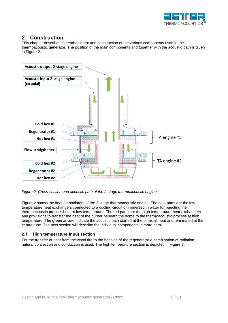
2 Construction This chapter describes the embodiment and construction of the various components used in the thermoacoustic generator. The position of the main components and together with the acoustic path is given in Figure 2.
Figure 2 Cross-section and acoustic path of the 2-stage thermoacoustic engine
Figure 2 shows the final embodiment of the 2-stage thermoacoustic engine. The blue parts are the low temperature heat exchangers connected to a cooling circuit or immersed in water for rejecting the thermoacoustic process heat at low temperature. The red parts are the high temperature heat exchangers and provisions to transfer the heat of the burner beneath the dome to the thermoacoustic process at high temperature. The green arrows indicate the acoustic path started at the co-axial input and terminated at the centre tube. The next section will describe the individual components in more detail.
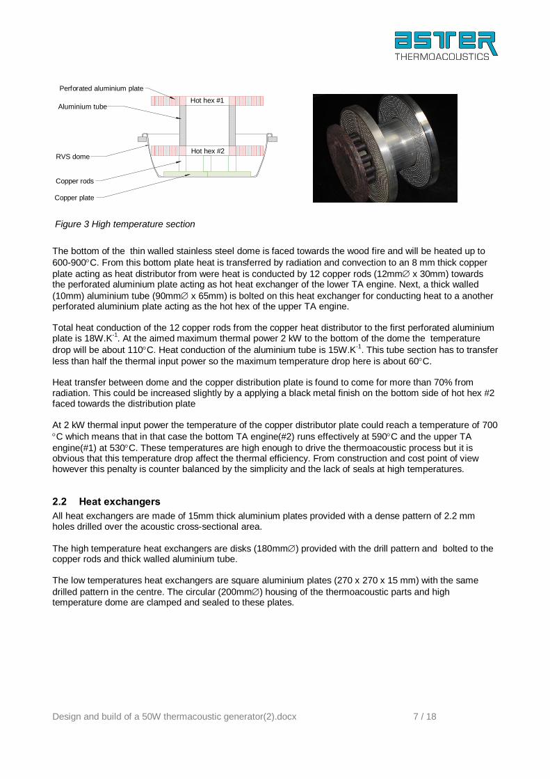
2.1 High temperature input section For the transfer of heat from the wood fire to the hot side of the regenerator a combination of radiation, natural convection and conduction is used. The high temperature section is depicted in Figure 3.
Design and build of a 50W thermacoustic generator(2).docx 7 / 18
Copper rods
Copper plate
Aluminium tube
Perforated aluminium plate
RVS dome
Hot hex #1
Hot hex #2
Figure 3 High temperature section
The bottom of the thin walled stainless steel dome is faced towards the wood fire and will be heated up to 600-900°C. From this bottom plate heat is transferred by radiation and convection to an 8 mm thick copper plate acting as heat distributor from were heat is conducted by 12 copper rods (12mm∅ x 30mm) towards the perforated aluminium plate acting as hot heat exchanger of the lower TA engine. Next, a thick walled (10mm) aluminium tube (90mm∅ x 65mm) is bolted on this heat exchanger for conducting heat to a another perforated aluminium plate acting as the hot hex of the upper TA engine. Total heat conduction of the 12 copper rods from the copper heat distributor to the first perforated aluminium plate is 18W.K-1. At the aimed maximum thermal power 2 kW to the bottom of the dome the temperature drop will be about 110°C. Heat conduction of the aluminium tube is 15W.K-1. This tube section has to transfer less than half the thermal input power so the maximum temperature drop here is about 60°C. Heat transfer between dome and the copper distribution plate is found to come for more than 70% from radiation. This could be increased slightly by a applying a black metal finish on the bottom side of hot hex #2 faced towards the distribution plate At 2 kW thermal input power the temperature of the copper distributor plate could reach a temperature of 700 °C which means that in that case the bottom TA engine(#2) runs effectively at 590°C and the upper TA engine(#1) at 530°C. These temperatures are high enough to drive the thermoacoustic process but it is obvious that this temperature drop affect the thermal efficiency. From construction and cost point of view however this penalty is counter balanced by the simplicity and the lack of seals at high temperatures.
2.2 Heat exchangers All heat exchangers are made of 15mm thick aluminium plates provided with a dense pattern of 2.2 mm holes drilled over the acoustic cross-sectional area. The high temperature heat exchangers are disks (180mm∅) provided with the drill pattern and bolted to the copper rods and thick walled aluminium tube. The low temperatures heat exchangers are square aluminium plates (270 x 270 x 15 mm) with the same drilled pattern in the centre. The circular (200mm∅) housing of the thermoacoustic parts and high temperature dome are clamped and sealed to these plates.

Design and build of a 50W thermacoustic generator(2).docx 8 / 18
Figure 4 Perforated plate cold and hot heat exchangers
In the final setup the parts of these square plates protruding the circular housing are immersed in the water allowing heat rejection of the thermoacoustic process by natural convection. For testing purposes these plates are provide also with water channels allowing them to be connected to a water circulation circuit for measuring the cold hex thermal powers. The thermal power for the thermoacoustic process is taken from or supplied to the heat exchangers grid more or less uniform distributed over the regenerator cross-sectional area. For the hot hex however heat is supplied from the centre while for the cold hex heat is removed at the rim. This all produce a radial temperature distribution as is shown in Figure 5
Figure 5 Radial temperature distribution hot hex when heated from the centre and the effect of acoustic loop
power on the hex temperatures
The calculated and measured (thermocouples) radial temperature difference between centre and rim agrees well and is found to be in the order of 15°C. Figure 5 also shows how acoustic loop power modifies the hex temperatures and radial distribution.
2.3 Regenerators Commonly used regenerator material is woven stainless steel mesh. The regular structure and the large range of wire diameters and mesh sizes commercial available has made this the default regenerator material for thermoacoustics. Cost of this mesh however is high and cutting sheets in shape (disk, ring) further increase the cost up to a level contrary with the aimed concept.

Design and build of a 50W thermacoustic generator(2).docx 9 / 18
As an alternative regenerators could be made of the finest grade (00) of stainless steel wool5. Cost is only a fraction of the cost for stainless steel mesh and can be easily shaped. An additional advantage is that static heat conduction per cm2 is significant less because of the random structure and higher volume porosity. In particular for near atmospheric air operated thermoacoustic devices this is a relevant feature because reduced heat loss more than counter balance the small penalty (2-3%) in thermoacoustic efficiency.
Figure 6 Regenerator made of stainless steel wool placed in a rim glued on the cold hex plate
The ring shaped6 regenerator for the lower TA engine (#2) is made of 135 grams fine (00) stainless steel wool filling the 25mm space between the hot and cold heat exchanger. The regenerator for the upper TA engine (#1) is adapted to the somewhat lower power and operating temperature for this stage and is made of 90 gram fine (00) stainless steel wool filling the 15mm space between hot and cold hex.
2.4 Thermal buffer tube The open space between the hot hex and the acoustic circuit (or optional ambient hex), often called “thermal buffer tube” , is assumed to provide thermal isolation between the hot hex and the other components. In practice this is hard to realize and without some precautions a significant heat loss could occurs via this buffer tube. For engine #2 the length (≈600 mm) of thin walled tube in the centre is adequate to minimize heat losses which is confirmed by the fact that temperature of this tube at the top of the system remains below 50°C when in operation. A more critical situation exist in the open space between the hot hex of #1 and the cold hex of #2. The mutual distance between them (buffer tube length) is only 30 mm. While the acoustic gas displacement even at maximum power is smaller than this distance, excessive cold hex heat flow of #2, exceeding 10 times the acoustic loop power, is observed when oscillation started. After disassembling it was found that flow resistance over the regenerator cross-sectional area was not uniform resulting in severe jet streaming. A new made, more uniform, regenerator yield an improvement but heat loss was still high.
5 Ordinary steel wool can be used only at temperatures below 200°C because of rapid oxidation (or even combustion) at higher temperatures 6 Produced by wrapping a string of steel wool between two plates up to the desired diameter

Design and build of a 50W thermacoustic generator(2).docx 10 / 18
Finally a flow straightener made form 30PPI nickel foam is inserted halfway the space between the #2 hot hex and #1 cold hex solved the problem largely. This flow straightener is depicted in Figure 7.
Figure 7 Flow straightener in the “thermal buffer section” between #1 hot hex and #2 cold hex
Cold hex heat flow now is reduced down to about 3 times the acoustic loop power which is close to the expected value based on the use of air and the regenerator ωτ values. This result endorses the importance of minimizing the acoustic flow induced heat loss by forcing the flow to be uniform across the regenerator cross-sectional area which is a common issue for all (high temperature) thermoacoustic engines and coolers
2.5 Assembled 2-stage engine The assemble 2-stage engine is shown in Figure 8.
Figure 8 Assembled engine
The dome of the engine is intend to be placed in a hole in the bottom water reservoir allowing direct contact with the wood fire. The rectangular aluminium plates protruding the circular housing will be in contact with the water inside the reservoir and will release their heat by natural convection. Due to the co-axial embodiment the acoustic output is at the top and the acoustic input at the side made by a PVC T-junction. The acoustic circuit is described in the next chapter.
2.6 Acoustic load and conversion to electricity Dedicated linear alternators used in high end applications are too expensive for use in this kind of low cost generators. Therefore, part of the acoustic loop power generated by the 2-stage engine is converted into

Design and build of a 50W thermacoustic generator(2).docx 11 / 18
electricity by using a standard woofer (JL-Audio type 6w3v3-8). This speaker has a high Qt value and a stiff and small diameter cone. The allowable excursion of the cone is more than 15 mm p-p. Acoustic impedance matching between a thermoacoustic engine and acoustic load is essential in order to get the system oscillating and to get useful output power. In order to quantify the acoustic load the impedance of the speaker is measured as a function of the electric load resistor (Re). The result is plotted in Figure 9
Figure 9 Measured complex impedance of the speaker as a function of electric load resistor
Figure 9 shows that the acoustic impedance is strongly coupled to the electric load resistor which indicate a reasonable efficiency. It also shows that the free air resonance frequency (complex term ⇒ 0) is around 45 Hz which means that at 60 Hz the impedance is also positive complex (≈ + i0.7.ρ.c). The measured efficiency of this speaker defined as electric power dissipated over the load resistor over acoustic power dissipated by the cone is more than 50% in the frequency range from 40-90Hz.
2.7 Acoustic feedback and resonance circuit The 2-stage thermoacoustic engine act as a heat driven acoustic power amplifier with a gain proportional with the temperature difference applied. To make this amplifier oscillate an acoustic resonance or feedback circuit between acoustic output and input is required. This feedback circuit also include the acoustic to electric converter (e.g. loudspeaker) or other load to the system. In this, the impedance of the acoustic load is an essential part of the resonance and feedback circuit and therefore its (complex) impedance should be taken into account in design. For the current embodiment the acoustic load is coupled close to the co-axial input of the 2-stage engine as is depicted in Figure 10.
20 30 40 50 60 70 80 90 1000
0.2
0.4
0.6
0.8
1
1.2
1.4
1.6
1.8
2
freq [Hz]
real
(Z) /
ρ.c
JL-Adio 6W3v3-8, D0= 68mm
Re = 0 Ω
Re = 3 Ω
Re = 8 Ω
Re = 18 Ω
Re = 39 Ω
Re = 102 Ω
Re = inf
20 30 40 50 60 70 80 90 100-2
-1.5
-1
-0.5
0
0.5
1
1.5
2
2.5
freq [Hz]
imag
(Z) /
ρ.c
JL-Adio 6W3v3-8, D0= 68mm
Re = 0 Ω
Re = 3 Ω
Re = 8 Ω
Re = 18 Ω
Re = 39 Ω
Re = 102 Ω
Re = inf

Design and build of a 50W thermacoustic generator(2).docx 12 / 18
Figure 10 2-stage engine with integrated acoustic load and the in- and output terminals to the acoustic feedback circuit
The configuration shown in Figure 10 has the advantage is that it yield an integrated engine – converter unit which can be coupled to an arbitrary passive feedback circuit folded and shaped to fit to the available space. For the current implementation the acoustic feedback circuit is assembled from standard tubes and bends made from high pressure PVC tubing (PN10) glued together to produce a gas tight feedback circuit. The acoustic in- and output of the 2-stage engine are provide with detachable connections allowing the PVC feedback circuit to be removed for modification or transport. The actual length and geometry of the feedback circuit depends on the acoustic load. In particular when a loudspeaker is used off-resonance, its remaining inertance need to be considered as part of the acoustic timing circuit. Combined with the JL-Audio speaker the distance to the acoustic geometry look like Figure 11.
Figure 11 PVC acoustic feedback circuit(partially folded) attached to the in-and output terminals of the 2-stage TA engine
The JL-Audio speaker is mounted in the enlarged volume (160mm∅ x 160mm length) at the engine input located close to the first cold hex. Further, all regular tubing is made from 75mm∅ PVC tubing except for the matching volume shown at the top. This volume placed at a distance of about λ/10 from the engine hot hex and is essential for matching the TA engine in- and output impedance to the feedback loop. It is made from a 125mm∅ x 200 mm PVC tube, clamped between two diameter transition sections (75∅mm ⇒ 125 mm∅) Optionally, the feedback tubes may be spiralled or folded as long as the acoustic length of each section is maintained.

Design and build of a 50W thermacoustic generator(2).docx 13 / 18
3 Performance This section gives the measured performance of the prototype
3.1 Measurement setup The complete system is placed on a flat plate with a controllable gas burner beneath. At the position of the burner the plate has a 200mm∅ hole to fit in the dome of the engine. This plate shield also the other parts of the system to the burner heat and actually it simulated the bottom of the water tank in which the generator will be mounted in the end.
Figure 12 Test setup
For the test the low temperature heat exchangers (square plates) are connected in series to a water circuit. Temperature and water flow rate of this circuit are measured enabling for measuring the cold hex thermal powers. A dpdx probe is installed on the wall of the feedback circuit for real time measuring acoustic loop power. In addition a pressure sensor is available at the cold hex of the first engine stage Temperature of the heat exchangers is measured using K-type thermocouples positioned in the middle of the drill pattern of each heat exchanger.
3.2 Effect of mean pressure As pointed out in chapter 2 mean pressure has a significant effect on the performance. This is illustrated in Figure 13 showing the acoustic loop power and hot hex temperature as a function of mean pressure measured at minimum burner power.

Design and build of a 50W thermacoustic generator(2).docx 14 / 18
Figure 13 Acoustic loop power and hot hex temperature of engine #2
Figure 13 shows that acoustic loop power and with that the acoustic output power drastically increase with mean power. At the same time the hot hex temperature declines indication less acoustic losses. Saturation of the curve above 170kPa in Figure 13 is due to the increasing acoustic mismatch between engine and loudspeaker. This is because the characteristic impedance of the gas (ρ.c) is proportional with mean pressure while the acoustic impedance of the speaker remains constant. This is a common issue for all linear alternators used off-resonance. Therefore the acoustic circuit need to be matched to the impedance of the alternator or loudspeaker at the design mean pressure. In the TAG this is done by increasing the length of the matching volume. Consequently the performance at atmospheric pressure drops but the optimum is reached now at 200 kPa mean pressure.
3.3 Electric output power After optimizing the TAG for operation at 200 kPa the electric output power of the TAG is measured as a function of the hot hex temperature of the engine #2. The result is shown in Figure 14.
Figure 14 Acoustic and electric output power versus the hot hex temperature of engine stage #2 for air
at 200 kPa as working gas

Design and build of a 50W thermacoustic generator(2).docx 15 / 18
Figure 14 shows that the onset temperature of the TAG is about 140°C and that at a hot hex temperature of 330°C the net acoustic output power exceeds 50W. The efficiency of the loudspeaker used for the conversion of this acoustic power into electricity is 41% so an electric output of about 22W is available. Note that this electric output is not limited by the thermoacoustic part but is limited by the maximum acoustic power (stroke) the speaker can handle without affecting durability too much. The measured data in Figure 14 suggest that for the current embodiment, operating with air at 200 kPa (2 barg) as working gas, 50W electric output power is within reach if the efficiency of the acoustic to electric converter could be increased up to 70% and the hot hex temperature to about 370°C. As shown in Figure 14, the net acoustic output power is about 52W at a hot hex temperature of 330°C. the net thermal input7 at this point is in the order of 1 kW which yield an thermal efficiency of 5% which is typical for such a simple near atmospheric air operated thermoacoustic device. However, due to the modest efficiency of the loudspeaker the overall conversion from heat to electricity is only 2%. In the current embodiment a limitation in heat transfer between the heat source and dome is observed due to its relatively small outer surface. In order to increase the heat transfer to the thermoacoustic process, fins or a more advance flow of the combustion gas through or around the dome is needed. The current implementation the TAG however shows that with simple materials an operable device can be build which can be deployed as it is but can be used also as base for further (local) development of this kind of applications.
7 Estimated from burner power and cold hex heat flow
Design and build of a 50W thermacoustic generator(2).docx 16 / 18
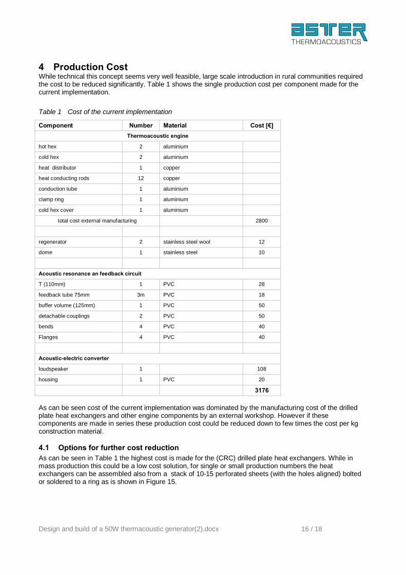
4 Production Cost While technical this concept seems very well feasible, large scale introduction in rural communities required the cost to be reduced significantly. Table 1 shows the single production cost per component made for the current implementation.
Table 1 Cost of the current implementation
Component Number Material Cost [€] Thermoacoustic engine
hot hex 2 aluminium
cold hex 2 aluminium
heat distributor 1 copper
heat conducting rods 12 copper
conduction tube 1 aluminium
clamp ring 1 aluminium
cold hex cover 1 aluminium
total cost external manufacturing 2800
regenerator 2 stainless steel wool 12
dome 1 stainless steel 10
Acoustic resonance an feedback circuit
T (110mm) 1 PVC 28
feedback tube 75mm 3m PVC 18
buffer volume (125mm) 1 PVC 50
detachable couplings 2 PVC 50
bends 4 PVC 40
Flanges 4 PVC 40
Acoustic-electric converter
loudspeaker 1 108
housing 1 PVC 20
3176 As can be seen cost of the current implementation was dominated by the manufacturing cost of the drilled plate heat exchangers and other engine components by an external workshop. However if these components are made in series these production cost could be reduced down to few times the cost per kg construction material.
4.1 Options for further cost reduction As can be seen in Table 1 the highest cost is made for the (CRC) drilled plate heat exchangers. While in mass production this could be a low cost solution, for single or small production numbers the heat exchangers can be assembled also from a stack of 10-15 perforated sheets (with the holes aligned) bolted or soldered to a ring as is shown in Figure 15.

Design and build of a 50W thermacoustic generator(2).docx 17 / 18
Figure 15 Stack of ten, 1.2 mm thick aluminium perforated sheets with 2mm∅ holes (aligned) replacing
the CRC drilled plate
In order to optimize thermal conduction between sheets and ring the mutual distance between the M3 bolts should be no more than 30 mm. Based on the retail price for perforated aluminium sheets cost will be about € 30 per heat exchanger. Cost for the PVC tubing in Table 1 are retail prices. Ordering large quantities will further reduce these cost For the conversion of acoustic power into electricity loudspeakers are not the preferred choice because of their weight and low efficiency. A recent development on small bi-directional turbines combined with low a cost (mass produced) rotary generator will further reduce the cost of the acoustic to electric conversion because these turbines can be made in plastic moulding for less than € 20. It is essential to spread the heat from the dome to the regenerator surface however the copper heat distributor used in this prototype contribute significant to cost and weight and slow down the response to the heat source. So finding an alternative way to get heat from the dome into the regenerator is an option for further improvement. Summarizing, careful redesign and implementing innovative solutions could bring down the production cost to an affordable level8.
8 In the Score project the target for this type of generator is set to € 70 for mass production > 1M/year

Design and build of a 50W thermacoustic generator(2).docx 18 / 18
5 Conclusions and recommendations The final conclusion of this assignment is that a low-cost thermoacoustic (TA) small electricity generation system can be made, producing 20 to 50 Watt electricity based on heat from a stove. The concept has been designed and tested. Current costs as one prototype are not to be compared with mass production costs. It remains to be seen however if the TA system can have a place in the world of small electric energy converters as PV systems become available at low costs and have the huge advantage of having matured markets and products. The combined stove and TA generator shows an interesting promise, but has to be developed into an affordable (mass)product. Technically the conclusions are:
• System design includes low cost approach reducing efficiency, but increasing acceptable costing; • System acoustic and electric efficiency are 5 and 2% respectively. This is low, but again in small
thermo electric systems also efficiencies are low (e.g. steam is below 0.5 % electric); • System is simple and sturdy and allows for further refinement steps; • System acoustic to electricity converter (loud speaker) is not ideal and needs likely replacement with
simple bi-directional turbine PM generator combination that would cost in mass production ca. 20 Euro;
• The current system uses aluminium and copper components that are quite sturdy and high cost, and it is interesting to see if material volumes can be reduced.
To further the development of the low cost thermoacoustic electricity generator the following actions will be taken
1. Publishing this document on the website of FACT, Score , Aster and others 2. Invite more students to take part on the building of systems like these, developing better/cheaper
components; 3. Having more universities involvement in this topic 4. Construction drawings will be made available on the Aster website as input for other projects and
students or scientist who will intend to do experimenting and furthering this technology; 5. Open up a dedicated website/blog between those moving in this topic and share ideas; 6. Contact producing companies on costing and making mass products .