vrb ld-50w en - mark allen
TRANSCRIPT

The copyright and authority for the interpretation of the products are reserved by MORNSUN VRB_LD-50W 3013.04.17-A/1 Page 1 of 7
VRB_LD-50W Series 50W,WIDE INPUT,ISOLATED &
REGULATED SINGLE OUTPUT DIP
PACKAGING, DC-DCCONVERTER
Patent Protected RoHS
PART NUMBER SYSTEM
VRB2405LD-50W
Rated Power
ackage StyleP
Output Voltage
Input Voltage
Product Series
PRODUCT FEATURES ● Efficiency up to 93% ● Ultra wide input range(2:1) ● High and low temperature characteristics ● Output short circuit protection ● Input over- under voltage protection
● Output over current protection
● Output over voltage protection
●1.5KVDC isolation ● Operating temperature range:
-40 ~+85℃ ℃ ● Six-sided metal shield ● Industry standard pinout ● Industrial level specifications ● Good EMC performance
●Inverse polarity protection for A2S(chassis
mounting)and A4S(DIN-Rail mounting) APPLICATION
VRB_LD-50W series offer 50W of output, 18-36VDC, 36-75VDC,single output, and features 1500VDC isolation, Six-sided metal shield, under over current and short circuit protection. All models are particularly suited to tele-communications, industrial, test equipments power etc.
SELECTION GUIDE
Input Voltage(VDC) Output Current (mA) Input Current
(mA)(typ.) Model ①
Nominal(Range)
Output Voltage (VDC) Max. Min.
@Max. Load
@No Load
Reflected Ripple Current
(mA,typ.)
Max. Capacitor
Load (µF)
Efficiency②
(%, typ.)
@Max. Load
VRB2403LD-50W 3.3 10000 500 1511 50 27000 91
VRB2405LD-50W 5 10000 500 2240 70 18900 93
VRB2412LD-50W 12 4167 208 2240 85 3700 93
VRB2415LD-50W 15 3333 167 2240 85 2000 93
VRB2424LD-50W
24 (18-36)
24 2083 104 2240 85
40
1000 93
VRB4803LD-50W 3.3 10000 500 756 35 27000 91
VRB4805LD-50W 5 10000 500 1120 45 18900 93
VRB4812LD-50W 12 4167 208 1120 50 3700 93
VRB4815LD-50W 15 3333 167 1120 50 2000 93
VRB4824LD-50W
48 (36-75)
24 2083 104 1120 50
30
1000 93
Note: ① Series with suffix “H” are heat sink mounting, series with suffix "A2S" are chassis mounting, with suffix "A4S" are DIN-Rail mounting, for example VRB2405LD-50WHA2S is chassis mounting with heat sink, VRB2405LD-50WA4S is DIN-Rail mounting without heat sink. If the application has a higher requirement for heat dissipation, you can choose modules with heat sink.
②The efficiency of "A2S" and "A4S" is approx. 2% lower for the protection of inverse polarity.
INPUT SPECIFICATIONS
Item Test Conditions Min. Typ. Max. Unit
24VDC Input -0.7 -- 50 Input Surge Voltage(1sec. max.)
48VDC Input -0.7 -- 100
24VDC Input -- -- 18 Start-up Voltage
48VDC Input -- -- 36
24VDC Input 16 -- --
Input Under Voltage Protection
Under Voltage Shutdown 48VDC Input 32 -- --
VDC

The copyright and authority for the interpretation of the products are reserved by MORNSUN VRB_LD-50W 3013.04.17-A/1 Page 2 of 7
24VDC Input -- -- 36 Start-up Voltage
48VDC Input -- -- 75
24VDC Input 40 -- --
Input Over Voltage Protection
Over Voltage Shutdown 48VDC Input 81 -- --
VDC
Start-up Time Nominal input& constant resistance load -- 10 -- ms
Models ON Ctrl open or connect TTL high level(3-12VDC)
Models OFF Ctrl connect GND or low level(0-1.2VDC) Ctrl*
Input current (Models OFF) -- 6 -- mA
Input Filter Pi Filter
Note: *The Ctrl pin voltage is referenced to GND.
OUTPUT SPECIFICATIONS
Item Test Conditions Min. Typ. Max. Unit
Output voltage Accuracy -- ±1 ±3
Line Regulation Full load, Input voltage from low to high -- ±0.2 ±0.5
Load Regulation 5% to 100% load -- ±0.5 ±1
%
Transient Recovery Time -- 300 500 us
Transient Response Deviation 25% load step change,0.1A/Us,0.5mS
-- ±3 ±5 %
Temperature Drift Coefficient 100% load -- ±0.02 -- %/°C
Ripple & Noise* 20MHz bandwidth -- 50 120 mV p-p
Trim -- ±10% --
3.3V output -- 3.9 --
5V output -- 6.2 --
12V output -- 15 -- Output Over Voltage Protection
15V output -- 18 --
VDC
Output Over Current Protection -- 150 -- %
Over Temperature Protection -- 110 -- °C
Output Short Circuit Protection
Input voltage range
Continuous, automatic recovery
Note:* Ripple and noise tested with "parallel cable" method. See detailed operation instructions at DC-DC Application Notes .
COMMON SPECIFICATIONS
Item Test Conditions Min. Typ. Max. Unit
Isolation Voltage Input-Output, tested for 1 minute , leakage current less than 1 mA 1500 -- -- VDC
Isolation Resistance Input-Output, test at 500VDC 1000 -- -- MΩ
Isolation Capacitance Input-Output, 100KHz/0.1V -- 1000 -- pF
Switching Frequency PWM mode -- 320 -- KHz
MTBF MIL-HDBK-217F@25℃ 1000 -- -- K hours
Case Material Aluminum Alloy
PCB mounting(without heat sink) 50.8x25.4x11.8
PCB mounting(with heat sink) 50.8x25.4x16.3
A2S chassis mounting(without heat sink) 50.8x31.5x21.2
A2S chassis mounting(with heat sink) 76.0x31.5x25.1
A4S DIN-Rail mounting(without heat sink) 76.0x31.5x25.8
Size
A4S DIN-Rail mounting(with heat sink) 76.0x31.5x29.7
mm
PCB mounting(without heat sink) -- 35 --
PCB mounting(with heat sink) -- 43 --
A2S chassis mounting(without heat sink) -- 57 --
A2S chassis mounting(with heat sink) -- 65 --
A4S DIN-Rail mounting(without heat sink) -- 77 --
Weight
A4S DIN-Rail mounting(with heat sink) -- 85 --
g

The copyright and authority for the interpretation of the products are reserved by MORNSUN VRB_LD-50W 3013.04.17-A/1 Page 3 of 7
ENVIRONMENTAL SPECIFICATIONS
Item Test Conditions Min. Typ. Max. Unit
Storage Humidity Non condensing 5 -- 95 %
Operating Temperature -40 -- 85
Storage Temperature -55 -- 125
The Max. Case Temperature Operating Temperature curve range -- -- 105
Lead Temperature 1.5mm from case for 10 seconds -- -- 300
°C
Cooling Free air convection
Vibrating 10-55Hz, 10G, 30 Min. along X, Y and Z
EMC SPECIFICATIONS
CE CISPR22/EN55022 CLASS B(External Circuit Refer to Figure1 or Figure 3) EMI
RE CISPR22/EN55022 CLASS B(External Circuit Refer to Figure1 or Figure 3)
ESD IEC/EN61000-4-2 Contact ±4KV perf. Criteria B
RS IEC/EN61000-4-3 10V/m perf. Criteria A
IEC/EN61000-4-4 ±2KV perf. Criteria B(Recommended Circuit Refer to Figure 1) EFT
IEC/EN61000-4-4 ±4KV perf. Criteria B(Recommended Circuit Refer to Figure 3)
IEC/EN61000-4-5 ±2KV perf. Criteria B(Recommended Circuit Refer to Figure 1) Surge
IEC/EN61000-4-5 ±2KV/±4KV perf. Criteria B(Recommended Circuit Refer to Figure 3)
CS IEC/EN61000-4-6 3 Vr.m.s perf. Criteria A
EMS
Voltage dips, short and interruptions immunity
IEC/EN61000-4-29 0%-70% perf. Criteria B
EMC RECOMMENDED CIRCUIT
Vin
GND
+Vo
0V
EUT LOAD
LCM
C0
C1
Vin
GND
C2
(Figure 1)
Note:The external recommended circuit of EMS test section of figure 1 can be used for transient pulse protection and EMI filtering.Choose according to requirements.
Recommended external circuit parameters:
Model VRB24XXLD-50W VRB48XXLD-50W
C0 330μF/50V 330μF/100V
LCM 2.2mH(FL2D-30-222) 2.2mH(FL2D-30-222)
C1,C2 1nF/2KV 1nF/2KV
EMC RECOMMENDED CIRCUIT PCB LAYOUT
(Figure 2)
EMC MODULE APPLICATION CIRCUIT
+Vin
-Vin EMC FilterDC-DC
CONVERTER
+Vo
0V
+Vo
-Vo
FUSE
+
C1
(Figure 3)
Note:EMC Filter( FC-D03D is applied to input voltage for ranging 18-36VDC.FC-E03D is applied to input voltage for ranging 36-75VDC ).
C1: The capacitor C1 can enhance the voltage dips,short and interruptions immunity.
The copyright and authority for the interpretation of the products are reserved by MORNSUN VRB_LD-50W 3013.04.17-A/1 Page 4 of 7
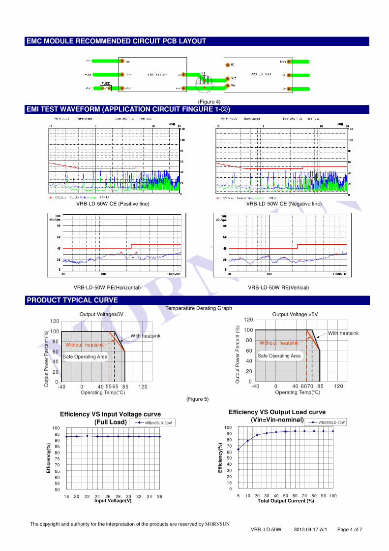
EMC MODULE RECOMMENDED CIRCUIT PCB LAYOUT
(Figure 4)
EMI TEST WAVEFORM (APPLICATION CIRCUIT FINGURE 1- )②
VRB-LD-50W CE (Positive line) VRB-LD-50W CE (Negative line)
VRB-LD-50W RE(Horizontal) VRB-LD-50W RE(Vertical)
PRODUCT TYPICAL CURVE Temperature Derating Graph
Output Voltage≤5V Output Voltage >5V
0
20
40
60
80
100
120
-40 0 40 85 12055 65Operating Temp(°C)
Ou
tpu
t P
ow
er
Pe
rce
nt (%
)
Without heatsink
With heatsink
Safe Operating Area
0
20
40
60
80
100
120
-40 0 40 85 1206070Operating Temp(°C)
Ou
tput
Po
wer
Perc
ent
(%)
Without heatsink
With heatsink
Safe Operating Area
(Figure 5)
Efficiency VS Input Voltage curve
(Full Load)
50
55
60
65
70
75
80
85
90
95
100
18 20 22 24 26 28 30 32 34 36
Input Voltage(V)
Eff
icie
ncy(%
)
VRB2405LD- 50W
Efficiency VS Output Load curve
(Vin=Vin-nominal)
0
10
20
30
40
50
60
70
80
90
100
5 10 20 30 40 50 60 70 80 90 100
Total Output Current (%)
Eff
icie
ncy(%
)
VRB2405LD- 50W

The copyright and authority for the interpretation of the products are reserved by MORNSUN VRB_LD-50W 3013.04.17-A/1 Page 5 of 7
URB_YMD-20W PCB MOUNTING OUTLINE DIMENSIONS,RECOMMENDED FOOTPRINT(WITHOUT HEAT
SINK)
VRB-LD-50WHR2 PCB MOUNTING OUTLINE DIMENSIONS(WITH HEAT SINK)
VRB_LD-50WA2S CHASSIS MOUNTING OUTLINE DIMENSIONS
Footprint Details
Pin 1 2 3 4 5 6
Function Ctrl GND Vin Trim 0V +Vo

The copyright and authority for the interpretation of the products are reserved by MORNSUN VRB_LD-50W 3013.04.17-A/1 Page 6 of 7
VRB_LD-50WA4S DIN-RAIL MOUNTING OUTLINE DIMENSIONS
DIN-rail modules are fitting to TS35 rails
Footprint Details
Pin 1 2 3 4 5 6
Function Ctrl GND Vin Trim 0V +Vo
PACKAGE DIAGRAM
PCB mounting Series(Without heat sink) PCB mounting Series(With heat sink) Special Package Series(A2S/A4S)
TEST CONFIGURATIONS Input Reflected-Ripple Current Test Setup
Input reflected-ripple current is measured with an inductor Lin and Capacitor Cin to simulate source impedance.
DCCin
Lin
DC Load
Oscilloscope
Current Probe
Lin(4.7µH) Cin(220µF, ESR < 1.0Ω at 100 KHz)
TRIM APPLICATION & TRIM RESISTANCE
Application circuit for TRIM (Part in broken line is the interior of models)
0V
R2
R1
R3Vref
RT
Trim
+Vo
0V
R2
R1
R3Vref
RT
Trim
+Vo
Trim up Trim down

The copyright and authority for the interpretation of the products are reserved by MORNSUN VRB_LD-50W 3013.04.17-A/1 Page 7 of 7
Formula for resistance of Trim
up: a=Vref
Vo ’-VrefR1R =T
aR2
R -a2-R3
down: a=Vref
Vo ’-VrefR2R =T
aR1
R -a1-R3
Note: Value for R1, R2, R3, and Vref refer to the above table 1.
RT: Resistance of Trim
a: User-defined parameter, no actual meanings.
Vo’: The trim up/down voltage. (TABLE 1)
Vo Parameter
3.3(VDC) 5(VDC) 12(VDC) 15(VDC) 24(VDC)
R1(KΩ) 4.788 2.87 11 15 20
R2(KΩ) 2.87 2.87 2.87 3 2.308
R3(KΩ) 15 12.1 22 22 15
Vref(V) 1.24 2.5 2.5 2.5 2.5
DESIGN CONSIDERATIONS
①Recommended circuit All the VRB_LD-50W Series have been tested according to the following recommended testing circuit before leaving factory. This series should be
tested under load. Never be tested under no load (see Figure 6). If you want to further decrease the input surge voltage and the output ripple, you can increase a capacitance properly or choose capacitors with
low ESR .It should also be noted that the capacitance of filter capacitor must be proper. If the capacitance is too big, a startup problem might arise. For every channel of output, provided the safe and reliable operation is ensured, the recommended capacitance of its filter capacitor sees (Table 2).
DC DC
Vin
GND
+Vout
0V
Cin
(Figure 6)
EXTERNAL CAPACITOR TABLE (TABLE 2)
Capacitance Output
Voltage Cout(µF) Cin(µF)
3.3V、5V 220
12V、15V 100
24V 47
100
②It is not recommended to increase the output power capability by connecting two or more converters in parallel. The product is not hot-swappable.
Note: 1. Min. load shouldn't be less than 5%, otherwise ripple maybe increased dramatically, If the product operates under min. load, it may not be
guaranteed to meet all specifications listed. Operation under minimum load will not damage the converter. 2. Recommended Dual output models unbalanced load is ≤±5%, If the product operates >±5%, it may not be guaranteed to meet all specifications
listed. Please contact our technical support for more details. 3. Max. Capacitive Load is tested at input voltage range and full load. 4. All specifications measured at Ta=25°C, humidity<75%, nominal input voltage and rated output load unless otherwise specified. 5. In this datasheet, all test methods are based on our corporate standards. 6. All characteristics are for listed models, and non-standard models may perform differently. Please contact our technical support for more details. 7. Please contact our technical support for any specific requirement. 8. Specifications of this product are subject to changes without prior notice.
MORNSUN Science & Technology Co.,Ltd.
Address: No. 5, Kehui St. 1, Kehui development center, Science Ave., Guangzhou Science City, Luogang district, Guangzhou,P.R.China.
Tel: 86-20-38601850
Fax:86-20-38601272
E-mail: [email protected] Http://www.mornsun-power.com