design and analysis of assembly of piston, …...gopal et al design and analysis of assembly of...
TRANSCRIPT
International Journal of Current Engineering and Technology E-ISSN 2277 – 4106, P-ISSN 2347 – 5161 ©2016 INPRESSCO®, All Rights Reserved Available at http://inpressco.com/category/ijcet
Research Article
235| International Journal of Current Engineering and Technology, Vol.6, No.1 (Feb 2016)
Design and analysis of assembly of Piston, Connecting rod and Crank shaft G Gopal†*, L Suresh Kumar‡, D Gopinath‡ and Uma Maheshwara Raoϯ
†Chinthalapudi Engg College, Ponnur, Guntur 522124, India ‡C.B.I.T, Hyderabad, Telangana, India ϯSMICH, Hyderabad, Telangana, India Accepted 05 Feb 2016, Available online 07 Feb 2016, Vol.6, No.1 (Feb 2016)
Abstract The present aim of the project is to study the effect of the materials being used for the Piston, Connecting rod and Crank Shaft assembly for an engine of a four wheeler vehicle. The material selected for the piston is Cast Iron, Manganese steel for the connecting rod and High Carbon Steel for the crank shaft. The engine speed was desired to be increased. The effect of the materials used for the assembly and its behavior was required to be studied. The parts piston, connecting rod and crankshaft are designed using theoretical calculations. The designed parts are modeled and assembled in 3D modeling software Pro/Engineer. The meshing is done in Hypermesh. The Finite Element Analysis is done in Ansys. The FE Analysis involves structural and analysis of the assembly. The parts of the assembly should be rigid. And, when they are connected together, they should perform as a mechanism. This requires calculation of the forces acting on the components and the dynamic stresses. As the assembly will be working under high temperatures, thermal analysis also has to be done. From the results, it is observed that a change in the piston material will allow the engine to operate at the new high speed. Keywords: Engine displacement, Piston skirt, Under square, Crank web, HyperMesh, Ansys. 1. Introduction
1 The assembly of the piston, connecting rod and crank shaft in an engine behaves like a mechanism during the working of the engine. The weight of the Cast Iron piston is preventing the engine to operate at a higher speed. The dimensions of the engine piston, connecting rod and crank shaft are calculated theoretically. Both structural analysis and dynamic analysis are to be done for the assembly. As the piston and the other components of the assembly work under high temperatures, thermal analysis is also done.
The piston, rings, and wrist pin
The piston makes the crankshaft to turn by utilizing the energy supplied to it by the combustion of the fuel. It is cylindrical in shape and reciprocates inside the cylinder. Pistons are provided with groves near the top and provide an air tight fit. The pistons do not allow the high pressure mixture from the combustion chambers into the crankcase. The piston has four strokes in total, two upside and two down. During the intake stroke, the piston moves down and the cylinder is filled with air fuel mixture. The upward stroke *Corresponding author G Gopal, Dr.L Suresh Kumar, D Gopinath and Uma Maheshwara Rao are working as Professors
compresses the mixture and as it reaches near the top position, the ignition of the fuel causes the piston to move downwards, the third stroke. During the fourth stroke, the piston moves upward and pushes the burnt gases to the exhaust system. The piston operates under high pressure and high temperature. The top portion of the piston is called as Crown. It’s bottom is called as skirt. The diameter of the piston crown is less than the skirt. There are groves at the top for oil ring and compression rings. The oil groove is wider and deep than the compression ring. The oil ring scraps the excess oil and returns back and prevents the oil reaching the combustion chamber. Lands are the spaces between the grooves. In the design of pistons, the weight of the piston is an important factor. The top surface of the piston called as “Crown” is provided many shapes viz. convex, concave, and flat to control the combustion. Some pistons are provided with a narrow groove above the top ring to reduce the heat reaching the top ring. The wrist pin connects the connecting rod at the bottom of the piston, wherein the pin connects by passing through the side of the piston.
Piston stroke The piston stroke displacement is determined by the axis of the crank throws from the axis of the crankshaft.
Gopal et al Design and analysis of assembly of Piston, Connecting rod and Crank shaft
236| International Journal of Current Engineering and Technology, Vol.6, No.1 (Feb 2016)
Increasing the stroke increases the low-speed torque of the engine. This increases the reciprocating vibration and limits the high speed capability of the engine. If the stroke is longer than the cylinder bore diameter is called as "Under square" or long-stroke.
Materials for the Piston
Cast Iron, Aluminum Alloy and Cast Steel etc. are the common materials used for piston. These pistons have greater strength and resistance to wear. In Aluminum Alloy pistons piston slap results due to insufficient piston clearance. A vertical slot is cut to overcome the defect. To increase the life of grooves and to reduce the wear, a ferrous metal rings are inserted in the grooves of high speed engines.
Connecting rod
The connecting rod links the piston and the crankshaft. It has a hole at the upper end (small end) and is connected to the piston by the wrist pin. The lower end, also called as Big end, is attached to the crankshaft. The small end is press fit and can swivel in the piston. The Connecting rods are usually made of alloy steel, Titanium and sometimes with aluminum. They are not rigidly fixed at either end, so that the angle between the connecting rod and the piston can change as the rod moves up and down and rotates around the crankshaft. The big end is connected to the bearing journal on the crank throw. The connecting rod is under a lot of stress with every rotation. High factor of safety is provided as the failure of the connecting rod is very likely under such heavy stresses. Attention has to be paid to eliminate the stress risers in the connecting rod during production. Also, the bolts should be tightened with proper torque. Wearing of engine is due to the sideward force exerted on the piston which results into wearing of the cylinder into an oval cross section. For a given engine block, the sum of the length of the connecting rod plus the piston stroke is a fixed number. This is determined by the fixed distance between the crankshaft axis and the top of the cylinder block where the cylinder head fastens. Thus, for a given cylinder block longer stroke, giving greater engine displacement and power, requires a shorter connecting rod (or a piston with smaller compression height), resulting in accelerated cylinder wear.
Materials used for Connecting Rod
Steel has good strength, durability and has less cost. But, it has high density which creates excessive stresses on the crank shaft. This requires a heavier crankshaft for carrying the loads. This causes to limit the maximum RPM of the engine. It also reduces the acceleration or declaration rates of engine speed. Light alloy metals such as aluminum and titanium are used to overcome these problems. Crankshaft The turning motion to the wheels is provided by the crankshaft, which converts the reciprocating motion of
the pistons into a rotary motion. The crankshaft is usually either alloy steel or cast iron. Crankshafts are connected to the pistons by the connecting-rods. The crank shaft has crank throws which are offset from the crank. The big end of the connecting rod is attached to it. The crank shaft is connected to a flywheel to reduce the torsion vibrations. 2. Design calculations Pressure calculations Specifications of the engine
Table 1 Engine specs
Type : air cooled 4-stroke SOHC Bore x stroke (mm) = 79.5 x 80.5 mm Displacement - 1598 Cm3 Maximum power = 77 @5250rpm Maximum torque = 153 @3800 rpm Compression ratio = 9.35/1 Density of petrol = 0.00000073722 kg/mm3 Temperature = 600F
Density of petrol C8H18 = 737.22 kg/m3 at 60 0F = 0.00073722 kg/cm3
= 0.00000073722 kg/mm3 T = 600F =15.550C = 288.855K Mass = density x volume = 0.00000073722 x 159800 = 0.1178kg Molecular cut for petrol 114.2285 g/mole PV = mRT P = (0.1178 x 8.3143 x 288.555) / (0.11422 x 0.0001598) P = 12287695.65 j/m3 = N/m2 Gas pressure, P =12.287 N/mm2 Mean effective pressure, Pm = 2 π (Tnc / Vd) = 153 x 2 x 3.14 / 1598 = 1.202 Indicated power IP = (Pm x l x A x n)/60 = (1.202 x 80.5 x 3.14 x 79.52 x 4)/(4 x 60) = 128018.57 kw Brake power BP = (2 π N T) / 60 = (2 x 3.14 x 5250 x 153) / (4 x 60) = 84073.5 kw Mechanical efficiency, = BP / IP = 84073.5 / 128078.57 = 0.656 = 65.6%
Piston
Material: Cast Iron
Temperature at the center of piston head
Tc = 2600c to 2900c
Temperature at the edge of piston head
Gopal et al Design and analysis of assembly of Piston, Connecting rod and Crank shaft
237| International Journal of Current Engineering and Technology, Vol.6, No.1 (Feb 2016)
Te = 1850c to 2150c
Maximum gas pressure p = 12.287/mm2
Bore or outside diameter of piston = 79.5mm
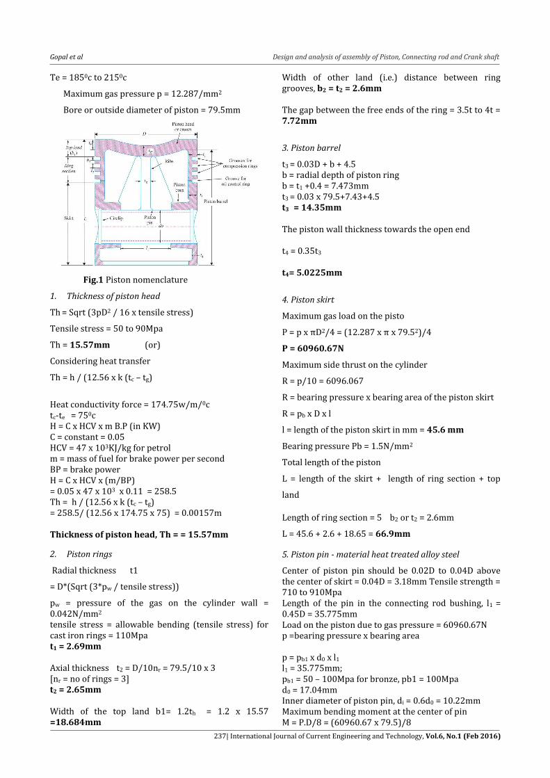
Fig.1 Piston nomenclature
1. Thickness of piston head
Th = Sqrt (3pD2 / 16 x tensile stress)
Tensile stress = 50 to 90Mpa
Th = 15.57mm (or)
Considering heat transfer
Th = h / (12.56 x k (tc – tg)
Heat conductivity force = 174.75w/m/0c tc-te = 750c H = C x HCV x m B.P (in KW) C = constant = 0.05 HCV = 47 x 103KJ/kg for petrol m = mass of fuel for brake power per second BP = brake power H = C x HCV x (m/BP) = 0.05 x 47 x 103 x 0.11 = 258.5 Th = h / (12.56 x k (tc – tg) = 258.5/ (12.56 x 174.75 x 75) = 0.00157m Thickness of piston head, Th = = 15.57mm
2. Piston rings
Radial thickness t1
= D*(Sqrt (3*pw / tensile stress))
pw = pressure of the gas on the cylinder wall = 0.042N/mm2 tensile stress = allowable bending (tensile stress) for cast iron rings = 110Mpa t1 = 2.69mm Axial thickness t2 = D/10nr = 79.5/10 x 3 [nr = no of rings = 3] t2 = 2.65mm
Width of the top land b1= 1.2th = 1.2 x 15.57 =18.684mm
Width of other land (i.e.) distance between ring grooves, b2 = t2 = 2.6mm
The gap between the free ends of the ring = 3.5t to 4t = 7.72mm
3. Piston barrel
t3 = 0.03D + b + 4.5 b = radial depth of piston ring b = t1 +0.4 = 7.473mm t3 = 0.03 x 79.5+7.43+4.5 t3 = 14.35mm The piston wall thickness towards the open end t4 = 0.35t3 t4= 5.0225mm
4. Piston skirt
Maximum gas load on the pisto
P = p x πD2/4 = (12.287 x π x 79.52)/4
P = 60960.67N
Maximum side thrust on the cylinder
R = p/10 = 6096.067
R = bearing pressure x bearing area of the piston skirt
R = pb x D x l
l = length of the piston skirt in mm = 45.6 mm
Bearing pressure Pb = 1.5N/mm2
Total length of the piston
L = length of the skirt + length of ring section + top
land
Length of ring section = 5 b2 or t2 = 2.6mm
L = 45.6 + 2.6 + 18.65 = 66.9mm
5. Piston pin - material heat treated alloy steel
Center of piston pin should be 0.02D to 0.04D above the center of skirt = 0.04D = 3.18mm Tensile strength = 710 to 910Mpa Length of the pin in the connecting rod bushing, l1 = 0.45D = 35.775mm Load on the piston due to gas pressure = 60960.67N p =bearing pressure x bearing area
p = pb1 x d0 x l1 l1 = 35.775mm; pb1 = 50 – 100Mpa for bronze, pb1 = 100Mpa d0 = 17.04mm Inner diameter of piston pin, di = 0.6d0 = 10.22mm Maximum bending moment at the center of pin M = P.D/8 = (60960.67 x 79.5)/8
Gopal et al Design and analysis of assembly of Piston, Connecting rod and Crank shaft
238| International Journal of Current Engineering and Technology, Vol.6, No.1 (Feb 2016)
M = 605796.658s N-mm Z = π/32 [{(d0)4 – (dc)4 }/d0] = 4445.0689 Allowable bending stress σb = M/Z = 139.02 This is less than the allowable value 140mpa for heat treated alloy steel The mean diameter of the piston bosses = 1.5d0 = 1.5 x 17.04 = 25.56mm Design calculations of connecting rod 1. Dimensions of cross section of connecting rod
Thickness of flange & web of the section = t
Width of section B= 4t
Height of section H=5t Area of section A= 2(4t×t) +3t×t A=11t² MI of section about x axis, Ixx=1\12 (4t (5t) 3-3t (3t) 3) =419\12t4 MI of section about y axis, IYY= (2+1\12t (4t) 3+1\12 (3t) t3) = 131\12 t4 IXX\ IYY= 3.2 Length of connecting rod = 2 times the stroke L= 2×80.5 =161mm Buckling load wB = maximum gas force × F.O.S WB =60960.67× 6 =365764.02 WB = σC×A 1+ a(L\KXX)2 σC = compressive yield stress= 172 MPa
kxx= IXX\A= 419\12t4
11t2
= 3.17t2 = 1.78t
fc= maximum load fc= p= 39414.88611 a= fc \π2E a= 39414.88611 π² × 80000
a = 0.05 236489.3166 = 172 ×11t² 1+0.05(161/1.78t)2 5993.856t4-749198.1551t2-162418497.747714=0 On solving, t = 23.32mm Width of section, B = 4t =93.28mm
Height of section, H = 5t = 116.6mm
Area A = 11t2 = 5982.64mm2
Height at the big end (crank end) = H2 = 1.1H to 1.25H
H2 =128.26 mm
Height at the small end (piston end) = 0.9H
H1 =104.94mm
2. Dimensions of crank pin
Load on the crank pin = projected area × bearing
pressure, FL =dc × lc ×pbc
lc = 1.25 dc to 1.5dc
FL = 1.5 dc2× pbc
pbc= allowable bearing press. at the crank pin bearing pbc= 12.5N/mm2 FL = (πD2 / 4) x P = 60960.67 60960.67 = 1.5 dc
2× 12.5
dc2 = 3251.2357 = 57.01mm
lc = 1.5dc = 85.515mm
3. Piston pin (gudgeon pin (or) wrist pin)
do=outside dia of the piston pin
l1=length of the piston pin in the bush of the small end
of the connecting rod in mm
l1=0.45D=0.45×79.5=35.775mm Load on the piston due to gas pressure Pmax= (πD2 / 4) x P = 62017.45 N Load on the piston pin due to bearing pressure (or) Bearing load=bearing pressure bearing area Load = Pb1×do×l1 Pb1=bearing pressure at the small end of the connecting rod bushing Pb1=77.28N/mm2 60960.67=77.28× do×35.77 do = 22.05mm di=0.6 do=13.23mm length between the supports l2 = (l1 + D)/2 = 57.635mm Crankshaft D = piston diameter or cylinder bore = 79.5 mm P = maximum intensity of pressure on the piston = 12.287 N/mm2 Fp = thrust in the connecting rod will be equal to the gas load on the piston = ∏/4×D2×p dc = Diameter of crankpin = 57.01 mm [taken from the big end of connecting rod] lc = length of crankpin = 85.515 mm Due to the piston gas load (Fp) acting horizontally, there will be two horizontal reactions H1 & H2 at bearings 1 & 2 respectively. Considering the crankpin as simply supported beam i.e., H1 = H2 = H1 + H2 = Fp = 30462.97 N b = distance between the bearings 1 & 2 is equal to twice the piston diameter = 2D = 2×79.5 = 159 mm b1 = b2 = b/2 = 79.5 mm
1. Design of left hand crank web
Thickness of the crank web t = 0.4ds to 0.6ds = 0.22D to 0.32D = 0.65ds + 6.35 =0.32×79.5 = 25.44 mm [from 0.32D]
Gopal et al Design and analysis of assembly of Piston, Connecting rod and Crank shaft
239| International Journal of Current Engineering and Technology, Vol.6, No.1 (Feb 2016)
Width of the crank web w = 1.125dc + 12.5 = 1.125×57.01+12.5 = 76.63 mm Maximum bending moment on the crank web M = H1 (b2 – lc/2 – t/2) = 30462.97 (79.5– 85.5/2 – 2445./2) = 732025.1691 N-mm Section modulus Z = 1/6 wt2 = 1/6×76.63×25.442 = 8265.74 mm3 Bending stress on crank web Σb = M/Z = 732025.1691/8265.74 = 88.56 N/mm2 Compressive stress on the crank web Σc = H1 /wt = 30462.97/(6376.×25.44) = 15.62N/mm2 Total stress of crank web Σ = Σb + Σc = 88.56+15.62 = 104.18N/mm2 Here total stress is less than the yield strength of carbon steel (560N/mm2) ds = diameter of the shaft in mm t = 0.4ds to 0.6ds ds = t/0.6 = 25.44/0.6 = 42.4mm 3. Analysis procedure
a. 2D drawings
Fig.2 Piston drawing
Fig.3 Connecting rod
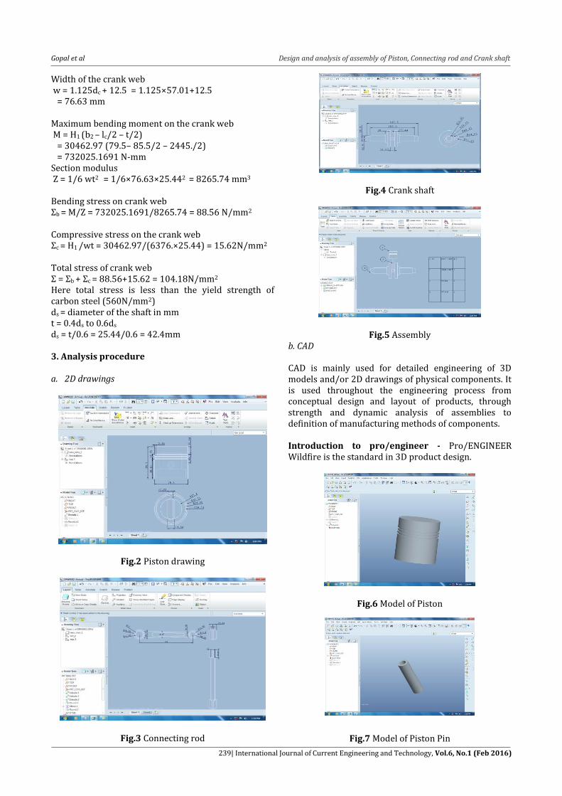
Fig.4 Crank shaft
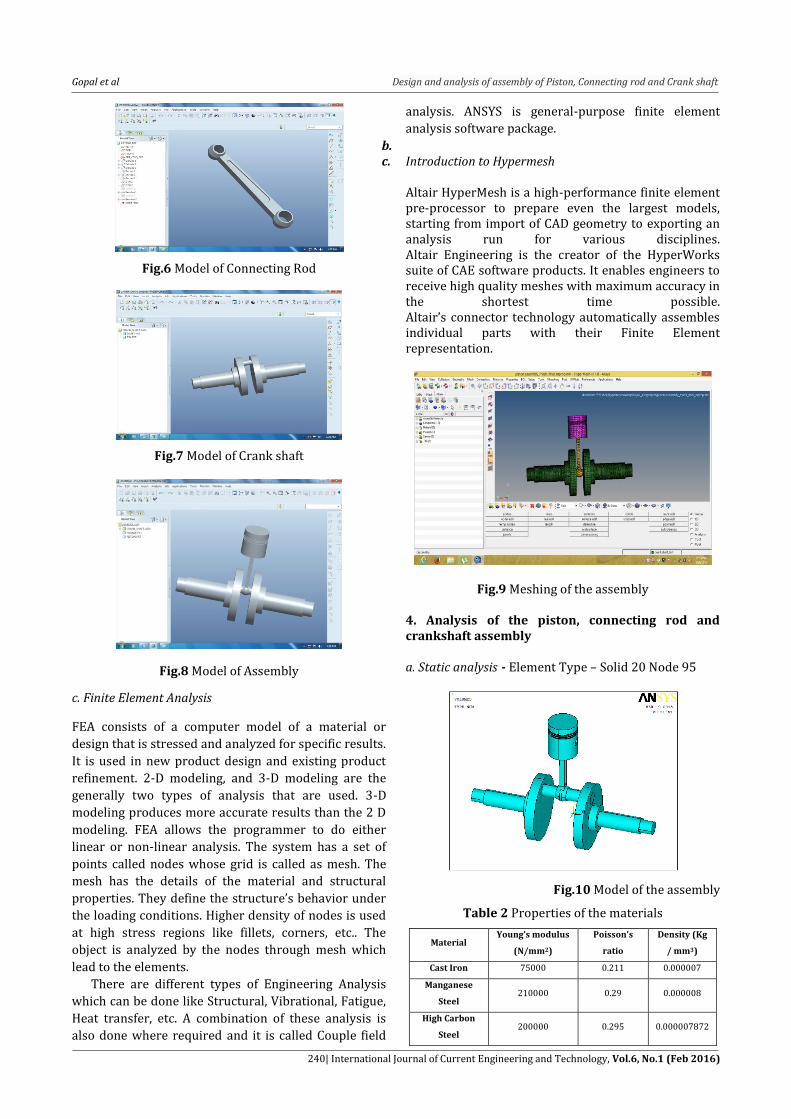
Fig.5 Assembly b. CAD CAD is mainly used for detailed engineering of 3D models and/or 2D drawings of physical components. It is used throughout the engineering process from conceptual design and layout of products, through strength and dynamic analysis of assemblies to definition of manufacturing methods of components. Introduction to pro/engineer - Pro/ENGINEER Wildfire is the standard in 3D product design.
Fig.6 Model of Piston
Fig.7 Model of Piston Pin
Gopal et al Design and analysis of assembly of Piston, Connecting rod and Crank shaft
240| International Journal of Current Engineering and Technology, Vol.6, No.1 (Feb 2016)
Fig.6 Model of Connecting Rod
Fig.7 Model of Crank shaft
Fig.8 Model of Assembly
c. Finite Element Analysis
FEA consists of a computer model of a material or
design that is stressed and analyzed for specific results.
It is used in new product design and existing product
refinement. 2-D modeling, and 3-D modeling are the
generally two types of analysis that are used. 3-D
modeling produces more accurate results than the 2 D
modeling. FEA allows the programmer to do either
linear or non-linear analysis. The system has a set of
points called nodes whose grid is called as mesh. The
mesh has the details of the material and structural
properties. They define the structure’s behavior under
the loading conditions. Higher density of nodes is used
at high stress regions like fillets, corners, etc.. The
object is analyzed by the nodes through mesh which
lead to the elements.
There are different types of Engineering Analysis
which can be done like Structural, Vibrational, Fatigue,
Heat transfer, etc. A combination of these analysis is
also done where required and it is called Couple field
analysis. ANSYS is general-purpose finite element
analysis software package.
b. c. Introduction to Hypermesh
Altair HyperMesh is a high-performance finite element pre-processor to prepare even the largest models, starting from import of CAD geometry to exporting an analysis run for various disciplines. Altair Engineering is the creator of the HyperWorks suite of CAE software products. It enables engineers to receive high quality meshes with maximum accuracy in the shortest time possible. Altair’s connector technology automatically assembles individual parts with their Finite Element representation.
Fig.9 Meshing of the assembly 4. Analysis of the piston, connecting rod and crankshaft assembly a. Static analysis - Element Type – Solid 20 Node 95
Fig.10 Model of the assembly
Table 2 Properties of the materials
Material Young’s modulus
(N/mm2)
Poisson’s
ratio
Density (Kg
/ mm3)
Cast Iron 75000 0.211 0.000007
Manganese
Steel 210000 0.29 0.000008
High Carbon
Steel 200000 0.295 0.000007872

Gopal et al Design and analysis of assembly of Piston, Connecting rod and Crank shaft
241| International Journal of Current Engineering and Technology, Vol.6, No.1 (Feb 2016)
Fig.11 Meshed model
Fig.12 Displacement with Loads – Pressure on Areas –
12.26N/mm2
Fig.13 Von Mises Stress
b. Thermal analysis –Element Type – Solid 20Node 90
Table 3 Material’s thermal properties
Material Density
(Kg / mm3)
Thermal
conductivity
(W/m k)
Specific
heat
( J/ g C)
Cast Iron 0.000007 53.0 0.506
Manganese
Steel 0.000008 51.9 0.472
High Carbon
Steel 0.00000787 52.0 0.669
Loads : Temperature on Areas – 973K
Convection: Film Coefficient – 0.000025W/m2K
Bulk Temperature – 570K
Fig.14 Nodal temperatures
Fig.15 Thermal gradient
Fig.16 Thermal flux
c. Dynamic analysis-Element Type – Solid 20Node 95 Loads
Time Step – 10secs, Pressure – 12.26N/mm2
Time Step – 20secs, Pressure – 18.39N/mm2
Time Step – 30secs, Pressure – 30.65N/mm2
Fig.17 Loads at different time and Pressures
Gopal et al Design and analysis of assembly of Piston, Connecting rod and Crank shaft
242| International Journal of Current Engineering and Technology, Vol.6, No.1 (Feb 2016)
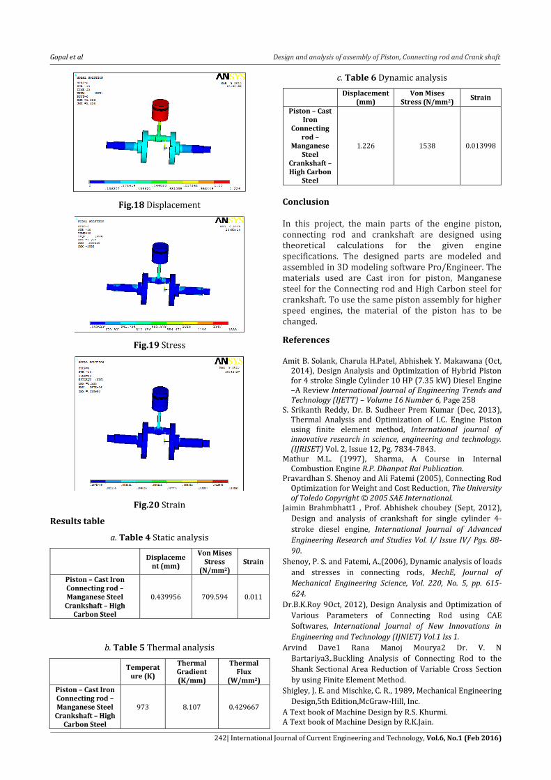
Fig.18 Displacement
Fig.19 Stress
Fig.20 Strain
Results table
a. Table 4 Static analysis
Displaceme
nt (mm)
Von Mises Stress
(N/mm2) Strain
Piston – Cast Iron Connecting rod – Manganese Steel
Crankshaft – High Carbon Steel
0.439956 709.594 0.011
b. Table 5 Thermal analysis
Temperat
ure (K)
Thermal Gradient (K/mm)
Thermal Flux
(W/mm2) Piston – Cast Iron Connecting rod – Manganese Steel
Crankshaft – High Carbon Steel
973 8.107 0.429667
c. Table 6 Dynamic analysis
Displacement
(mm) Von Mises
Stress (N/mm2) Strain
Piston – Cast Iron
Connecting rod –
Manganese Steel
Crankshaft – High Carbon
Steel
1.226 1538 0.013998
Conclusion In this project, the main parts of the engine piston, connecting rod and crankshaft are designed using theoretical calculations for the given engine specifications. The designed parts are modeled and assembled in 3D modeling software Pro/Engineer. The materials used are Cast iron for piston, Manganese steel for the Connecting rod and High Carbon steel for crankshaft. To use the same piston assembly for higher speed engines, the material of the piston has to be changed.
References Amit B. Solank, Charula H.Patel, Abhishek Y. Makawana (Oct,
2014), Design Analysis and Optimization of Hybrid Piston for 4 stroke Single Cylinder 10 HP (7.35 kW) Diesel Engine –A Review International Journal of Engineering Trends and Technology (IJETT) – Volume 16 Number 6, Page 258
S. Srikanth Reddy, Dr. B. Sudheer Prem Kumar (Dec, 2013), Thermal Analysis and Optimization of I.C. Engine Piston using finite element method, International journal of innovative research in science, engineering and technology. (IJRISET) Vol. 2, Issue 12, Pg. 7834-7843.
Mathur M.L. (1997), Sharma, A Course in Internal Combustion Engine R.P. Dhanpat Rai Publication.
Pravardhan S. Shenoy and Ali Fatemi (2005), Connecting Rod Optimization for Weight and Cost Reduction, The University of Toledo Copyright © 2005 SAE International.
Jaimin Brahmbhatt1 , Prof. Abhishek choubey (Sept, 2012),
Design and analysis of crankshaft for single cylinder 4-
stroke diesel engine, International Journal of Advanced
Engineering Research and Studies Vol. I/ Issue IV/ Pgs. 88-
90.
Shenoy, P. S. and Fatemi, A.,(2006), Dynamic analysis of loads
and stresses in connecting rods, MechE, Journal of
Mechanical Engineering Science, Vol. 220, No. 5, pp. 615-
624.
Dr.B.K.Roy 9Oct, 2012), Design Analysis and Optimization of
Various Parameters of Connecting Rod using CAE
Softwares, International Journal of New Innovations in
Engineering and Technology (IJNIET) Vol.1 Iss 1.
Arvind Dave1 Rana Manoj Mourya2 Dr. V. N
Bartariya3,.Buckling Analysis of Connecting Rod to the
Shank Sectional Area Reduction of Variable Cross Section
by using Finite Element Method.
Shigley, J. E. and Mischke, C. R., 1989, Mechanical Engineering
Design,5th Edition,McGraw-Hill, Inc.
A Text book of Machine Design by R.S. Khurmi. A Text book of Machine Design by R.K.Jain.