iv piston ring assembly of a new symmetrical multi
TRANSCRIPT

iv
PISTON RING ASSEMBLY OF A NEW SYMMETRICAL
MULTI-STAGE WOBBLE-PLATE COMPRESSOR
ANDRIL ARAFAT SUHASRIL
A thesis submitted in fulfillment of the
requirements for the award of degree of
Master of Engineering
Faculty of Mechanical Engineering
Universiti Teknologi Malaysia
MAY 2008

vi
To my beloved wife, son and all my big family

vii
ACKNOWLEDGEMENTS
All praises to The Almighty Allah SWT for making everything possible. In
preparing this thesis, I was in contact with many people, researchers, academicians,
and practitioners. They have contributed towards my understanding and thoughts. In
particular, I wish to express my sincere appreciation to my supervisors, Prof. Dr. Md
Nor Musa and Prof. Dr. Ir. Wan Ali Wan Mat, for encouragement, guidance,
contribution and friendship. Without their continued support and interest, this thesis
would not have been the same as presented here.
I am also very thankful to En. Ainullotfi Abdul Latif and all the Researchers
and Research Officers in the UTM Compressor Research Group for their guidance,
advices and motivation. I am also indebted to Universiti Teknologi Malaysia (UTM),
to CNG/DI Engine and Transmission Program, to Ministry of Science Technology
and Innovation (MOSTI) for support and funding my study as a whole.
I would like to thank Dr. Ir. Henry Nasution, MT, Ardiyansyah Syahrom, ST.
MEng, Zair Asrar Ahmad, MEng, Ir. Saiful Jamaan, MEng, Ir. Oktaviandri, MT for
all encouragement and support. As same appreciation is extended to all my
colleagues and others who have provided assistance at various occasions.
Unfortunately, it is not possible to list all of them in this limited space.
I am very grateful to my family, especially thank my wife Era Triana, ST,
MSc and my son Muhammad Alfatih Arafat, for love, prayer, patience and
assistance. As same appreciation is extended to my parents and in-laws, brothers,
sister and to all my big family members for all of their love and support.
viii
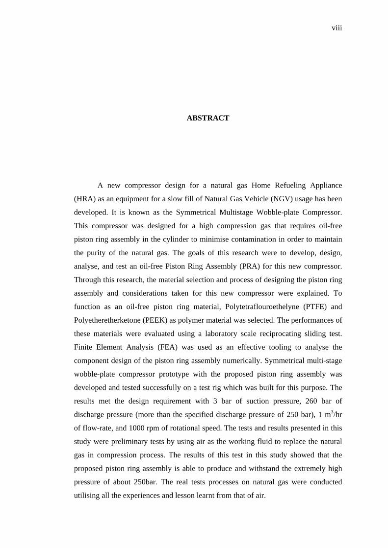
ABSTRACT
A new compressor design for a natural gas Home Refueling Appliance
(HRA) as an equipment for a slow fill of Natural Gas Vehicle (NGV) usage has been
developed. It is known as the Symmetrical Multistage Wobble-plate Compressor.
This compressor was designed for a high compression gas that requires oil-free
piston ring assembly in the cylinder to minimise contamination in order to maintain
the purity of the natural gas. The goals of this research were to develop, design,
analyse, and test an oil-free Piston Ring Assembly (PRA) for this new compressor.
Through this research, the material selection and process of designing the piston ring
assembly and considerations taken for this new compressor were explained. To
function as an oil-free piston ring material, Polytetraflouroethelyne (PTFE) and
Polyetheretherketone (PEEK) as polymer material was selected. The performances of
these materials were evaluated using a laboratory scale reciprocating sliding test.
Finite Element Analysis (FEA) was used as an effective tooling to analyse the
component design of the piston ring assembly numerically. Symmetrical multi-stage
wobble-plate compressor prototype with the proposed piston ring assembly was
developed and tested successfully on a test rig which was built for this purpose. The
results met the design requirement with 3 bar of suction pressure, 260 bar of
discharge pressure (more than the specified discharge pressure of 250 bar), 1 m3/hr
of flow-rate, and 1000 rpm of rotational speed. The tests and results presented in this
study were preliminary tests by using air as the working fluid to replace the natural
gas in compression process. The results of this test in this study showed that the
proposed piston ring assembly is able to produce and withstand the extremely high
pressure of about 250bar. The real tests processes on natural gas were conducted
utilising all the experiences and lesson learnt from that of air.

ix
ABSTRAK
Satu rekabentuk pemampat baru untuk Aplikasi Pengisian Semula Kediaman
(HRA) yang merupakan sebahagian daripada peralatan pengisian semula kenderaan
gas asli (NGV) telah dibangunkan. Rekabentuk baru ini dikenali sebagai pemampat
plat wobal simetri berbilang peringkat. Pemampat ini direkabentuk untuk
pemampatan gas asli bertekanan tinggi yang memerlukan penggunaan gegelang
piston bebas minyak di dalam cylinder pemampatan untuk mengurangkan
pencemaran dan mengekalkan ketulenan gas asli tersebut. Objektif kajian ini adalah
pembangunan, rekabentuk, analisa serta ujikaji terhadap gegelang piston untuk
kegunaan rekabentuk pepampat baru tersebut. Di dalam kajian ini juga, proses
pemilihan bahan, merekabentuk gegelang piston dan pertimbangan yang diambil
untuk pemampat baru ini diterangkan. Dua bahan polimer yang berfungsi untuk
gegelang piston bebas minyak telah dipilih iaitu Polytetraflouroethelyne (PTFE) dan
Polyetheretherketone (PEEK). Prestasi bahan-bahan ini ditentukan dengan
menggunakan ujian gelinciran ulang-alik berskala makmal. Analisis Kaedah Unsur
Terhingga (FEM) telah digunakan untuk menganalisa rekabentuk gegelang piston
secara analitikal. Pemampat yang dilengkapi dengan rekabentuk gegelang piston
bebas minyak yang dicadangkan ini telah dibangunkan dan diuji dengan pelantar
ujian yang telah dibina. Hasil ujikaji memenuhi keperluan rekabentuk iaitu tekanan
masukan sebanyak 3 bar, tekanan keluaran sebanyak 260 bar (melebihi keperluan
rekabentuk iaitu 250 bar), kadar alir sebanyak 1 m3/hr dan halaju operasi sebanyak
1000rpm. Ujikaji dan keputusan yang diberikan di dalam kajian ini adalah
merupakan kajian awalan di mana udara digunakan bagi menggantikan gas asli di
dalam proses pemampatan. Keputusan ujikaji di dalam kajian ini menunjukkan
bahawa gegelang piston yang dibangunkan ini mampu untuk menahan tekanan tinggi
sehingga 250bar. Proses pengujian sebenar menggunakan gas asli akan dapat
dipandu daripada pengalaman dan contoh pengujian menggunakan udara ini.
x
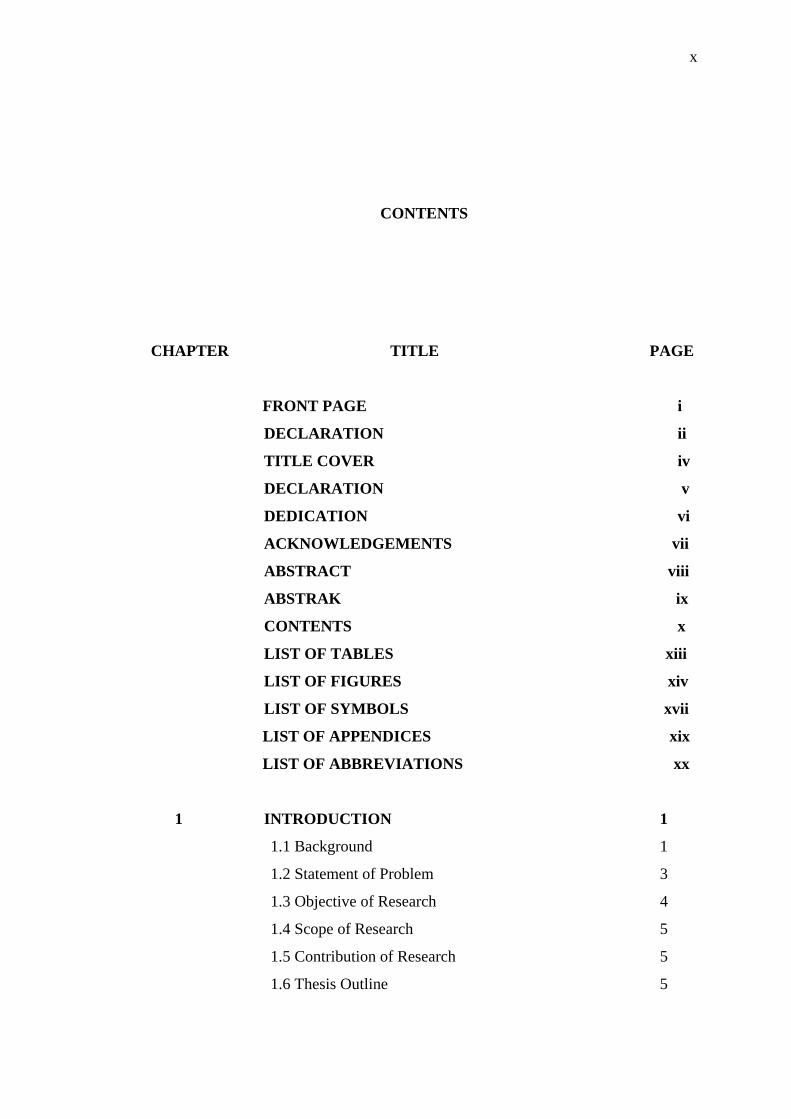
CONTENTS
CHAPTER TITLE PAGE
FRONT PAGE i
DECLARATION ii
TITLE COVER iv
DECLARATION v
DEDICATION vi
ACKNOWLEDGEMENTS vii
ABSTRACT viii
ABSTRAK ix
CONTENTS x
LIST OF TABLES xiii
LIST OF FIGURES xiv
LIST OF SYMBOLS xvii
LIST OF APPENDICES xix
LIST OF ABBREVIATIONS xx
1 INTRODUCTION 1
1.1 Background 1
1.2 Statement of Problem 3
1.3 Objective of Research 4
1.4 Scope of Research 5
1.5 Contribution of Research 5
1.6 Thesis Outline 5

xi
2 LITERATURE REVIEW 8
2.1 Introduction 8
2.2 Oil Lubricated and Non Lubricated Cylinder 9
2.3 History and Development of Oil-Free Reciprocating
Compressor 13
2.4 Material development for Oil –Free Piston Ring 17
2.5 Piston Rings Design 24
2.6 Wear of Piston Ring 26
2.7 Computer Modeling and Stimulation 28
2.8 Design Study of an Existing Computer Model 29
3 THEORY OF PISTON RING ASSEMBLY 33
3.1 Material 33
3.1.1 Techniques of Material Selection 33
3.1.2 Piston Ring Design and Material 35
3.1.3 Piston Design and Material 36
3.1.4 Cylinder Liner Design and Material 38
3.2 Design and Analysis 38
3.2.1 Loads and Forces Acting On Piston Ring 39
3.2.2 Elastic of Piston Ring 41
3.2.3 Piston Ring Forces 46
3.2.3.1 Inertial Force 47
3.2.3.2 Pressure Force 47
3.2.3.3 Friction Force 48
3.3 Ring Flutter 48
3.4 Ring Collapse 49
3.5 Gas Leakage on Piston Rings 52
3.6 Wear of Piston Ring – Cylinder Liner 55
3.6.1 Surface Texture of Piston Ring 57
3.6.2 Wear Mechanism 60
3.7 Symmetrical Multistage Wobble-plate Compressor 63
3.8 Installation of Piston Ring 66
xii
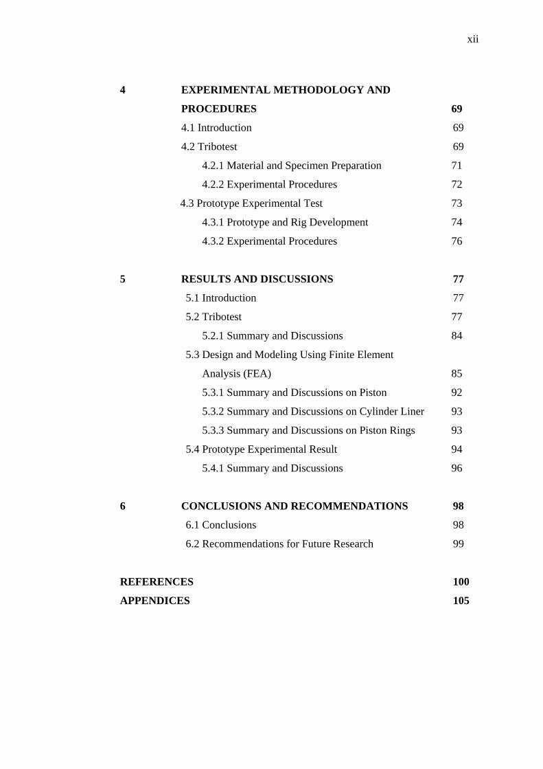
4 EXPERIMENTAL METHODOLOGY AND
PROCEDURES 69
4.1 Introduction 69
4.2 Tribotest 69
4.2.1 Material and Specimen Preparation 71
4.2.2 Experimental Procedures 72
4.3 Prototype Experimental Test 73
4.3.1 Prototype and Rig Development 74
4.3.2 Experimental Procedures 76
5 RESULTS AND DISCUSSIONS 77
5.1 Introduction 77
5.2 Tribotest 77
5.2.1 Summary and Discussions 84
5.3 Design and Modeling Using Finite Element
Analysis (FEA) 85
5.3.1 Summary and Discussions on Piston 92
5.3.2 Summary and Discussions on Cylinder Liner 93
5.3.3 Summary and Discussions on Piston Rings 93
5.4 Prototype Experimental Result 94
5.4.1 Summary and Discussions 96
6 CONCLUSIONS AND RECOMMENDATIONS 98
6.1 Conclusions 98
6.2 Recommendations for Future Research 99
REFERENCES 100
APPENDICES 105
xiii
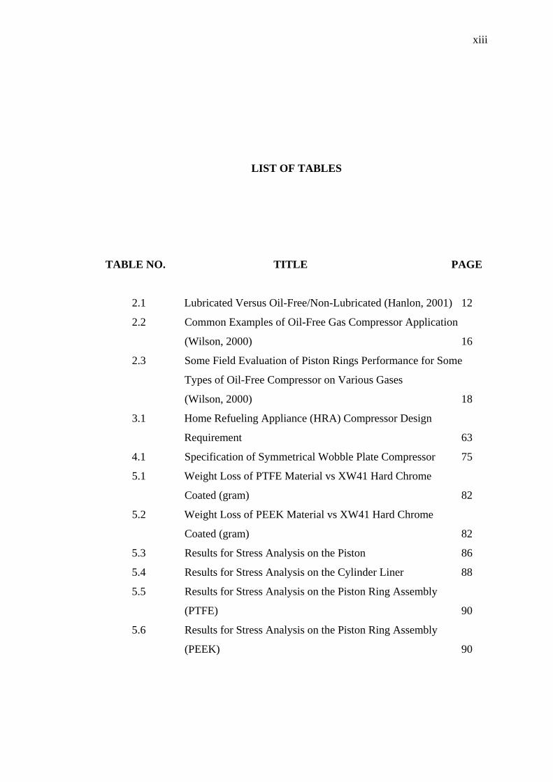
LIST OF TABLES
TABLE NO. TITLE PAGE
2.1 Lubricated Versus Oil-Free/Non-Lubricated (Hanlon, 2001) 12
2.2 Common Examples of Oil-Free Gas Compressor Application
(Wilson, 2000) 16
2.3 Some Field Evaluation of Piston Rings Performance for Some
Types of Oil-Free Compressor on Various Gases
(Wilson, 2000) 18
3.1 Home Refueling Appliance (HRA) Compressor Design
Requirement 63
4.1 Specification of Symmetrical Wobble Plate Compressor 75
5.1 Weight Loss of PTFE Material vs XW41 Hard Chrome
Coated (gram) 82
5.2 Weight Loss of PEEK Material vs XW41 Hard Chrome
Coated (gram) 82
5.3 Results for Stress Analysis on the Piston 86
5.4 Results for Stress Analysis on the Cylinder Liner 88
5.5 Results for Stress Analysis on the Piston Ring Assembly
(PTFE) 90
5.6 Results for Stress Analysis on the Piston Ring Assembly
(PEEK) 90
xiv
LIST OF FIGURES
FIGURE NO. TITLE PAGE
1.1 Flowchart of Research Phases 7
2.1 Typical Piston Rings Ring Assembly of Lubricated Cylinder
Construction (Bloch and Hoefner, 1996) 11
2.2 Typical of Oil-Free Piston and Ride Rings
(Bloch and Hoefner, 1996) 13
2.3 Early Version of Oil-Free Compressor Piston
(Bloch and Hoefner, 1996) 14
2.4 Transfer Film Mechanisms (Dwivedi, 1990) 23
2.5 Scanning Electron Microscopic (SEM) of PTEE Transfer
Film (Dwivedi, 1990) 24
2.6 Typical of Scotch Yoke Compressor 29
2.7 Plunger Piston of Scotch-Yoke Compressor 30
3.1 Flowchart of Material Selection 33
3.2 Scotch-Yoke Compressor and PTFE Added Filter as Piston
Ring 35
3.3 Typical Piston Design (Bloch and Hoefner, 1996) 37
3.4 Cross-Section View of Two Pieces Piston Ring Assembly
in its Sealing Position (SAE, 1969) 40
3.5 Gas Pressure on Two Pieces Piston Ring (SAE, 1969) 41
3.6 Free Body Diagram of a Ring Considering Elastic Ring
Tension Only 42
3.7 Plane Elastic Ring with Uniform Pressure 44
3.8 Piston Ring with Uniform Elastic Ring Pressure 45
xv
3.9 Force Balance Condition for Ring Collapse 50
FIGURE NO. TITLE PAGE
3.10 Three Possible Paths of Gas Leakage Through the Rings 53
3.11 Various Types of Cut Joints for Piston Rings 55
3.12 Rubbing of Two Contact Surface Under Microscopic View
(Chui, 2001) 56
3.13 Surface Profile (Chui, 2001) 57
3.14 Two Different Surface Profiles (Chui, 2001) 58
3.15 Surface Representation Using Abbott Firestone Curve (AFC)
(Chui, 2001) 59
3.16 Small Section of Piston Ring Sliding on Cylinder Liner 61
3.17 Ring Section Contact with Cylinder Liner 61
3.18 Piston Rings in Slices Partition 62
3.19 Cross Section of the Symmetrical Multi-Stage Wobble-Plate
Compressor 65
3.10 Cross-Section of Piston Assembly (First Stage Piston) 66
3.21 Installation processes of the un-cut piston ring
into the piston groove 68
4.1 DUCOM Reciprocatory Friction and Wear Test
Monitoring Machine 71
4.2 Surface Roughness Test For Cylinder Liner
(Material XW41 Hard Chrome Coated) 72
4.3 First prototype of symmetrical wobble-plate compressor
Home Refuelling Appliance (HRA) 74
4.4 Experimental Rig of HRA 76
5.1 Transfer Film Phenomenons 78
5.2 Coefficient of Friction of PTFE Vs XW41 Hard Chrome
Coated 79
5.3 Coefficient of Friction of PEEK Vs XW41 Hard Chrome
Coated 79
5.4 Wear of PTFE Vs XW41 Hard Chrome Coated 80
5.5 Wear of PEEK Vs XW41 Hard Chrome Coated 80
xvi
5.6 Temperature of PEEK vs XW41 Hard Chrome Coated 81
5.7 Humidity of PEEK vs XW41 Hard Chrome Coated 81
5.8 Weight loss of pin (PTFE) 82
5.9 Weight loss of plate (PTFE) 83
5.10 Weight loss of pin (PEEK) 83
5.11 Weight loss of plate (PEEK) 84
5.12 Loads and Boundary conditions of the Piston (First Stage) 86
5.13 Von Mises Stress of the Piston (First Stage) 86
5.14 Deformation of the Piston (First Stage) 87
5.15 Factor of Safety of the Piston (First Stage) 87
5.16 Loads and Boundary Conditions of the Cylinder Liner
(First Stage) 88
5.17 Von Mises Stress of the Piston (First Stage) 88
5.18 Deformation of the Cylinder Liner (First Stage) 89
5.19 Factor of Safety of the Cylinder Liner (First Stage) 89
5.20 Loads and Boundary Conditions of the Piston Ring (PTFE) 90
5.21 Von Mises Stress of the Piston Ring (PTFE) 91
5.22 Deformation of the Piston Ring (PTFE) 91
5.23 Factor of Safety of the Piston Ring (PTFE) 92
5.24 Graph of Pressure vs Time, First Test 94
5.25 Graph of Pressure vs Time, Second Test 95
5.26 Graph of Pressure vs Time, Third Test 95
5.27 Graph of Pressure vs Time, Fourth Test 96

xvii
LIST OF SYMBOLS
A - Piston ring surface area
Ar - Area of cross-section of the piston ring
a - The axial acceleration of the piston ring
am - Moment arm on the piston ring
D - Bore diameter
d - Bore diameter minus two times of the ring width
Em - Modulus elasticity
Fl - Inertial force
Ff - Friction force
I - Area moment of inertia of connecting rod
Iz - Area moment of inertia of piston ring
G - Modulus of elasticity in shear
Mz - Bending moment on the piston ring
m - Mass of the ring
N - Normal force on piston ring
n - Free gap ring
P - Pressure
Pe - Elastic ring pressure at outer radius
Pm - Elastic ring pressure at mean radius
p - Force, which put the ring into loaded shape
q - Loaded ring gap
rm - Piston ring mean radius
rm - Piston ring outer radius

xviii
t - Piston ring thickness in axial direction
Ub - Piston ring strain energy due to bending
Un - Piston ring strain energy due to normal force
Us - Piston ring strain energy due to shear force
V - Shear force on piston ring
x, y - Rectangular coordinates
γ - Piston ring end gap angle
υ - Poisson ratio
δb - Deflection of piston ring due to bending force
δn - Deflection of piston ring due to normal force
δs - Deflection of piston ring due to shear force
δt - Total deflection of the piston ring
µ - Kinematics coefficient of friction
υax - Piston ring in axial velocity
xix
LIST OF APPENDICES
APPENDIX TITLE PAGE
Appendix A Piston Groove Dimension of Piston Ring
(According to ISO 7425/1) 105
Appendix B Piston Groove Dimension of Rider/ Guide Ring
(According to ISO 7425/1) 107
Appendix C Material properties of Piston Ring Assembly (PRA) 109
Appendix D Patent Filing No: 2005 5056
Wobble plate Compressor 113
xx
LIST OF ABBREVIATIONS
CNG - Compressed Natural Gas
NGV - Natural Gas Vehicle
HRA - Home Refueling Appliance
PRA - Piston Ring Assembly
TDC - Top Dead Centre
VRA - Vehicle Refueling Appliance

CHAPTER I
INTRODUCTION
1.1 Background
In response to high petroleum price and environmental concerns, natural gas
becomes an alternative fuel in the market today, as well as solving out of
environmental issues on the higher emission of gasoline uses. Compressed Natural
Gas (CNG) offers the fuel cost-savings to the vehicle owners, due to better efficiency
of energy resource utilisation, provides cleaner burning fuel. Therefore, research in
utilising the gas as another alternative fuel should be given a special priority.
The total energy use by Natural Gas Vehicles (NGV) includes not only direct
vehicle consumption but also the whole processes of extraction, processing,
transportation, distribution and compression of the gaseous fuel. If more natural gas
refueling stations are built, will create more convenience for public to use this new
fuel. In line with this, there are many natural gas vehicle-refueling stations being
built by PETRONAS. Sdn. Bhd (Malaysian national petroleum company). From year
2000 to 2007, there are 39 NGV refueling stations being built nationwide
(http//:www.petronas.com.my). However, this development is not fast enough since
2
the government is targeting for 94 refueling stations by the year 2009 to serve a total
of 57,000 NGV demands.
Since NGV relates to the either distribution or public use of refueling station,
therefore for storage purposes the gas must be compressed to a higher pressure
generally ranging between 200 bars to 250 bars in the refueling storage tanks. The
high compression system is necessary for the natural gas refueling appliances, and
therefore a reliable compressor would be among the main and important equipment
in the refueling facilities.
A new high-pressure multistage wobble-plate gas compressor design for
Home Refueling Appliance (HRA) as equipment of the slow fill of the NGV usage
has been developed. The design is based on a type of the reciprocating wobble-plate
compressor. Basically, this compressor has two compression sides with four stages in
each side of the compression and the overall pressure to be achieved is 250 bars.
Currently, the available wobble plate compressors are only single-sided and single
stage compression, having discharge pressure around 20 to 30 bar and much more
popular in automotive air-conditioning system application. Whereas for this new
design, two sets of wobble plates-piston assemblies were being installed on a rotating
shaft and in a mirror-image arrangement. Further, the multi-stage compression
system has been configured in order to enable the compressor to compress gas to a
very high pressure.
In this new symmetrical multistage wobble plate compressor, an oil-free
lubrication system is one of the specific requirements so that no contamination will
occurs. Since the performance and emission level of natural gas-fueled vehicles are
sensitive to the oil carried-over in the compressor, thus the prevention of
contamination during compression process is very important.
Oil-free or non-lubricated piston rings as a part of assembly compression
system were selected for the compressor in order to achieve a minimum
contamination. However, until now, no literature has been found discussing specific
issue on how to design such an oil-free lubrication system for the wobble plate
3
compressors. Therefore, in this research the focus is on the process of designing the
oil-free piston rings assembly.
1.2 Statements of Problem
Currently, NGV refueling stations nationwide are installed with imported
models of reciprocating gas compressor. This compressor usually uses oil as
lubricant inside the crankcase and cylinder wall, where all friction parts are
lubricated with oil. In another gas compressor model, oil mist is used to lubricate the
piston rings controlled with a timer. In this type of compressor, the final discharge is
freed from traces of oil by using separators and filters.
Nevertheless, the oil is normally not fully removed. In addition, the effect of
“trapped-oil” could contaminate the gas inside the tank, it could affect compression
process and dropped the combustion performance of the engine. To overcome this
problem, the solution is to use such compressors that operate without any lubrication
oil (oil-free) especially on the inside wall of the cylinders.
Conceptually, a criteria of success for the compression process in oil-free
compressing gas depends on the piston ring assembly design. Several factors such
geometry, material selection, friction, wear and tribological influences are important
parameters to design and to make the analysis ensuring the “good sealing”
compression process for this new compressor. The good sealing means low leakage,
low friction, low power consumption, low wear, low temperature rise, long life
operation and high efficiency of compressor.
Piston rings for current reciprocating compressor have to meet all the
requirements of a dynamic seal for linear motion that operates under demanding
tribological conditions. During sliding process between piston ring and cylinder liner
cause the friction and wear. Piston rings assembly wear would occur on the contact
surface between ring, piston and cylinder wall after a certain amount of time of
4
operation. Due to the operation within, the contact surface usually experiences much
higher pressure than other parts and gets much force, which would cause deformation
on the geometry and degradation of quality of the surface material. Then eventually
the distorted surface affects the functionality of the piston rings, and results
significant energy losses. Because of that wear, the piston rings also lose their sealing
function. To overcome these problems, the piston ring material should be selected
particularly one that has small thermal coefficient of expansion, good creep
resistance, good resistance to chemical attack to prevent any gas leakage.
Examination of performance on the new compressor was conducted to have a
very high gas pressure exerted in the final stages rise up 250 bar. During the
operation of compressor with high pressure difference across piston rings contributed
significantly to the ring extraction between the piston and cylinder liner clearances.
On other hand, lowering clearances reduced the ring extraction, but increased the
possibility of piston contact with cylinder liner, while the piston rider rings also
being worn out. Further, high pressure also generated higher surface contact
temperatures. This temperature it higher than the measured gas discharge result in the
piston ring creep and extrusion.
At the other challenge, small final stages piston diameter (10 mm) and piston
ring geometry at very high pressure also needed a consideration to assemble more
pieces of ring in order to prevent gas leakage. Eventually, by placing more rings the
friction force will increase, temperature, power consumption and wear rate will also
increase. Therefore, to reduce all these affects a careful selection of material, design
and analysis of piston ring assembly are very critical in this new developed of high
pressure symmetrical wobble-plate compressor.
1.3 Objective of Research
To develop an oil-free piston ring assembly for a new multistage symmetrical
wobble plate compressor.

5
1.4 Scope of Research
The development work of the new symmetrical wobble-plate compressor was
carried out by a team of researchers and each member has a scope to focus upon. For
the author’s scope, this research was focused on the overall development of Piston
Ring Assembly.
1.5 Contribution of Research
The contributions of this research were developing a new piston shape,
cylinder liner shape for a new symmetrical wobble-plate compressor.
1.6 Thesis Outline
The thesis outline is divided into five stages. The first stage is concept
development for the oil-free piston ring assembly based on literature review. This
includes a through understanding of the problem by going through the literature
review, and reserve engineering work. In the development of the existing oil-free
piston ring assembly, it is found that basically a reciprocating compressor using a
vertical, horizontal (in opposed design) and scotch yoke mechanism are using a
crankshaft with crosshead mechanism to transfer the movement of the piston which
slides in and out of the cylinder. For specific comparison, of an oil-free compressor
the Balance Scotch Yoke mechanism was studied and reverse engineered.
In the second stage of the project, theory of piston ring assembly was carried
out. It was done by taking various references from the existing oil-free compressor,
and comparison from such an established manufacture of the sealing materials. Some
technique selections of material were conducted in this research such as imitative and
comparative procedures. Considering the material characteristic in high temperature,
a selection of the oil-free material of piston ring assembly based on polymer resin
6
such as polytetrapolyethelyne (PTFE) and polyetheretheleneketone (PEEK) were
adopted in this research.
In the fourth stage of the work a laboratory scale tribotest was also conducted
to establish the characteristic of the material selected. A reciprocating wear method
was used to measure the friction and wear rate to predict the life span of the
contacting piston rings-cylinder liner. The results in the experiment give the real
value of the coefficient of friction of sliding parts, wear coefficient, and figures out
the film transfer phenomena between piston ring-cylinder liner as well as to know the
type of wear that happens during sliding. At the same time, the surface roughness
affect and other tribological aspects were also studied. This stage also describes the
modeling and simulation method of the piston ring assembly were using
Computational Aided Design (CAD) software and Finite Element Method (FEM)
approach. The computational static analysis was used to check the sizing geometry
and material performance, to ensure that the part would not fail. Von Misses (stress)
and deformation value for each part were calculated and compared with yield
strength of material to obtain the part safety factor. To do all these, using a
commercial Solid-Work integrated with COSMOS Finite Element software. From
these analyses, the piston ring assembly design parameters and its relationship are
revealed.
The final stage was the development of the prototype and the rig followed up
by discussion of the experimental results. The focus of this experiment was to
monitor the performance of actual designed piston rings. The main objective in this
test was to verify the performance of piston ring at the specified pressure of up to
250 bar. The test was also equipped with Data Acquisition System (DAS).
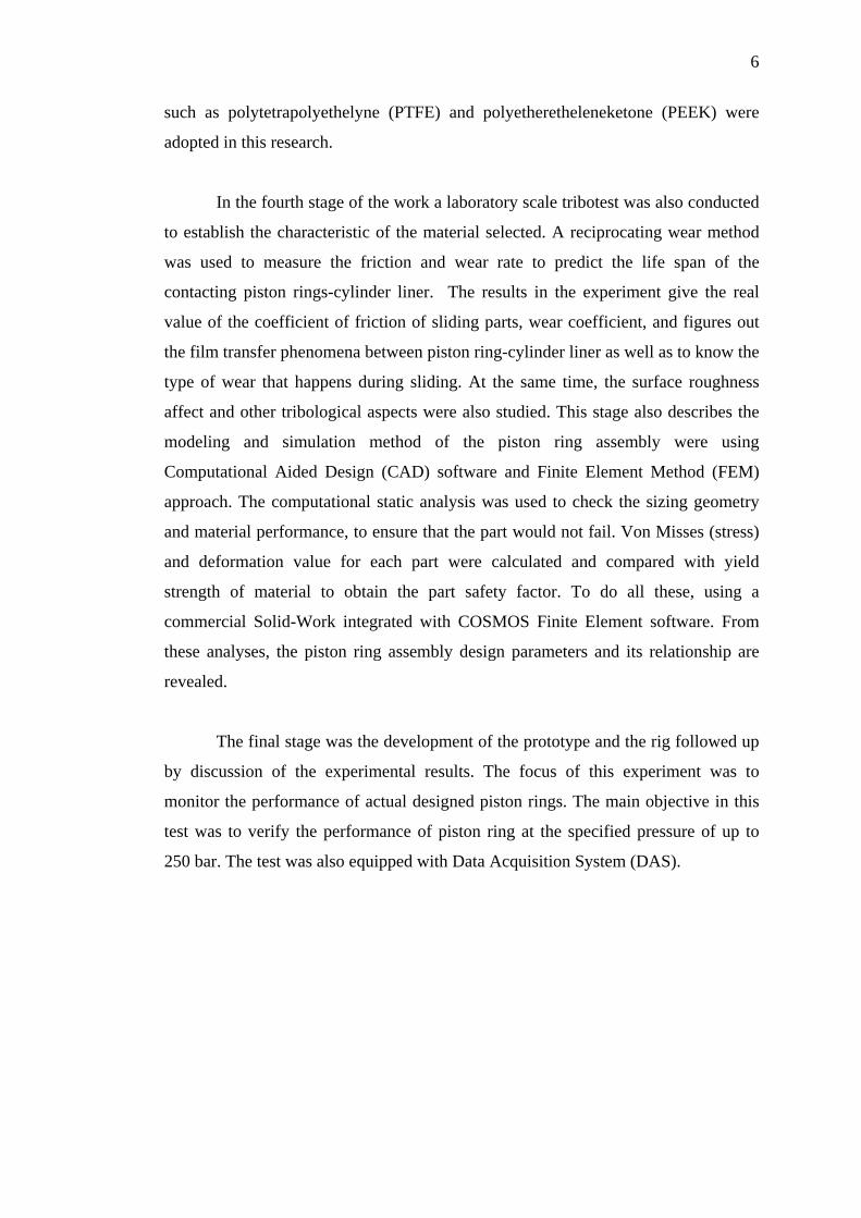
7
Literature Study
Concept Development
Reverse Engineering
Design of Piston Ring Assembly (PRA)
Figure 2.1 Flowchart of Research Phases
END
Design & Analysis Tribotest Material Selection
Modeling & Simulation
Development Prototype & Rig
Prototype Test
START
Data Analysis

CHAPTER II
LITERATURE REVIEW
2.1 Introduction
In a reciprocating compressor, the system of piston rings assembly is one of
the most important and critical aspect. Approximately 60% of the frictional forces
caused in the reciprocating machines are the result from this tribological system of
piston ring as reported by Todsen and Kruse (1982). In order to achieve efficient
sealing, the piston ring should make a good fit with both the cylinder wall and the top
or bottom of the piston ring groove. Piston rings for current reciprocating compressor
have to meet all the requirements of a dynamic seal for a linear motion that operates
under demanding pressure, thermal and chemical conditions. In general, the
following requirements for a set of piston rings assembly can be identified as:
• Low friction, for supporting a high power efficiency rate
• Low wear of the ring, for ensuring a long operational lifetime
• Low wear of the cylinder liner, for retaining the desired surface texture of the
liner
• Emission suppression, by limiting the flow of crankcase oil to the combustion
chamber
9
• Good sealing capability and low blow-by for supporting the power efficiency
rate
• Good resistance against thermal, chemical attacks and hot erosion
• Reliable operation and cost effectiveness for a significantly long period at
time
2.2 Oil Lubricated and Non Lubricated Cylinder
Since the cylinder assemblies of reciprocating compressors must be designed
relative to their lubrication, the nomenclature used to describe and classify the types
of cylinder construction likewise refers to lubrication. The classifications most
commonly used are depicted from Bloch and Hoefner (1996):
(i). Lubricated Cylinder Construction.
The lubricated cylinder assembly is the conventional cylinder construction,
which has a liquid lubricant introduced directly into the cylinder and piston
rod packing in sufficient amounts to provide a lubrication film between the
mated parts. The gas from the lubricated cylinder is contaminated with the
lubricant, normally a hydro-carbon or a synthetic oil.
(ii). Mini-Lube
A partially lubricated cylinder construction with oil feed to the cylinders
reduced to at least one-third of that for a lubricated cylinder. Teflon as self-
lubricated material is used on the piston and for the pressure packing. The
aims of Mini-Lube construction are to reduce the amount of oil carried within
the exit gas and to reduce contamination of systems.
(iii). Micro-Lube
No lubrication to the cylinder from conventional oil feed, but some oil enters
the cylinder from migration along the piston rod. Teflon as self-lubricated
material is used on the piston and for the pressure packing. The oil is usually
10
removed by scraper rings, which allows oil migration along the piston rod.
The reasons for this construction are the same as for Mini-Lube, except that
the system receives an even smaller amount of oil.
(iv). Non-Lube or Oil-Free Cylinder Construction
No lubrication reaches the cylinder. A longer distance piece between piston
rod and cylinder is used to separate the crosshead guide from the cylinder.
This necessitates a longer piston rod on which a "collar" or oil deflector is
installed. This collar prevents oil migration along the rod and into the
cylinder.
The conventional lubrication of piston ring in an industrial gas compressor or
combustion engine usually used lubricated cylinder construction as explained above.
Oil as lubricant functions to reduce the friction-wear between piston ring and
cylinder liner. Oil also has the functions as a media to assist the transfer of heat from
piston to cylinder wall and to control oil consumption.
Piston ring assembly forms a ring pack, which usually consists of 2–5 rings,
including at least one compression ring. The number of rings in the ring pack
depends on the engine type, but usually comprises 2–4 compression rings and 0–2 oil
control rings. For example, fast speed four-stroke diesel engines have 2 or 3
compression rings and a single oil control ring. The oil control rings used in diesel
engines are two-piece assemblies and the spark ignited engine of oil control rings can
be of three-piece assemblies. In addition to the general compression rings and oil
control rings, there are scraper rings which have the tasks for both sealing and
scraping off the oil from the liner wall, see the Figure 2.1.
Many applications in industrial gas compressor, the oil that sips into the gas
flow system is generally acceptable but, equally, there are a wide range of uses of
compressed gases (in the food industry, brewing and pharmaceutical industry, for
breathing air, chemical and petroleum industry, etc) where the presence of
lubricating oil is completely unacceptable.

11
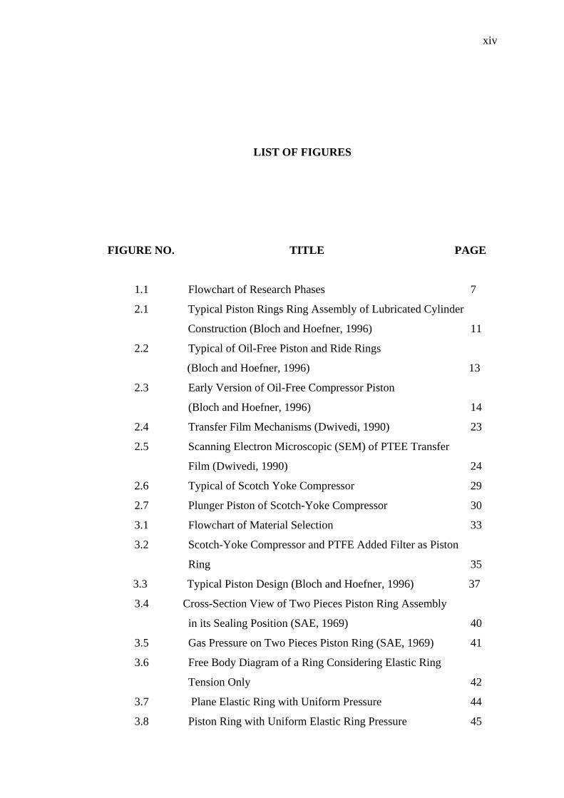
Figure 2.1 Typical piston rings ring assembly of lubricated cylinder construction (Bloch and Hoefner, 1996)
The oil contamination during compression can create the sludge that surely
will reduce performance of a compressor and in some cases can possibly lead to a
combustion of the system if the oil is passed into the machine. For these and other
reasons, oil-free cylinder construction has become increasingly popular as describes
by Bloch and Hoefner (1996). Further brief discussions on the advantages and
disadvantages of oil lubricated compared to oil-free/ non-lubricated compressor are
given in Table 2.1.
In the non-lubricated or oil-free construction, piston and piston ring assembly
there is no oil film to wet the piston, so the metallic piston must be kept off the
cylinder bore by other means or else serious damage will result. Note that this is the
difference between lubricated and non-lubricated principle.
Consequently, the material for the oil-free piston ring must have certain
characteristics to fulfill the function of piston ring as have been explained before.
The popular materials used in oil-free compressor application are carbon, graphite
and Polytetrafluoroethelyne (PTFE). These materials usually called as the self-
lubricating material, where by the process of steady wear can release a loose carbon/

12
graphite material which acts as a lubricant between the piston and liner. This
phenomenon will be described further in the next section.
Table 2.1 Lubricated versus oil-free/ non-lubricated (Hanlon, 2001):
Lubricated Oil-free/ Non-lubricated
Advantages Increased piston ring life Low to nil contamination of discharged
gas Allowed use of metallic ring Reduced overall lubrication requirements Air cooling or non-cooling system Less discharged gas filtration needed
Higher pressure ratios and discharge
temperature Reduced routine maintenance
Fewer stages necessary in some case
Higher operating speed Reduced capital cost Longer overhaul intervals Disadvantages Oil contamination of discharge Higher maximum discharge temperatures
Oil deposits in pressure vessels reducing
capacity to store gas Reduced piston ring and rod packing life
Oil contamination of on board vehicle
equipment Lower pressure ratios Increased vehicle emissions More stages may be necessary Higher compressor oil consumption Increased capital cost
Increased maintenance on lubrication
system Lower operational speeds
Increased noise levels with air cooled
compressors
In order to ensure the durability, there are in some design where the oil-free
piston rings are to serve a large cross-sectional area, it consists a minimum of two
piston rings and one rider ring. The rider ring acts as the support piston weight and as
a bearing surface to transmit the piston side loading into the cylinder wall. A typical
piston rings assembly for oil-free compressor is equipped completely with piston
rings, rider rings, and rod packing. Figure 2.2 illustrates and shows the location of
these critical components.

13
Figure 2.2 Typical of oil-free piston and rider rings (Bloch and Hoefner, 1996)
In the conventional non-lubricated compressor, the piston is kept off the
cylinder wall by a guide ring which is referred to as a wear, or rider ring. This rider
ring is of a low friction material, such as carbon or Teflon, and of low unit loading
relative to the piston weight. The outside diameter of this piston ring is smaller than
that of the piston in the lubricated compressor model, this creates clearance between
the piston outside diameter and the cylinder bore. This clearance allows for rider
band wear before metal contact occurs with the cylinder bore. The rider ring is either
a solid or a split configuration; its size is determined by piston assembly weight only
and is independent of operating pressures.
2.3 History and Development of Oil-Free Reciprocating Compressor
Bloch and Hoefner (1996) described the history of oil-free compressor in the
industrial compressor. Around mid 1930s, the first high pressure 2000 Psi oil-free air
compressor was made by using carbon piston rings used the water as lubrication. In
following years, many single and multi stage compressors were made by using
carbon as the wearing material for both piston rings and rider rings. This carbon
piston ring construction is shown in Figure 2.3. This was a “non-floating” type
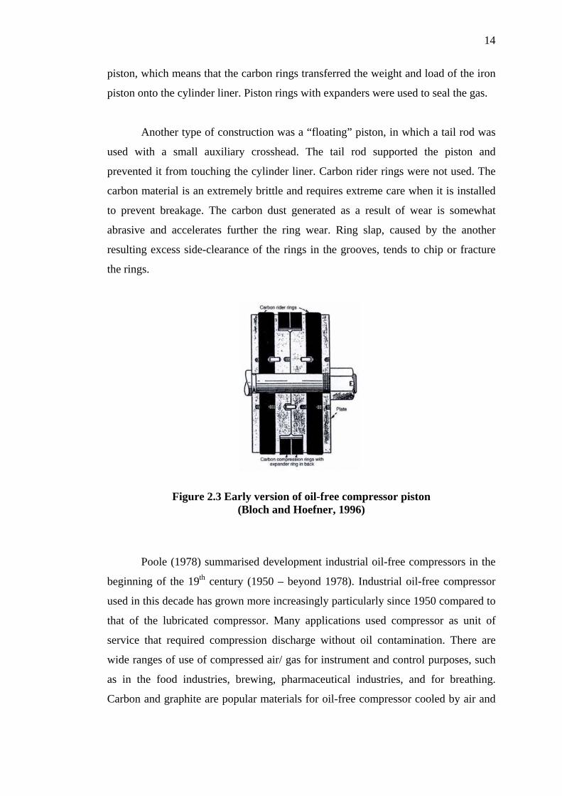
14
piston, which means that the carbon rings transferred the weight and load of the iron
piston onto the cylinder liner. Piston rings with expanders were used to seal the gas.
Another type of construction was a “floating” piston, in which a tail rod was
used with a small auxiliary crosshead. The tail rod supported the piston and
prevented it from touching the cylinder liner. Carbon rider rings were not used. The
carbon material is an extremely brittle and requires extreme care when it is installed
to prevent breakage. The carbon dust generated as a result of wear is somewhat
abrasive and accelerates further the ring wear. Ring slap, caused by the another
resulting excess side-clearance of the rings in the grooves, tends to chip or fracture
the rings.
Figure 2.3 Early version of oil-free compressor piston (Bloch and Hoefner, 1996)
Poole (1978) summarised development industrial oil-free compressors in the
beginning of the 19th century (1950 – beyond 1978). Industrial oil-free compressor
used in this decade has grown more increasingly particularly since 1950 compared to
that of the lubricated compressor. Many applications used compressor as unit of
service that required compression discharge without oil contamination. There are
wide ranges of use of compressed air/ gas for instrument and control purposes, such
as in the food industries, brewing, pharmaceutical industries, and for breathing.
Carbon and graphite are popular materials for oil-free compressor cooled by air and
15
water. Because of the safety and environmental aspects before 1950, the compressor
just operated no higher than 7-8 bar.
From the use of compressor with a single stage, single acting and double
acting with multistage compression, the later compressor manufacture has gradually
accepted more and more of the responsibility for the total installation. Especially in
industrial air compressor, the engineering development of oil-free type compressor
with higher reliability is also reported. With the use of air-drying equipment to
extract the water vapor remaining inside the delivered air from-and-after the cooler,
the manufacturer can provide the package of compressed air installation that delivers
air freely from any significant contamination and they were capable of operating
with minimum maintenance and maximum reliability.
Since the 20th century, construction and development of oil-free compressor
have been challenged by international requirement of the recognized standard of
American Petroleum Institute (API 618) “Reciprocating Compressors for Petroleum,
Chemical, and Gas Industry Services” dated June 2005:
“ The equipment (including auxiliaries) covered by this standard shall be
designed and constructed for minimum service life of 20 years and an
expected uninterrupted operation of at least 3 years…”
Wilson (2000) presented a paper discussed the advanced materials for the oil-
free reciprocating compressor. In this paper, he and Compressor Product Company
(CPI) company’s had developed new materials for oil-free compressor parts
especially for piston, rod packing ring, and guider ring. Investigated on field
compressor applications with various gasses, the successful development of oil-free
compressor answered the API 618 challenge. The common development of oil-free
gas compressor that has been using in industries:

16
Table 2.2 Common examples of oil-free gas compressor
applications (Wilson, 2000):
Gas Application Examples
Ammonia Refrigerant, chemical processing agent
Air PET bottle blowing, air separation, pneumatic instruments
Argon Welding, lamps
Butane Fuel gas, chemical manufacturing
Carbon Dioxide Carbonation of drink, cooling, fire extinguishing
Carbon Monoxide Chemical processing, ore reduction, fuel gases
Ethylene Plastic manufacture, antifreeze
Helium Welding, lamps, cryogenic, balloons
Hydrogen Refining, food manufacture, ammonia synthesis
Isobutene Plastic and chemicals manufacture
Methane Fuel gas, chemicals manufacture
Natural gas Fuel gas
Nitrogen Inert gas purging, ammonia synthesis,
Oxygen Steel and chemicals manufacturing, breathing systems
Propane Fuel gas, refining
Propylene Plastic and chemical manufacturing
From Table 2.2, some of the gases the compressor in a “bone dry” condition.
This bone-dry condition means that the gas demanded a prior drying process
especially if the gas is exposed to a lower temperature during the liquid-gas phase
change. For example, liquid natural gas is stored below -160ºC.
Existing reciprocating compressor, with carbon-filled Polytetrafluoroethelyne
(PTFE) piston rings, guide rings and packing rings fitted to compressor that can
handle those dry gases are summarised in Table 2.2, have been found to be able to
operate between 500 hours to 6000 hours duration before the next maintenance.
Developments of material were introduced by CPI manufacture from special polymer
alloy, (a code CPI 184). Using this material CPI 184 the oil-free compressor can
17
operate with pressure ranging from 0.5 to 36 Mpa and majority of gases are in a
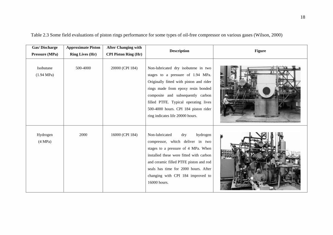
bone-dry condition. Some field evaluations of piston rings performance for some
types of oil-free compressor on various gases are summarised in Table 2.3:
2.4 Material development for oil-free piston ring
Traditionally, piston rings for reciprocating motion were made from the cast
iron. Cast iron is combined with steel as cylinder liner, so that lubrication with oil
becomes necessary to reduce friction and also as part of the cooling system.
Lubrication oil film also has the functions to prevent a leakage between piston ring
and cylinder liner. However, for oil-free reciprocating motion, the oil function is
replaced by the solid lubricant film which can be transferred during the sliding
between piston ring and the smooth surface of the steel cylinder liner. In
reciprocating compressor, the system of piston-ring-cylinder liner or Piston Ring
Assembly (PRA) is important assemblies to be concerned. The high pressure,
temperature, friction, and wear during compression process make PRA becomes very
important for design and should be optimized for achieving a minimum of power and
compression losses.
Maczek and Wolek (1994) investigated the technology of air compression
using oil-free reciprocating compressor in which cylinder and piston rings are
specially designed and modified by manufacturers for a stable operation. Two
compressors of air compression have been redesigned using a cylinder made of
aluminum alloy and cylinder bearing surface that covered by 80 micron-meter
electrolytic oxide layer of aluminum oxide. Piston rings were specially designed and
made from the modified PTFE (15% of graphite and 2.5% molybdenum disulphide).
Air pressure of the both compressor types 1 and 2 specification raised up until 0.2
MPa and 1450 rpm rotational speed. Type 1 is a single stage, twin cylinder confined
lubrication. Whereas for type 2 is single stage, one cylinder and oil-free condition.
18
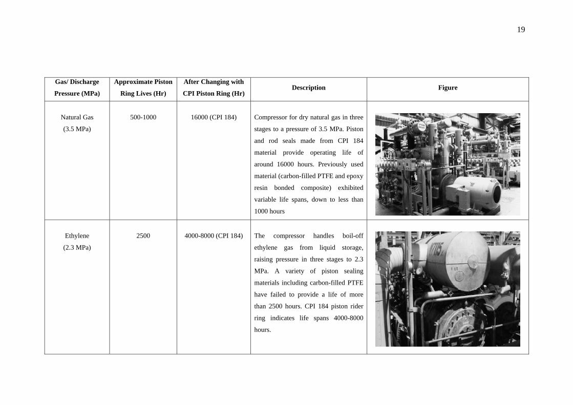
Table 2.3 Some field evaluations of piston rings performance for some types of oil-free compressor on various gases (Wilson, 2000)
Gas/ Discharge
Pressure (MPa)
Approximate Piston
Ring Lives (Hr)
After Changing with
CPI Piston Ring (Hr) Description Figure
Isobutane
(1.94 MPa)
500-4000
20000 (CPI 184)
Non-lubricated dry isobutene in two
stages to a pressure of 1.94 MPa.
Originally fitted with piston and rider
rings made from epoxy resin bonded
composite and subsequently carbon
filled PTFE. Typical operating lives
500-4000 hours. CPI 184 piston rider
ring indicates life 20000 hours.
Hydrogen
(4 MPa)
2000
16000 (CPI 184)
Non-lubricated dry hydrogen
compressor, which deliver in two
stages to a pressure of 4 MPa. When
installed these were fitted with carbon
and ceramic filled PTFE piston and rod
seals has time for 2000 hours. After
changing with CPI 184 improved to
16000 hours.
19
Gas/ Discharge
Pressure (MPa)
Approximate Piston
Ring Lives (Hr)
After Changing with
CPI Piston Ring (Hr) Description Figure
Natural Gas
(3.5 MPa)
500-1000
16000 (CPI 184)
Compressor for dry natural gas in three
stages to a pressure of 3.5 MPa. Piston
and rod seals made from CPI 184
material provide operating life of
around 16000 hours. Previously used
material (carbon-filled PTFE and epoxy
resin bonded composite) exhibited
variable life spans, down to less than
1000 hours
Ethylene
(2.3 MPa)
2500
4000-8000 (CPI 184)
The compressor handles boil-off
ethylene gas from liquid storage,
raising pressure in three stages to 2.3
MPa. A variety of piston sealing
materials including carbon-filled PTFE
have failed to provide a life of more
than 2500 hours. CPI 184 piston rider
ring indicates life spans 4000-8000
hours.

20
Gas/ Discharge
Pressure (MPa)
Approximate Piston
Ring Lives (Hr)
After Changing with
CPI Piston Ring (Hr) Description Figure
Nitrogen
(2.17 MPa)
2000
16000 (CPI 184)
Non-lubricated dry nitrogen in two
stages to a pressure of 2.17 MPa.
Originally fitted with piston and rider
rings made from epoxy resin bonded
composite and subsequently carbon
filled PTFE. Typical operating life
2000 hours. CPI 184 piston rider ring
indicates life span16000 hours.

21
Bottomley (1994) presented the history of Polytetrafluoroethelyne (PTFE) for
self-lubricated material in reciprocating machine. The history of PTFE began April
6th 1938 to present at Du Pont’s Jackson Laboratory in New Jersey, United States of
America. The main advantage of this material is it can perform a self-lubrication
because the properties of PTFE is based on the process of steady wear, which
releases that loose carbon/ graphite material that acted as a lubricant between piston
and liner. The PTFE piston ring also deposits an adherent counter-surface of PTFE
on to the liner wall during the compression process (adhesion wear). To improve the
performance of PTFE the additives or fillers such glass, carbon, graphite, bronze and
molybdenum disulphide are normally used. By careful formulation and selection of
filler materials, the self-lubrication properties of the filled PTFE materials have been
improved to give the longer life-times, especially in gas compressors. Parallel
detailed analysis using simulation such as Finite Element Method of piston ring
material has also promised more optimization of the selected materials.
To make the material stronger and more resistant against the tendency of
creeping, the fiber or bronze fillers can be added as fillers. Bottomley (1994) also
reported the synopsis of development of the filled polymeric compound. Fillers are
often used in a combination, particularly between carbon and graphite. Carbon for
dry gas usage, at low and cryogenic dew point, is good and useful as addition of
specific fillers. The basic fillers used in the development of oil-free gas compressor
are glass, carbon, graphite, molybdenum disulphide (MoS2) and bronze:
• Glass
Glass which is the most widely used filler is the milled glass fiber. Glass
improves the creep resistance of PTFE at all temperatures. It is chemically stable and
improves the wear rate and friction characteristics of PTFE.
• Carbon
Carbon has excellent resistance to chemical attack, except in oxidizing
environments such as concentrated acid, where glass performs better. Carbon adds to
the creep resistance, increases the hardness and raises the thermal conductivity of
PTFE. In general service carbon filled compounds have more excellent wear

22
properties, particularly when combined with graphite. The combination of the above
properties makes the carbon-graphite filled PTFE becoming a standard choice for oil-
free operation in industrial compressor. During the mid to late of the eighties, carbon
in fiber form began to emerge as a successful filler, particularly in dry gases. Carbon
fiber changes the physical properties in a similar way to glass fiber. Generally,
material that has less carbon fiber than glass fiber is needed to achieve the same
effect. Carbon fiber is chemically inert so that it can be used to replace the glass
filled compounds that fail to resist it. Additional advantages also accrue: higher
thermal conductivity, lower thermal expansion coefficient, and lightness. Carbon
fiber filled materials have less wear during contact with most metals and are less
abrasive on mating surface.
• Graphite
Graphite is a crystalline modification of high purity carbon. It has excellent
wear properties, particularly against soft metals, and display good load carrying
capability in higher speed contact applications. Graphite is also chemically inert, and
can be used in combination with other fillers. Filled PTFE containing carbon and
graphite has one of the lowest coefficient of friction of the filled PTFE compounds.
• Molybdenum Disulphide (MOS2)
Molybdenum Disulphide is used in low percentages and normally only with
other fillers. MOS2 adds to the hardness and stiffness of the PTFE and also reduces
friction.
• Bronze
The additional of high percentage of bronze powder to PTFE has the result of
higher thermal conductivity and better creep resistance than most other filled
PTFE’s. Single stage air compression is a successful example of the bronze filled
PTFE but it should not be used for sour gas applications as the pressure of Hydrogen
Sulphide (H2S) in the sour gas attacks the bronze.
Radcliffe (2005) explained the transfer film of the self-lubricating material.
During the sliding process, the PTFE material is sheared away from the piston rings,
and some of it are deposited into the cylinder liner to form a transfer film, as it is

23
shown in Figure 2.4. Further subsequent sliding takes place between PTFE and
PTFE, for which the coefficient of friction is extremely low. This phenomenon
ensures a considerable longer life for the piston rings as well as for the liner
(Dwivedi, 1990).
Figure 2.4 Transfer film mechanisms (Dwivedi, 1990)
In general, simultaneous process of piston ring wear and formation of transfer
film is a combination of tribochemical and mechanical reaction phenomena.
Depending on the type of fillers, surface roughness of sliding material and gas
conditions, a range of reaction can take place in the transfer film so that the wear
behavior of a filled PTFE material varies with the gas conditions and the fillers used.
To show how the wear affects on the piston ring or the cylinder liner, an image
captured by a Scanning Electron Microscopic (SEM) is shown in Figure 2.5.

24
Figure 2.5 Scanning Electron Microscopic (SEM)
of PTFE transfer film (Dwivedi, 1990)
2.5 Piston Rings Design
The studies on the kinematics and dynamics motion of the piston and piston
ring as function of the liner and piston geometry, surface quality, thermal and
thermodynamic boundaries have been done by Wrede (1978) and Haubner (2001).
Primary and secondary motions of the piston are used as boundary to simulate the
dynamic behaviour of the piston ring. Piston secondary movement is described by
the displacement of the piston normal to the liner and crank shaft axis and the tilt
angle around the pin axis. This secondary movement is influenced by two main
factors, geometrical and operational.
Under geometric factor the secondary movement are determined by the piston
axis deviation, eccentric centre of gravity of piston (near piston pivot point) and
distortion of liner axis to crankshaft axis, whereas gasses and mass forces are the
operational factor. Newer requirement for piston design that need to be addressed
includes light weight design, low friction loses, high wear resistance and lifetime
demands. Piston group is placed separate from the liner by the lubricated oil film.
25
Piston skirt will carry the inclination of the connected rod force. Skirt load
capabilities are determined by grinding of the piston, liner distortion, piston structure
stiffness, surface roughness between the piston and the liner including the liner
honing, crank train kinematics, masses or mass distribution, local liner, oil film
temperatures, oil quality and oil viscosity. Haubner has also listed out the technique
to reduce piston ring friction as follows:
• Increased of cylinder liner temperature
• Reduced of tangential forces in combination with reduced bore distortion
• Optimized ring geometry (friction behaviour is ruled by run in)
• Use of new materials with high resistance, durability and efficiency
• Reduced ring preload
• Reduced ring height
• Special ring design
• Reduced number of compression rings
• Reduced liner distortion
• Increased of liner temperature
• Low oil viscosity
Many studies and investigation have been reported in the literature in the
optimasitation of design at piston rings for engine and compressor. Ouwerkerk and
Theeuwes (1981) have been developed a test rig to determine the leakage and friction
in piston ring-liner of engine and gas compressor. A test rig was used in which the
friction was measured during the stroke and the gas leakage over a whole cycle.
Different shapes with o-ring backup methods and cut joints were tested in this
research. They reported that there were three possible leakage paths; gap between
piston and liner, rear side of the piston ring and joint cut of the piston ring.
Yong (1986) studied a method for predicting the sealing characteristics of
piston rings and evaluated the sealing effects of lubricating by oil and solid. He
developed the mathematical models of working cycle in a cylinder and the gas
leakage through piston rings. In oil-free compressor, there are three possible paths of
gas leakages through the rings; ring and surface of cylinder wall, rings and bottom of

26
slot of piston, and gaps of rings. The mathematical simulation of working cycle of
compressor is used to calculate pressures in cylinder, which has some proper
simplifications:
• Thermal parameters in suction and discharge plenums are constants
• No heat transfer in the cycle
• Gas leakage through piston rings is negligible
• No gas leakage through valves and the flow coefficient of valves are constant
• The working medium is ideal gas
2.6 Wear of Piston Ring
It is commonly assumed that the wear of piston rings proceeded according to
a mild mechanism of mild two-body abrasive wear against the cylinder liner, as
being expressed by the formulae presented by Gupta (2001), Kauzlarich and
Williams (2001) in the reality process of the wear is significantly more complicated.
The wear of piston rings and cylinder liners can be accelerated by three-body
abrasive wear due to the minor abrasive particles in the lubricating oil. The
contaminant particles caused by the three-body abrasive wear can originate from the
oil sump or from the combustion chamber.
For low wear rates, the wear volume of piston rings can be determined by
comparing the surface roughness between before and after the tests on the surface
roughness profiles or cross section profiles, Shuster et.al (1999). Alternatively, the
wear can be estimated from an analysis of the changes at relevant surface roughness
parameters that represented certain proportions of the piston ring face-surface area,
Sherrington and Mercer (2000). For high wear rates, the wear volume can be
determined from macro geometrical changes or mass loss.
Wilson (1990) investigated the materials for oil-free gas compressor,
especially for piston ring and rod packing material. In this paper, Wilson also

27
describes the wear process of self-lubricated materials. The process by the self-
lubricating sealing components (that provided their own lubrication and wear
resistance) can be described as a transfer mechanism. This phenomenon involves a
complex mechanical deposition of two frictional materials. Results in a thin transfer
film of some identical materials become intimately attached into the counter-surface
(cylinder liner). Once this transfer film has been established, the rate of wear of the
component can be relatively stable, ideally it is reduced to almost negligible rates.
Wilson also observed the influence of wear parameters:
• Piston mean sliding speed
• Specific loads (on rider rings)
• Gas pressures and temperatures
• Liner and rod surface finishes
• Cylinder cooling efficiency
• Gas cleanliness
Priest and Taylor (2000) presented the modeling and simulation of piston
ring-cylinder liner wear phenomenon. Wear of both piston rings and the cylinder
liner is perhaps the most difficult phenomenon to be fully implemented in a
calculation model. Wear parameters most certainly require empirical data. The time
required for conducting the simulation increases when the wear models are included
in the simulation software. In terms of simulation, the wear comprises the less
understood phenomena rather than for friction or lubrication. Even though wear
might be considered a minor factor in calculation models, it should be remembered
that the wear of a piston ring alters the ring profile. Therefore, wear is a phenomenon
to be included in a realistic model. Priest and Taylor have investigated piston ring
wear modeling. They pointed out that piston ring designs with emphasis on wear
resistance may be non-optimal if considering the lubrication and frictional properties.
Wear of the cylinder liner at a great extend is caused by the action of the
piston rings (Affenzeller and Gläser, 1996). Practical observations and theoretical
analyses correlate well in terms of the strongest wear of the cylinder liners by taking
place near to the top reversal point of the top piston ring, where the thermal,

28
chemical, erosive and abrasive conditions are the severest. High wear of the cylinder
liner is furthermore associated with the top reversal point of the second piston ring,
and (to a less extent) with the bottom reversal points of the piston rings. Carbon
deposits above the ring pack on the piston may significantly increase the cylinder
liner wear in sliding processes.
2.7 Computer Modeling and Simulation
Dunaevsky (1999) investigated the fiction temperature generated by a piston
ring in a reciprocating oil-less air brake compressor. Many parameters that influence
prediction on the friction temperature are reciprocating motion of the piston, gas
load, piston ring geometry, thermophysical properties of the ring and the bore
material. The three dimensional diffusion-equations conducted to solve the
rectangular source of heat are involved in a reciprocating motion. The solution is
presented in an integral form, and the results are obtained using numerical
integration.
Shivakant and Krishna (2001) have presented a work on simulation of a
piston ring in a multi-body single cylinder internal combustion engine by using FEA.
Several studies, like hydrodynamic lubrication, blow-by, contact between ring and
liner and the piston secondary motions are important for performance evaluation and
design of piston rings. For their simulation model, they studied crankshaft,
connecting rod, piston, piston ring and liner. Explicit method that is well-suited for
condition at high-speed dynamic events, at short duration and at nonlinear contact is
used. By knowing the initial clearance and piston ring deformation, then the blow-by
can be predicted. Blow-by occurs if the ring liner-gap exceeds the oil film thickness.
Axial movement of the piston ring in the groove also contributes to the blow-by.
Fatigue failure needs to be considered since the piston ring is subjected to the cyclic
loading. The clearance between piston and liner is responsible for two secondary
motions, tilt and translational motion of the piston assembly that is perpendicular to
the piston pin and engine axes. The similar method is used by Dunaevsky (2001).
29
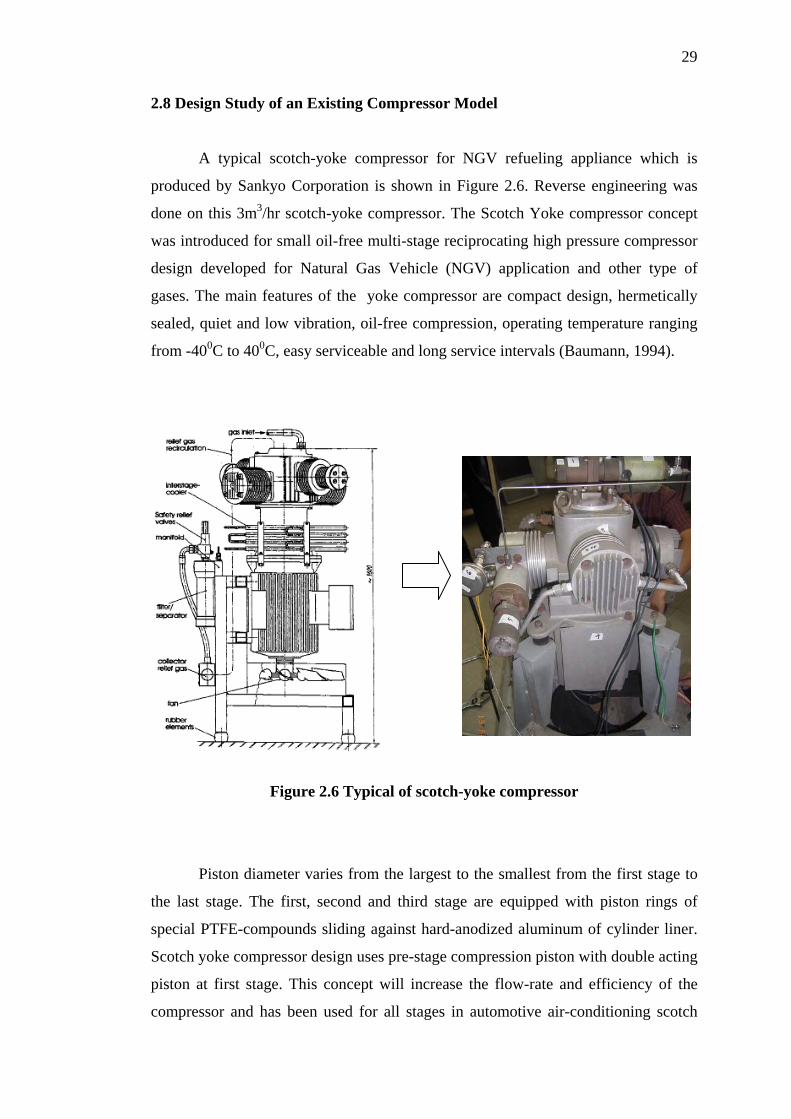
2.8 Design Study of an Existing Compressor Model
A typical scotch-yoke compressor for NGV refueling appliance which is
produced by Sankyo Corporation is shown in Figure 2.6. Reverse engineering was
done on this 3m3/hr scotch-yoke compressor. The Scotch Yoke compressor concept
was introduced for small oil-free multi-stage reciprocating high pressure compressor
design developed for Natural Gas Vehicle (NGV) application and other type of
gases. The main features of the yoke compressor are compact design, hermetically
sealed, quiet and low vibration, oil-free compression, operating temperature ranging
from -400C to 400C, easy serviceable and long service intervals (Baumann, 1994).
Figure 2.6 Typical of scotch-yoke compressor
Piston diameter varies from the largest to the smallest from the first stage to
the last stage. The first, second and third stage are equipped with piston rings of
special PTFE-compounds sliding against hard-anodized aluminum of cylinder liner.
Scotch yoke compressor design uses pre-stage compression piston with double acting
piston at first stage. This concept will increase the flow-rate and efficiency of the
compressor and has been used for all stages in automotive air-conditioning scotch

30
yoke compressor ((Riegger, 1990); (Baumann, 1994); (Nishikawa and Nishikawa,
1998 and 2000); and (Bauman and Conzett, 2002)). Pre-stage compression piston is
only suitable for large piston diameter size and unsuitable for small piston diameter
size for second stage and above in multistage scotch yoke compressor.
Some methods have been used to increase the durability in the scotch-yoke
compressor as presented by Nishikawa et al (1998). Grease with good heat resistance
and little scattering property was selected for the sliding parts in the yoke
mechanism. Anti-wear materials which were suitable for the sliding movement in a
non-lubricated condition were used for the piston ring at the lower pressure stages.
For the high pressure stages where the piston diameter size was small and not
suitable for the piston ring usage, plunger piston concept was used. Labyrinth
grooves on the plunger piston surface keeps leakage to minimum. Rolling support
was used at the piston to guarantee the piston free from side-force. The plunger
piston floats freely in the cylinder with a small well defined gap, as can be seen in
Figure 2.7.
Figure 2.7 Plunger piston of scotch-yoke compressor
31
Baumann and Conzett (2002) reported that the clearance gap of 4 to 6 µm in
diameter is needed for the sealing between the plunger piston and the cylinder liner.
The thermal coefficient of expansion for the plunger piston and the cylinder liner
material also need to be small and similar due to this small gap. The materials for
plunger piston and cylinder liner used for gases like air, nitrogen, natural gas and
carbon dioxide were hard-metal and ceramic respectively. Gases like helium, argon,
dry nitrogen and hydrogen require special material combinations and coatings for the
plunger piston-cylinder liner combinations. They have also shown that the leakage
flow through the clearance gap which constitutes a few percent of the gas flow rate is
laminar and depending on the piston geometry, the clearance dimension, the piston
velocity and the type of gas.
CHAPTER III
THEORY OF PISTON RING ASSEMBLY 3.1 Material
This chapter discusses the overall theory of the materials for piston ring
assembly, which comprises of piston, piston ring and cylinder liner materials.
Material selection for piston ring assembly is very essential to know the
characteristic of the material to assist in the design and for the success of the
operation.
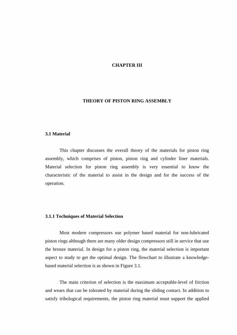
3.1.1 Techniques of Material Selection
Most modern compressors use polymer based material for non-lubricated
piston rings although there are many older design compressors still in service that use
the bronze material. In design for a piston ring, the material selection is important
aspect to study to get the optimal design. The flowchart to illustrate a knowledge-
based material selection is as shown in Figure 3.1.
The main criterion of selection is the maximum acceptable-level of friction
and wears that can be tolerated by material during the sliding contact. In addition to
satisfy tribological requirements, the piston ring material must support the applied
33
load without significant distortion under the operating conditions, practically to
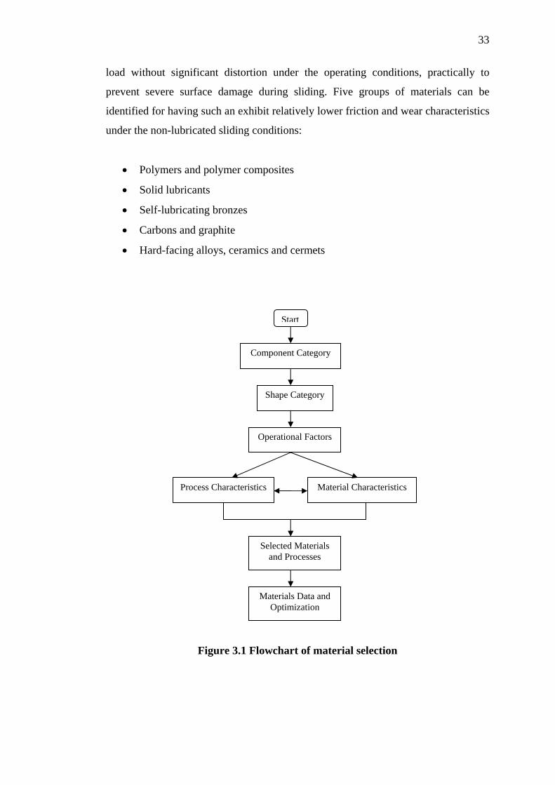
prevent severe surface damage during sliding. Five groups of materials can be
identified for having such an exhibit relatively lower friction and wear characteristics
under the non-lubricated sliding conditions:
• Polymers and polymer composites
• Solid lubricants
• Self-lubricating bronzes
• Carbons and graphite
• Hard-facing alloys, ceramics and cermets
Start
Component Category
Shape Category
Operational Factors
Process Characteristics Material Characteristics
Selected Materials and Processes
Materials Data and Optimization
Figure 3.1 Flowchart of material selection

34
The difference of mechanical, thermal and tribological properties of the
materials satisfies a wide range of the compressor’s operating specifications.
Moreover they included values of material capability to carry out continuous
operation in extremes of temperature, from -250°C to in excess of 500°C, at
pressures in excess of 1000 bar and at sliding speeds over 10 m/s.
Theoretically, there are at least three different techniques to obtain the
optimum material may be selected: (Smith, 1994)
1. The ‘Classical Procedure‘ using functional analysis and property
specification.
2. The ‘Imitative Procedure’ which consists the finding on what and which
material has been used for a similar component.
3. The ‘Comparative Procedure’ which consists of some postulates that the
component could be made firstly from some cheap and well-understood
engineering material, then assessing some ways such of each material’s
performance that would be possibly inadequate and from this step arriving
progressively to the right material.
The Classical Procedure is the only one that being universally applicable and
it is essential, even when procedures 2nd or 3rd are followed to check the findings by
functional analysis and property specification. However, the Classical Procedure is
expensive, time consuming and requires a considerable amount of prototype testing
to ensure that no critical requirement or essential property has been over-looked.
The Imitative and Comparative Procedures, if it’s applicable will provide
invaluable shortcuts, except for a greater expenditure of time and money, moreover
it will help to ensure that no essential parameter has been over-looked. The optimum
material for Piston Ring assembly (PRA), the imitative procedure was conducted in
this study. The reverse engineering was also carefully observed and investigated with
similar conditions, especially the case of the Scotch Yoke gas compressor with 245
bar discharge pressure. On the other hand, besides material selection the literatures of
the four stages and oil-free lubrication were studied in the same time and will be
compared at this study.
35
3.1.2 Piston Ring Design and Material
Based on the discussion in chapter II, the non-lubricated piston ring material
can be applied for gas compressor to ensure the purity of the gas during compression
process. Durability of non-lubricated compressor depends on anti-wear ability of
piston rings, as well as on the sufficient strength of the ring required at a high
pressure condition. To withstand the high pressure of 250 bar, several piston rings
are needed in order to reduce the load and friction per ring.
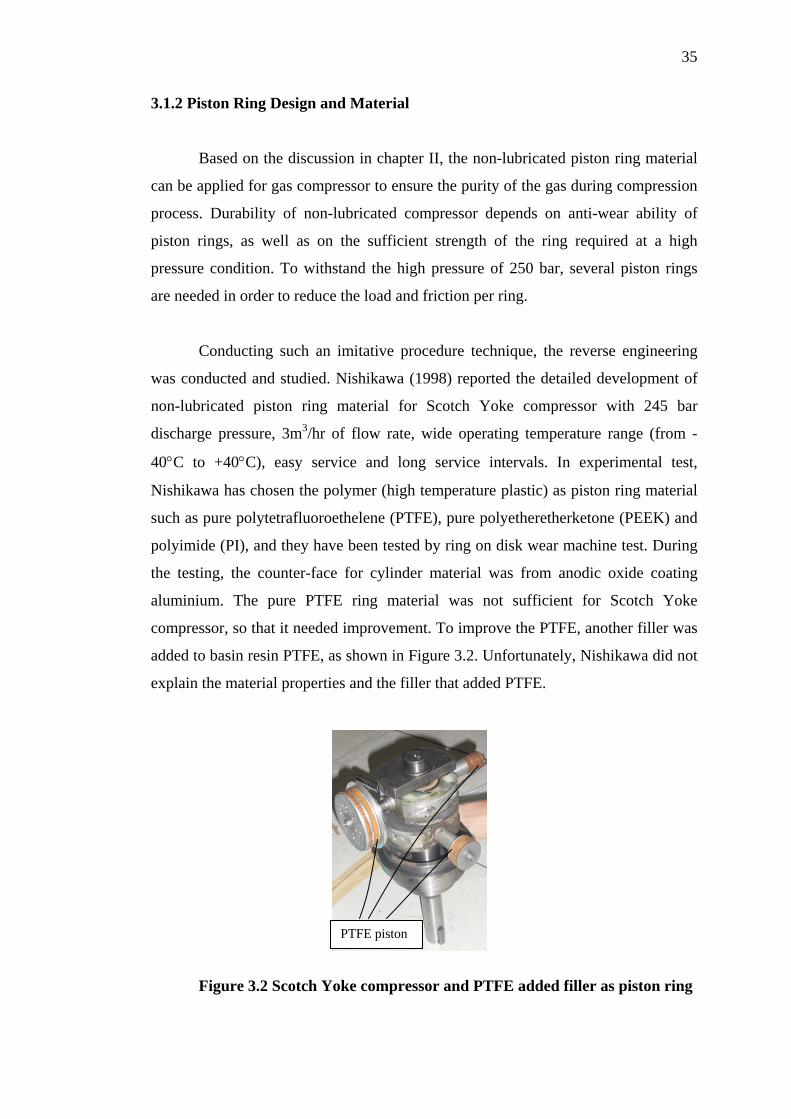
Conducting such an imitative procedure technique, the reverse engineering
was conducted and studied. Nishikawa (1998) reported the detailed development of
non-lubricated piston ring material for Scotch Yoke compressor with 245 bar
discharge pressure, 3m3/hr of flow rate, wide operating temperature range (from -
40°C to +40°C), easy service and long service intervals. In experimental test,
Nishikawa has chosen the polymer (high temperature plastic) as piston ring material
such as pure polytetrafluoroethelene (PTFE), pure polyetheretherketone (PEEK) and
polyimide (PI), and they have been tested by ring on disk wear machine test. During
the testing, the counter-face for cylinder material was from anodic oxide coating
aluminium. The pure PTFE ring material was not sufficient for Scotch Yoke
compressor, so that it needed improvement. To improve the PTFE, another filler was
added to basin resin PTFE, as shown in Figure 3.2. Unfortunately, Nishikawa did not
explain the material properties and the filler that added PTFE.
PTFE piston
Figure 3.2 Scotch Yoke compressor and PTFE added filler as piston ring
36
However, this reverse engineering exercise provided the helpful guidance on
determining the basic material that suitable for higher pressure gas compressor this
exercise also gave ideas for solving some specific problems that possibly could arise
for similar type of application. Therefore, a successful test on a polymer based
material (PTFE and PEEK) was conducted and this material is selected for use as the
piston ring for the new HRA symmetrical wobble plate compressor. Another reason
for the selection is that the raw materials and the fillers are available locally at a
reasonable price.
3.1.3 Piston Design and Material
Commonly, the design and materials used for compressor pistons will vary
with the make, type, and application of the compressor. They are designed to take
into account a number of conditions:
• Cylinder bore diameter
• Discharge pressure
• Rotational speed
• Stroke
• Required piston weight
• Strength, for differential pressure and temperature
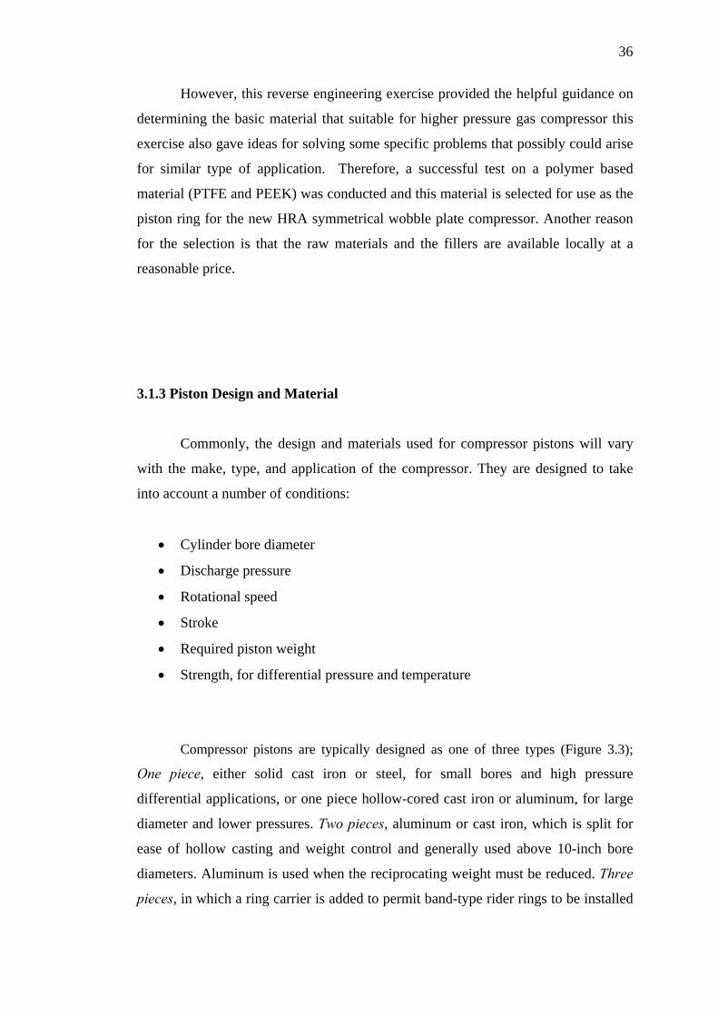
Compressor pistons are typically designed as one of three types (Figure 3.3);
One piece, either solid cast iron or steel, for small bores and high pressure
differential applications, or one piece hollow-cored cast iron or aluminum, for large
diameter and lower pressures. Two pieces, aluminum or cast iron, which is split for
ease of hollow casting and weight control and generally used above 10-inch bore
diameters. Aluminum is used when the reciprocating weight must be reduced. Three
pieces, in which a ring carrier is added to permit band-type rider rings to be installed
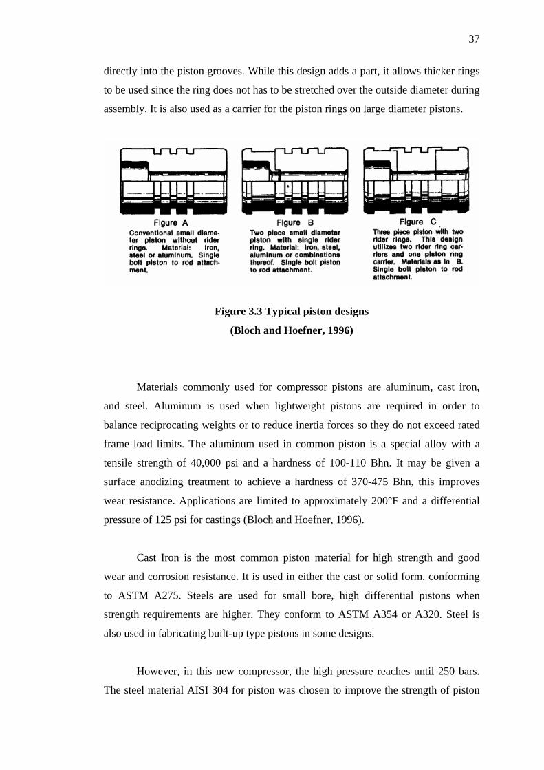
37
directly into the piston grooves. While this design adds a part, it allows thicker rings
to be used since the ring does not has to be stretched over the outside diameter during
assembly. It is also used as a carrier for the piston rings on large diameter pistons.
Figure 3.3 Typical piston designs
(Bloch and Hoefner, 1996)
Materials commonly used for compressor pistons are aluminum, cast iron,
and steel. Aluminum is used when lightweight pistons are required in order to
balance reciprocating weights or to reduce inertia forces so they do not exceed rated
frame load limits. The aluminum used in common piston is a special alloy with a
tensile strength of 40,000 psi and a hardness of 100-110 Bhn. It may be given a
surface anodizing treatment to achieve a hardness of 370-475 Bhn, this improves
wear resistance. Applications are limited to approximately 200°F and a differential
pressure of 125 psi for castings (Bloch and Hoefner, 1996).
Cast Iron is the most common piston material for high strength and good
wear and corrosion resistance. It is used in either the cast or solid form, conforming
to ASTM A275. Steels are used for small bore, high differential pistons when
strength requirements are higher. They conform to ASTM A354 or A320. Steel is
also used in fabricating built-up type pistons in some designs.
However, in this new compressor, the high pressure reaches until 250 bars.
The steel material AISI 304 for piston was chosen to improve the strength of piston
38
and design in one piece. These piston have various diameter sizes; 36mm, 25mm,
15mm, and 10mm for 1st stage, 2nd stage, 3rd stage and 4th stage respectively. The
detail piston design is given in Appendix A and groove size for each piston and rider
rings is given in Appendix B.
3.1.4 Cylinder Liner Design and Material
The liner constitutes an important tribological element as a sliding surface
against the piston and piston rings. For non-lubricated material, the cylinder liner can
commonly be made of hard steel metal or hard-anodised aluminium (Baumann,
1994). The cylinder liner surface can be coated with a hard chromium layer to
improve the wear resistance of the cylinder liners (Affenzeller and Gläser, 1996).
The surface roughness also has significant effect on the tribological performance of
piston rings. This surface roughness affect is discussed in Chapter V.
3.2 Design and Analysis
The theory of piston rings has been applied to design and analysis of the
piston ring assembly in the proposed compressor. Principally, piston ring assembly in
linear motion has similar theory for all reciprocating engine. For a new symmetrical
wobble-plate compressor, the piston ring is considered ideal and followed by other
assumed parameters, as follows:
1. Highest loading condition, maximum gas compression force at each stage
was used which is at the Top Dead Centre (TDC) condition.
2. Piston side force and vibration effect are negligible hence piston slides in
linear motion.

39
3. Temperature during compression is stable and the cooling system is working
perfectly.
4. There is no gas leakage (blow-by)
5. The piston, piston ring, and cylinder liner are cylindricity (no out of
roundness).
3.2.1 Loads and Forces Acting On Piston Ring
In gasoline and diesel engine, the rings are generally of split-type
compression metal rings. When they are placed in the grooves of the piston, a
moving seal being formed between the piston and cylinder liner. Compression rings
normally of two or more pieces are located near the top of the piston, in order to
block the downward flow of gases from the compression chamber. For piston using
the lubricant, the oil rings must be placed below the compression rings to prevent or
control the passage of lubrication oil into the compression or combustion chamber.
In order to achieve efficient sealing, the piston ring should make a good fit
with both the cylinder liner and the top or bottom of the piston ring groove. The
radial fit is achieved if the inherent spring forces the ring, together with the pressure
of the working medium acting from behind the ring. In the case of a compression
engine, the working medium is the combustion gas. The gas pressure determines the
axial position of the ring within its groove, meanwhile the inertia and friction force
can alternate between the top and bottom of the groove as illustrated in Figure 3.4
(Society of Automotive Engineers (SAE), 1969).
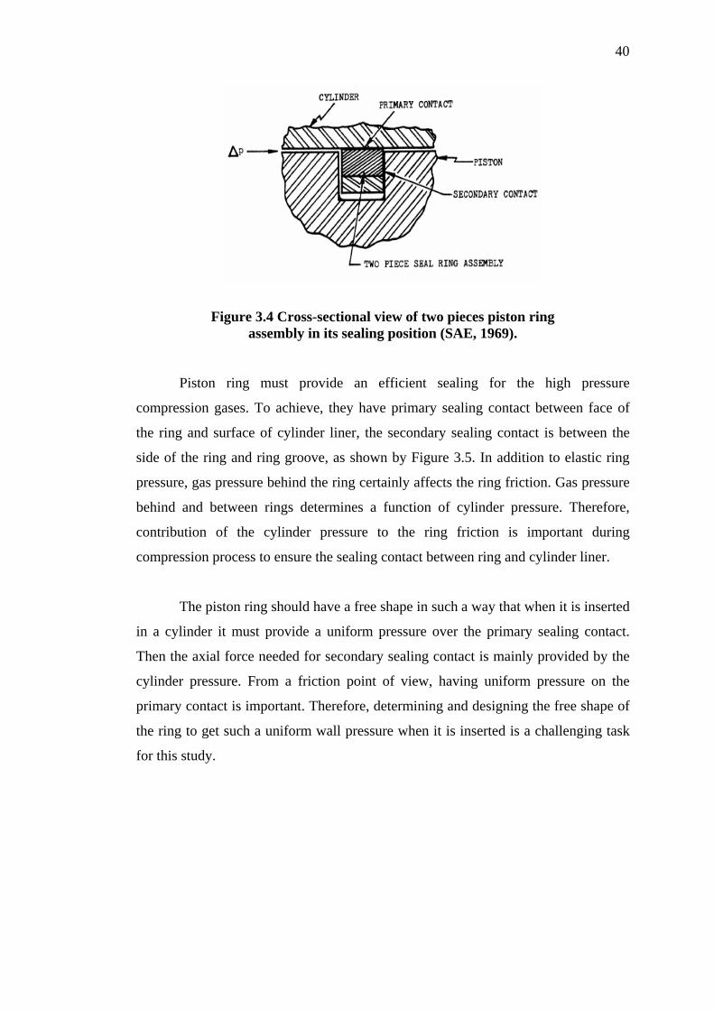
40
Figure 3.4 Cross-sectional view of two pieces piston ring assembly in its sealing position (SAE, 1969).
Piston ring must provide an efficient sealing for the high pressure
compression gases. To achieve, they have primary sealing contact between face of
the ring and surface of cylinder liner, the secondary sealing contact is between the
side of the ring and ring groove, as shown by Figure 3.5. In addition to elastic ring
pressure, gas pressure behind the ring certainly affects the ring friction. Gas pressure
behind and between rings determines a function of cylinder pressure. Therefore,
contribution of the cylinder pressure to the ring friction is important during
compression process to ensure the sealing contact between ring and cylinder liner.
The piston ring should have a free shape in such a way that when it is inserted
in a cylinder it must provide a uniform pressure over the primary sealing contact.
Then the axial force needed for secondary sealing contact is mainly provided by the
cylinder pressure. From a friction point of view, having uniform pressure on the
primary contact is important. Therefore, determining and designing the free shape of
the ring to get such a uniform wall pressure when it is inserted is a challenging task
for this study.
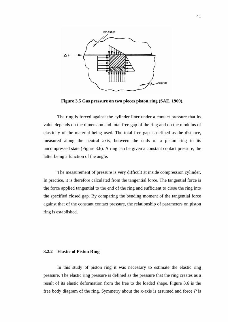
41
Figure 3.5 Gas pressure on two pieces piston ring (SAE, 1969).
The ring is forced against the cylinder liner under a contact pressure that its
value depends on the dimension and total free gap of the ring and on the modulus of
elasticity of the material being used. The total free gap is defined as the distance,
measured along the neutral axis, between the ends of a piston ring in its
uncompressed state (Figure 3.6). A ring can be given a constant contact pressure, the
latter being a function of the angle.
The measurement of pressure is very difficult at inside compression cylinder.
In practice, it is therefore calculated from the tangential force. The tangential force is
the force applied tangential to the end of the ring and sufficient to close the ring into
the specified closed gap. By comparing the bending moment of the tangential force
against that of the constant contact pressure, the relationship of parameters on piston
ring is established.
3.2.2 Elastic of Piston Ring
In this study of piston ring it was necessary to estimate the elastic ring
pressure. The elastic ring pressure is defined as the pressure that the ring creates as a
result of its elastic deformation from the free to the loaded shape. Figure 3.6 is the
free body diagram of the ring. Symmetry about the x-axis is assumed and force P is
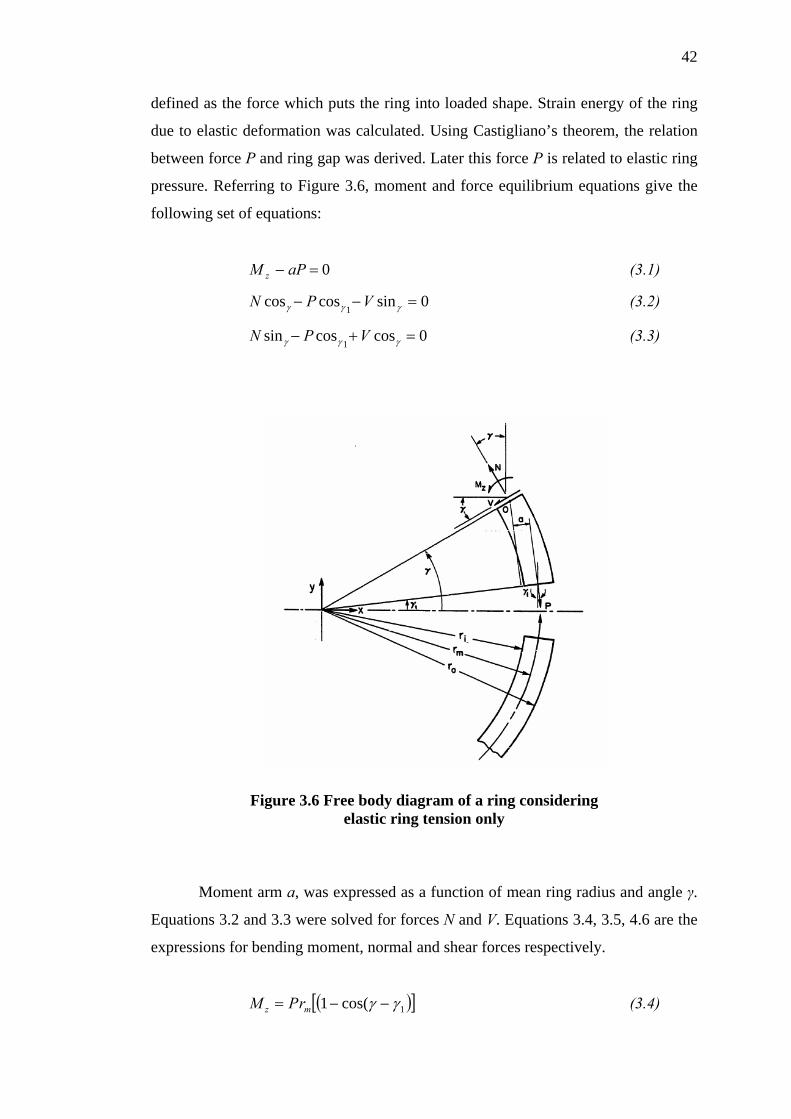
42
defined as the force which puts the ring into loaded shape. Strain energy of the ring
due to elastic deformation was calculated. Using Castigliano’s theorem, the relation
between force P and ring gap was derived. Later this force P is related to elastic ring
pressure. Referring to Figure 3.6, moment and force equilibrium equations give the
following set of equations:
(3.1) 0=− aPM z
0sincoscos1
=−− γγγ VPN (3.2)
0coscossin1
=+− γγγ VPN (3.3)
Figure 3.6 Free body diagram of a ring considering
elastic ring tension only
Moment arm a, was expressed as a function of mean ring radius and angle γ.
Equations 3.2 and 3.3 were solved for forces N and V. Equations 3.4, 3.5, 4.6 are the
expressions for bending moment, normal and shear forces respectively.
([ 1cos(1 )]γγ −−= mz rPM (3.4)
43
( )γγγγ sinsincoscos11
+= PN (3.5)
( )γγγγ sincoscossin11
+= PV (3.6)
Strain energy due to bending moment, normal force and shear force are given
by the following equations:
dxIE
MUzm
zb ∫=
2
21 (3.7)
dxAE
NUrm
n ∫=2
21 (3.8)
dxAG
vUr
s ∫=2
53 (3.9)
Castigliano’s theorem gives the deflections due to bending moment δb,
normal δn, and shear δs , forces. Following are the equations for deflections:
P
Ubb ∂
∂=δ (3.10)
P
Unn ∂
∂=δ (3.11)
P
U ss ∂
∂=δ (3.12)
The principal of superposition may by used to calculate total deflection δt:
snbt δδδδ ++= (3.13)

44
In terms of free, n and loaded q, ring gaps, total deflection is given by
Equation 3.14:
( qnt −=21δ ) (3.14)
Concentrated force P is not a function of x. This means that partial
differentiation with respect to force P can be performed before integration. It was
assumed that Ar, Em, G and Iz in equations 3.7 through 3.9 were constant and angle γ1
was zero. Integrations were performed with these assumptions. Equations 3.13 and
3.14 were used to derive the expression for force P.
( )
⎥⎦
⎤⎢⎣
⎡+
−
−=
z
m
rm
m
Ir
Ar
EqnP
23
1012172
2υπ (3.15)
For simplicity, elastic ring pressure was assumed to be uniform around the
ring. Figure 3.7 shows any elastic plane ring with an arbitrary shape loaded by a
uniform pressure P.
Figure 3.7 Plane elastic ring with uniform pressure
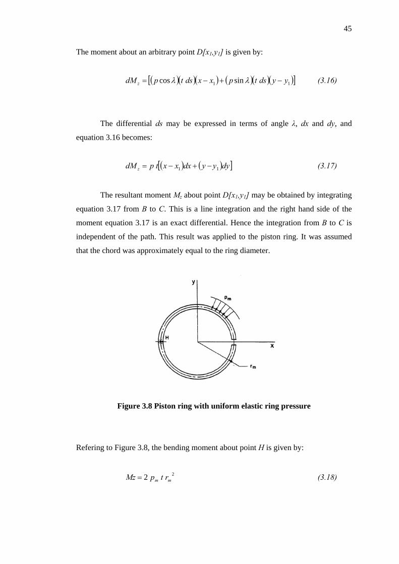
45
The moment about an arbitrary point D[x1,y1] is given by:
( )( )( ) ( )( )( )[ ]11 sincos yydstpxxdstpdM z −+−= λλ (3.16)
The differential ds may be expressed in terms of angle λ, dx and dy, and
equation 3.16 becomes:
( ) ( )[ dyyydxxxtpdM z 11 ]−+−= (3.17)
The resultant moment Mz about point D[x1,y1] may be obtained by integrating
equation 3.17 from B to C. This is a line integration and the right hand side of the
moment equation 3.17 is an exact differential. Hence the integration from B to C is
independent of the path. This result was applied to the piston ring. It was assumed
that the chord was approximately equal to the ring diameter.
Figure 3.8 Piston ring with uniform elastic ring pressure
Refering to Figure 3.8, the bending moment about point H is given by:
(3.18) 22 mm rtpMz =

46
Force P, which puts the ring into the same loaded shape, should create the
same bending moment:
(3.19) prMz m2=
Equation 4.18 and 4.19 were solved for the pressure pm:
m
m rtpp = (3.20)
It may be noted that the pressure given by the equation 3.20 is at mean ring
radius. Elastic ring pressure between the ring face and bore are proportional to ring
radius and is given by:
o
e rtpp = (3.21)
Equation 3.15 was used to calculate force p from ring geometry and material.
Elastic ring pressure was obtained from equation 3.21.
3.2.3 Piston Ring Forces
The forces that act on piston rings can be divided into two categories: axial
and radial forces. Axial forces determine the axial position of the piston ring at
different stages of the piston cycle. Radial forces determine whether a piston ring
collapses inward.
There are three primary forces that could influence the piston ring’s dynamics
include inertia, pressure and friction. The relative effects of theses forces on piston
rings are highly dependent on the operating conditions, such at certain high piston
speeds and low load, the inertia forces become more dominant than the pressure

47
forces. The opposite is also true; pressure forces are more dominant than inertial
forces at lower speeds and high loads. Frictional forces even at low speed and low
loads, do not have very much influences over the ring motion.
3.2.3.1 Inertial Force
The inertial force, Fl can be given simply as:
Fl = -m.a (3.22)
Where m is the mass of the ring and a is the axial acceleration of the ring. If
the ring is in contact with the piston groove, the ring’s axial acceleration is the same
as the piston. Pressure and friction forces would determine the ring’s acceleration if
the ring is floating in the piston groove.
3.2.3.2 Pressure Force
The pressure force, Fp acting on the bottom and top of the piston rings can be
modeled as;
Fp = P(r).A (3.23)
where P(r) is the pressure magnitude as a function of radius, and A is the
ring’s surface area. It was assumed that the pressure dropped linearly from the outer
to inner ring surface. The ring’s surface area A is;
A = π (D2 – d2) (3.24)
48
where D is the bore diameter and d varies depending upon the position of the
ring. If the ring is seated at the bottom of its groove, then d is the bore diameter
minus two times of the ring width. If the ring is touching the top of its groove, then d
is the piston diameter.
3.2.3.3 Friction Force
The friction forces, Ff between the piston’s ring face and cylinder liner can
be approximated by the semi-empirical equation (Mid –Michigan Research, 1998):
⎟⎟⎠
⎞⎜⎜⎝
⎛+=
pFDtpFf ax
axµν
τπ 8.4))(( (3.25)
Where p is the pressure behind the ring, tax is the axial width of the ring, Fτ is
the force due to ring tension, µ is the kinematics coefficient of friction and υax is the
ring’s axial velocity.
3.3 Ring Flutter
This "fluttering" motion occurs because of the pressure and inertial forces
continually alternate dominantly as the gas-flow’s paths change due to the ring
motion. Although the relative magnitude of the friction force is much less than either
the pressure forces or inertial forces, it becomes an important factor when the
pressure and inertial forces are nearly equal.
When pressure and inertial forces on a piston ring are close in magnitude, the
piston ring will have a tendency to oscillate axially faster in its groove. In the

49
instance in which ring flutter occurs near the end of the compression stroke, inertial
and pressure forces move the ring to the top of its groove. If the ring moves to the top
of its groove, it will floats and thus a flow path is opened between the ring bottom
and the groove bottom. As the ring reaches the top of its groove, the increasing
pressure forces at the end of the compression stroke can push the ring back down.
Before the ring is properly seated at the bottom of its groove. Gas can pass-through
behind the floating ring's groove and equalizing the pressure both the above and
below the ring. The inertial force then causes the ring to return again to the top of the
groove. This motion then can be repeated itself, impairing the ring's sealing
objective.
Friction actually acts beneficially during the presence of conditions favorable
to ring flutter. Since friction forces oppose any ring motion, they also dampen these
ring flutter oscillations and help to inhibit conditions that would initiate the
phenomenon. Although friction causes the piston ring wear and cylinder liner wear,
its very limited presence often improves ring stability. In some instances, ring flutter
can be a contributing factor to another unwanted ring behavior of the so-called ring
collapse. Further, ring flutter is sometime the practical result of ring collapse and is
to be an indication that ring collapse is likely to be identified. Ring collapse will be
explained in detail in the next section.
3.4 Ring Collapse
Ring collapse is an undesirable phenomenon in which the piston ring moves
radially. This is when the ring face being separated from the cylinder wall and
creating a large area in which compression gases can easily flow past. Ring collapse
is much more damaging to slower down performance than ring flutter. This condition
occurs when the forces acting on the ring face exceeded the combined forces
between the ring tension and the gas pressure behind the ring. Conditions favorable
for ring collapse usually coincide with high engine speeds and low engine load.
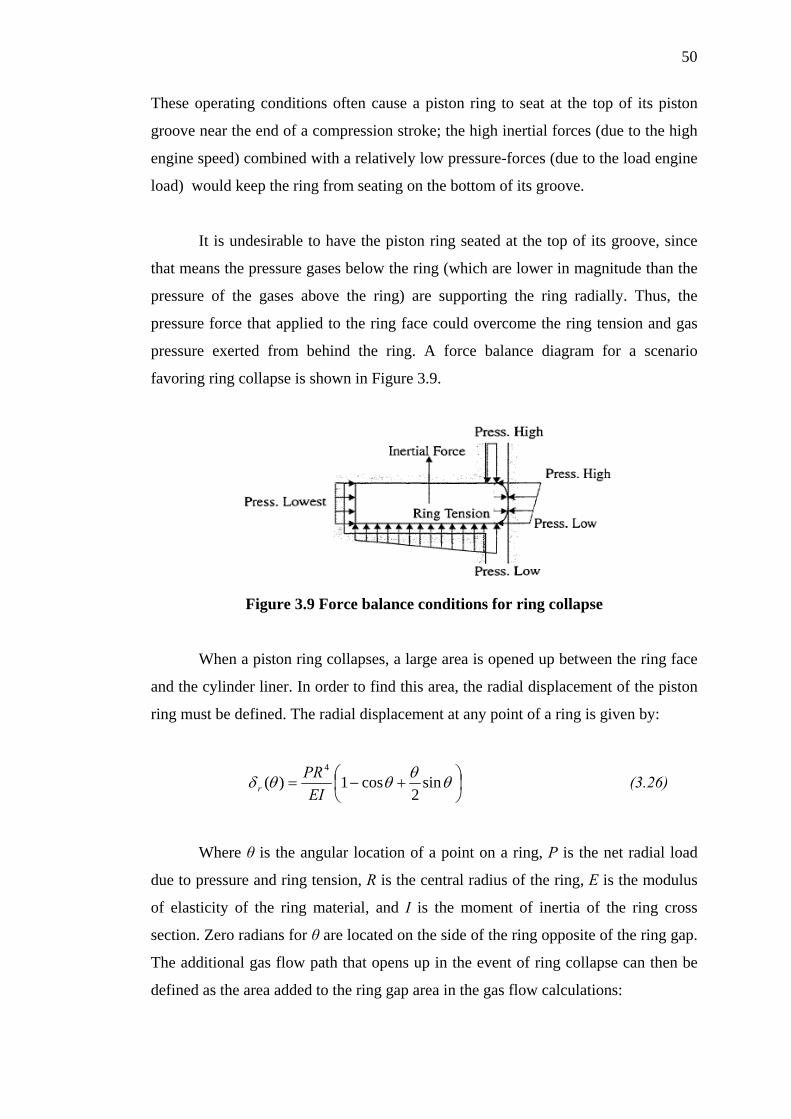
50
These operating conditions often cause a piston ring to seat at the top of its piston
groove near the end of a compression stroke; the high inertial forces (due to the high
engine speed) combined with a relatively low pressure-forces (due to the load engine
load) would keep the ring from seating on the bottom of its groove.
It is undesirable to have the piston ring seated at the top of its groove, since
that means the pressure gases below the ring (which are lower in magnitude than the
pressure of the gases above the ring) are supporting the ring radially. Thus, the
pressure force that applied to the ring face could overcome the ring tension and gas
pressure exerted from behind the ring. A force balance diagram for a scenario
favoring ring collapse is shown in Figure 3.9.
Figure 3.9 Force balance conditions for ring collapse
When a piston ring collapses, a large area is opened up between the ring face
and the cylinder liner. In order to find this area, the radial displacement of the piston
ring must be defined. The radial displacement at any point of a ring is given by:
⎟⎠⎞
⎜⎝⎛ +−= θθθθδ sin
2cos1)(
4
EIPR
r (3.26)
Where θ is the angular location of a point on a ring, P is the net radial load
due to pressure and ring tension, R is the central radius of the ring, E is the modulus
of elasticity of the ring material, and I is the moment of inertia of the ring cross
section. Zero radians for θ are located on the side of the ring opposite of the ring gap.
The additional gas flow path that opens up in the event of ring collapse can then be
defined as the area added to the ring gap area in the gas flow calculations:
51
(3.27) ∫=π
θδ0
2 RdA r
Substituting Equation (3.26) into Equation (3.27), and solving the integral yields:
EIPRA
53π= (3.28)
Under the circumstance that the ring end gap clearance is small, it is possible
that the radial displacement may be restricted due to the ends of the ring butting. To
find the maximum flow area that can occur between the ring face and the cylinder
liner, consider the area occupied by the piston ring, if its end clearance is zero.
Before finding the area, the effective ring parimeter, Peff could be calculated by using
equation:
endgapeff xDP −= π (3.29)
where D is the bore diameter (the original diameter of the outer ring surface)
and xendgap is the end gap clearance. An effective ring outer diameter Deff could be
derived from Equation (3.29) as:
π
endgapeff
xDD −= (3.30)
The area occupied by the ring, Aring is simply:
4
)( 2eff
ring
DA π= (3.31)
The maximum flow area, Amax is by definition to be:
(3.32) ringbore AAA −=max
52
where, 4
2DAboreπ
=
So Equation (3.32) can be simplified in term of end gap clearance and bore diameter
as:
DxA endgap21
max = (3.33)
3.5 Gas Leakage on Piston Rings
The high pressure variance in cylinder has great significance to decide gas
leakage. However, some past workers when calculating gas leakage often take the
pressure in cylinder as average value within a cycle or use the pressure variance in a
theoretical cycle as original data that makes it impossible to calculate the
instantaneous pressure distribution between rings and gas leakage through each ring.
Although sometimes the actual pressure in a cylinder is used, the data frequently
comes from measured value, and the use of some mathematical equations to predict
the leakage on piston ring is important in knowing the sealing characteristics of
piston rings and to carry out an optimal design (Yong et. al, 1986).
Predicting gas leakage during operation is very complicated and difficult to
measure. Theoretically, estimations may be used for some of the solutions, such as in
an oil-free gas compressor where there are three possible paths of gas leakage
through the rings as Figure 3.10 shows: (a) Between the rings and the surface of the
cylinder liner, (b) Between the rings and the groove of the piston, and (c) Through
the gaps of rings. For the piston with several rings, the total leakage mass flow ( m& )
through the ring is:
cibiaii mmmm &&&& ++= (3.34)
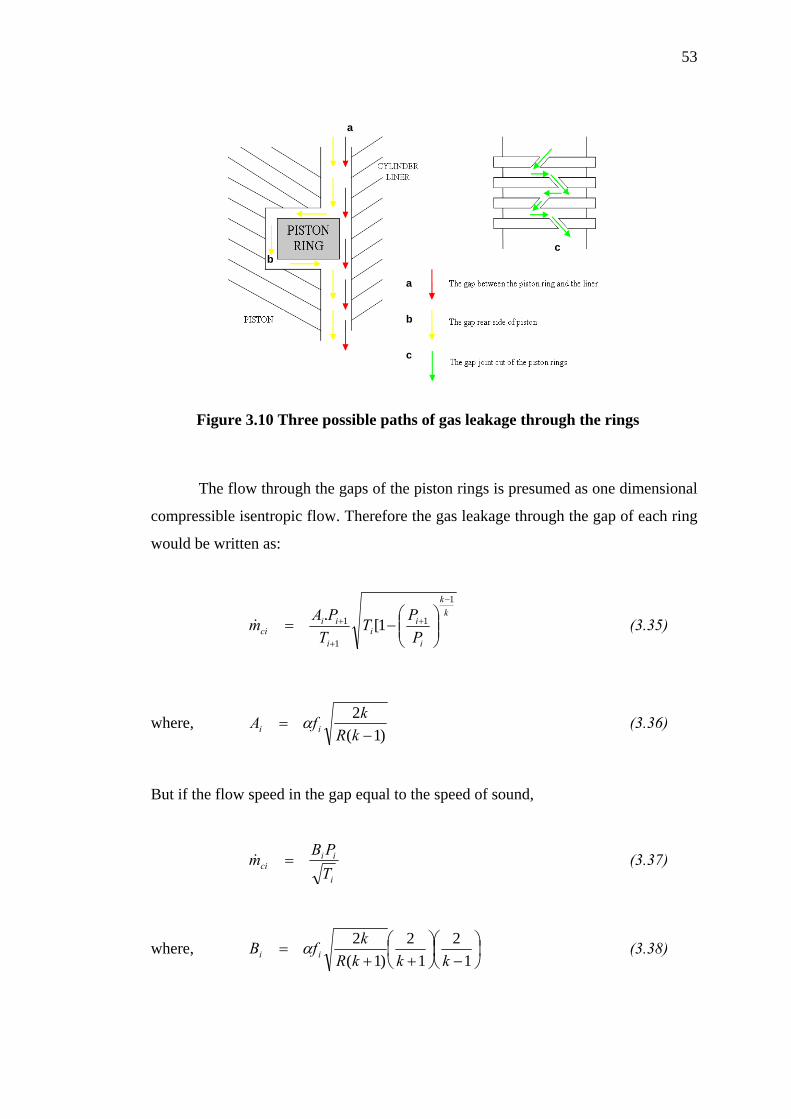
53
c
a
b
c b
a
Figure 3.10 Three possible paths of gas leakage through the rings
The flow through the gaps of the piston rings is presumed as one dimensional
compressible isentropic flow. Therefore the gas leakage through the gap of each ring
would be written as:
kk
i
ii
i
iici P
PTT
PAm
1
1
1
1 1[.−
+
+
+⎟⎟⎠
⎞⎜⎜⎝
⎛−=& (3.35)
where, )1(
2−
=kR
kfA ii α (3.36)
But if the flow speed in the gap equal to the speed of sound,
i
iici T
PBm =& (3.37)
where, ⎟⎠⎞
⎜⎝⎛
−⎟⎠⎞
⎜⎝⎛
++=
12
12
)1(2
kkkRkfB ii α (3.38)

54
The flows between the piston rings and the cylinder liner and between the
piston rings and the piston groove are considered as the flow in a thin clearance
between two smooth surfaces. This problem can be solved by using two dimensional
incompressible viscous laminar flow theories. Navier-Stokes equation was used to
predict the leakage between the rings and the cylinder liner ( ), and the leakage
between the rings and the piston groove ( ):
aim&
bim&
hTRppDm
i
iiaai µ
π24
)( 21
23+−∂
=& (3.39)
⎟⎠⎞
⎜⎝⎛
−
−∂= +
bDDTR
ppm
i
iibbi
2ln12
)( 21
23
µ
π& (3.40)
now, h
DC24π
= (3.41)
and, ⎟⎠⎞
⎜⎝⎛
−
=
bDD
E
2ln12
π (3.42)
The total leakage through the ring is thus:
i
iibak
k
i
ii
i
iii TR
ppECP
PT
TPA
mµ
)(1[
. 21
2331
1
1
1 +
−
+
+
+ −∂+∂+⎟⎟
⎠
⎞⎜⎜⎝
⎛−=& (3.43)
This formula which predicts a flow leakage through piston rings is usually
used for the butt joint type of piston rings. Several types of cut joints were designed
to minimise leakage. Scarf joint and step-cut joint were a more popular shapes for the
use in high-pressure oil-free compressors. These joints are either more easily cut,
installed and removed than compared with the gastight joint construction that costs
up to twice as much. In accordance with the sealing function required, piston ring
joints can be shaped to any degree of complexity within the bounds determined by
the material properties and ring dimension. To minimise the leakage between piston

55
ring cylinder liners, backup springs could be attached behind the actual ring to give a
slight amount of pressure (1-3 bar) and assist the piston ring in establishing the initial
seal.
Butt Joint Scarf Joint Step-cut Joint
Gastight Joint Two-piece Joint
Figure 3.11 Various types of cut joints for piston rings
3.6 Wear of Piston Ring – Cylinder Liner
Wear defined as the removal of material from solid surfaces to be a result of
mechanical action. Wear due to sliding is usually a very slow process, it is very
steady and continuous. From the reciprocating motion of the piston ring against the
cylinder liner causes the wearing over the contact surface, as shown in Figure 5.1.
Generally, wear is caused by individual and combined effects among corrosion,
adhesion and abrasion (Chui, 2001). However, corrosive wear normally occurs in
cylinder of a combustion engine which produces the harsh exhaust gases. It is quite
reasonable to assume corrosive wear as negligible in a gas compressor.

56
Figure 3.12 Rubbing of two contact surface under microscopic view (Chui, 2001)
Already mentioned earlier the abrasive wear occurs when there are impurities
present at the contact surfaces. The impurities can come from atmospheric dust and
from the solid debris from corrosive and adhesive wear. When the impurities stay
between two contact surfaces, such as the piston ring and cylinder liner, the ratio of
asperity contact is increased.
Adhesive wear mainly affects parts of the piston ring where there is solid-to-
solid surface sliding contact between piston-piston ring-cylinder liners. The removal
of material takes a form of small particles which are usually transferred to the other
surface. For automotive engine, the adhesive wear is especially significant when the
engine was at the beginning of operation and was cold, due to insufficient oil in the
piston ring-cylinder liner. For non-lubricated piston ring, the adhesive wear is also
very significant because no oil as lubrication to decrease the debris of material. This
type of wear is the focus of discussion in this thesis.
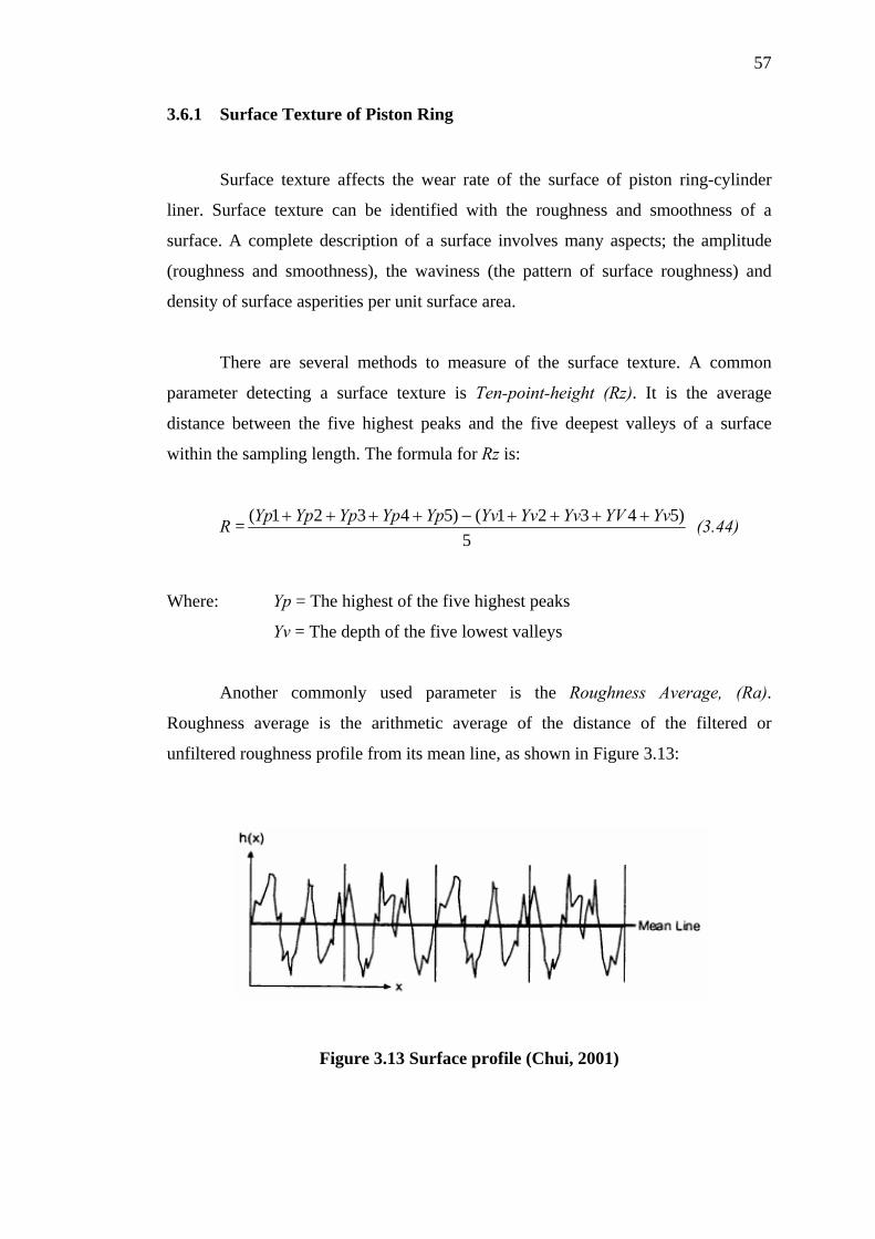
57
3.6.1 Surface Texture of Piston Ring
Surface texture affects the wear rate of the surface of piston ring-cylinder
liner. Surface texture can be identified with the roughness and smoothness of a
surface. A complete description of a surface involves many aspects; the amplitude
(roughness and smoothness), the waviness (the pattern of surface roughness) and
density of surface asperities per unit surface area.
There are several methods to measure of the surface texture. A common
parameter detecting a surface texture is Ten-point-height (Rz). It is the average
distance between the five highest peaks and the five deepest valleys of a surface
within the sampling length. The formula for Rz is:
R =5
)54321()54321( YvYVYvYvYvYpYpYpYpYp ++++−++++ (3.44)
Where: Yp = The highest of the five highest peaks
Yv = The depth of the five lowest valleys
Another commonly used parameter is the Roughness Average, (Ra).
Roughness average is the arithmetic average of the distance of the filtered or
unfiltered roughness profile from its mean line, as shown in Figure 3.13:
Figure 3.13 Surface profile (Chui, 2001)
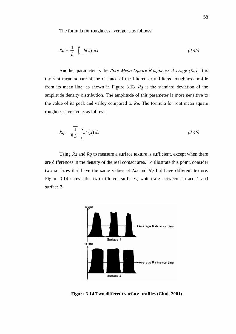
58
The formula for roughness average is as follows:
Ra = L1 dxxh
L
∫0 )( (3.45)
Another parameter is the Root Mean Square Roughness Average (Rq). It is
the root mean square of the distance of the filtered or unfiltered roughness profile
from its mean line, as shown in Figure 3.13. Rq is the standard deviation of the
amplitude density distribution. The amplitude of this parameter is more sensitive to
the value of its peak and valley compared to Ra. The formula for root mean square
roughness average is as follows:
Rq = L1 (3.46) ∫
L
dxxh0
2 )(
Using Ra and Rq to measure a surface texture is sufficient, except when there
are differences in the density of the real contact area. To illustrate this point, consider
two surfaces that have the same values of Ra and Rq but have different texture.
Figure 3.14 shows the two different surfaces, which are between surface 1 and
surface 2.
Figure 3.14 Two different surface profiles (Chui, 2001)

59
Applying Equation 3.45 and equation 3.46 will give same value of Ra and
Rq, even though these two surfaces are different. To distinguish surface 1 from
surface 2, another parameter is introduced: the Abbott Firestone Curve (AFC), which
is also called the Bearing Ratio Curve. It is a graphical representation of the bearing
ratio parameter, tp (length of bearing surface, expressed as a percentage of the
assessment length of a surface specimen, at a depth below the highest peak or a
selected distance from the average reference) in relation to the profile level. The
curve contains all the amplitude information of the surface profile. The AFC for
surface 1 and 2 is shown in Figure 3.15.
Figure 3.15 Surface representation using Abbott Firestone Curve (AFC)
(Chui, 2001)
From the Abbott Firestone Curve (AFC), the simple difference between the
two surfaces can be identified where surface 1 has lower amplitude density than
surface2.
The surface of the cylinder liner needs to be measured too. However, this step
can be avoided by assuming that the interaction of two surfaces can be simplified as
the interaction of one rough surface with a planar surface. The roughness value will
become the combination of two surface roughnesses.

60
Rz = Rz1 + Rz2 (3.47)
Where: Rz = the roughness of the combined surface profile
Rz1 = the roughness of surface 1
Rz2 = the roughness of surface 2
3.6.2 Wear Mechanism
Considering a small part of piston ring sliding on a cylinder liner as shown in
Figure 3.16 then this part of the piston ring can be assumed to be very small since the
curvature effect of the piston ring in a circumferential direction is negligible. The
amount of worn volume from the piston ring surface is calculated using the following
equation:
= V∂ sHFk ∂ (3.48)
Where:
V∂ = Incremental volume loss from contact surfaces
= Sliding distance of one surface with respect to another surface s∂
F = The total load applied to the piston ring surface while it is sliding
H = Combined hardness of the piston ring and cylinder liner
k = Wear coefficient
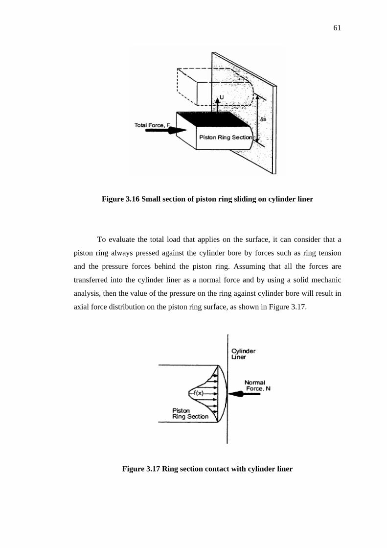
61
Figure 3.16 Small section of piston ring sliding on cylinder liner
To evaluate the total load that applies on the surface, it can consider that a
piston ring always pressed against the cylinder bore by forces such as ring tension
and the pressure forces behind the piston ring. Assuming that all the forces are
transferred into the cylinder liner as a normal force and by using a solid mechanic
analysis, then the value of the pressure on the ring against cylinder bore will result in
axial force distribution on the piston ring surface, as shown in Figure 3.17.
Figure 3.17 Ring section contact with cylinder liner

62
Applying Newton Second Law, one can deduce that:
(3.49) rFN =
where
(3.50) ∫= dxxfFr )(
In order to obtain f(x), the following assumptions are made:
• Linear elastic behavior of the piston ring material
• Modulus of elasticity of the cylinder liner is infinite
• Deformation is very small
• Shear stress on the piston ring is negligible compared to normal stress
With the assumptions above, the determination of force distribution of the
piston ring surface into the slices partition with the same width can be obtained as
illustrated in Figure 3.18. These slices are assumed to be completely separated from
each other since the normal stress is much higher than the shear stress.
Figure 3.18 Piston rings in slices partition

63
Using Hook’s law:
ii Eεσ = (3.51)
where: i
i
ll∆
=ε (3.52)
ii Afi σ= (3.53)
In order to obtain the forces for each slice, an arbitrary reference point is
assigned to start the process of evaluating the total force. The process continues with
the reference point being varied until the criterion of equation 3.49 is met. The final
value for the force of each slice will be used for the calculation of wear at each slice.
3.7 Symmetrical Multistage Wobble-plate Compressor
The new symmetrical multi-stage wobble-plate compressor has been
developed as a slow Home Refueling Appliance (HRA) and the prototype has been
patented in Malaysia under the title “Wobble Plate Compressor” with filing number,
PI 2005 5456 (Musa, 2005), Appendix D. The compressor design requirements for
this new compressor design are given in Table 3.1:
Table 3.1 Home Refueling Appliance (HRA) compressor design requirement:
Design requirement Value Inlet pressure 50 Psig (3.5Bar) Outlet pressure 3600 Psig (250 Bar) Gas flow-rate 1 m3/hr (slow refueling) Working gas Natural gas (gas compression index = 1.27) Operating speed 1000 rpm Overall Light, small, compact, low vibration and noise Lubrication method Oil-free cylinder wall
64
The initial symmetrical multi-stage wobble-plate compressor design
developed for the natural gas Home Refueling Appliance (HRA) is illustrated in
Figure 3.19. The main design features that differentiate this new symmetrical multi-
stage wobble-plate compressor from the existing wobble-plate compressor are the
use of the multi-size piston diameter for the multi-stage compression, the use of the
end-joint pairs as the connecting rod, forming symmetrical wobble-plate and piston
arrangement at each compressor ends and the use of oil-free lubrication system
inside cylinder assembly.
Those differences determined the unique mechanism of the compressor when
it was operated. The wobble-plate bearing has the functions as the sliding interface
between rotor and wobble-plate. The inner reel of wobble-plate bearing was tightly
fitted with rotor while the outer reel of the bearing was tightly fitted with the wobble-
plate. Through the assembly among the shaft, rotor, wobble-plate bearing and
wobble-plate, then each shaft rotation induced the wobble-plate wobbling motion.
Afterwards the wobbling motion was transferred to be the movement of piston
reciprocating via the certain connecting rod, which connects the piston and the
wobble-plate with a ball-joint connection between both ends of the connecting rod.
To prevent the connecting rod from being tangled together, the wobble-plate was
constrained from having rotated along with the rotor by using a single anti-rotation
mechanism which comprises the function of the anti-rotation ball, the anti-rotation
shoe and the anti-rotation rod.
Focusing on the gas flowing inside the new compressor, the reciprocating
motion of piston firstly compressed gas in the cylinder block, then gas was
transferred between each stage by using inter-stage piping. To achieve a higher
pressure, the multi-stage compression was necessary. Therefore, four stage
compressions were used together with four different sizes of piston, cylinder liner
and cylinder block. Fixed capacity configuration of the part was used for this new
compressor design, due to the fixed flow-rate requirement being required as it is
given in Table 3.2. In the following sub-sections, further details of initial components
for piston-piston and ring-liner design in this compressor will be outlined and its
design considerations will be explained.

65
Wobble-plate pin Wobble-plate bearing End plate bearing Piston Shaft
r Valve
LineFigure 3.19 Cross section of the symmetrical multi-stage wobble-plate compressor
More details on the typical piston assembly in this compressor design are
shown in Figure 3.20. The piston design was made different from that of the existing
piston used in an automotive air-conditioning using refrigerant compressor which
also uses wobble-plate compressor concept. The piston for higher pressure
compression tended to be more solid in design. The first-stage of the piston diameter
size was made as the largest one followed subsequently by the next stages and the
smallest piston diameter size is for the last stage. However, the number of piston ring
required for sealing at the piston for each stage would be different depending on the
increasing value of the compression pressure (Chlumsky, 1965).
Rotor
Wobble-plate
Anti-rotation ball
Anti-rotation ball
Shaft pin
Cylinder block

66
Connecting rod Piston pin Wobble-plate
pin Piston coupler
Bush PistonBush
Figure 3.20 Cross-section of piston assembly (First stage piston)
For connection among the parts throughout this compressor design, a pair of
self-lubricated end-joints, male and female were fastened altogether to make a single
connecting rod. Thread engagement length between the male and female end-joint
was adjusted according to the required connecting rod length. This threaded joint was
secured using nut and thread locker sealant. Bushes were used to position the end-
joint balls at the piston couplers and at the wobble-plate.
3.8 Installation of Piston Ring
Installations of piston ring into the groove were a tricky challenge during
assembly. Extreme difficulty was experienced when the un-cut piston ring needed to
be installed in a groove of a rigid piston. Usually the installation methods have used
either the split piston or cut the piston ring. But some disadvantages were found since
a split piston requires exact precision in its manufacture. The cut piston ring was
easily installed into the groove but the possible gas leakage (from blow-by) from the
gap of the cut which was very critical. Another method was to heat the piston ring in
a hot oil bath with 80˚C-100˚C of temperature. After the piston ring become soften, it
was easy to expand the ring into the groove and clamped until the material returning
to the original form. Yet this process was impractical as it changed the properties of
the material with respect to strength and therefore was not adopted.
Male end-joint
Female end-joint
End-joint ball
End-joint ball
Wobble-plate

67
In this study, another method was proposed, it is by using three pieces of
installation tools; installation sleeve, expanding sleeve, and sizing sleeve. All these
tools were made from a polymer material with good sliding characteristics and low
abrasiveness to avoid damage to the piston ring. The illustrated procedures are shown
at Figure 3.21. With the o-ring in position, the piston ring was inserted into the
installation sleeve as far as possible and then it was pushed further in by using the
expanding sleeve over the installation sleeve until the ring is rested in the groove
around the o-ring. The sizing sleeve is used to check whether the ring will perform
its function as intended. The following points should be observed prior to the
installation of the seals:
• Ensure the piston groove has a lead in chamfer; if not, use an installation
sleeve
• Remove machining residues from such chips, dirt and other particles and
carefully clean all parts
• The piston ring can be installed much easily if they were greased or oiled.
• Use no sharp-edged installation tools

68
O-ring Un-cut piston seal
Installation sleeve
Piston groove Step 1:
Push
Expanding sleeve
Step 2:
Sizing the piston ring using the sizing sleeve Step 3:
Figure 3.21 Installation processes of the un-cut piston ring into the piston groove
CHAPTER IV
EXPERIMENTAL METHODOLOGY AND PROCEDURES
4.1 Introduction
This chapter describes the experimental methodology and procedure to
accommodate the objective stipulated in Chapter I. It consists of two sections.
Section 4.2 describes the experimental of material for piston ring assembly using the
test bench to show the performance and influence the tribological effects of materials
such as surface roughness, coefficient of friction, and wear rate. Section 4.3,
describes all the experiments and procedures of prototype of compressor using
selected material of piston ring assembly.
4.2 Tribotest
Traditional way of measuring ring-liner wear in an existing reciprocating
compressor is the gauge method, which measures the increase of the bore diameter as
a result of wear. To measure the wear using the gauge method, the compressor
cylinder needs to be dismantled. As such ring-liner wear tests are expensive and time
consuming. To reduce time and cost, many attempts have been made to estimate

70
ring-liner wear using the test benches. Rotary methods include pin on disk (ASTM
G99) and the block on ring (ASTM G77) is a common wear standard test bench.
Other test bench devices include the ring on ring, ball on flat, four balls, and thrust
washer methods. Prior to discussion on how this wear test is conducted this chapter
touches first on the friction and wear of piston rings assembly and how these factors
influence the tribological effects.
As discussed previously, the friction and wear of piston ring-cylinder liner is
important to be predicted so as to know the tribological effect. Some of principal
advantages of using the standard wear test methods are (Blau, 1999):
• The previous test methods have been carefully evaluated and
documented.
• The repeatability and reproducibility of results tends to be better
documented and understood than certain tests for particular
specialisation or one of other types of wear testing machines.
• In many cases, a great deal of previous data exist and it is convenient
to compare new results with the existing data.
• Documentation and reporting requirement have been established so
that all the major variables and results of the work can be presented in
a complete and organised manner.
In this study, the reciprocating sliding standard wear test (ASTM G-132) was
selected to predict the wear, the coefficient of friction, normal load and frictional
force for a piston ring and cylinder liner. The brand of machine is DUCOM
Reciprocatory Friction and Wear Test Monitoring Machine (Figure 4.1). This
machine also includes the heater up to 150 deg Celsius, humidity sensor, and variant
weight load 10 N to 100 N.
71
Monitor System TR-281m8
Wear Test Machine
Humidity System
Figure 4.1 DUCOM Reciprocatory Friction and Wear Test Monitoring Machine
4.2.1 Material and Specimen Preparation
The reciprocatory sliding test used two samples in the form of a pin for piston
ring specimen and a plate as cylinder liner specimen. The dimension for pin was 3
mm in radius and 6 mm in length. For the plate, the dimension was 15 mm length, 15
mm width, and 2 mm thickness. The material as having discussed in Chapter III, the
material of pin to be a piston ring is PTFE and PEEK. For material of plate for
cylinder liner is XW41 hard chrome coated.
From the literature review, it is generally accepted that the cylinder liner
should be much harder than the polymer and hardened steel, as it was often
recommended. Cylinder liner in common practice also has the smooth surface
roughness. The cylinder liner roughness has a rather more complex effect on polymer
wear. While it has often been suggested that the roughness of material should be as
low as possible to reduce abrasion of the polymer. In order to get the lower wear rate,

72
the cylinder liner was chosen to be harder than piston ring and smoother in surface
with the surface roughness below than 0.4 µm (Zhang et. al, 2005). Some
experiments were measuring surface roughness of plate as cylinder liner by using the
standard MITOTUYO Surface Roughness Machine. The result of average surface
roughness of this test was about 0.124 µm and maximum 0.142 µm, as being shown
in Figure 4.2.
Figure 4.2 Surface roughness tested for cylinder liner
(Material XW41 hard chrome coated)
4.2.2 Experimental Procedures
Friction and wear test were performed by using a pin on a plate arrangement
on a DUCOM Reciprocatory Friction and Wear Test Monitoring Machine. The plate
was fixed on the pad and the pin was attached on a bracket of the reciprocating arm.
The tests were conducted using a beam at various load applied ranging from 20N to
50N. The heater was controlled at 100˚C to give a testing temperature; the stroke
length was about 10 mm; sliding velocity 4 m/s; and test duration per sample was
73
one hour. The humidity environment was set at RH 50-60%. All of the tests were
done and monitored by sensors that being built-in to the testing machine.
After the test, the pin was removed and cleaned from any debris. The pin was
weighed by using OHAUS digital precision balance (four decimals) and their values
which also listed the weight loss, i.e. the differences in specimen weight, before the
test and after the test. This experimental procedure was repeated for PTFE and PEEK
materials each with different plate.
4.3 Prototype Experimental Test
This section discusses the development of the prototype, the development of
the rig and procedures. The focus of the experiment was on the monitoring and the
evaluation on the performance of the designed piston rings. The test was to prove
that the piston ring performs well during compression of the air up to extremly high
pressure of 250 bar. The testing and commissioning of compressor and the rig was
carried out with some anxiety as to whether the analysis, the design and the material
selection were done correctly or otherwise. Only PTFE set of piston ring material has
been developed and tested. Therefore, the results presented in this chapter are those
values taken from experimental tests using air as the working fluid. Nevertheless, the
real tests on natural gas are to be organised by utilising all the experience and lesson
learnt from that on air. During testing and commissioning to the prototype
compressor and to the rig and this procedure took more than two months to complete
until the set-up was ready for the actual experimental work.
Testing was done in two modes, firstly was conducted without-load and
secondly being conducted with-load. In the without-load test, air at atmospheric
pressure entered the inlet section. Suction and discharge ports of each stage were left
open. This test was done to check the functionality and the kinematic of the motion
mechanism used to reciprocate the pistons inside the cylinder liners. Test without
load was essential to check the operation of the valves to ensure that the suction and
74
discharge valves work properly. The reading of the gauge pressure at every stage
gave indication whether suction or discharge valves were both closed, both opened or
either one was close or open.
4.3.1 Prototype and Rig Development
The first prototype symmetrical wobble-plate compressor for Home
Refuelling Appliance (HRA) has been developed, fabricated and tested (Figure 4.3).
To meet the HRA requirement, the compressor were designed compact, small, low
vibration, low noise, and low power consumption. Significant differences of features
which set this new symmetrical multi-stage wobble-plate compressor apart from the
existing single sided wobble-plate compressor were the use of the multi-size piston
diameter for the multi-stage compression, the use of end-joint pairs as the connecting
rod and the symmetry of the piston arrangement at each compressor ends. More
detailed specification of this compressor is given in Table 4.1.
Figure 4.3 First prototype of symmetrical wobble-plate compressor
Home Refuelling Appliance (HRA)

75
Table 4.1: Specification of symmetrical wobble plate compressor
Calculated Value Input Data First
Stage (P1)
Second Stage (P2)
Third Stage (P3)
Fourth Stage (P4)
Cylinder diameter 36 mm 25 mm 15mm 10 mm Suction Pressure 3.45 bar 10.04 bar 29.25 bar 85.21 bar
Discharge Pressure 10.04 bar 29.25 bar 85.21 bar 248 bar Fluid Air Stroke 10 mm
Mean speed 4 m/s Rotating Speed 1000 rpm Tilting Angle 5o
Pressure ratio 2.91 Capacity 1 m3/hr
The experimental rig for the prototype testing is shown in Figure 4.4. The rig
is composed of a motor to drive the shaft, storage tank, piping and the compressor
prototype. The instruments installed for the test are the flow-meter, the analogue
pressure gauges, the pressure sensors, the torque sensor and the thermocouples.
Compressor cooling was done by blowing air across the compressor casing as well as
across all eight cylinder blocks, using an external fan.
Pressure measurement for the right side of the symmetry and at the suction
port of the first stage cylinder only and the discharge ports of the all stages were
handled by the pressure sensors which are connected to a Data Acquisition System
(DAS). Whereas the same set of pressure measurement for the left side of the
symmetry were directly measured by the pressure gauges.

76
4.3.2 Experimental Procedures
The experiment was conducted according to the following procedures:
1. Check all measurement systems are in working order.
2. Ensure the compressor unit is in ready condition for test.
3. Set the pressure relief valve to about 250 bar.
4. Switch on the air supply auxiliary compressor as input fluid and adjust the
pressure of the air to about 3.5 bar. Which is the suction pressure of the
compressor under test.
5. Switch on the inverter and set the motor speed gradually to 1000 rpm.
6. Switch on the compressor motor and when condition has stabilised, record all
data by Data Acquisition System (DAS).
7. Finally, shut down the compressor power by gradually reducing the speed of
the compressor to 0 rpm.
Figure 4.4 Experimental Rig of HRA
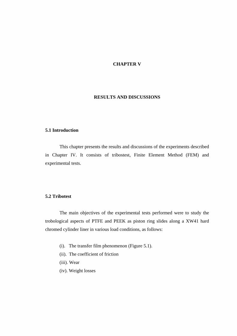
CHAPTER V
RESULTS AND DISCUSSIONS
5.1 Introduction
This chapter presents the results and discussions of the experiments described
in Chapter IV. It consists of tribostest, Finite Element Method (FEM) and
experimental tests.
5.2 Tribotest
The main objectives of the experimental tests performed were to study the
trobological aspects of PTFE and PEEK as piston ring slides along a XW41 hard
chromed cylinder liner in various load conditions, as follows:
(i). The transfer film phenomenon (Figure 5.1).
(ii). The coefficient of friction
(iii). Wear
(iv). Weight losses
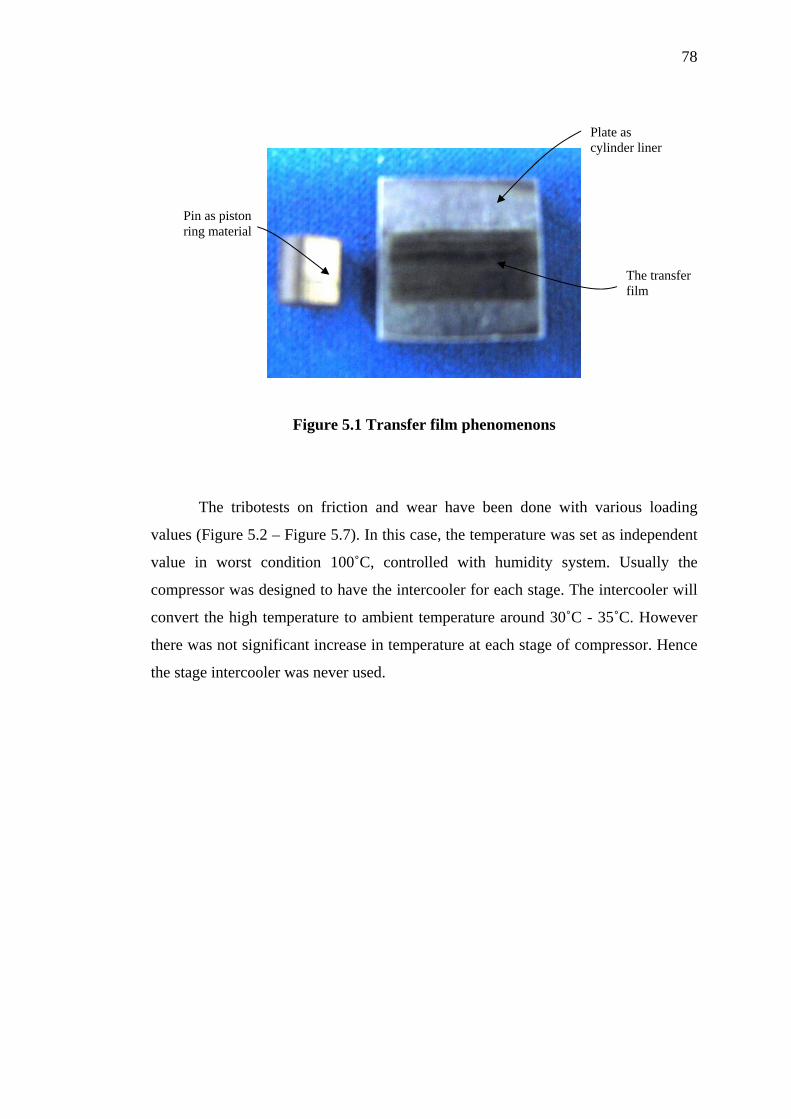
78
Plate as cylinder liner
Pin as piston ring material
The transfer film
Figure 5.1 Transfer film phenomenons
The tribotests on friction and wear have been done with various loading
values (Figure 5.2 – Figure 5.7). In this case, the temperature was set as independent
value in worst condition 100˚C, controlled with humidity system. Usually the
compressor was designed to have the intercooler for each stage. The intercooler will
convert the high temperature to ambient temperature around 30˚C - 35˚C. However
there was not significant increase in temperature at each stage of compressor. Hence
the stage intercooler was never used.
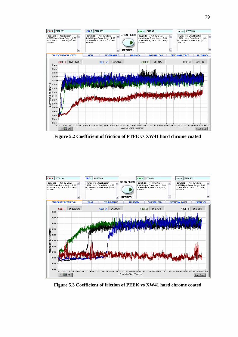
79
Figure 5.2 Coefficient of friction of PTFE vs XW41 hard chrome coated
Figure 5.3 Coefficient of friction of PEEK vs XW41 hard chrome coated
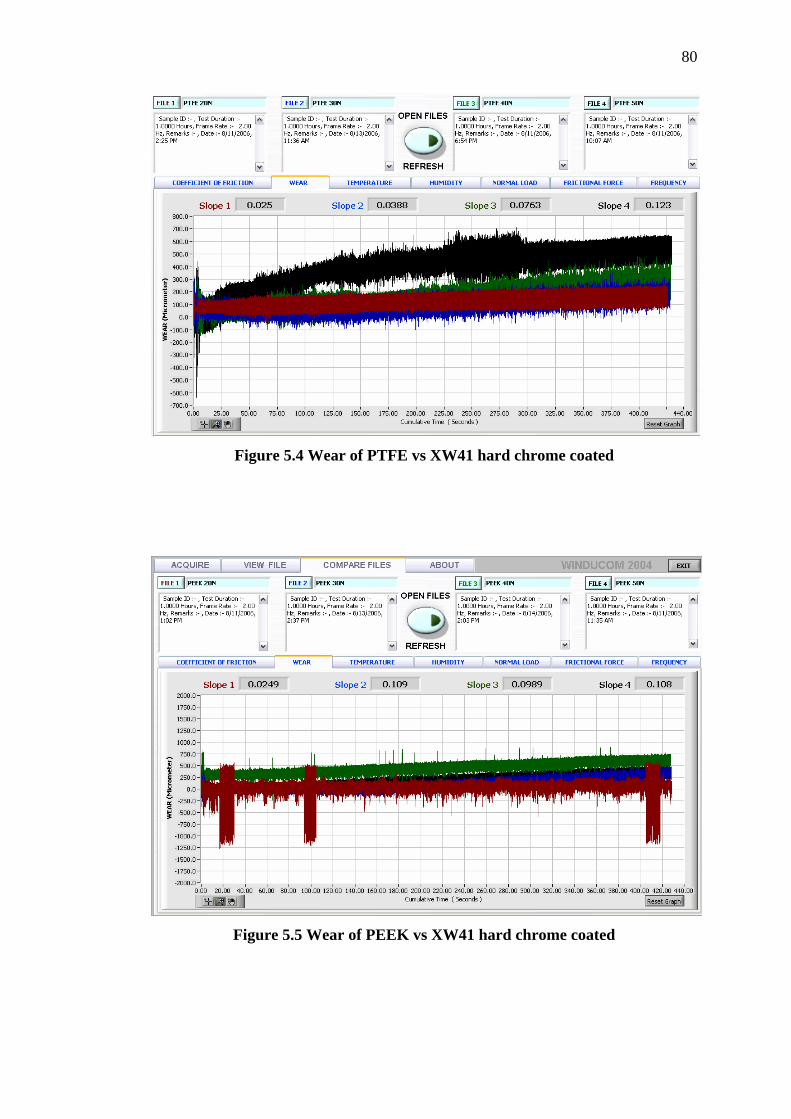
80
Figure 5.4 Wear of PTFE vs XW41 hard chrome coated
Figure 5.5 Wear of PEEK vs XW41 hard chrome coated
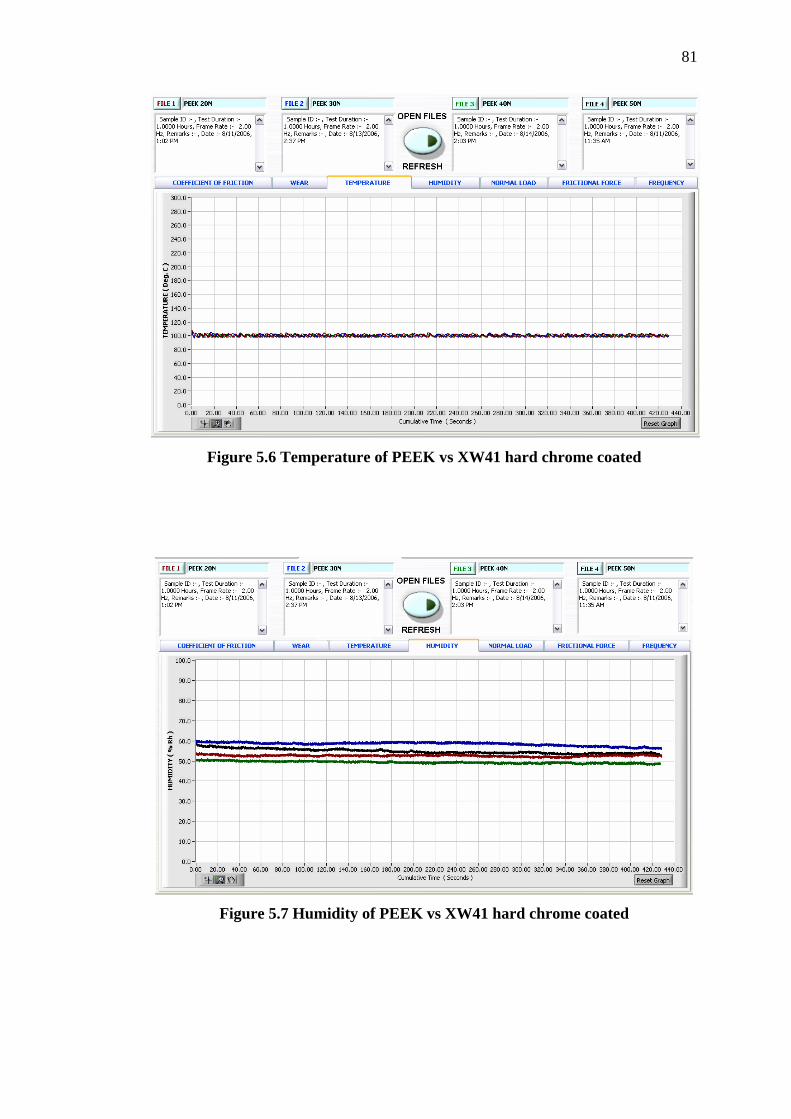
81
Figure 5.6 Temperature of PEEK vs XW41 hard chrome coated
Figure 5.7 Humidity of PEEK vs XW41 hard chrome coated

82
Table 5.1 Weight loss of PTFE material vs XW41 hard chrome coated: (gram)
Load Before After (N) Plate Pin Plate Pin
Weigh Loss of Pin(gr)
Weigh Loss of
Plate(gr) 20 6.9715 0.5277 6.9714 0.5245 0.0032 0.0001 30 7.259 0.5104 7.2588 0.4908 0.0096 0.0001 40 7.1765 0.5223 7.1763 0.5034 0.0189 0.0002 50 7.3704 0.5219 7.3703 0.4904 0.0215 0.0001
Table 5.2 Weight loss of PEEK material vs XW41 hard chrome coated: (gram)
Load Before After (N) Plate Pin Plate Pin
Weigh Loss of Pin(gr)
Weigh Loss of
Plate(gr) 20 6.9717 0.2055 6.9717 0.2148 0.0093 0 30 7.2407 0.211 7.2407 0.2015 0.0099 0 40 7.1796 0.2225 7.1795 0.2169 0.012 0.0001 50 6.9017 0.218 6.9017 0.2083 0.022 0
Weight Loss of Pin (PTFE)
0
0.005
0.01
0.015
0.02
0.025
20 30 40 50
Load (Newton)
Wei
ght L
oss
(Gra
m)
Figure 5.8 Weight loss of pin (PTFE)
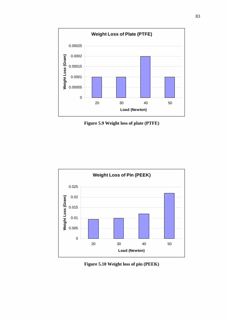
83
Weight Loss of Plate (PTFE)
0
0.00005
0.0001
0.00015
0.0002
0.00025
20 30 40 50
Load (Newton)
Wei
ght L
oss
(Gra
m)
Figure 5.9 Weight loss of plate (PTFE)
Weight Loss of Pin (PEEK)
0
0.005
0.01
0.015
0.02
0.025
20 30 40 50
Load (Newton)
Wei
ght L
oss
(Gra
m)
Figure 5.10 Weight loss of pin (PEEK)

84
Weight Loss of Plate (PEEK)
0
0.0001
0.0002
20 30 40 50
Load (Newton)
Wei
ght L
oss
(Gra
m)
Figure 5.11 Weight loss of plate (PEEK)
5.2.1 Summary and Discussions
The DUCOM Reciprocatory Friction and Wear Test Monitoring Machine,
was a very effective tool for evaluating the tribological performance of a piston ring-
cylinder liner. Presented in Figure 5.2 and 5.3 are the friction coefficient of PTFE
and PEEK as a function of the sliding time of 1 hour under 20N, 30N, 40N, 50N
applied loads. It can be seen that the friction coefficients significantly follow a trend
graph where friction coefficient increases with respect to time sliding and arrives at a
relatively stable value at steady state condition. For PTFE, under 20N applied load
the friction coefficient have minimum value µ = 0.12. Under 30N, 40N, 50N applied
load, the friction coefficient showed a stable value ranging from µ = 0.20 to µ = 0.22.
This condition does not exceed much the steady state value of friction. These result
can be obtained as value of friction coefficient for PTFE sliding against XW41 hard
chromed. The same trend as showed for PEEK material where the steady state
friction coefficient were ranging from µ = 0.29 to µ = 0.37.

85
Variations of wear with sliding under load as a function of time are shown in
Figure 5.4 and Figure 5.5 respectively. For PTFE material, the differences of wear
under 20N and 50N load become more significant while time increased. However,
for PTFE and PEEK material, the wear rate shown the same trend and close value of
wear. In maximum load 50N, the wear of PTFE given the high wear rate W = 0.12
µm comparison with PEEK W = 0.10 µm. However the wear for 20N, 30N, 40N for
both materials are shown to be stable and in a steady state condition ranging from W
= 0.02 µm to W = 0.10 µm.
Overall, the results of weight loss of both materials are shown in Figure 5.8
and Figure 5.9 which show an agreement respectively with the established trends,
which showed that mass loss increased with the increasing of the normal load.
Significantly, higher mass losses of pin were under higher load 50 N around 0.02
grams. On the other hand, the cylinder liner specimen showed a negligible mass loss
under various load (Figure 5.10 and 5.11).
5.3 Design and Modeling Using Finite Element Analysis (FEA)
Static analyses were done on the critical parts which are the piston, cylinder
liner, and piston rings. These parameters are as an input data from analysis in section
above are used to calculate the load acting on each part of Piston Ring Assembly
(PRA). In the analysis, the gas compression force during TDC for each stage was
used as the loading input. Through this analysis, stresses on the Piston Ring
Assembly (PRA) parts and its strength can be assessed.

86
Table 5.3 Results for stress analysis on the pistons:
Stage Yield strength (MPa)
Maximum Von mises stress (MPa)
Maximum displacement (m)
Safety factor
1 215 19.47 2.42 x 10⁻⁶ 11 2 215 13.50 1.81 x 10⁻⁶ 15 3 215 12.13 1.61 x 10⁻⁶ 17 4 215 34.64 4.41 x 10⁻⁶ 6
Gas pressure on the piston
Fixed surfaces
Figure 5.12 Loads and boundary conditions of the piston (first stage)
Highest stress
Figure 5.13 Von Mises stress of the piston (first stage)
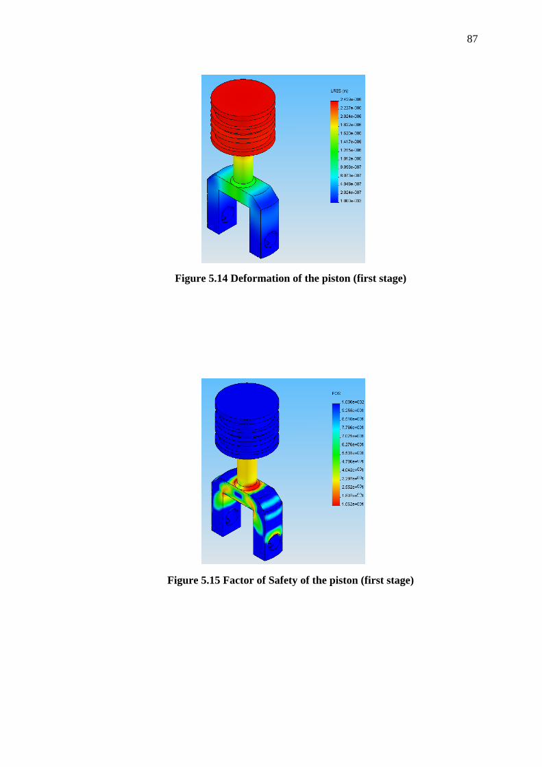
87
Figure 5.14 Deformation of the piston (first stage)
Figure 5.15 Factor of Safety of the piston (first stage)
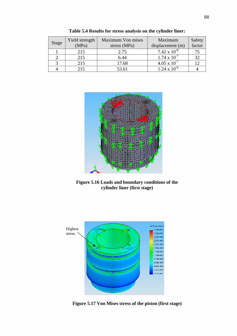
88
Table 5.4 Results for stress analysis on the cylinder liner:
Stage Yield strength (MPa)
Maximum Von mises stress (MPa)
Maximum displacement (m)
Safety factor
1 215 2.75 7.42 x 10⁻⁸ 75 2 215 6.44 1.74 x 10⁻⁷ 32 3 215 17.68 4.05 x 10⁻⁷ 12 4 215 53.61 1.24 x 10⁻⁶ 4
Figure 5.16 Loads and boundary conditions of the cylinder liner (first stage)
Highest stress
Figure 5.17 Von Mises stress of the piston (first stage)

89
Figure 5.18 Deformation of the cylinder liner (first stage)
Figure 5.19 Factor of Safety of the cylinder liner (first stage)

90
Table 5.5 Results for stress analysis on the piston ring assembly (PTFE):
Stage Yield strength (MPa)
Maximum Von mises stress (MPa)
Maximum displacement (m)
Safety factor
1 28 2.55 1.45 x 10⁻⁷ 11 2 28 4.02 2.19 x 10⁻⁶ 7 3 28 8.23 4.87 x 10⁻⁶ 3 4 28 15.56 5.25 x 10⁻⁶ 1.8
Table 5.6 Results for stress analysis on the piston ring assembly (PEEK):
Stage Yield strength (MPa)
Maximum Von mises stress (MPa)
Maximum displacement (m)
Safety factor
1 110 3.95 2.23 x 10⁻⁷ 28 2 110 6.48 3.58 x 10⁻⁶ 17 3 110 13.76 6.54 x 10⁻⁶ 8 4 110 36.68 7.86 x 10⁻⁶ 3
Figure 5.20 Loads and boundary conditions of the piston ring (PTFE)
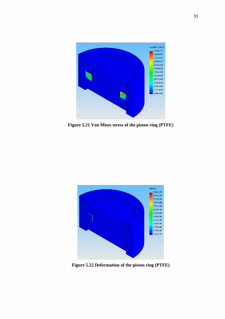
91
Figure 5.21 Von Mises stress of the piston ring (PTFE)
Figure 5.22 Deformation of the piston ring (PTFE)
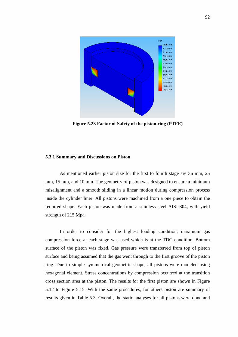
92
Figure 5.23 Factor of Safety of the piston ring (PTFE)
5.3.1 Summary and Discussions on Piston
As mentioned earlier piston size for the first to fourth stage are 36 mm, 25
mm, 15 mm, and 10 mm. The geometry of piston was designed to ensure a minimum
misalignment and a smooth sliding in a linear motion during compression process
inside the cylinder liner. All pistons were machined from a one piece to obtain the
required shape. Each piston was made from a stainless steel AISI 304, with yield
strength of 215 Mpa.
In order to consider for the highest loading condition, maximum gas
compression force at each stage was used which is at the TDC condition. Bottom
surface of the piston was fixed. Gas pressure were transferred from top of piston
surface and being assumed that the gas went through to the first groove of the piston
ring. Due to simple symmetrical geometric shape, all pistons were modeled using
hexagonal element. Stress concentrations by compression occurred at the transition
cross section area at the piston. The results for the first piston are shown in Figure
5.12 to Figure 5.15. With the same procedures, for others piston are summary of
results given in Table 5.3. Overall, the static analyses for all pistons were done and

93
highest stress concentrations were seen at the neck between the piston rod and
coupler.
5.3.2 Summary and Discussions on Cylinder Liner
Analysis the first stage cylinder liner, stress concentrations occurred at the
location of the contact interaction between the rigid surfaces and the cylinder bore.
The outside diameter was fixed at its reference point. The maximum gas compression
force during Top Dead Centre (TDC) condition at each stage was inserted as a point
load at the bore of cylinder liner. At the top of cylinder liner, are the two bolt holes
meant for valve assembly. This region has high stress concentrations and
displacement but not effected to the cylinder liner as a part of compression process.
The same patent of stress concentration and displacement also occurred for the
analysis at the other stages. The results of the analysis for the other stages are given
in Table 5.4 and the FEA results for the first cylinder liner are shown in Figure 5.16
to Figure 5.19.
5.3.3 Summary and Discussions on Piston Rings
For piston ring analysis, the static analyses were done for both material,
PTFE and PEEK. Thus in this analysis, the multi-body contact analysis method (in 3-
Dimension) was used to obtain the boundary condition location where the piston ring
has interacted with piston and cylinder liner. In this case, the top piston ring is
critical part and worst condition because the gas compression was applied first at the
top of piston ring which is installed in the piston groove. Pressure loading from the
gas compression process was applied on the piston top surface. In actual condition,
the gas pressure was applied to the ring through the groove of the piston. At the TDC
and under ideal piston ring condition no gas leakage is assumed through the second
ring.
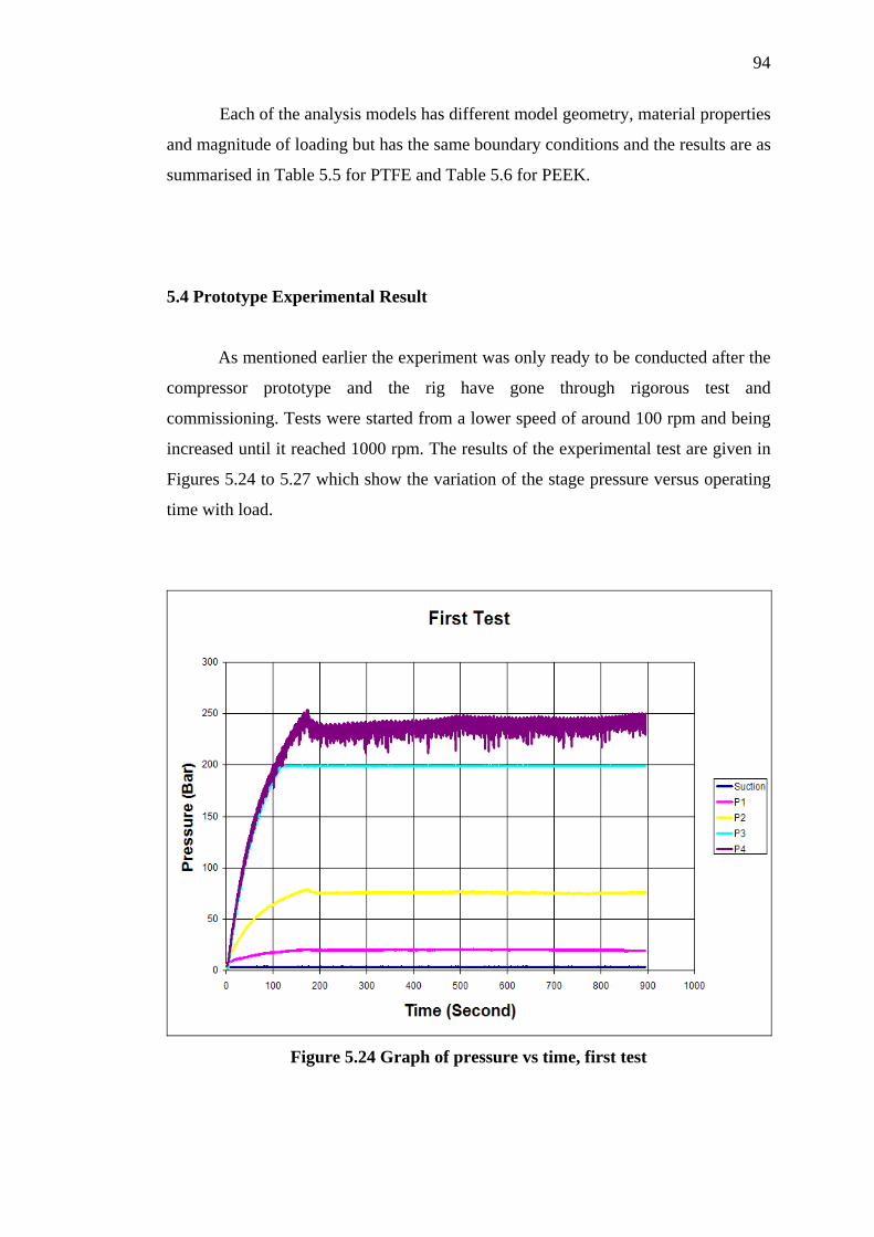
94
Each of the analysis models has different model geometry, material properties
and magnitude of loading but has the same boundary conditions and the results are as
summarised in Table 5.5 for PTFE and Table 5.6 for PEEK.
5.4 Prototype Experimental Result
As mentioned earlier the experiment was only ready to be conducted after the
compressor prototype and the rig have gone through rigorous test and
commissioning. Tests were started from a lower speed of around 100 rpm and being
increased until it reached 1000 rpm. The results of the experimental test are given in
Figures 5.24 to 5.27 which show the variation of the stage pressure versus operating
time with load.
Figure 5.24 Graph of pressure vs time, first test

95
Figure 5.25 Graph of pressure vs time, second test
Figure 5.26 Graph of pressure vs time, third test
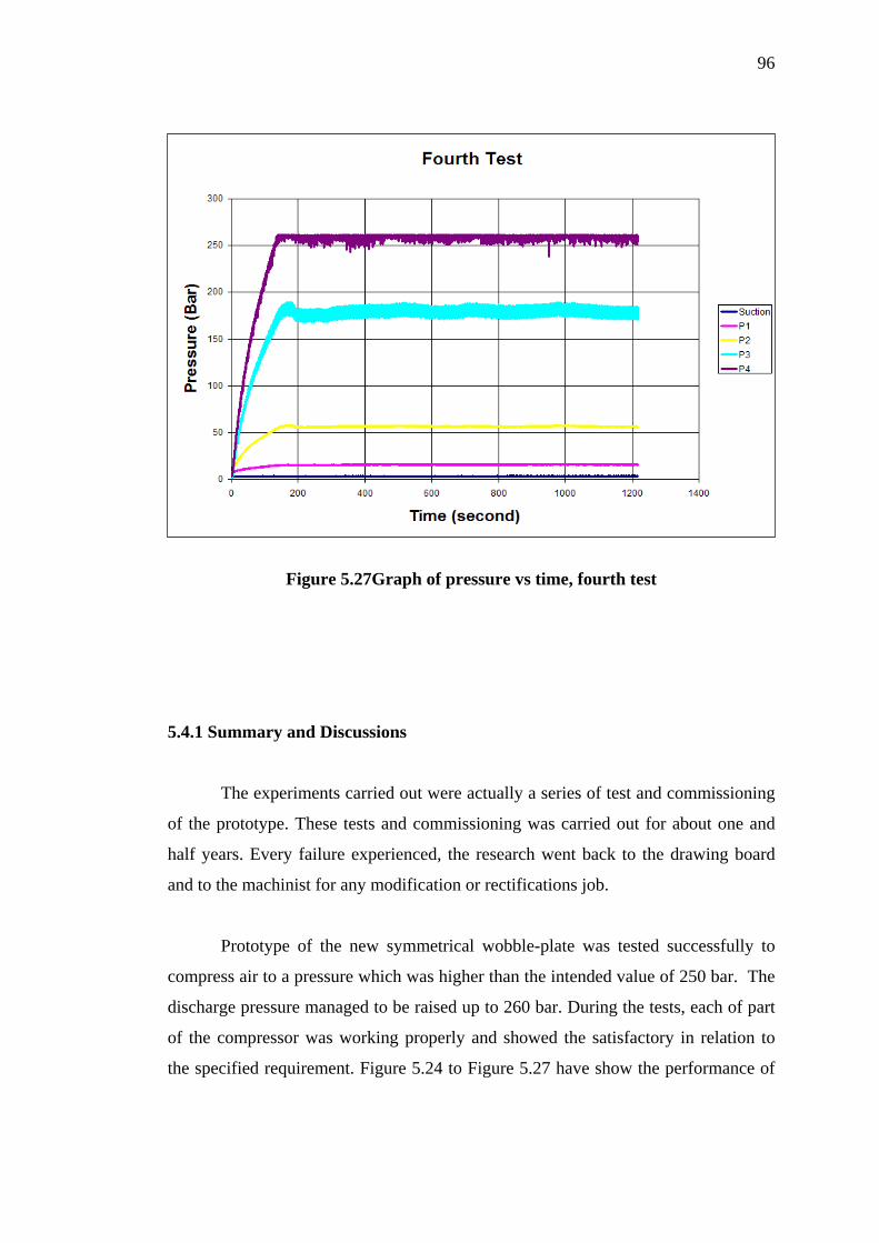
96
Figure 5.27Graph of pressure vs time, fourth test
5.4.1 Summary and Discussions
The experiments carried out were actually a series of test and commissioning
of the prototype. These tests and commissioning was carried out for about one and
half years. Every failure experienced, the research went back to the drawing board
and to the machinist for any modification or rectifications job.
Prototype of the new symmetrical wobble-plate was tested successfully to
compress air to a pressure which was higher than the intended value of 250 bar. The
discharge pressure managed to be raised up to 260 bar. During the tests, each of part
of the compressor was working properly and showed the satisfactory in relation to
the specified requirement. Figure 5.24 to Figure 5.27 have show the performance of
97
the compressor (or piston ring assembly) as the pressure of after each stage is raised
gradually until steady state condition was arrived.
Figure 5.24 and Figure 5.25 show that the compressor has produced the
pressure around 230-240 bar. The maximum pressure obtained for first test was only
240 bar at the end of test, but the time taken was about 900 second which was too
long. The compressor was stopped to investigate condition of all mechanical parts
and to look at any damaging effect of testing inside the compressor casing. When
every moving parts was found to be in good condition, the second test was carried
out and produced the high pressure of 240 bar at a relatively longer 1700 second to
reach steady state. This result can be seen in Figures 5.25. More investigation was
needed to find this problem of long transient time. After this second test, it was found
that there was a technical problem at the pressure relief valve which was not properly
calibrated. Although set at 250 bar the relief valve opened at 240 bar.
After the setting of pressure relief valve problem was overcome, a fourth test
was conducted. The results are given in Figure 5.26. During this test, the maximum
pressure was surprisingly higher and reached a steady value of around 260 bar. This
test was continued with a longer time and the piston ring assembly seemed to be able
to function at steady state at 260 bar of final discharge pressure, as shown Figure
5.27. Through these testings, it could be concluded that the main objective of the
study was finally achieved, which is to prove that the material selection, design,
analysis of piston ring assembly is able to compress air up to 250 bar, while at the
same time the set specifications of the new symmetrical wobble-plate compressor are
met.
CHAPTER VI
CONCLUSIONS AND RECOMMENDATIONS
6.1 Conclusions
In this research, Piston Ring Assembly (PRA) for a new symmetrical wobble-
plate compressor for Home Refueling Appliance (HRA) was designed, developed,
and successfully tested. The significant outcomes of this study can be summarised as
follows:
1. Piston Ring Assembly (PRA) is a critical component which contributes to the
majority of frictional losses in a reciprocating compressor where the selection
of material for Piston Ring Assembly (PRA) is very important to meet the
specified compressor performance.
2. PTFE and PEEK materials of piston rings are suitable for this oil-free
lubrication for a new symmetrical wobble-plate compressor.
3. Coefficients of friction of PTFE and PEEK sliding against XW41 hard
chromed have values ranging from µ = 0.20 to µ = 0.22 and µ = 0.29 to µ =
0.37 respectively.
4. Wear rate of PTFE was found to be between 0.02µm/hr to 0.12µm/hr and that
of PEEK was between 0.02µm/hr to 0.10µm/hr.
99
5. The new symmetrical wobble-plate reciprocating compressor prototype and
its piston ring design, material and assembly have been tested successfully to
compress air to extremely high pressure of 260 bar.
6.2 Recommendations for Future Research
This research has carried out work on the development of Piston Ring
Assembly (PRA) for a new symmetrical wobble plate compressor. However there are
still several aspects could be done or continued to further develop the new
compressor in term of performance:
1. Perform endurance test on the Piston Ring Assembly (PRA) to predict the
operating life.
2. In order to improve performance of the piston ring, test on the polymer as a
self lubricated material should be conducted with other fillers combinations.
3. The tribotest on friction and wear should be tested under various tribological
environments that practically influence the performance of Piston Ring
Assembly (PRA) e.g. speed, temperature, surface roughness, time or distance.

REFERENCES
Affenzeller, J. and Gläser, H. (1996). Bearings and Lubrication of Internal
Combustion Engines In German. Vienna, Austria, Springer-Verlag. 397 p.
ISBN 3-211-82577-0.
Ahmad, Z. A. (2006). Structural Design and Analysis of A New Symmetrical
Multi-Stage Wobble-Plate Compressor. MEng, Thesis Universiti Teknologi
Malaysia.
American Petroleum Institute (2005). API 618: Reciprocating Compressors for
Petroleum, Chemical, and Gas Industry Services. America: American
Petroleum Institute.
Baumann, H. (1994). Design Features of a Small Oil-Free, Reciprocating, High
Pressure Compressor. Proceedings International Compressor Conference
Purdue University: 381-385.
Baumann, H. and Conzett, M. (2002). Small Oil Free Piston Type Compressor for
CO2. Proceedings International Compressor Conference Purdue University.
Blau, P. J. (1999). Fifty Years of Research on the Wear of Metals. Elsevier
Science, Tribology International Volume 30 Number 5.
Bloch, H and Hoefner, J. (1996). Reciprocating Compressors:
Operation and Maintenance. Butterworth-Heinemann.
101
Bottomley, J. W. (1994). Application of New Sealing Component Materials To
Reciprocating Compressors. IMechE Journal, C477/013/1994.
Chui, B, K. (2001). Computational Analysis of Piston Ring Wear and Oil
Consumption for an Internal Combustion Engine. MsC Thesis. Michigan
State University,
Chlumsky, V. (1965). Reciprocating and rotary compressor. SLTN Publisher of
Technical Literature. Prague, Czechoslovakia.
Dunaevsky, V. (2001). The Effect of Contact Pressure on Piston Ring Twist.
SAE Paper No. 2001-01-2720.
Dunaevsky, V. (1999). Analysis of Elastic Distorsions of a Piston Ring in the
Reciprocating Air Brake Compressor Due to the Installation Stresses. SAE
Paper No. 1999-01-3770.
Dwivedi, S. N. (1990). Design Consideration for High Pressure Reciprocating
Compressor for Refinery services. International Compressor Engineering
Conference at Purdue pp 273-281.
Gupta, P. (2001). On a Multi-Process Wear Model. Lubrication Engineering.
57(2001)4, pp. 19–24.
Hanlon, P.C. (2001).Compressor Handbook. New York: McGraw-Hill.
Haubner, F. G. (2001). Simulation of the Piston Ring Dynamis. SAE Paper No.
2001-01-3368.
Hariu, N., Nakayama, K., Hill, W.R. (1991). Dynamic Analysis Of A Variable
Capacity Compressor For A Vehicle Air-conditioning Using Finite Element
Methods. SAE Paper, No. 910213.
102
Ishi, N., Abe, Y., Taguchi, T., Maruyama, T. and Kitamura, T. (1990). Dynamic
Behaviour of Variable capacity Wobble-plate Compressor for Automotive Air
Conditioners. Proc. Int. Compressor Conf., Purdue University: 345-353.
Kauzlarich, J. J. and Williams, J. A. (2001). Archard Wear and Component
Geometry. Proceedings of the Institution of Mechanical Engineers Part J.
Journal of Engineering Tribology, 215-4, pp. 387–403.
Maczek, K. and Wolek, W. (1994). Confinement and Advoidance of Lubricants in
Reciprocating Compressors. Proceedings International Compressor
Conference Purdue University.
Mid-Michigan Research. (1998). CASE Theoretical Manual. Mid-Michigan
Research.
Musa, M.N. (2005). Wobble Plate Compressor. (PI 2005 5456).
Nishikawa, H. and Nishikawa, T. (1998). Development of the Non-Lubricated Four-
Stage Compressor Compressing Up To 24.25MPa. Proceedings International
Compressor Conference Purdue University: 183-188.
Nishikawa, T., Nishikawa, H., Obokata, T. and Ishima, T. (2000). A Study for
Improvement on High Pressure Multi-stage Reciprocating Compressor.
Proceedings International Compressor Conference Purdue University: 105-
112.
Ouwerkerk, C. and Theeuwes, G. (1981). Leakage and Friction of Different Dry-
Running Piston Ring. 9th International Conference on Fluid Sealing. Paper
F1.
Poole, E. J. (1978). Development Since 1950 of Standard Range Industrial Air
Compressor. IMechE C16/78.
103
Priest, M. and Taylor, C. M. (2000). Automobile Engine Tribology - Approaching the
Surface. Wear, 241-2, pp. 193–203.
Radcliffe, C. (2005). Sealing Material Developments for Reciprocating Gas
Compressor. Sealing Technology Journal.
Riegger, O.K. (1990). Design Criteria and Performance of an Advance
Reciprocating Compressor. Proceedings International Compressor
Conference Purdue University: 61-68.
Sherrington, I. and Mercer, S. (2000). The Use of Topography-Based Parameters for
The Assessment and Prediction of Surface Wear. Tribotest 7, pp. 3–11.
Shivakant and Krishna. (2001). Mechanics and Stress Analysis of Piston Ring In
Multibody Single Cylinder Internal Combustion Engine-FE Analysis.
Proceedings International Compressor Conference Purdue University.
Shuster, M., Mahler, F., and Crysler, D. (1999). Metallurgical and Metrological
Examinations of The Cylinder Liner - Piston Ring Surfaces After Heavy Duty
Diesel Engine Testing. STLE Tribology Transactions, 42, pp. 116–125.
Smith, E. H. (1994). Mechanical Engineer’s Reference Books. Twelfth Edition
Butterworth-Heinemann.
Society of Automotive Engineers (SAE). (1969). Metallic Seal Rings for High
Temperature Reciprocating Hydraulic Service. SAE-AIR 1077.
Syahrom, A. (2006). Design and Development of Multi-Stage
Symmetrical Wobble-Plate Compressor. MEng. Thesis. Universiti Teknologi
Malaysia.
Tian, C.Q., Dou, C.P., Yang, X.J., Li, X.T. (2004). A mathematical model of
Variable displacement wobble-plate compressor for automotive air
conditioning system. Applied Thermal Engineering Vol. 24: 2467-2486.

104
Todsen, U and Kruse, H. (1982). Hydrodynamic Optimisation of The Tribological
System Piston-Ring-Liner. Proceedings International Compressor Conference
Purdue University.
Tojo, K., Takao, K., Ito, M. and Hayase, I. (1990). Dynamic Behaviour of variable
capacity compressor for automotive air conditioners. SAE Paper, No.
900084.
Wilson, R. S. (1990). Development in Piston and Rod Sealing Material for Oil-free
Gas Compressor. IMech E. Fluid Machinery Congress The Hague.
Wrede, F. (1978). Comparison of Mathematical and Experimental Simulation of
Lubrication Condition In the System of Piston, Piston Ring and Liner.
Proceedings International Compressor Conference Purdue University.
Yong, L. (1986). Prediction for The Sealing Characteristics of Piston Rings of a
Reciprocating Compressor. Proceedings International Compressor
Conference Purdue University.

105
APPENDIX A
Piston Groove Dimension of Piston Ring
(According to ISO 7425/1)
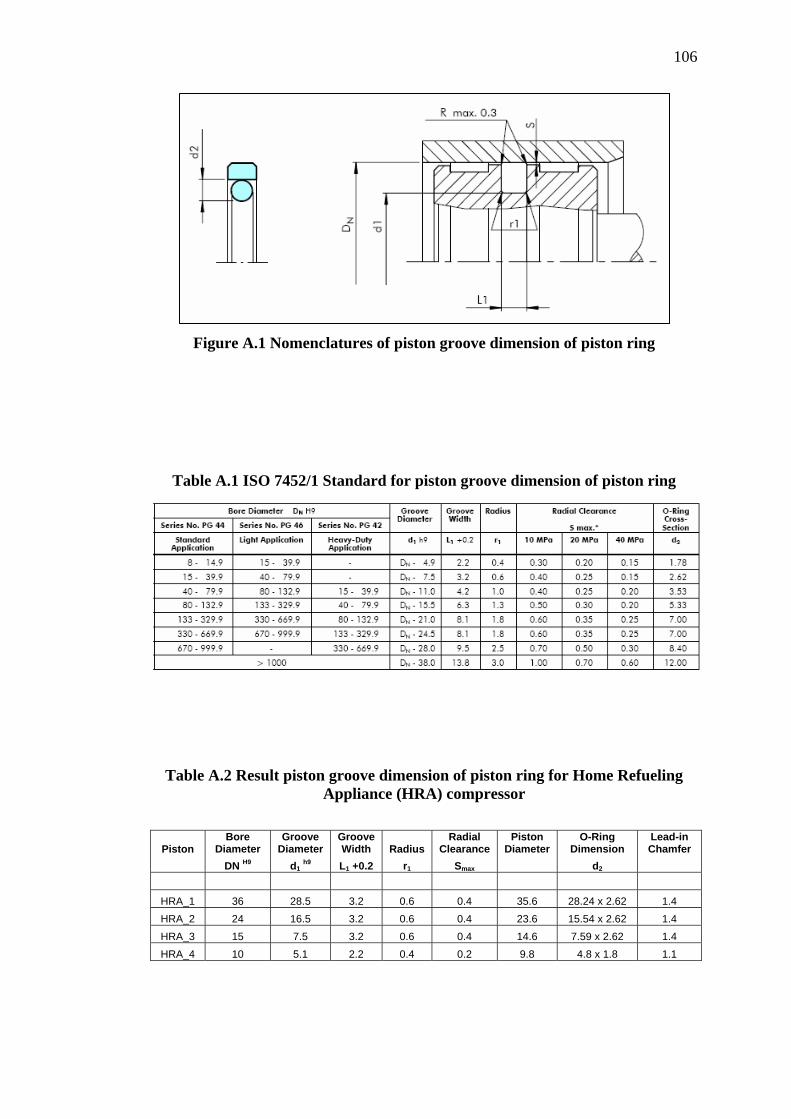
106
Figure A.1 Nomenclatures of piston groove dimension of piston ring
Table A.1 ISO 7452/1 Standard for piston groove dimension of piston ring
Table A.2 Result piston groove dimension of piston ring for Home Refueling Appliance (HRA) compressor
Piston Bore
Diameter Groove
Diameter Groove Width Radius
Radial Clearance
Piston Diameter
O-Ring Dimension
Lead-in Chamfer
DN H9 d1 h9 L1 +0.2 r1 Smax d2
HRA_1 36 28.5 3.2 0.6 0.4 35.6 28.24 x 2.62 1.4 HRA_2 24 16.5 3.2 0.6 0.4 23.6 15.54 x 2.62 1.4 HRA_3 15 7.5 3.2 0.6 0.4 14.6 7.59 x 2.62 1.4 HRA_4 10 5.1 2.2 0.4 0.2 9.8 4.8 x 1.8 1.1

107
APPENDIX B
Piston Groove Dimension of Rider/ Guide Ring
(According to ISO 7425/1)

108
Figure B.1 Nomenclatures of piston groove dimension of rider/ guide ring
Table B.1 ISO 7452/1 Standard for piston groove dimension of rider/guide ring
Table B.2 Result piston groove dimension of rider/ guide ring for Home Refueling Appliance (HRA) compressor
Piston Bore
Diameter Groove
Diameter Groove Width Thickness Radius
Radial Clearance
Ring Gap
DN H9 d2 h8 L2 +0.2 W rmax S1 Z
HRA_1 36 31 5.6 2.5 0.2 0.4 2
HRA_2 24 19 5.6 2.5 0.2 0.4 2
HRA_3 15 11.9 4 1.55 0.2 0.4 2
HRA_4 10 6.9 4 1.55 0.2 0.2 2
109
APPENDIX C Material properties of Piston Ring Assembly (PRA):
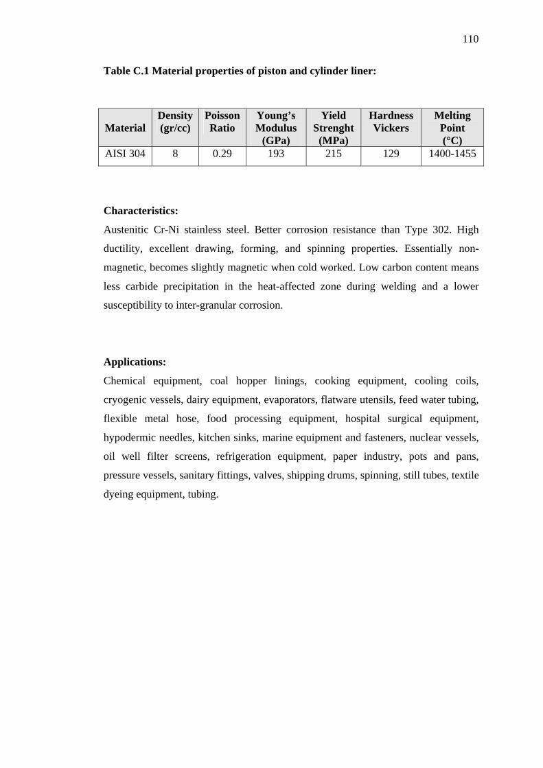
110
Table C.1 Material properties of piston and cylinder liner:
Material
Density (gr/cc)
PoissonRatio
Young’s Modulus
(GPa)
Yield Strenght (MPa)
Hardness Vickers
Melting Point (°C)
AISI 304 8 0.29 193 215 129 1400-1455
Characteristics:
Austenitic Cr-Ni stainless steel. Better corrosion resistance than Type 302. High
ductility, excellent drawing, forming, and spinning properties. Essentially non-
magnetic, becomes slightly magnetic when cold worked. Low carbon content means
less carbide precipitation in the heat-affected zone during welding and a lower
susceptibility to inter-granular corrosion.
Applications:
Chemical equipment, coal hopper linings, cooking equipment, cooling coils,
cryogenic vessels, dairy equipment, evaporators, flatware utensils, feed water tubing,
flexible metal hose, food processing equipment, hospital surgical equipment,
hypodermic needles, kitchen sinks, marine equipment and fasteners, nuclear vessels,
oil well filter screens, refrigeration equipment, paper industry, pots and pans,
pressure vessels, sanitary fittings, valves, shipping drums, spinning, still tubes, textile
dyeing equipment, tubing.

111
Table C.2 Material properties of piston ring (PTFE):
Material
Density (gr/cc)
PoissonRatio
Young’s Modulus
(GPa)
Yield Strenght(MPa)
Hardness Vickers
Melting Point (°C)
PTFE
40% Bz
3.13 0.33 0.46 28 67 260
Characteristics:
This material exhibits a unique combination of heat resistance and low friction
together with outstanding chemical and good electrical properties. Continuous use
temperatures range -204°C to +260°C, no moisture absorption, high arc resistance,
and is self lubricating with a low coefficient of friction. Compounds of bronze and
Teflon improve creep strength, thermal conductivity and wear resistance of moldings
as well as low friction.
Applications:
Useful in applications which undergo high mechanical loads or high-speed rubbing
contacts where the bronze filler supplies the strength and conductivity to carry away
excess, unwanted heat, e.g. piston ring, rider ring, journal bearing, valve plate, etc.

112
Table C.3 Material properties of piston ring (PEEK):
Material
Density (gr/cc)
PoissonRatio
Young’s Modulus
(GPa)
Yield Strenght(MPa)
Hardness Vickers
Melting Point (°C)
PEEK 1.44 0.4 8.3 110 130 344
Characteristics:
PEEK exhibits excellent resistance to a wide range of organic and inorganic
chemicals. Polyethetetherketone ( PEEK ) is a high performance thermoplastic with
the characteristics common to this group - strong, stiff, hard, high temperature
resistance, good chemical resistance and inherently low flammability and smoke
emission. PEEK is pale amber in color and usually semi-crystalline and opaque,
except thin films are usually amorphous and transparent. It also has very good
resistance to wear, dynamic fatigue and radiation, but it is difficult to process and
very expensive.
Applications:
Applications include flexible printed circuit boards (film), piston ring, rider ring,
journal bearing, valve plate, monofilaments, injection molding engineering
components and items used in aerospace and radiation environments. etc.
113
APPENDIX D
Patent Filing No: PI 2005 5056
(Wobble Plate Compressor)
114

115

116
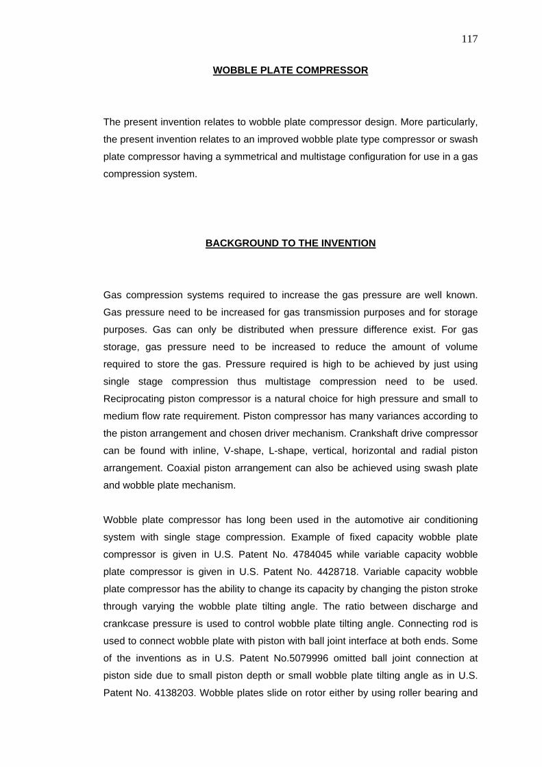
117
WOBBLE PLATE COMPRESSOR
The present invention relates to wobble plate compressor design. More particularly,
the present invention relates to an improved wobble plate type compressor or swash
plate compressor having a symmetrical and multistage configuration for use in a gas
compression system.
BACKGROUND TO THE INVENTION
Gas compression systems required to increase the gas pressure are well known.
Gas pressure need to be increased for gas transmission purposes and for storage
purposes. Gas can only be distributed when pressure difference exist. For gas
storage, gas pressure need to be increased to reduce the amount of volume
required to store the gas. Pressure required is high to be achieved by just using
single stage compression thus multistage compression need to be used.
Reciprocating piston compressor is a natural choice for high pressure and small to
medium flow rate requirement. Piston compressor has many variances according to
the piston arrangement and chosen driver mechanism. Crankshaft drive compressor
can be found with inline, V-shape, L-shape, vertical, horizontal and radial piston
arrangement. Coaxial piston arrangement can also be achieved using swash plate
and wobble plate mechanism.
Wobble plate compressor has long been used in the automotive air conditioning
system with single stage compression. Example of fixed capacity wobble plate
compressor is given in U.S. Patent No. 4784045 while variable capacity wobble
plate compressor is given in U.S. Patent No. 4428718. Variable capacity wobble
plate compressor has the ability to change its capacity by changing the piston stroke
through varying the wobble plate tilting angle. The ratio between discharge and
crankcase pressure is used to control wobble plate tilting angle. Connecting rod is
used to connect wobble plate with piston with ball joint interface at both ends. Some
of the inventions as in U.S. Patent No.5079996 omitted ball joint connection at
piston side due to small piston depth or small wobble plate tilting angle as in U.S.
Patent No. 4138203. Wobble plates slide on rotor either by using roller bearing and

118
thrust bearing, thrust bearing and spherical bearing or roller bearing only as found in
U.S. Patent No. 4867649, 4869651 and 4138203 respectively. Wobble plate is
prevented from rotating with rotor using anti rotation mechanism which is either
thrust rider and slider plate (U.S. Patent No. 3552886), ball and slider plate (U.S.
Patent No. 4105370), ball and guide rod mechanism (U.S. Patent No. 5094590),
Rzeppa mechanism (U.S. Patent No. 5079996) and bevel gear (U.S. Patent No.
4869651). Slanted or fully supported drive shaft at both ends has been used in all
previous invention. Rotor shapes for fixed capacity wobble plate compressor tend to
be simpler as found in U.S. Patent No. 4869651 whereby for variable capacity
wobble plate compressor, some arrangement is needed to change wobble plate
tilting angle with the typical design is as found in U.S. Patent No. 4428718. Many
improvements or design variation has been made on this mechanism alone.
Housing design is normally split into two and three piece parts with cylinder block
imbedded into the housing. End plate is used to house valve plate and lubrication
pump.
SUMMARY OF THE INVENTION
Accordingly, it is an object of the current invention to provide a wobble plate type
compressor aligned in symmetrical configuration, which results in significant
reduction of vibration of the compressor. The pistons, cylinder block and wobble
plate which mirror each other at the centre of drive shaft reduces if not eliminates
the horizontal force caused by gas reaction forces acting on the pistons.
Another object of the current invention is the introduction of multistage configuration
that will allow higher gas compression than normally attained in single stage wobble
plate compressors used in automotive refrigeration.
A further object of the current invention is to provide a wobble plate of the character
described which is particularly designed to compress gas without oil contamination.
This feature eliminates the inevitable blow-by of oil vapor passing into the gas being
compressed, as the present feature is free from lubricating requirements on the part
of the operator between periodic maintenance.
Yet another object of the current invention is to provide a compressor of the
characters above which will involve a fewer number of parts with reduced machining

119
requirements, and which may be easily and rapidly assembled to provide a unit at
minimum cost.
Yet another object of the present invention is to provide a wobble plate compressor
of the characters described which is composed of durable parts affording easy
disassembly when required for maintenance and affording long, useful life.
Still another object of the present invention is to provide a structure of the character
described which may be scaled up or down to readily provide units of different sizes
and capacities and also be adopted to swash plate type compressors.
BRIEF DESCRIPTION OF THE DRAWINGS
The invention will now be described in greater detail, by way of an example, with
reference to the accompanying drawings, in which:
Figure 1 is the isometric view of the compressor illustrating the housing, left and
right end plate and acrylic cover;
Figure 2 is a see through drawing illustrating the assemblies of the internal
component in the compressor;
Figure 3 is a section view showing parts of wobble plate and anti-rotation
mechanism;
Figure 4 is the isometric view of piston assemblies illustrating different size and
shapes of pistons and couplers;
Figure 5 is a cross section view of wobble plate assemblies illustrating the
components involved;
Figure 6 illustrates the arrangement of cylinder block at the end plate, shown here
with possible fittings arrangement at the suction and discharge port at each cylinder
block;
Figure 7 is a cross section view of piston assemblies illustrating the components
involved;
120
Figure 8 is a cross section view of cylinder block illustrating arrangement of liner,
valve cover, suction valve plate and discharge valve plate; and
Figure 9 is cross section view of cylinder block illustrating the suction port and
discharge port.
DETAILED DESCRIPTION OF THE DRAWINGS
Referring to Figure 1 through Figure 9, wherein like numerals indicate like
corresponding parts throughout the nine views, a symmetrical multistage wobble
plate compressor is generally shown.
The compressor has a housing, which includes crank case 1, left end plate 2, right
end plate 3 and acrylic cover 4. Left end plate 2 and right end plate 3 are clamped to
crank case 1 using bolts.
The compressor of the present invention comprises of two sets of pistons in cylinder
blocks 5, wobble plate 6, rotor 7 that mirror each other as shown in Figure 2. Drive
shaft 8 is stepped at both ends to locate and fix the bearing at the end plate 2, 3 at
both ends. Drive shaft 8 and rotor 7 are fixed together using pin. Rotor 7 and wobble
plate 6 is connected together through deep groove bearing 9. Wobble plate 6 have
slots for wobble plate pins 10, slot for anti-rotation ball 11 and flange at the front
face around the periphery of bearing slot at its centre. Rotor 7 is provided with a slot
for pin and flange at the back face.
Bearing 9 is tight fitted to both rotor 7 and wobble plate 6. External c-clip is used to
secure rotor 7 with bearing 9 while internal c-clip is used to secure wobble plate 6 with bearing 9. This will prevent wobble plate 6 or bearing 9 from sliding to the front
in case of tight fit failure. Flange at the front face of wobble plate 6 will press against
the front face of bearing outer race 12 whereas flange at the back of rotor 7 will
press against the back face of bearing inner race 13. This will ensure bearing 9 or
wobble plate 6 from sliding to the back in case of tight fit failure.
121
Rotation of drive shaft 8 with rotor 7 will induce wobbling motion in the wobble plate
6 through the bearing 9 interface. Wobble plate 6 is prevented from rotating with
rotor 7 by the anti rotation mechanism which consist of a guide rod 14 and hollow
spherical ball 11 that slide horizontally on the guide rod 14 and up and down in the
slot for anti-rotation ball at wobble plate 6. Wobble plate 6 wobbling motion will be
transferred into piston 15 reciprocating motion through connecting rod 16. End joint
connection is used as the interface between the connecting rod 16 and wobble plate
6 and between the connecting rod 16 and piston 15.
Different piston diameter size 15, 17, 18, 19, 20 and its corresponding cylinder block
5, 26, 27, 28, 29 are used for each stage. The largest piston 15 and cylinder block
diameter size 5 is for the first stage. Piston and cylinder block diameter size will
correspondingly reduce for higher number of stage. Each piston set has different
shape of pistons 15, 17, 18, 19, 20 with corresponding number of groove, piston
rings/rider rings and coupler 21, 22, 23, 24, 25. The variations depend on stage
pressure involved.
Pistons for the first stage to the third stage 15, 17, 18 are made from aluminum
while the fourth and fifth stage 19, 20 is made from hard steel. Liner 39 is made from
cast iron. The inner surface of the liner is hard-chromed to obtain mirror surface
finishes. Piston ring and rider ring is made from self-lubricated PTFE material.
Labyrinth groove is used for the forth stage and fifth stage piston omitting piston
rings due to small piston diameter size. Teflon material is used for the liner at the
last two stages with the clearance between piston and cylinder block is 5µm.
Coupler 21 is used to connect piston 15 to their respective connecting rod 16 using
end-joint 30, 31. Holes are made at the coupler 21 to ensure mass of each piston 15
with its corresponding coupler 21 is the same for all stages. Bolt 32 is used to fixed
pistons 15 with coupler 21. Couplers 21 are fitted to connecting rod end-joint ball 33
at the piston side using piston pin 34, which is secured in the coupler 21 using two
internal c-clips. End-joint ball centre is located on pin using piston bush 35.
Connecting rod 16 is composed of female 31 and male end-joint 30 that are
screwed into each other. A connecting rod 16 length is determined by length of
thread engagement between both end-joint and fixed using nut and thread lock.
Connecting rod end-joint ball at the wobble plate 36 is also fitted to wobble plate 6

122
using wobble plate pin 37, which is secured in the wobble plate 6 using internal c-
clip. End-joint ball centre is located on wobble plate pin 11 using wobble plate bush
38.
All the bearing and end-joint used is lubricated using grease that needs no
maintenance within the periodic maintenance interval. Sealing between cylinder
block 5, liner 39 and valve seat 40 is achieved using o-ring. O-ring is also used
under piston ring to press piston ring against liner bore surface.
Each cylinder block 5 has two ports for suction 41 and discharge 42. Suction valve
plate 43 is positioned between liner 39 and valve cover 44 while discharge plate
valve 45 is positioned between valve cover 44 and valve seat 40. Fins on cylinder
block 5 are used for cooling purpose.

123
CLAIMS 1. In wobble plate type compressor comprising of a compressor housing having
a cylinder block (30) provided with a plurality of cylinders 5, 26, 27, 28, 29 and a
crank chamber 46 enclosed within each of said cylinders which is free from
contamination, a drive shaft 8 rotatably supported in said housing, a rotor 7 around
the drive shaft 8 which is arranged back to back and further connected to an inclined
wobble plate 6, a coupling member of said wobble plate with each having a plurality
of pistons arranged symmetrically, said coupling member having one end which is
coupled with said wobble plate and another end which is coupled with each of said
symmetrical pistons, and a rotation preventing means for preventing rotation of said
wobble plate with the rotor.
2. The wobble plate compressor as claimed in claim 1, wherein said
compressor is multistage in design with symmetrical back-to-back arrangement that
reduces vibration and sound.
3. The wobble plate compressor as claimed in claim 2, wherein said multistage
design provides for different pistons and cylinder block sizes at different stages
allowing for higher gas pressure compression.
4. The wobble plate compressor as claimed in claim 1, wherein said wobble
plate coupling member comprises of a connecting rod with end-joint connection at
both ends to connect between pistons and wobble plate.
5. The wobble plate compressor as claimed in claim 1, wherein said piston
rings and rider rings are self lubricated, while said bearings and end joints are
equipped with grease for lubrication, thus providing a contamination free wobble
plate.
6. The wobble plate compressor as claimed in claim 1, wherein said rotation
preventing means prevents rotation of wobble plate with rotor by the anti rotation
mechanism which consist of a guide rod and hollow spherical ball that slide
horizontally on the guide rod and up and down in the slot within the wobble plate.

124
ABSTRACT
WOBBLE PLATE COMPRESSOR
A wobble plate type compressor for vehicles having a symmetrical and multistage
configuration is disclosed which includes two sets of plurality different pistons size
being reciprocated within respective cylinders by two wobble plate members that
mirror each other. Multistage configuration will have multiple piston diameter size
that allow for higher gas pressure compression.
4 3
1
2
Figure 1

125
Figure 2
Figure 3
11
14
6
7 10
9
5
8
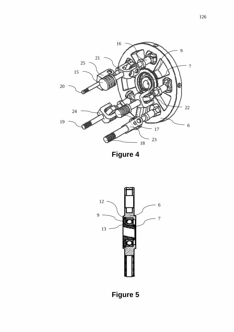
126
16
Figure 4
Figure 5
15
17
18
19
20
6
7
9 21
25
22 24
23
12 6
7 9
13
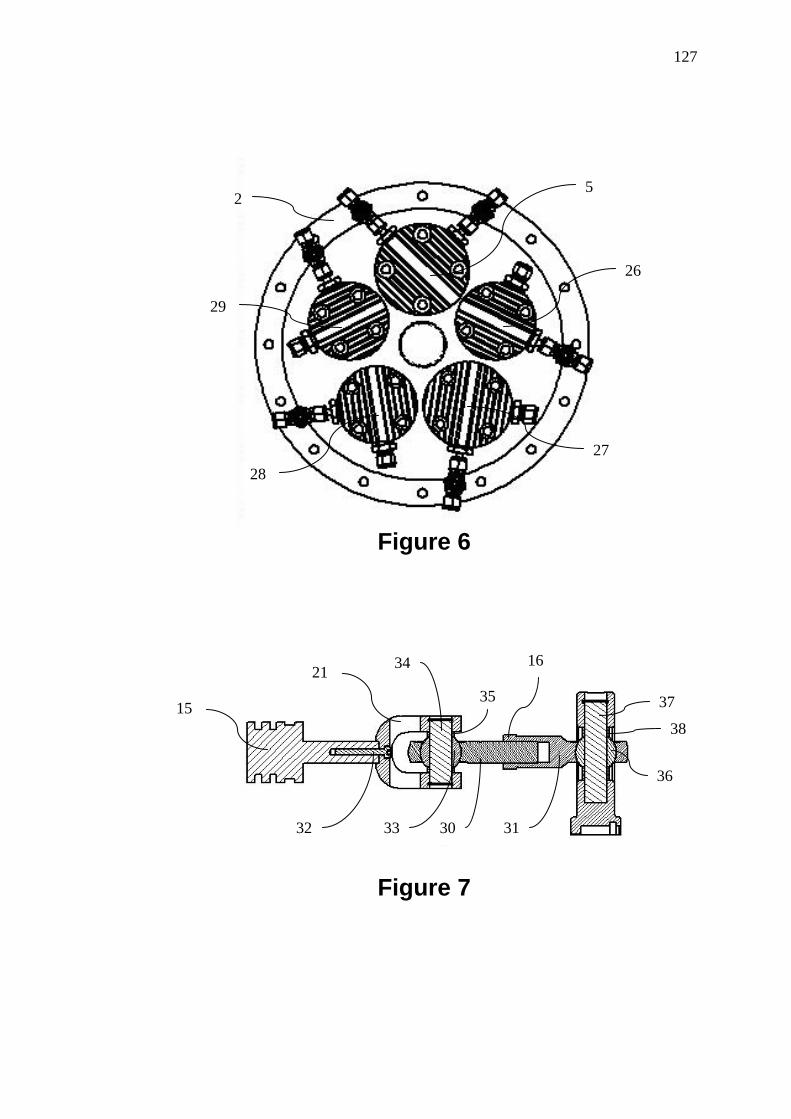
127
5 2
26
29
27 28
Figure 6
16
Figure 7
15
21 34
35 37
38
30
36
32 33 31

128
40 5
43
Figure 8
Figure 9
46
45
44
42
41