deploying the hitachi nas platform in vmware vsphere ... · brocade 48000 switch : director-class...
TRANSCRIPT

Deploying the Hitachi NAS Platform in VMware vSphere Environments Using the Hitachi Adaptable Modular Storage 2000 Family Implementation Guide
By Bob Ingram and Ken Ewers
December 2009

Summary Explosive growth in NAS filers that is required to meet user demand results in administrative headaches and increasing equipment costs. Deploying VMware vSphere 4 on the Hitachi NAS Platform 3080 and 3090, powered by BlueArc®, can reduce those costs. Managing virtual disks is easier than managing logical units (LUs) in a SAN environment, and deploying a Hitachi NAS Platform 3080 or 3090 system instead of deploying multiple smaller NAS systems reduces overall management complexity, improves performance, and lowers energy consumption.
This paper describes how to deploy the Hitachi NAS Platform 3080 and 3090 with the Hitachi Adaptable Modular Storage 2000 family of storage systems in vSphere 4 environments. This solution enables you to centralize management and consolidate the storage used in vSphere 4 environments.
This paper describes how to implement this solution and provides some of the best practices for designing a solution for medium to large enterprise environments. It is written for IT administrators responsible for storage and virtualized environments. It assumes familiarity with managing NAS devices, general storage management practices and familiarity with vSphere.
For best results use Acrobat Reader 8.0.

Contributors The information included in this document represents the expertise, feedback and suggestions of a number of skilled practitioners. The authors recognize and sincerely thank the following contributors and reviewers of this document:
• Steve Burns
• Ron-An Lee
• Lisa Pampuch
• Gokula Rangarajan
Table of Contents Solution Overview ................................................................................................................................................................ 1
Tested Deployment .............................................................................................................................................................. 2
Deploying the Solution ........................................................................................................................................................ 4
Launching the 2000 Family Management Interface ................................................................................................. 4
Launching the Hitachi NAS Platform Management Interface ................................................................................... 5
Configuring the SAN ................................................................................................................................................ 5
Configuring the Hitachi Adaptable Modular Storage 2000 Family ............................................................................ 6
Hitachi NAS Platform Storage Management Stack .................................................................................................. 8
Configuring the Hitachi NAS Platform ...................................................................................................................... 9
Using the Hitachi NAS Platform on vSphere .......................................................................................................... 16
Best Practices ..................................................................................................................................................................... 24
Best Practices for the Hitachi Adaptable Modular Storage 2000 family ................................................................. 24
Best Practices for the Hitachi NAS Platform ........................................................................................................... 25

Deploying the Hitachi NAS Platform in VMware vSphere Environments Using the Hitachi Adaptable Modular Storage 2000 Family Implementation Guide
IT administrators often deploy file systems on NAS because managing file systems on NAS generally requires less administration than managing file systems on SAN devices. While deploying and managing a few NAS filers might be relatively painless, as storage demands grow, the explosive growth in NAS filers that is required to meet user demand results in administrative headaches and increasing equipment costs.
Deploying VMware vSphere 4 on the Hitachi NAS Platform 3080 and 3090, powered by BlueArc®, can reduce those costs. Managing virtual disks is easier than managing logical units (LUs) in a SAN environment, and deploying a Hitachi NAS Platform 3080 or 3090 system instead of deploying multiple smaller NAS systems reduces overall management complexity, improves performance, and lowers energy consumption.
This paper describes how to deploy the Hitachi NAS Platform 3080 and 3090 with the Hitachi Adaptable Modular Storage 2000 family of storage systems in vSphere 4 environments. This solution enables you to centralize management and consolidate the storage used in vSphere 4 environments.
This paper describes how to implement this solution and provides some of the best practices for designing a solution for medium to large enterprise environments. It is written for IT administrators responsible for storage and virtualized environments. It assumes familiarity with managing NAS devices, general storage management practices and familiarity with vSphere.
Solution Overview The solution was tested in Hitachi Data Systems labs using a Hitachi NAS Platform 3090, a Hitachi Adaptable Modular Storage 2300 and a Dell R905 host running vSphere 4. This white paper provides a step-by-step instructions demonstrating deploying two guest virtual machines (VMs) running Windows 2003 R2 and Red Hat Linux 5.4.
While Hitachi Data Systems testing used a Hitachi NAS Platform 3090, the Hitachi NAS Platform 3080 can also be used to deploy this solution, using the same procedures provided in this white paper. In addition, while Hitachi Data Systems testing used an Adaptable Modular Storage 2300, any member of the Hitachi Adaptable Modular Storage 2000 family can be used to deploy this solution.
The 2300 presents storage to the Hitachi NAS Platform 3090 and is used to create two file systems, exported as NFS shares to the ESX host, for VMware file systems (VMFS). The first VMFS is populated with .iso images of operating systems for the purpose of deploying guest VMs on the ESX host. The second VMFS is used for vDisks for both operating system boot drives and additional storage on the guest OS. All NFS mapping is done to the ESX host, not to the guest OS.
1

vSphere 4 can access an NFS volume for a number of storage uses. These can include, but are not limited to, the following:
• Shared unstructured data on VMFS file systems. The solution described in this white paper uses the VMFS file systems to store .iso images for deployment of operating systems.
• Booting of virtual machines from vDisks on NFS datastores.
The midrange Hitachi NAS Platform 3080 and 3090 deliver best-in-class performance and scalability. They can provide a centrally managed storage pool, increasing utilization, simplifying management and increasing productivity. Managing NFS in a vSphere environment can be simpler than managing many Fibre Channel logical units (LUs). Applications or file system types can be grouped into a single file system and distributed in the vSphere environment. Environments that use a few ESX hosts to run a few dozen virtual machines offer little administrative advantage for using the Hitachi NAS Platform instead of Fiber Channel LUs, but as vSphere environments grow into hundreds of virtual machines distributed across multiple ESX hosts, managing LUs can be complex and labor intensive.
Tested Deployment This section describes the hardware and software used in Hitachi Data Systems laboratory testing of this solution. Table 1 describes the hardware used in testing this solution.
Table 1. Tested Deployment Hardware
Hardware Details
Hitachi Adaptable Modular Storage 2300 storage system
Dual controllers 4 4GB Fibre Channel ports, 2 per controller 8GB cache memory, 4GB per controller 20 146GB, 15K RPM, SAS disks Microcode version 0870/C-M
Brocade 48000 switch Director-class SAN switch with 4Gb Fibre Channel ports FOS 5.3.1a
Hitachi NAS Platform 3090 storage system
Network attached storage (NAS) platform using 1 10GbE port, 4 4Gbit/s Fibre Channel ports and 32GB distributed memory Firmware 6.5.1847.16
Dell PowerEdge R905 server 64GB memory, 4 quad-core AMD processors BIOS 3.0.2
2

Table 2 lists the software used in deploying this solution.
Table 2. Tested Deployment Software
Software Details Version
Hitachi Storage Navigator Modular 2 Storage management GUI and CLI Included with the Hitachi Basic Operating System Package
7.01
VMware vCenter server vSphere management 4.0.0 build 140742
VMware Virtual Infrastructure Client vSphere management 4.0.0
VMware ESX Host operating system that provides a virtualization layer to support sharing of multiple virtual machines
4.0.0 build 164009
Microsoft Windows 2003 Operating system for virtual machine 2003 SP2 - 32 bit
Red Hat Linux Operating system for virtual machine 5.1 - 64 bit
Figure 1 illustrates the tested deployment.
Figure 1. Tested Deployment
3

Deploying the Solution To deploy this solution, follow these high-level steps:
1. Connect the Hitachi Adaptable Modular Storage 2000 family storage system to the SAN switch or directly to the Hitachi NAS Platform 3090.
2. Install and launch the 2000 family and Hitachi NAS 3090 management interfaces.
3. Connect the Hitachi NAS Platform 3090 to the SAN switch or directly to the 2000 family storage system.
4. Configure the Fibre Channel ports on the 2000 family storage system.
5. Configure the Fibre Channel ports on the Hitachi NAS Platform 3090.
6. Zone the SAN switch if applicable.
Because of the many type of SAN switches available, this configuration is not described in this document. For more information, see your SAN switch documentation.
Hitachi Data System recommends that each initiator (Hitachi NAS Platform Fibre Channel port) be placed in a separate zone. This zone contains the Fibre Channel port on the 2000 family storage where LUs will be presented.
7. Configure the 2000 family storage LUs.
8. Configure the Hitachi NAS Platform 3090 storage pools, file systems and NFS exports.
9. Map the NFS exports to the ESX hosts.
Launching the 2000 Family Management Interface Use Hitachi Storage Navigator Modular 2 software to connect to and manage the 2000 family storage system used in this solution. To connect to the 2000 family storage system, follow these steps:
1. Install Storage Navigator Modular 2 software. For installation instructions, see the installation guide that accompanies the software.
2. Using a Java-enabled browser, connect to the following URL: http://<IP address of Storage Navigator Modular 2
host>:23015/StorageNavigatorModular/Login
3. Log in using the user name and password. The default user name is system and the default password is manager.
4. Click the Add Array button at the bottom of the window.
5. Follow the wizard’s prompts to add the 2000 family storage system to Storage Navigator Modular 2 software.
6. Click the 2000 family storage system name to connect to and manage the storage.
4

Launching the Hitachi NAS Platform Management Interface To connect and manage the Hitachi NAS Platform, use the internal or the external Server Management Unit Web Manager interface (SMU). For more information, see the installation guide that accompanies the Hitachi NAS system. Server/cluster management is performed through Web Manager (a browser‐based graphical user interface)
1. Open a Web browser and enter the public IP address of the SMU GUI in the address field.
2. Log in using the user name and password. The default user name is admin and the default password is nasadmin.
3. Select the Hitachi NAS platform to be managed from the Server Status Console drop-down menu.
Note that some of the Fibre Channel port configuration must be done using the command-line interface (CLI). The CLI can be accessed in the following ways:
– Preferred method, using Secure Shell (SSH) to connect to the Hitachi NAS Platform server through the SMU
– Using the SSC utility, available for Windows and Linux
– Using the Perl SSC utility (PSSC), available for all other UNIX operating systems
When logging in to the SMU via the CLI, the default username is manager and the default password is nasadmin.
Configuring the SAN To begin this deployment, connect all Fibre Channel ports from the Hitachi NAS Platform and 2000 family storage system to the SAN switch. If you do not use the optional SAN switch, the Fibre Channel ports can be directly connected from the Hitachi NAS Platform Fibre Channel ports to the 2000 family storage system’s Fibre Channel ports. After the physical connections are complete, configure a point-to-point connect to the switches from the 2000 family storage system’s Fibre Channel ports and Hitachi NAS Platform’s storage ports.
Configuring the Storage System Fibre Channel Ports To configure the storage system’s Fibre Channel ports, follow these steps:
1. Log on to Storage Navigator Modular 2 software.
2. Click the 2000 family storage system to be configured.
3. Click the Settings link and the FC Settings link and choose a connection type as follows:
– SAN switch connection — Set the Fibre Channel port to point-to-point and the transfer rate to match the SAN switch.
– Direct connection — Set the Fibre Channel port to loop and the transfer rate to 4Gbps.
5

Configuring the Hitachi NAS Platform Fibre Channel Ports To configure the Hitachi NAS Platform Fibre Channel ports, follow these steps:
1. Connect to the SMU CLI. The default user name is manager and the default password is bluearc.
2. Select the Hitachi NAS Platform system to be configured from the list presented.
3. Configure the Fibre Channel ports for connectivity, as follows: To configure for SAN switch connection, configure the Fibre Channel ports as N-Ports, as follows: fc-link-type -t N To configure for direct connection, configure the Fibre Channel ports as Node-Loop ports, as follows: fc-link-type -t NL This command sets all the Fibre Channel ports to the type N-port. The Fibre Channel ports are numbered 1, 2, 3 and 4. To configure a single Fibre Channel port, specify –i <port number> on the command line, as follows: fc-link-type –i 1 -t N
Configuring the Hitachi Adaptable Modular Storage 2000 Family To configure the 2000 family storage system, follow these high-level steps:
1. Log in to Storage Navigator Modular 2 software and connect to the 2000 family.
2. Create the RAID groups to be utilized by the Hitachi NAS Platform.
3. Create the LU to be utilized by the Hitachi NAS Platform.
4. Create the host groups on the Fibre Channel ports.
5. Add the LUs to the host groups.
Creating RAID Groups Before creating RAID groups, examine your expected workload. For example, if you plan to use these RAID groups for storage of .iso images, read performance is more important than write performance, meaning that RAID-5 or RAID-6 is the best choice.
For more information about RAID levels, see the ”Best Practices” section in this document.
1. Using the Storage Navigator Modular 2 software GUI, connect to the 2000 family storage system by clicking the Array Name link.
2. Choose Groups > Logical Units and click the RAID Groups tab.
3. Click the Create RG button.
6

4. Select a RAID level and combination.
Leave the Number of Parity Groups and Automatic Selection at the default settings.
For more information, see the “Best Practices” section of this document.
5. Select the drive type and drive capacity needed.
NOTE: The 2000 family selects the next available disks of the size and type requested.
6. Click OK.
7. Repeat until the needed number of RAID groups exists.
Creating LUs on RAID Groups To create LUs on RAID groups, follow these steps:
1. Log in to Storage Navigator Modular 2 software and connect to the 2000 family.
2. Navigate to Logical Units.
3. Click the Create LU button.
4. Select a RAID group in which to place the LU.
5. Note the value in the LUN field.
You can choose to keep this LU number for or change it to any LU number from 0000 to 4096 that is not already used by another LU.
Document the LU number used for future reference.
6. Use one LU per RAID group and click OK.
NOTE: The new LU begins formatting. However, it is available for immediate use.
Creating Host Groups Host groups (host storage domains) are a feature of 2000 family storage that allows your storage systems to be more easily managed. You can assign world wide names (WWNs) to a host group and the desired LUs can be associated with each host group. By default, each port contains one host group that can be used.
For solutions where the Hitachi NAS is directly connected to the 2000 family system or where the Fibre Channel ports on the 2000 family are not shared with other hosts or devices, host groups are not needed. Set host group security to disabled and use the default host group.
The host LUN (H-LUN) is the LU number presented to the host.
1. Using the Storage Navigator Modular 2 software GUI, connect to the 2000 family storage system by clicking the Array Name link.
2. Choose Groups > Host Groups.
3. Click the Host Group Security tab and verify that host group security is enabled on the Fibre Channel ports to be used. If host group security is not enabled, select the port’s radio button and click the Change Host Group Security button to enable it.
7

4. Click the Create Host Group button.
5. Select all of the Fibre Channel ports that will be used for the Hitachi NAS Platform.
6. Enter a name for the host group in the Name field.
7. Select all of the WWNs associated with the Hitachi NAS Platform and click the Add > button.
For more information about how to obtain the WWNs for the Hitachi NAS Platform, see the “Configuring the Hitachi NAS Platform” section of this white paper.
8. Click the Logical Units tab.
9. Select the beginning H-LUN number radio button.
10. Select all the check boxes for LUs to be presented to the Hitachi NAS Platform and click the Add > button.
No changes are required in the Options tab for Hitachi NAS Platform configuration.
11. Click OK.
Configuration of the 2000 family storage system is complete. No changes in options are required, standard mode is used. If you need to make changes to the host groups at a later time, for example, to add additional LUs to the host group, use the Edit Host Group button.
Hitachi NAS Platform Storage Management Stack The Hitachi NAS Platform storage management stack consists of a system drive (SD), a system drive group (SDG), a storage pool (SP) and a file system. An LU presented from the 2000 family storage system to the Hitachi NAS Platform is called a system drive.
A system drive group is a mechanism for telling the Hitachi NAS Platform which SDs are in which RAID group in the 2000 family so that it can avoid writing to several members of the same RAID group at once, thus decreasing the head movement. Before a system drive can be active and belong to a storage pool, it must belong to an SDG. When a RAID group has one LU, one SD per SDG is used.
A storage pool is a logical container for one or more system drives. An SP can be expanded by adding SDs to the pool. An SP can grow up to 256TB and contain up to 128 file systems.
A file system is the primary storage component in the Hitachi NAS Platform. All other features either directly or indirectly support file systems. A standalone Hitachi NAS Platform can support up to 128 file systems and a clustered Hitachi NAS Platform can support up to 125 file systems.
8

Figure 7 illustrates the Hitachi NAS Platform storage management components; it does not include the VMware file system.
Figure 7. Hitachi NAS Platform Storage Management Components
For more information about Hitachi NAS Platform storage management, see the “Best Practices” section in this document.
Configuring the Hitachi NAS Platform In this deployment guide assumes that your Hitachi NAS Platform and SMU hardware are installed and the initial configuration is complete. For more information about these steps, see the Hitachi NAS Platform installation guide. To configure the Hitachi NAS Platform, follow these high-level steps:
1. Log in to the SMU using a Web browser.
2. Connect to the Hitachi NAS Platform system to be configured in the Server Status Console.
3. Create the link aggregation on the 10Gb or 1Gb Ethernet ports.
4. Create the enterprise virtual server (EVS). The EVS appears to the clients as an actual server. It contains an IP address, file systems and NFS shares.
5. Configure the SP and file systems.
6. Export the NFS shares.
Configuring the Hitachi NAS Platform Network for File Services Each Hitachi NAS Platform system is equipped with six 1Gb Ethernet (GbE) ports, two 10Gb Ethernet (10GbE) ports for file serving and two 10/100/1000 Ethernet ports, one public (eth0) and one private (eth1), both used for management. All of these ports support jumbo frames and can be configured either individually or trunked (LACP) together (1Gbit ports in a one trunk and 10Gbit ports in a separate trunk). In this solution one 10Gbps port is used, we are not using jumbo frames and using the port as an individual port, with a unique IP address. For more information about jumbo frames, see the Hitachi NAS Platform administrator’s guide located on the home page of the SMU.
9

Hitachi NAS Platform systems support two port level load balancing methods:
• Normal — The server routes all traffic for a given “conversation” through one of the physical ports in the appropriate aggregation. The server’s hash and routing functions determine which packets use which physical ports of the aggregation. For example, all traffic for a particular TCP connection is always routed through the same physical port (unless the link drops).
• Round Robin — The packets making up the traffic are routed through the ports in sequential order. For example, the first packet goes down the first port, the second packet goes down the next port and so on until all ports have been used. Then the traffic starts again at the first port. This routing scheme ensures that all the ports are more or less equally used, to provide maximum link throughput.
Network clients access the Hitachi NAS Platform system's file services through one or more EVS IP addresses, which are accessible through the 10 GbE ports, the GbE ports or both. Multiple IP addresses can be assigned for file services.
The following procedure describes how to configure the public data network by creating a link aggregation. Note that this procedure describes how to set up a 10GbE port. If a 1GbE port is used, then adjust the procedure accordingly.
To create a link aggregation, follow these steps;
1. From the SMU GUI Home page, click the Network Configuration link, the Link Aggregation link, then the Add Link Aggregation link.
2. Select the radio button for the Link Aggregate name.
3. Select a port by placing a checkmark in the box.
4. Select the Normal radio button under the Port Level Load Balancing heading.
Because this solution does not use LACP, use normal port level load balancing. Round robin is used with LACP trunking.
10

Creating an EVS The EVS appears to network clients as the virtual file server. Like a physical server, an EVS has an IP address, contains file systems and supports CIFS shares and NFS exports. VMware ESX uses NFS exports. A single physical Hitachi NAS Platform node or a Hitachi NAS Platform cluster can have up to 64 enterprise virtual servers. You can add, delete, or change enterprise virtual servers based on the evolving needs of your environment. This solution uses one EVS.
To create an EVS, follow these steps:
1. Log in to the SMU.
2. From the SMU GUI Home page, click the Server Settings link, the EVS Management link and the Add button.
3. Enter a name, for example, EVS1. You use this name to identify different enterprise virtual servers on the Hitachi NAS Platform.
4. Provide the IP address and subnet mask for this EVS.
5. Select the 10GbE ports to which this IP address can be assigned.
6. Select the aggregate in the Port drop-down menu, for example, ag1, and click OK.
11

Configuring the Hitachi NAS Platform To configure the system drives, storage pools and file systems for use by the vSphere ESX hosts, follow these steps:
1. Use the SMU GUI to display the system drives (SD).
2. From the SMU GUI Home page, click the Home link, the Storage Management link and the System Drives link.
3. Select the check boxes for the SDs to be used and click the allow access button.
4. From the SMU GUI home page, click the Storage Management link and the System Drive Group link.
5. Click Create.
6. Highlight the SDs to be in the SDG, click the ►icon and click OK.
To create this one SD per SDG mapping quickly, you can use the CLI. For example to assign SDs 0 to 12 to separate SDGs use the following command:
cn all sd-group-alone 0-12
7. From the SMU GUI home page, click the Storage Management link and the Storage Pool link.
12

8. Click Create the storage pool button.
9. From the SMU GUI Home page, click the Storage Management link and the Storage Pool Wizard link.
10. Select the SDs for the SP, enter a storage pool label, accept the chunk size default or input the desired chunk size and click the next button.
For more information about chunk sizes, see the Hitachi NAS Platform administrator’s guide, which is located on the SMU home page under the “Documentation” heading.
11. Double check the configuration and click the create button.
12. When asked if you want to add a file system to your new storage pool, click yes if you are using WFS-1 file systems or no if you are creating the preferred WFS-2 file system. The Create File System screen displays.
13. Click OK.
13

Creating a WFS-2 File System
The WFS-2 file system is the preferred file system for the Hitachi NAS Platform. Note that formatting a Hitachi NAS Platform file system with WFS-2 type is currently supported only through SMU CLI. However WFS-1, which is the default file system supported by the Hitachi NAS Platform, can be created through either CLI or GUI.
File system block size of 32KB is used when large files are to be stored on the share, use 4KB when small files are stored. When a mix of large and small files is used, of the file size is unknown, use 4KB.
When choosing which Hitachi NAS Platform file system block size to use, both space utilization and performance should be considered. Even though 32KB block file systems always provide much better MB/sec performance, the drawback is that when the client file size is only 2KB or 4KB, a lot of disk space is wasted at the file system level. Therefore, the decision of using a 4KB or 32KB file system block size depends on your performance requirements versus your space utilization requirements.
To create and format the WFS-2 file system, follow these steps:
1. Log in to SMU.
2. Execute the Hitachi NAS Platform vn command as follows:
vn 1 filesystem-create sp-name fs-name <xx> <yy> <xx> is the file system size and <yy> is the confine size. For more information, see the man page for this command.
3. Execute the Hitachi NAS Platform vn command as follows:
vn 1 format –confirm –wfs 2 -b <xx> fs-name
<xx> is the file system block size. You can choose 4 or 32.
Disabling Read Ahead
Because of the random nature of vSphere 4 I/O, read ahead has no benefit in this environment. Run the following Hitachi NAS Platform command to disable read ahead:
read-ahead --chunk-size 0 --max-read-ahead 0
14
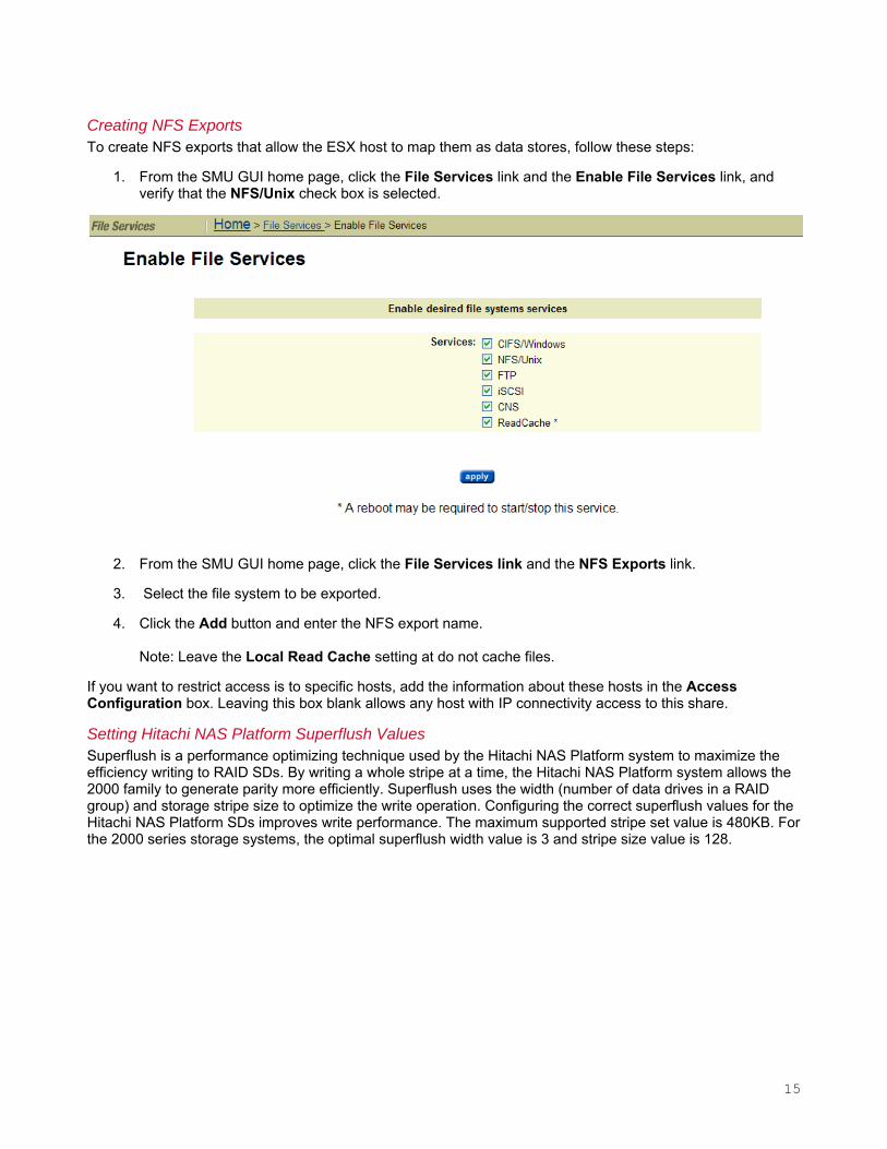
Creating NFS Exports To create NFS exports that allow the ESX host to map them as data stores, follow these steps:
1. From the SMU GUI home page, click the File Services link and the Enable File Services link, and verify that the NFS/Unix check box is selected.
2. From the SMU GUI home page, click the File Services link and the NFS Exports link.
3. Select the file system to be exported.
4. Click the Add button and enter the NFS export name. Note: Leave the Local Read Cache setting at do not cache files.
If you want to restrict access is to specific hosts, add the information about these hosts in the Access Configuration box. Leaving this box blank allows any host with IP connectivity access to this share.
Setting Hitachi NAS Platform Superflush Values Superflush is a performance optimizing technique used by the Hitachi NAS Platform system to maximize the efficiency writing to RAID SDs. By writing a whole stripe at a time, the Hitachi NAS Platform system allows the 2000 family to generate parity more efficiently. Superflush uses the width (number of data drives in a RAID group) and storage stripe size to optimize the write operation. Configuring the correct superflush values for the Hitachi NAS Platform SDs improves write performance. The maximum supported stripe set value is 480KB. For the 2000 series storage systems, the optimal superflush width value is 3 and stripe size value is 128.
15

To set superflush values, follow these steps:
1. From the SMU GUI, go to Storage Management, click the System Drives link and the System Drive Details link.
2. Enter 128 in the Stripe Size field and 3 in the Width field and click the apply button.
Using the Hitachi NAS Platform on vSphere After the 2000 family storage and Hitachi NAS Platform configurations are complete, you can map the shares and use them on the ESX host. This white paper describes two ways you can use shares:
• A share called ISO is used to store .iso images of operating system installation DVDs.
• A share called VMFS is used as a VMFS to contain vDisks. These vDisks act as the boot drive for a Windows guest and a Linux guest or vDisks for additional storage.
Creating a VMkernel Port vSphere 4 uses a network port called a VMkernel port for communication with NFS shares, vMotion and iSCSI. Hitachi Data Systems recommends using a private network or VLAN to provide network isolation. In vSphere 4 environments with multiple ESX or ESXi hosts managed by vCenter, you can use a vNetwork distributed switch to simplify management. This procedure is for a vSphere 4 host using vNetwork standard switch (vSwitch). For more information about using a vNetwork distributed switch configuration, see VMware technical publications.
To create the VMkernel port, follow these steps:
1. Use the VI client to log into vCenter or the ESX host. If using vCenter, navigate to the ESX host.
2. Click the Configuration tab and the Networking link.
3. Click the Add Networking link.
4. Select the VMkernel radio button and click Next ≥.
16

5. Select the NIC and click Next ≥.
6. Enter the VLAN ID, if applicable, and click Next ≥.
7. Enter the IP address parameters and click Next ≥.
8. Follow the remaining prompts from the wizard.
Note: If another VMkernel port exists on a shared network, remove it to prevent the NFS mount from using the incorrect network.
Extending the Number of NFS Mounts By default, ESX allows a maximum of eight NFS mounts at a time. This can be extended to 64.
1. Log into In the VI client.
2. Highlight the ESX host.
3. Click the Configuration tab.
4. Go to Software and click the Advanced Settings link.
5. Select NFS from the tree on the left side of the window.
6. Scroll down to the NFS.MaxVolumes field and enter the number required.
Note that the ESX host must be rebooted for this to take effect.
17

Mapping the NFS Share to vSphere and Copying .iso Images This solution uses two NFS shares from the Hitachi NAS Platform system. Hitachi Data Systems testing used vCenter 4.0.0 GUI and the Virtual Infrastructure (VI) client for all vSphere operations.
1. Log in to vCenter using the VI client.
2. Go to the Datastores view.
3. Right-click the data center where the NFS mount will be added.
4. Select the ESX host where the NFS share will be added.
5. Select the Network File System radio button and click Next.
6. Complete the Server, Folder and Datastore Name fields, and click Next. Note that IP address or host name can be used.
Do not select the Mount NFS read only check box at this time.
NOTE: ESX does not require setting read or write block size. It transfers NFS blocks in the size that the NFS filer advertises. No option settings are required.
18

7. Review the summary and click Finish.
To add .iso images to the ISO datastore, the PC running the VI client needs access to these .iso images. They can be on the local host or a network drive.
8. In vCenter, navigate to the datastore, right-click it and click Browse Datastore.
9. (Optional) Create a folder and open this location for storing the files.
10. Click the Upload files to this datastore button.
11. Select Upload Files or Upload Folder from the drop-down menu.
12. Select the files or folder to upload and click Open.
13. After all .iso images are copied, disconnect the ISO datastore and map it again as read only by checking the Mount NFS as read only check box.
Deploying a Virtual Machine from the .iso File To deploy a virtual machine with a vDisk that resides on an NFS-mapped datastore, follow these steps:
1. Log in to vCenter.
2. Map the NFS mount to be used as an OS boot drive datastore to the ESX host where the VM will be deployed. If this VM will be in a clustered environment, mount this share on every ESX host in the cluster.
19

3. Right-click an ESX host, cluster or data center and choose New Virtual Machine from the drop-down menu.
4. Select the Typical or Custom radio button and click Next.
5. Enter the VM name, highlight the inventory location and click Next.
6. Highlight the datastore in the Select a datastore in which to store the virtual machine files pane and click Next.
7. Select the OS from the list that matches the .iso file to be mounted and click Next.
8. Select the size of the vDisk required, select GB or MB from the Virtual disk size drop-down menus and click Next.
Note that the Allocate and commit space on demand check box is dimmed because NFS vDisks are allocated as thin.
The Support clustering features such as Fault Tolerance check box is dimmed because this feature is determined by the NFS server.
9. In the Ready to Complete window, select the Edit the virtual machine settings before completion check box and click Continue.
10. Highlight CD/DVD Drive 1, select the Connect at power on and the Datastore ISO File check box and click Browse.
11. Browse to the .iso file to be used as install media and click OK.
20

12. Click OK.
VM creation is complete. The VM is ready for you to boot and install the OS. If a DVD change is required during installation, highlight the virtual machine and click the Edit Settings link and browse to the second .iso image.
21

Adding a vDisk from the NFS share If you need additional vDisks (.vmdk) on NFS shares, follow these steps:
1. Highlight the virtual machine and click the Edit Settings link in vCenter or VI client.
2. Click Add.
3. Highlight Hard Disk and click the Next ≥ button.
4. Select the Create new virtual disk radio button and click the Next ≥ button.
22

If you need a different SCSI node, for example, if you plan to use a different virtual SCSI controller, select it from the drop-down menu.
5. Select the Specify a datastore radio button, browse to the NFS datastore where the vDisk will be located and click OK.
6. Complete the Disk size field and click the Next ≥ button.
7. In the Virtual Device Node field, note the SCSI node used.
23

9. Review the settings and click the Finish button.
ted in Hitachi Data Systems labs and validated for the best performance and
RAID levels for a variety of workloads. Follow these best practices for SAS
for storage of archival data or seldom used data. SATA disk are less expensive than SAS
RG GUI in Storage Navigator Modular 2 software has selections for RAID level, combination, s:
riting to several members of the same RAID group at once,
RAID type Best Practice Recomended Usage
8. Click the Next ≥ button.
Best Practices The following practices were tesease of administration.
Best Practices for the Hitachi Adaptable Modular Storage 2000 family The 2000 family supports several and SATA disks:
• Use SAS disks for OS, application and online data. SAS disks provide superior performance to SATA.
• Use SATA disksdisks.
• For storage of .iso images of OS and application software, SAS or SATA disks can be utilized.
The Create number of parity groups and the choice of automatic or manual selection. Follow these best practice
• For number of parity groups, leave this field at 1.
• For the automatic or manual selection radio button, this setting can be left at automatic.
• Configure only one LU per RAID group to avoid wthus decreasing the head movement
Table 2 describes the RAID level, minimum and maximum number of data (D) and parity (P) disks supported and recommendations on their usage and optimal number of disks for each RAID type.
Table 2. Hitachi Adaptable Modular Storage 2000 Family RAID Levels
Combination
RAID-5 8D+1P Use RAID-5 when yoperformance and good
u require the highest read write performance.
RAID-1+0 e 2D+2D Use RAID-1+0 when you require high write performancand good read performance.
RAID-6 8D+2P Use RAID-6 for maximum data protection when maximum performance is not required. Excellent for SATA.
Configure only one LU per RAID group to avoid writing to several members of the same RAID group at once, us decreasing the head movement. If the required LU sizes do not allow for this configuration, use system
s on the Hitachi NAS Platform 3080 and 3090. For more information, see the “Best Practices for thdrive groupHitachi NAS Platform” section in this document.
24

Best Practices for the Hitachi NAS Platform This section provides best practices for deploying the Hitachi NAS Platform with the Adaptable Modular Storage 2000 family and vSphere 4.
Storage Pool Provide a minimum of four SDs to the storage pool to achieve the performance benefit of striping within the Hitachi NAS Platform. When creating a storage pool, the Hitachi NAS Platform stripes (RAID-0) the system drives together using a 4MB stripe. When I/O is issued to the storage pool, it is sent to the underlying stripe.
For optimum performance, use one file system per storage pool.
Tunable Parameters Follow these best practices when setting tunable parameters:
• For use on the Hitachi NAS Platform, the default chunk size of 256K on the 2000 family storage RAID is optimal.
• A superflush value of 3 x 128 is optimal as determined by the Hitachi Data Systems performance labs.
• Link aggregate:
– When creating one aggregate on each 10GbE port or on each 1GbE, select normal as the load.
– When using LACP, select multiple ports and round robin as the load.
25

26
Corporate Headquarters 750 Central Expressway, Santa Clara, California 95050-2627 USA Contact Information: + 1 408 970 1000 www.hds.com / [email protected]
Asia Pacific and Americas 750 Central Expressway, Santa Clara, California 95050-2627 USA Contact Information: + 1 408 970 1000 www.hds.com / [email protected]
Europe Headquarters Sefton Park, Stoke Poges, Buckinghamshire SL2 4HD United Kingdom Contact Information: + 44 (0) 1753 618000 www.hds.com / [email protected]
Hitachi is a registered trademark of Hitachi, Ltd., in the United States and other countries. Hitachi Data Systems is a registered trademark and service mark of Hitachi, Ltd., in the United States and other countries.
All other trademarks, service marks and company names mentioned in this document or Web site are properties of their respective owners.
Notice: This document is for informational purposes only, and does not set forth any warranty, expressed or implied, concerning any equipment or service offered or to be offered by Hitachi Data Systems. This document describes some capabilities that are conditioned on a maintenance contract with Hitachi Data Systems being in effect and that may be configuration dependent, and features that may not be currently available. Contact your local Hitachi Data Systems sales office for information on feature and product availability. © Hitachi Data Systems Corporation 2009. All Rights Reserved. AS-028-00 December 2009