department of mechanical engineeringlibrary.bec.ac.in/kbc/notes bec/mech/6 sem/cad cam lab...
TRANSCRIPT
BHARATHIDASAN ENGINEERING COLLEGE
NATTRAMPALLI
Department of Mechanical Engineering
Subject Code/Title: ME6611 C.A.D. / C.A.M. Laboratory
Name : ………………………………………
Reg No : ………………………………………
Branch : ………………………………………
Year & Semester : ………………………………………

EX.NO
DATE
EXERCISES
PAGE NO MARKS
AWARDED STAFF
SIGNATURE
CAD EXERCISES
1 EXERCISE ON EXTRUSION
2 EXERCISE ON REVOLVE
3 EXERCISE ON RIB
4 EXERCISE ON SHELL
5 ASSEMBLY ON UNIVERSAL COUPLING
6 ASSEMBLY OF KNUCKLE JOINT
7 ASSEMBLY OF FLANGE COUPLING
8 ASSEMBLY OF PLUMMER BLOCK
9 ASSEMBLY OF CROSS HEAD
10 ASSEMBLY OF SCREW JACK
11 ASSEMBLY OF CONNECTING ROD
12 ASSEMBLY OF STUFFING BOX
13 ASSEMBLY OF MACHINE VICE
CAM EXERCISES
1 STUDY OF “G” CODES AND “M” CODES
2 CNC-MILLING RECTANGULAR POCKETING
3 CNC-MILLING CIRCULAR POCKETING
4 CNC-SIMPLE TURNING
5 CNC-STEP TURNING
6 CNC LATHE –SIMPLE FACING
7 CNC LATHE –RIGHT HAND TAPER TURNING
8 CNC LATHE –LEFT HAND TAPER TURNING
9 CNC LATHE –THREAD CUTTING OPERATION

CAD – MODELING EXERCISES
EXERCISE ON EXTRUSION
EX.NO:1 EXERCISE ON EXTRUSION
DATE:
Aim:
To model the given object using the extrusion feature as per the dimension given.
System Requirements:
Personal computer
Solid modeling software (Solid
Edge) Description of extrusion
Base feature:
The first feature that is created.
The foundation of the part.
The base feature geometry for the base is an extrusion. The extrusion is named
extrude 1.
To create an extruded base feature:
Select a sketch plane.
Extrude the sketch plane perpendicular to the sketch plane.
Extruded boss feature:
It adds material to part and require a sketch.
Extruded cut feature:
It removes material from the part and also it requires a sketch.
Fillet feature:
Round the edge or faces of a part to be at specified radius.
Procedure:
Select a sketch plane (Front, top or side).
Sketch a 2D profile of the model.
Dimension the sketch using smart dimension icon.
Check the sketch is fully defined.
Extrude the sketch perpendicular to the sketch plane.
Use extruded cut feature to cut the solid as given in the diagram.
Result:
Thus the given model is extruded.

EXERCISE ON REVOLVE

EX.NO:2 EXERCISE ON REVOLVE
DATE:
Aim:
To model the given object by using the revolve feature as per the dimension given.
System requirement:
Personal computer
Solid modeling software (solid edge) Description of revolve feature:
Command manager: feature > revolve boss > base
Menu : boss >base > revolve
Tool bar : revolved boss >base
Using this tool,sketch is revolved about the revolution axis.The revolution axis could be
an axis,an entity of the sketch or an edge of another feature to create the revolved
feature.Note that wheather you use a centerline or an edge of another feature to create the
revolved features. Note that wheather you use a centerline or an edge to revolve the sketch
should be drawn on one side of the centerline of the edge.
Procedure:
Select a sketch plane (Front, top or side).
Sketch a 2D profile of the model.
Dimension the sketch using smart dimension icon.
Check the sketch is fully defined. Revolve the sketch.
Result:
Thus the given model is drawn by using the revolve feature.
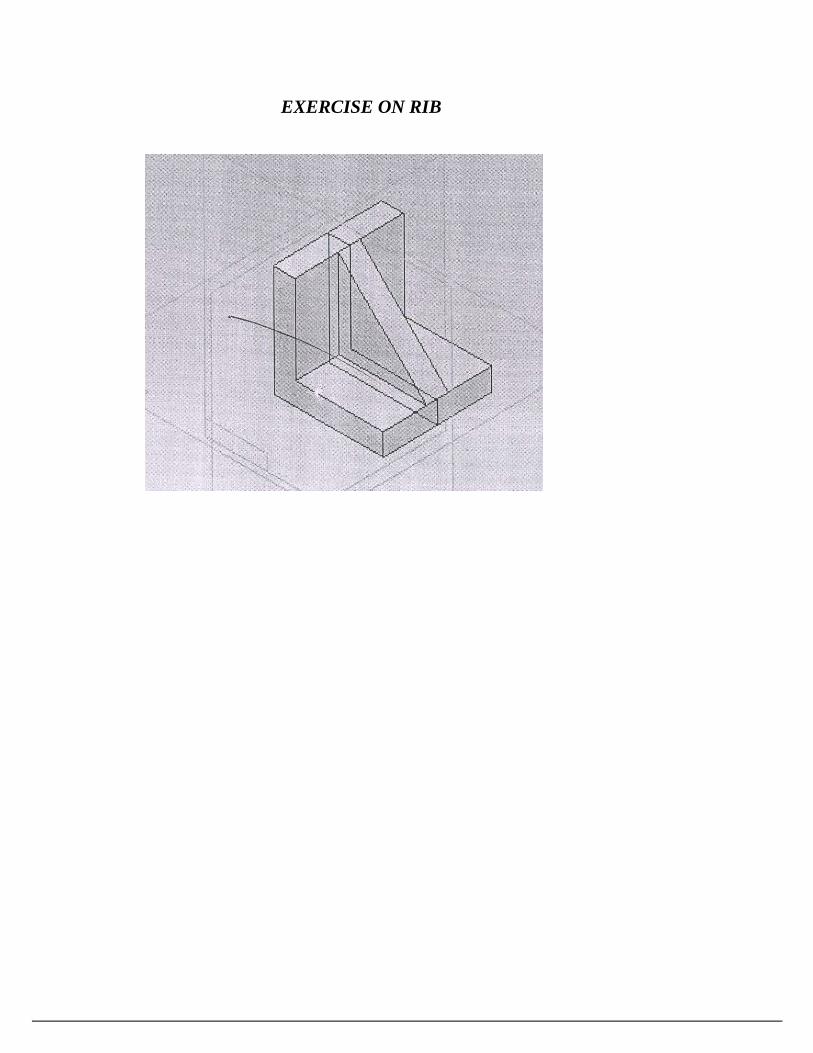
EXERCISE ON RIB
EX.NO:3 EXERCISE ON RIB
DATE:
Aim:
To model the given object and construct the rib portion in it.
System requirement:
Personal computer
Solid modeling software (solid edge) Description of rib feature:
Command manager: feature>rib
Menu : insert>feature>rib
Tool bar : feature>rib
Ribs are defined as the thin walled structures that are used to increase to strength
of the entire structure of the component. So that it does not fall under an increased
load.
In solid works, the ribs are created using an open sketch as well as a closed sketch.
To create a rib feature, invoke the rib property manager and select the plane on
which you need to draw the sketch for creating the rib feature.
Draw the sketch and exit the sketching environment. Specify the rib parameters in
rib property manager and view the detailed preview button. The rib tool is revoked
by choosing the rib button from the features.
Procedure:
Select a sketch plane (Front, top or side).
Sketch a 2D profile of the model.
Dimension the sketch using smart dimension icon.
Check the sketch is fully defined.
Extrude the sketch.
Using rib feature complete the model.
Result:
Thus the given model is drawn and completed using the rib feature.

EXERCISE ON SHELL

EX.NO:4 EXERCISE ON SHELL
DATE:
Aim:
To model the given object and remove the material using shell option.
System requirement:
Personal computer
Solid modeling software (solid edge) Description of rib feature:
Removes material from the selected face.
Creates a hollow block from a solid block.
Very useful for thin walled plastic parts.
You are required to specify a wall thickness when using the shell feature.
Procedure:
Select a sketch plane (Front, top or side).
Sketch a 2D profile of the model.
Dimension the sketch using smart dimension icon.
Check the sketch is fully defined.
Extrude the sketch.
Select a face in which you are going to draw the cut profile.
Make the plane to normal to you.
Sketch the cut profile and dimension it. Use extrude cut feature to remove the
portion Select the shell feature.
Select the face in which material to be removed by using shell. Specify the shell
thickness.
Result:
Thus the given model is drawn and completed using the shell feature.
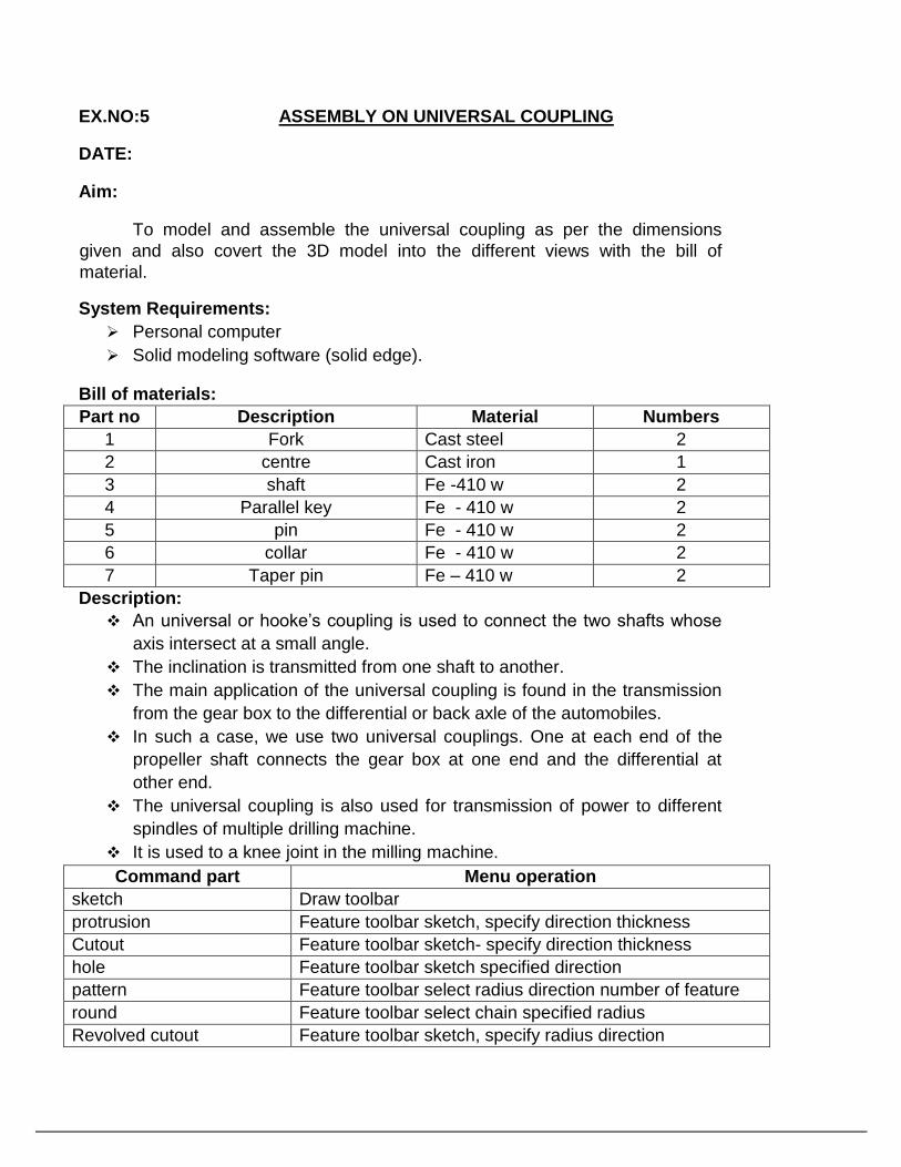
EX.NO:5 ASSEMBLY ON UNIVERSAL COUPLING
DATE:
Aim:
To model and assemble the universal coupling as per the dimensions
given and also covert the 3D model into the different views with the bill of
material.
System Requirements:
Personal computer
Solid modeling software (solid edge).
Bill of materials:
Part no Description Material Numbers
1 Fork Cast steel 2
2 centre Cast iron 1
3 shaft Fe -410 w 2
4 Parallel key Fe - 410 w 2
5 pin Fe - 410 w 2
6 collar Fe - 410 w 2
7 Taper pin Fe – 410 w 2
Description:
An universal or hooke’s coupling is used to connect the two shafts whose
axis intersect at a small angle.
The inclination is transmitted from one shaft to another.
The main application of the universal coupling is found in the transmission
from the gear box to the differential or back axle of the automobiles.
In such a case, we use two universal couplings. One at each end of the
propeller shaft connects the gear box at one end and the differential at
other end.
The universal coupling is also used for transmission of power to different
spindles of multiple drilling machine.
It is used to a knee joint in the milling machine.
Command part Menu operation
sketch Draw toolbar
protrusion Feature toolbar sketch, specify direction thickness
Cutout Feature toolbar sketch- specify direction thickness
hole Feature toolbar sketch specified direction
pattern Feature toolbar select radius direction number of feature
round Feature toolbar select chain specified radius
Revolved cutout Feature toolbar sketch, specify radius direction

Assembly Menu operation
Axial align Relationship toolbar pick the object surfaces
Planar align Relationship toolbar, pick object and faces
mate Relationship toolbar. pick object surface and insect.
angle Relationship toolbar. specify the angle
PROCEDURE
1. Identify various parts to be created.
2. First enter into part environment and create the main part and create the main part
of the assembly.
3. First identify whether the main part or the first to be created by protrusion or by
revolution.
4. Select the sketch tool and then select the coincidental plane option and select any
one of the standard 3 planes (i.e. front, right &top).
5. Create the cross-section profile as a closed one using the 2D commands available
after completing the sketch, click open or return button and then click finish button.
6. For creating other parts, select sketch both parallel plane option or plane by
3points option and then select the required plane.
7. Construct the full cross section for portion and construct the half of the cross
section and an axis line for revolution.
8. Do the protrusions by using protrusion command and the revolution by revolved
protrusion command.
9. For constructing holes and cutout, used hole command and cutout command.
10. If we use hole command, change the diameter of the hole by using modify menu,
resize hole option.
11. Use revolved cutout command whenever needed.
12. Use the distance between option to maintain accurate distance between one edge
and other edge or between one edge and to center the hole.
13. After constructing each part save it as a separate part file with extrusion* par.

14. Enter into assembly environment.
15. Assembly the various parts construct parts construct using the various assembly
constrains available (planer, design, mate, axial align, connect etc).
16. After finishing assembly, check whether the various parts have been
connected properly or not by rotating the view.
17. Save the assembly as a file with extrusion*asm.
VIVA-VOCE QUESTIONS
1. What is universal coupling?
2. What are the parts of universal coupling?
3. What are the applications of universal coupling?
4. What are advantages of universal coupling?

RESULT
Thus the 3D assembly of the universal coupling has been created on the software solid edge with
accurate dimension and withal respects.
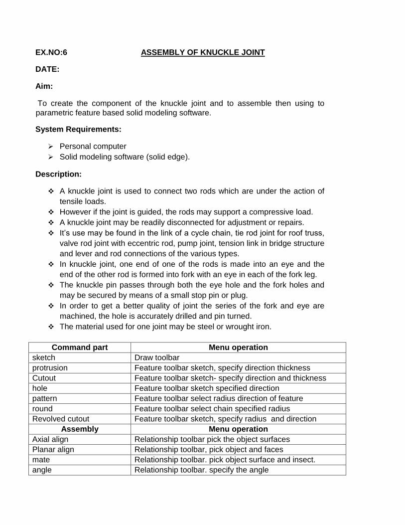
EX.NO:6 ASSEMBLY OF KNUCKLE JOINT
DATE:
Aim:
To create the component of the knuckle joint and to assemble then using to
parametric feature based solid modeling software.
System Requirements:
Personal computer
Solid modeling software (solid edge).
Description:
A knuckle joint is used to connect two rods which are under the action of
tensile loads.
However if the joint is guided, the rods may support a compressive load.
A knuckle joint may be readily disconnected for adjustment or repairs.
It’s use may be found in the link of a cycle chain, tie rod joint for roof truss,
valve rod joint with eccentric rod, pump joint, tension link in bridge structure
and lever and rod connections of the various types.
In knuckle joint, one end of one of the rods is made into an eye and the
end of the other rod is formed into fork with an eye in each of the fork leg.
The knuckle pin passes through both the eye hole and the fork holes and
may be secured by means of a small stop pin or plug.
In order to get a better quality of joint the series of the fork and eye are
machined, the hole is accurately drilled and pin turned.
The material used for one joint may be steel or wrought iron.
Command part Menu operation
sketch Draw toolbar
protrusion Feature toolbar sketch, specify direction thickness
Cutout Feature toolbar sketch- specify direction and thickness
hole Feature toolbar sketch specified direction
pattern Feature toolbar select radius direction of feature
round Feature toolbar select chain specified radius
Revolved cutout Feature toolbar sketch, specify radius and direction
Assembly Menu operation
Axial align Relationship toolbar pick the object surfaces
Planar align Relationship toolbar, pick object and faces
mate Relationship toolbar. pick object surface and insect.
angle Relationship toolbar. specify the angle

PROCEDURE
1. Identify various parts to be created.
2. First enter into part environment and create the main part and create the main part of the
assembly. 3. First identify whether the main part or the first to be created by protrusion or by
revolution. 4. Select the sketch tool and then select the coincidental plane option and select any one of the
standard 3 planes (i.e. front, right &top). 5. Create the cross-section profile as a closed one using the 2D commands available after
completing the sketch, click open or return button and then click finish button. 6. For creating other parts, select sketch both parallel plane option or plane by 3points option
and then select the required plane. 7. Construct the full cross section for portion and construct the half of the cross section and an
axis line for revolution. 8. Do the protrusions by using protrusion command and the revolution by revolved
protrusion command. 9. For constructing holes and cutout, used hole command and cutout command.
10. If we use hole command, change the diameter of the hole by using modify menu, resize
hole option. 11. Use revolved cutout command whenever needed.
12. Use the distance between option to maintain accurate distance between one edge and other
edge or between one edge and to center the hole. 13. After constructing each part save it as a separate part file with extrusion* par.
14. Enter into assembly environment.
15. Assembly the various parts construct parts construct using the various assembly
constrains available (planer, design, mate, axial align, connect etc). 16. After finishing assembly, check whether the various parts have been connected
properly or not by rotating the view. 17. Save the assembly as a file with extrusion*asm.
VIVA-VOCE QUESTIONS
1. What is knuckle joint?
2. What are the types of knuckle joint?
3. What are the parts of knuckle joint?

4. What are the applications of knuckle joint?
5. What are advantages of knuckle joint?
RESULT
Thus the 3D assembly of the knuckle joint has been created on the software solid edge with
accurate dimension and withal respects.
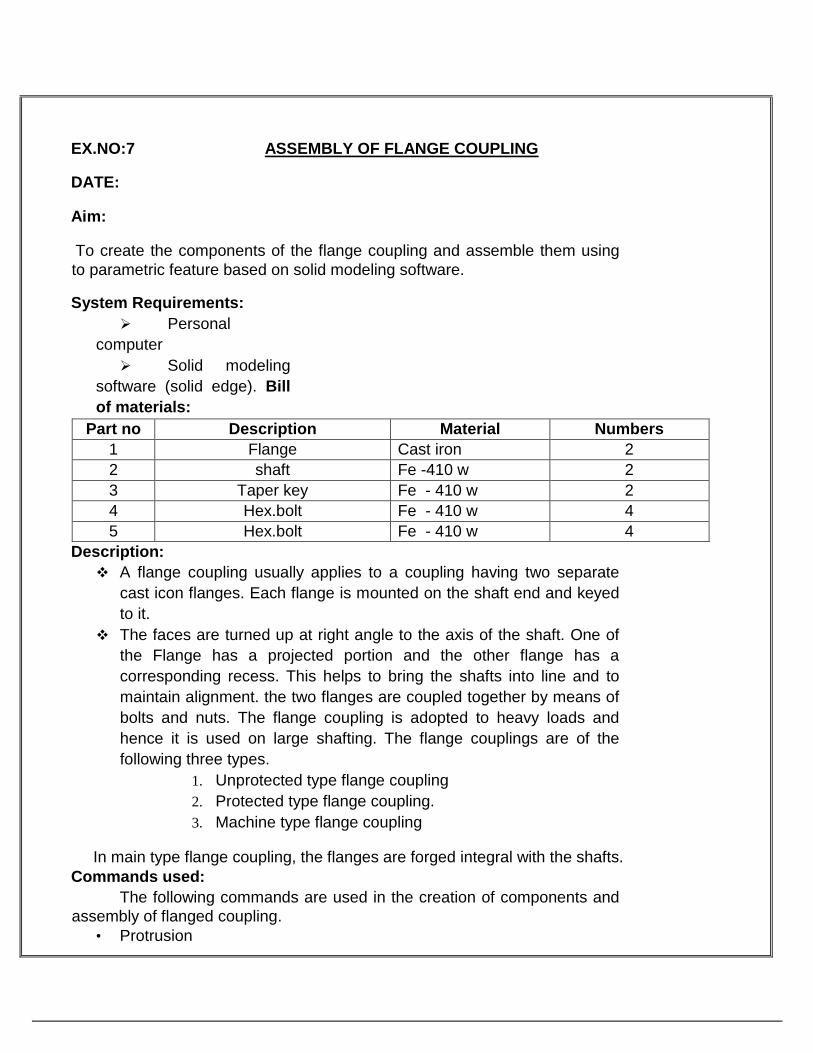
EX.NO:7 ASSEMBLY OF FLANGE COUPLING
DATE:
Aim:
To create the components of the flange coupling and assemble them using
to parametric feature based on solid modeling software.
System Requirements:
Personal
computer
Solid modeling
software (solid edge). Bill
of materials:
Part no Description Material Numbers
1 Flange Cast iron 2
2 shaft Fe -410 w 2
3 Taper key Fe - 410 w 2
4 Hex.bolt Fe - 410 w 4
5 Hex.bolt Fe - 410 w 4
Description:
A flange coupling usually applies to a coupling having two separate
cast icon flanges. Each flange is mounted on the shaft end and keyed
to it.
The faces are turned up at right angle to the axis of the shaft. One of
the Flange has a projected portion and the other flange has a
corresponding recess. This helps to bring the shafts into line and to
maintain alignment. the two flanges are coupled together by means of
bolts and nuts. The flange coupling is adopted to heavy loads and
hence it is used on large shafting. The flange couplings are of the
following three types.
1. Unprotected type flange coupling
2. Protected type flange coupling.
3. Machine type flange coupling
In main type flange coupling, the flanges are forged integral with the shafts.
Commands used:
The following commands are used in the creation of components and
assembly of flanged coupling.
• Protrusion

• Coincident plane
• Cutout
• Revolved protrusion
• Revolved cutout
• Mate
• Axial align
• Panel align
• Trim
PROCEDURE
1. Identify various parts to be created.
2. First enter into part environment and create the main part and create the main part of
the assembly. 3. First identify whether the main part or the first to be created by protrusion or by
revolution. 4. Select the sketch tool and then select the coincidental plane option and select any one
of the standard 3 planes (i.e. front, right &top). 5. Create the cross-section profile as a closed one using the 2D commands available after
completing the sketch, click open or return button and then click finish button. 6. For creating other parts, select sketch both parallel plane option or plane by 3points
option and then select the required plane. 7. Construct the full cross section for portion and construct the half of the cross section
and an axis line for revolution. 8. Do the protrusions by using protrusion command and the revolution by revolved
protrusion command. 9. For constructing holes and cutout, used hole command and cutout command.
10. If we use hole command, change the diameter of the hole by using modify menu,
resize hole option.


VIVA-VOCE QUESTIONS
1. What is coupling?
2. What are the types of couplings?
3. What is protected type flange coupling?
4. What is use of protected type flange coupling?
5. What is the specification of protected type flange coupling?
6. What are the advantages of protected type flange coupling?
RESULT
Thus the 3D assembly of the flange coupling has been created on the software solid edge with
accurate dimension and withal respects.

EX.NO:8 ASSEMBLY OF PLUMMER BLOCK
DATE:
Aim:
To model and assemble the Plummer block as per dimension given and also
convert the 3D model into different views with bill of materials..
System Requirements:
Personal computer
Solid modeling software (solid edge).
Bill of materials:
Part no Description Material Numbers
1 A cap Cast iron 1
2 Spilt bushes Brass 2
3 Square head bolts Fe 410 w 2
4 Hexagonal nuts Fe 410 w 2
5 Shaft Fe 410 w 1
6 Body Cast iron 1
Description:
When a long shaft is to be supported at intermediate points, bushed
bearing are not used due to their limitations. In such cases plummer blocks
are used.
In the plummer block bearing, the body is split horizontally along or near
axis of the shaft. This will enable to overcome the disadvantage of the
bushed bearings.
The bottom of the body is relieved leaving a narrow machined strip all
rounds and it reduces the extent of preparation and leveling of the bearing
area relatively.
Split bush is fitted in the body, the projecting snug of the split bush fits into
the corresponding hole drilled in the body. This prevents the rotation of the
bushes along with the shaft and axial movement of the split bushes are
prevented by collars.
After assembling a small clearance will be left between cap and the body.
This clearance enables to provide the necessary clamping grip.
Commands used:
The following commands are used in the creation of components and
assembly of flanged coupling.
• Protrusion
• Coincident plane

• Cutout
• Round
• chamfer
• Mate
• Axial align
• Panel align
• Trim
PROCEDURE 1. Identify various parts to be created.
2. First enter into part environment and create the main part and create the main part of the
assembly. 3. First identify whether the main part or the first to be created by protrusion or by
revolution. 4. Select the sketch tool and then select the coincidental plane option and select any one of the
standard 3 planes (i.e. front, right &top). 5. Create the cross-section profile as a closed one using the 2D commands available after
completing the sketch, click open or return button and then click finish button. 6. For creating other parts, select sketch both parallel plane option or plane by 3points option
and then select the required plane. 7. Construct the full cross section for portion and construct the half of the cross section and an
axis line for revolution. 8. Do the protrusions by using protrusion command and the revolution by revolved
protrusion command. 9. For constructing holes and cutout, used hole command and cutout command.
10. If we use hole command, change the diameter of the hole by using modify menu, resize
hole option.
11. Use revolved cutout command whenever needed.
12. Use the distance between option to maintain accurate distance between one edge and other
edge or between one edge and to center the hole. 13. After constructing each part save it as a separate part file with extrusion* par.
14. Enter into assembly environment.
15. Assembly the various parts construct parts construct using the various assembly
constrains available (planer, design, mate, axial align, connect etc). 16. After finishing assembly, check whether the various parts have been connected
properly or not by rotating the view. 17. Save the assembly as a file with extrusion*asm.

VIVA-VOCE QUESTIONS
1. What is Plummer block?
2. What are the types of Plummer block?
3. What is the use of Plummer block?
4. What is specification of Plummer block?
5. What are advantages of Plummer block?

RESULT
Thus the 3D assembly of the Plummer block has been created on the software solid edge with
accurate dimension and withal respects.

EX.NO:9 ASSEMBLY OF CROSSS HEAD DATE:
AIM To create the crosss headassembly as a 3Dsolid model.
HARDWARE REQUIRED
1. CPU with pentium IV processor.
2. A colour monitor with highest 32 bit colour display and with screen resolution 1024 by
768 pixels. 3. A scroll mouse.
SOFTWARE REQUIRED
1. Windows XP operating system
2. SOLID EDGE 19.0
PROCEDURE
1. Identify various parts to be created.
2. First enter into part environment and create the main part and create the main part of the
assembly. 3. First identify whether the main part or the first to be created by protrusion or by
revolution. 4. Select the sketch tool and then select the coincidental plane option and select any one of the
standard 3 planes (i.e. front, right &top). 5. Create the cross-section profile as a closed one using the 2D commands available after
completing the sketch, click open or return button and then click finish button. 6. For creating other parts, select sketch both parallel plane option or plane by 3points option
and then select the required plane. 7. Construct the full cross section for portion and construct the half of the cross section and an
axis line for revolution. 8. Do the protrusions by using protrusion command and the revolution by revolved
protrusion command. 9. For constructing holes and cutout, used hole command and cutout command.
10. If we use hole command, change the diameter of the hole by using modify menu, resize
hole option.
11. Use revolved cutout command whenever needed.

12. Use the distance between option to maintain accurate distance between one edge and other
edge or between one edge and to center the hole. 13. After constructing each part save it as a separate part file with extrusion* par.
14. Enter into assembly environment.
15. Assembly the various parts construct parts construct using the various assembly
constrains available (planer, design, mate, axial align, connect etc). 16. After finishing assembly, check whether the various parts have been connected
properly or not by rotating the view. 17. Save the assembly as a file with extrusion*asm.
VIVA-VOCE QUESTIONS
1. What is crosss head?
2. What are the types of crosss head?
3. What are the parts of crosss head?
4. What are the applications of crosss head?
5. What are advantages of crosss head?
RESULT
Thus the 3D assembly of the crosss head has been created on the software solid edge with
accurate dimension and withal respects.

EX.NO:10 ASSEMBLY OF SCREW JACK
DATE:
Aim:
To model and assemble the components of screw jack as per the given
dimensions and to covert the 3D views with bill of materials.
System requirement:
Personal computer
Solid modeling software (solid edge).
Bill of materials:
Part no Description Material Numbers
1 Body Cast iron 1
2 Nut Gun metal 1
3 Screw spindle Fe - 410 w 1
4 Cup Cast Steel 1
5 Washer special Fe - 410 w 1
6 Counter shunk screw Fe - 410 w 1
7 Tommy bar Fe - 410 w 1
Commands used:
Command part Menu operation
sketch Draw toolbar
protrusion Feature- toolbar sketch-specify direction thickness
Cutout Feature -toolbar -sketch- specify direction and thickness
round Feature -toolbar -select chain -specified radius
chamfer Feature – tool bar –select chain –specify length
offset Feature – select thickness
extend Feature – select the line to extend it
Assembly Menu operation
Axial align Relationship -toolbar -pick the object surfaces
mate Relationship toolbar. pick object surface and insect.
Procedure:
1. From the main menu of solid work, select the drawing option.
2. Select the drawing sheet format as A4 landscape.
3. Using the model view manager browse the document to be open

4. Click the view orientation from the model view manager and place the
drawing view in the proper place in the sheet.
Model the different parts of screw jack by using sketch, protrusion, extend command.
PROCEDURE
1. Identify various parts to be created.
2. First enter into part environment and create the main part and create the main part of the
assembly. 3. First identify whether the main part or the first to be created by protrusion or by
revolution. 4. Select the sketch tool and then select the coincidental plane option and select any one of the
standard 3 planes (i.e. front, right &top). 5. Create the cross-section profile as a closed one using the 2D commands available after
completing the sketch, click open or return button and then click finish button. 6. For creating other parts, select sketch both parallel plane option or plane by 3points option
and then select the required plane. 7. Construct the full cross section for portion and construct the half of the cross section and an
axis line for revolution. 8. Do the protrusions by using protrusion command and the revolution by revolved
protrusion command. 9. For constructing holes and cutout, used hole command and cutout command.
10. If we use hole command, change the diameter of the hole by using modify menu, resize
hole option.
11. Use revolved cutout command whenever needed.
12. Use the distance between option to maintain accurate distance between one edge and other
edge or between one edge and to center the hole. 13. After constructing each part save it as a separate part file with extrusion* par.
14. Enter into assembly environment.
15. Assembly the various parts construct parts construct using the various assembly
constrains available (planer, design, mate, axial align, connect etc). 16. After finishing assembly, check whether the various parts have been connected
properly or not by rotating the view. 17. Save the assembly as a file with extrusion*asm.

RESULT
Thus the 3D assembly of the screw jack has been created on the software solid edge with
accurate dimension and withal respects.

EX.NO:11 ASSEMBLY OF CONNECTING ROD DATE:
AIM To create the connecting rod assembly as a 3D solid model.
HARDWARE REQUIRED
1. CPU with pentium IV processor.
2. A colour monitor with highest 32 bit colour display and with screen resolution 1024 by
768 pixels. 3. A scroll mouse.
SOFTWARE REQUIRED
1. Windows XP operating system
2. SOLID EDGE 19.0
PROCEDURE
1. Identify various parts to be created.
2. First enter into part environment and create the main part and create the main part of the
assembly. 3. First identify whether the main part or the first to be created by protrusion or by
revolution. 4. Select the sketch tool and then select the coincidental plane option and select any one of the
standard 3 planes (i.e. front, right &top). 5. Create the cross-section profile as a closed one using the 2D commands available after
completing the sketch, click open or return button and then click finish button. 6. For creating other parts, select sketch both parallel plane option or plane by 3points option
and then select the required plane. 7. Construct the full cross section for portion and construct the half of the cross section and an
axis line for revolution. 8. Do the protrusions by using protrusion command and the revolution by revolved
protrusion command. 9. For constructing holes and cutout, used hole command and cutout command.
10. If we use hole command, change the diameter of the hole by using modify menu, resize
hole option.
11. Use revolved cutout command whenever needed.

12. Use the distance between option to maintain accurate distance between one edge and other
edge or between one edge and to center the hole. 13. After constructing each part save it as a separate part file with extrusion* par.
14. Enter into assembly environment.
15. Assembly the various parts construct parts construct using the various assembly
constrains available (planer, design, mate, axial align, connect etc). 16. After finishing assembly, check whether the various parts have been connected
properly or not by rotating the view. 17. Save the assembly as a file with extrusion*asm.
VIVA-VOCE QUESTIONS
1. What is connecting rod?
2. What are the types of connecting rod?
3. What are the parts of connecting rod?
4. What are the applications of connecting rod?
5. What are advantages of connecting rod?

RESULT Thus the 3D assembly of the connecting rod has been created on the software solid edge with
accurate dimension and withal respects.
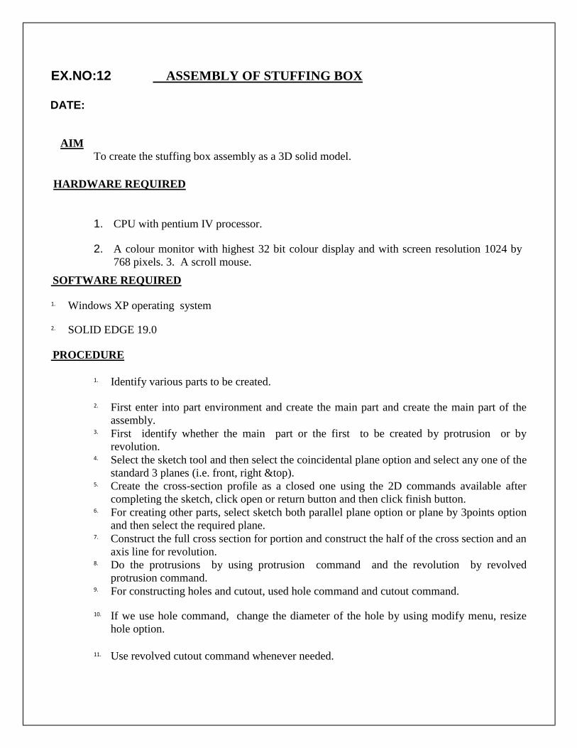
EX.NO:12 ASSEMBLY OF STUFFING BOX
DATE:
AIM To create the stuffing box assembly as a 3D solid model.
HARDWARE REQUIRED
1. CPU with pentium IV processor.
2. A colour monitor with highest 32 bit colour display and with screen resolution 1024 by
768 pixels. 3. A scroll mouse.
SOFTWARE REQUIRED
1. Windows XP operating system
2. SOLID EDGE 19.0
PROCEDURE
1. Identify various parts to be created.
2. First enter into part environment and create the main part and create the main part of the
assembly. 3. First identify whether the main part or the first to be created by protrusion or by
revolution. 4. Select the sketch tool and then select the coincidental plane option and select any one of the
standard 3 planes (i.e. front, right &top). 5. Create the cross-section profile as a closed one using the 2D commands available after
completing the sketch, click open or return button and then click finish button. 6. For creating other parts, select sketch both parallel plane option or plane by 3points option
and then select the required plane. 7. Construct the full cross section for portion and construct the half of the cross section and an
axis line for revolution. 8. Do the protrusions by using protrusion command and the revolution by revolved
protrusion command. 9. For constructing holes and cutout, used hole command and cutout command.
10. If we use hole command, change the diameter of the hole by using modify menu, resize
hole option.
11. Use revolved cutout command whenever needed.

12. Use the distance between option to maintain accurate distance between one edge and other
edge or between one edge and to center the hole. 13. After constructing each part save it as a separate part file with extrusion* par.
14. Enter into assembly environment.
15. Assembly the various parts construct parts construct using the various assembly
constrains available (planer, design, mate, axial align, connect etc). 16. After finishing assembly, check whether the various parts have been connected
properly or not by rotating the view. 17. Save the assembly as a file with extrusion*asm.
VIVA-VOCE QUESTIONS
1. What is stuffing box?
2. What are the parts of stuffing box?
3. What are the applications of stuffing box?
4. What are advantages of stuffing box?
5. What is the specification of stuffing box?

RESULT
Thus the 3D assembly of the stuffing box has been created on the software solid edge with
accurate dimension and withal respects.

EX.NO:13 ASSEMBLY OF MACHINE VICE
DATE:
AIM To create the machine vice assembly as a 3D solid model.
HARDWARE REQUIRED
1. CPU with pentium IV processor.
2. A colour monitor with highest 32 bit colour display and with screen resolution 1024 by
768 pixels. 3. A scroll mouse.
SOFTWARE REQUIRED
1. Windows XP operating system
2. SOLID EDGE 19.0
PROCEDURE
1. Identify various parts to be created.
2. First enter into part environment and create the main part and create the main part of the
assembly. 3. First identify whether the main part or the first to be created by protrusion or by
revolution. 4. Select the sketch tool and then select the coincidental plane option and select any one of the
standard 3 planes (i.e. front, right &top). 5. Create the cross-section profile as a closed one using the 2D commands available after
completing the sketch, click open or return button and then click finish button. 6. For creating other parts, select sketch both parallel plane option or plane by 3points option
and then select the required plane. 7. Construct the full cross section for portion and construct the half of the cross section and an
axis line for revolution. 8. Do the protrusions by using protrusion command and the revolution by revolved
protrusion command. 9. For constructing holes and cutout, used hole command and cutout command.
10. If we use hole command, change the diameter of the hole by using modify menu, resize
hole option.
11. Use revolved cutout command whenever needed.

12. Use the distance between option to maintain accurate distance between one edge and other
edge or between one edge and to center the hole. 13. After constructing each part save it as a separate part file with extrusion* par.
14. Enter into assembly environment.
15. Assembly the various parts construct parts construct using the various assembly
constrains available (planer, design, mate, axial align, connect etc). 16. After finishing assembly, check whether the various parts have been connected
properly or not by rotating the view. 17. Save the assembly as a file with extrusion*asm.
VIVA-VOCE QUESTIONS
1. What is vice?
2. What is machine vice?
3. What are the parts of machine vice?
4. What are the applications of machine vice?
5. What are advantages of machine vice?

RESULT
Thus the 3D assembly of the machine vice has been created on the software solid edge with
accurate dimension and withal respects.
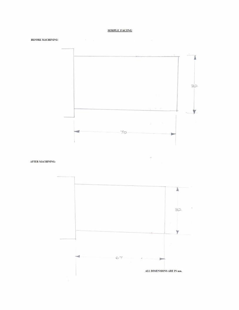
CAM – EXERCISES
EX.NO:1 STUDY OF “G” CODES AND “M” CODES
Aim:
To study the “G” codes and “M” codes for the CNC milling machine.
Programming codes:
Codes are model and do not have to be repeated in
every sequence line. All dimensions are entered as
decimals.
G –codes for turning machine:
MTAB INDIA PVT LTD
G- To define tool movement for preparatory function.
G OO > Rapid movement
G O1 > Linear movement with feed rate
G 02 > Circular interpretation clockwise with feed rate
G 03 > Circular interpretation counterclockwise with feed rate
G 04 > Dwell time in
seconds G 17 > XY
plane
G 18 > XZ plane
G 19 > YZ plane
G 20 > Inch mode input (in”)
G 21 > multi mode input (mm)
G 28 > return to reference point (home position)
G 40 > tool nose radius compensation cancel
G 41 > tool nose radius compensation left
G 42 > tool nose radius compensation right
G 70 > finishing cycle
G 71 > multiple turning cycle
G 72 > multiple facing cycle
G 74 > deck drilling cycle in z axis
G 75 > grooving cycle in z axis
G 76 > thread cutting cycle
G 90 > turning cycle
G 92 > thread
cutting cycle G 94
> facing cycle

G 98 > feed per minute
G 99 > feed per revolution
M- Codes / Miscellaneous codes:
M 00 > program stop
M 01 > optional stop
M 02 > program end
M 03 > spindle forward (cw)
M 04 > spindle reverse ( ccw)
M 05 > spindle stop
M 06 > tool change
M 08 > coolant ON
M 09 > coolant OFF
M 10 > chuck open
M 11 > chuck close
M 30 > program stop and restart
M 98 > sub program call
M 99 > sub program exit
G- CODES FOR MILLING MACHINES:
HYTECH CNC MACHINE,PUNE
G 00 > point to point rapid positioning
G 01 > linear interpretation
G 02 > Circular interpretation arc clockwise
G 03 > Circular interpretation arc counterclockwise
G 04 > Dwell time in seconds
G 12 > circular pocketing clockwise
G 13 > circular pocketing anticlockwise
G 15 > polar coordinate system OFF
G 16 > polar coordinate system ON G 17 > XY plane selection for arc movement G 18 > XZ plane selection for arc movement G 19 > YZ plane selection for arc movement
G 20 > selecting inch mode input
G 21 > selecting metric mode input
G 40 > cutter compensation/offset,cancel
G 41 > cutter radius compensation / offset-left G 42 >

cutter radius compensation / offset-right G 43 > tool length compensation -positive G 44 > tool length compensation -negative G 49 > tool length compensation -cancel G 50 > scaling mode cancel (OFF) G 51 > scaling mode ON G 54 > shift of
coordinate G 55
> shift of
coordinate
G 56 > shift of coordinate
G 57 > shift of coordinate
G 58 > shift of coordinate
G 59 > shift of coordinate
G 68 > coordinate rotation system ON
G 69 > coordinate rotation
system ON G 70 > Inch
programming
G 71 > metric programming
G 80 > drilling cycle
G 81 > fixed cycle no 1 drill, spot drill
G 82 > fixed cycle no 2 drill, counter bore
G 83 > fixed cycle no 3 drill, deep hole
G 84 > tapping cycle
G 85 > fixed cycle no 4 drill, bore
G 86 > boring cycle
G 87 > back boring cycle
G 88 > boring cycle
G 89 > boring cycle
G 90 > absolute dimension input
G 91 > incremental dimension input
G 94 > feed rate selection per min
G 95 > feed rate selection per minute
G 98, 99 > tool return position
G 28 > return to reference point (home position)
G 40 > tool nose radius compensation cancel
G 41 > tool nose radius compensation left
G 42 > tool nose radius compensation right
G 70 > finishing cycle
G 71 > multiple turning cycle

G 72 > multiple facing cycle
G 74 > peck drilling cycle in z axis
G 75 > grooving cycle in z axis
G 76 > thread cutting cycle
G 90 > turning cycle
G 92 > thread cutting cycle
G 94 >
facing cycle
G 98 > feed
per minute
G 99 > feed per revolution
M- Codes / Miscellaneous codes:
M 00 > program stop
M 01 > optional program stop
M 02 > program end
M 03 > spindle motor ON and forward direction (cw)
M 04 > spindle motor ON and reverse direction ( ccw)
M 05 > spindle stop
M 06 > automatic tool
change M 08 >
coolant pump motor
ON
M 09 > coolant pump motor OFF
M 21 > mirror image along x axis
M 22 > mirror image along y axis
M 23 > mirror image along z axis
M 30 > program stop and restart
M 98 > sub program call
M 99 > sub program exit
RESULT
Thus the “G” codes and “M” codes for the CNC milling machines were studied.


EX.NO:2 CNC-MILLING RECTANGULAR POCKETING
DATE:
Aim:
To perform a rectangular milling operation by using CNC milling programming codes.
Apparatus required:
CNC machine
Personal computer
CNC software Program:
M 03 S 1500
(Stock /block 100,100, 10, -4, -4, -7)
(tool /mill 10, 0, 30, 0)
(color 0, 255, 0)
G21 G98
G00 X0 Y0 Z5
G00 X10 Y10 Z5 F120
G01 X60 Y10 Z-3 F120
G01 X60 Y60 Z-3 F120
G01 X10 Y60 Z-3 F120
G01 X10 Y10 Z-3 F120
G00 X0 Y0 Z5
M05 M30
RESULT:
Thus the rectangular milling operations by using CNC milling programming
codes were performed.


EX.NO:3 CNC-MILLING CIRCULAR POCKETING
DATE:
Aim:
To write a manual part program for performing a circular pocketing milling
operation by using CNC milling programming codes.
Apparatus required:
CNC machine
Personal computer
CNC software
Work piece (100 x100 x 10 mm) Program:
(Stock /block 100,100, 10, 15, 10)
(tool /mill 5, 0, 50, 0)
(color 255,255, 255)
G21 G98
M05 S1500
G00 X0 Y0 Z5
G00 X50 Y50 Z5
G01 X50 Y50 Z-2 F50
G02 I5 F50
G02 I9 F50
G02 I12 F50
G00 X50 Y50 Z5
G00 X0 Y0 Z5
M05
M30
RESULT:
Thus the circular milling operations by using CNC milling programming codes were
performed.


EX.NO:4 CNC LATHE-SIMPLE TURNING
DATE:
Aim:
To perform the simple turning operation by using CNC programming codes.
Apparatus required:
CNC machine
Personal computer
CNC software
Cutting tool
Work piece Program:
Billet X32 Z70
G21 G98
G28 U0 W0
M06 T02
M03 S1000
G00 X32 Z3
G90 X31 Z-28 F100
X30
X29
X28
G28 U0 W0
M05
M30
RESULT:
Thus the simple turning operation was performed by using CNC Lathe programming codes.

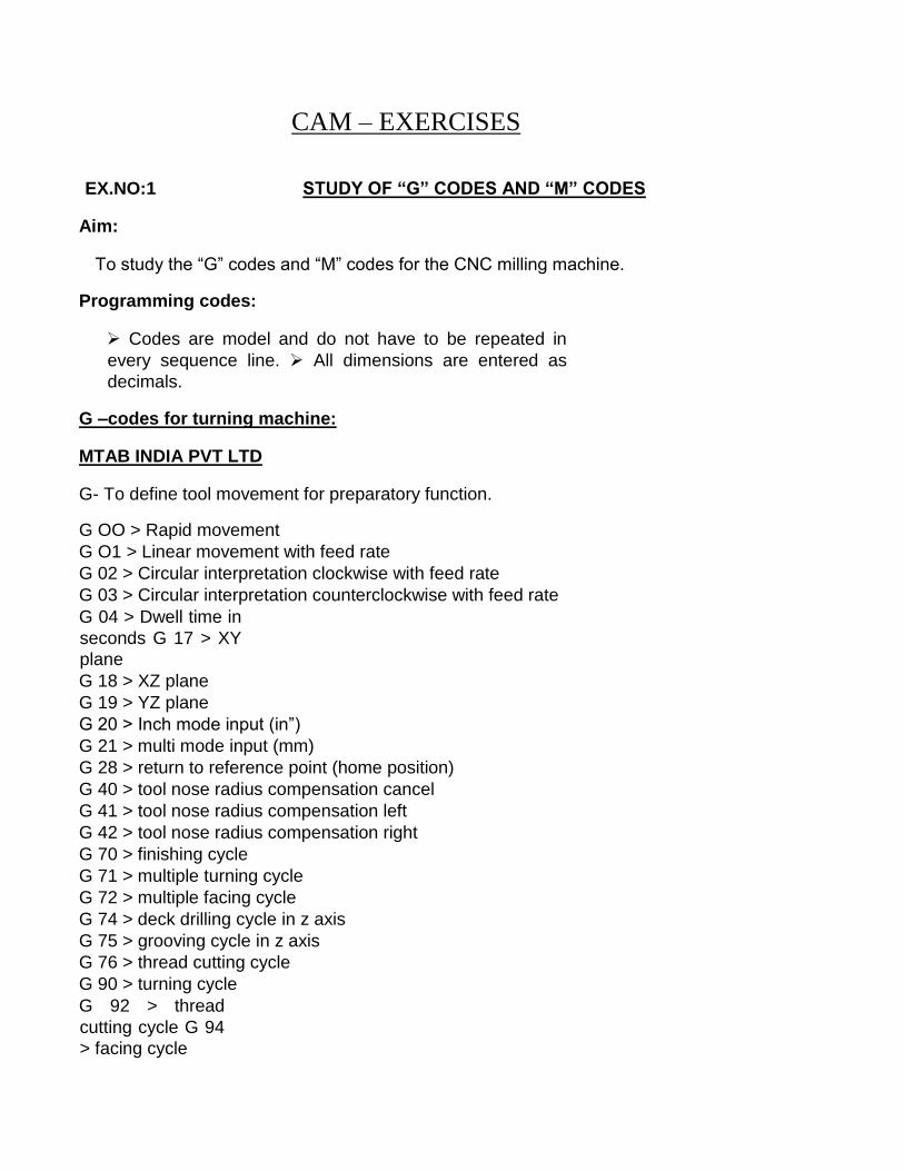
EX.NO:5 CNC LATHE-STEP TURNING
DATE:
Aim:
To perform the step turning operation by using CNC programming codes.
Apparatus required:
CNC machine
Personal computer
CNC software
Cutting tool
Work piece Program:
Billet X32 Z70
G21 G98
G28 U0 W0
M06 T01
M03 S1500
G00 X32 Z5
G90 X31 z-30
X30 Z-25
X28 Z-20
X24 Z-15
G28 U0 W0
M05
M30
RESULT:
Thus the step turning operation was performed by using CNC Lathe programming codes.

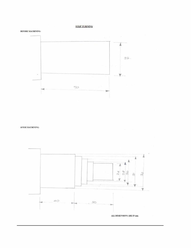
EX.NO:6 CNC LATHE –SIMPLE FACING
DATE:
Aim:
To perform a simple facing operation by using CNC programming codes.
Apparatus required:
CNC machine
Personal computer
CNC software
Cutting tool
Work piece Program:
Billet X32 Z70
G21 G98
G28 U0 W0
M06 T01
M03 S1500
G00 X32 Z0
G94 X0 Z-1 F100
Z-2
Z-3
G28 U0 W0
M05
M30
RESULT:
Thus the Simple facing operation was performed by using CNC Lathe programming codes.


EX.NO:7 CNC LATHE –RIGHT HAND TAPER TURNING
DATE:
Aim:
To perform the right hand taper turning operation by using CNC programming codes.
Apparatus required:
CNC machine
Personal computer
CNC software
Cutting tool
Work piece Program:
Billet X32 Z70
G21 G98
G28 U0 W0
M06 T01
M03 S1500
G00 X32 Z5
G90 X30 Z-30 R-1 F50
R-2
R-3
G28 U0 W0
M05
M30
RESULT:
Thus the right hand taper turning operation was performed by using CNC
Lathe programming codes.


EX.NO:8 CNC LATHE –LEFT HAND TAPER TURNING
DATE:
Aim:
To perform the left hand taper turning operation by using CNC programming codes.
Apparatus required:
CNC machine
Personal computer
CNC software
Cutting tool
Work piece Program:
Billet X32 Z70
G21 G98
G28 U0 W0
M06 T01
M03 S1500
G00 X32 Z5
G90 X30 Z-30 R-1 F50
X28 R2
X26 R3
G28 U0 W0
M05
M30
RESULT:
Thus the left hand taper turning operation was performed by using CNC
Lathe programming codes.


EX.NO:9 CNC LATHE –THREAD CUTTING OPERATION
DATE:
Aim:
To perform thread cutting operation by using CNC programming codes.
Apparatus required:
CNC machine
Personal computer
CNC software
Cutting tool
Work piece Program:
Billet X32 Z70
G21 G99
G28 U0 W0
M06 T02
M03 S1500
G00 X32 Z5
G94 X31 Z45 F1.5
X30.5
X30
G00 X29.3 Z2
G76 P1 Q12 R0.7 F0.5
G76 X28.05 Z40 P12 Q12 F0.5
X28.6 R1.4
X28 R1.95
G28 U0 W0
M05
M30
RESULT:
Thus the thread cutting operation was performed by using CNC Lathe programming codes.