solid edge v19
DESCRIPTION
Solid edge v19 tutorials which helps us for learning the solid modeling under this softTRANSCRIPT
Table of Contents
Dedication iiiPreface xv
Introduction to Solid Edge 1-2Solid Edge Environments 1-5System Requirements for Solid Edge V19 1-6Important Terms and Definitions 1-7Getting Started with Solid Edge V19 1-10User Interface of Solid Edge 1-10Additional Design Tools 1-14Color Scheme in this Textbook 1-16Units for Dimensions 1-16Automatic Saving Option 1-16Self-Evaluation Test 1-18
The Sketching Environment 2-2Starting the Part Environment in Solid Edge 2-3Starting a New Part Document Using the New Dialog Box 2-4
Invoking the Sketching Environment 2-6The Drawing Display Tools 2-7
Zooming to an Area 2-7Dynamic Zooming 2-8Fitting all Entities in the Current Display 2-8Panning Drawings 2-8Restoring the Original Orientation of the Sketching Plane 2-9
Sketching Tools 2-9Drawing Lines 2-9Drawing Circles 2-12Drawing Ellipses 2-13Drawing Arcs 2-14Drawing Rectangles 2-15Drawing Curves 2-16Converting Sketched Entities into Curves 2-17Filleting Sketched Entities 2-17Chamfering Sketched Entities 2-18
Selecting the Sketched Entities 2-19
Chapter 2: Drawing Sketches for Solid Models
Chapter 1: Introduction to Solid Edge

vi Solid Edge for Designers (Eval Copy SE 11/06)
Deleting the Sketched Entities 2-20Tutorial 1 2-20Tutorial 2 2-26Tutorial 3 2-31Self-Evaluation Test 2-35Review Questions 2-36Exercise 1 2-37Exercise 2 2-37
Geometric Relationships 3-2Connect Relationship 3-2Concentric Relationship 3-3Horizontal/Vertical Relationship 3-3Collinear Relationship 3-4Parallel Relationship 3-4Perpendicular Relationship 3-4Lock Relationship 3-4Rigid Set Relationship 3-4Tangent Relationship 3-5Equal Relationship 3-5Symmetric Relationship 3-5Setting the Symmetry Axis 3-6Controlling the Display of Relationship Handles 3-6
Conflicts in Relationships 3-7Deleting Relationships 3-7Dimensioning the Sketched Entities 3-7
Adding Linear Dimensions 3-8Adding Aligned Dimensions 3-10Adding Angular Dimensions 3-11Adding Diameter Dimensions 3-12Adding Radial Dimensions 3-13Adding Symmetric Diameter Dimensions 3-14Adding Coordinate Dimensions 3-15Adding Angular Coordinate Dimensions 3-16
Adding Automatic Dimensions 3-16Understanding the Concept of Fully Constrained Sketches 3-18Measuring Sketched Entities 3-18
Measuring Distances 3-18Measuring the Total Length of a Closed Loop or an Open Sketch 3-19Measuring Area 3-19Calculating the Area Properties 3-20
Tutorial 1 3-21Tutorial 2 3-28Tutorial 3 3-33
Chapter 3: Adding Relationships and Dimensions to Sketches
Table of Contents vii
Self-Evaluation Test 3-37Review Questions 3-38Exercise 1 3-39Exercise 2 3-39
Editing Sketches 4-2Trimming the Sketched Entities 4-2Extending the Sketched Entities 4-2Trimming/Extending Entities to a Corner 4-3Creating Offset Copies 4-3Creating Symmetric Offset Copies 4-4Moving/Copying the Sketched Entities 4-7Rotating the Sketched Entities 4-8Mirroring the Sketched Entities 4-8Scaling the Sketched Entities 4-9Stretching the Sketched Entities 4-10Editing the Sketched Entities by Dragging 4-10
Writing Text in the Sketching Environment 4-12Inserting Images in the Sketches 4-13Converting Sketches into Base Features 4-15Creating Base Features by Protrusion 4-15Creating Base Features Using the Revolved Protrusion 4-20Rotating the View of a Model in 3D Space 4-22Restoring Standard Views 4-23Setting Display Modes 4-23
Shaded with Visible Edges 4-23Shaded 4-23Visible and Hidden Edges 4-23Visible Edges 4-24Drop Shadow 4-24
Improving the Display Quality of the Model 4-24Tutorial 1 4-24Tutorial 2 4-30Tutorial 3 4-34Self-Evaluation Test 4-36Review Questions 4-37Exercise 1 4-38Exercise 2 4-38
Additional Sketching and Reference Planes 5-2Local Reference Planes 5-3Global Reference Planes 5-3
Creating Reference Planes 5-4
Chapter 4: Editing, Extruding, and Revolving the Sketches
Chapter 5: Working with Additional Reference Planes

viii Solid Edge for Designers (Eval Copy SE 11/06)
Creating a Coincident Plane 5-4Creating a Parallel Plane 5-5Creating an Angled Plane 5-6Creating a Perpendicular Plane 5-7Creating a Coincident Plane by Axis 5-8Creating a Plane Normal to an Edge or a Sketched Curve 5-8Creating a Plane Using Three Points 5-9Displaying the Reference Axes 5-10
Understanding Coordinate Systems 5-11Creating a Coordinate System 5-11
Using the Other Options of the Protrusion Tool 5-13Creating Cutout Features 5-21
Creating Extruded Cutouts 5-21Creating Revolved Cutouts 5-23
Including the Edges of the Existing Features in the Sketch 5-23Advanced Drawing Display Tools 5-25
Creating User-defined Named Views 5-26Using Common Views 5-26Tutorial 1 5-27Tutorial 2 5-32Tutorial 3 5-39Self-Evaluation Test 5-45Review Questions 5-46Exercise 1 5-47Exercise 2 5-48
Advanced Modeling Tools 6-2Creating Holes 6-2Creating Rounds 6-9
Creating Constant Radius Round 6-10Creating Variable Radius Round 6-15
Creating Chamfers 6-16Creating Rectangular and Circular Patterns 6-18
Creating Rectangular Patterns 6-18Creating Circular Patterns 6-23
Creating the Pattern Along a Curve 6-25Mirroring Features and Bodies 6-29
Mirroring Selected Features 6-29Mirroring Bodies 6-30
Tutorial 1 6-31Tutorial 2 6-37Tutorial 3 6-45Self-Evaluation Test 6-50Review Questions 6-51Exercise 1 6-52
Chapter 6: Advanced Modeling Tools-I
Table of Contents ix
Exercise 2 6-53Exercise 3 6-53
Editing Features in a Model 7-2Suppressing Features 7-4Unsuppressing the Suppressed Features 7-5Deleting Features 7-6Copying and Pasting Features 7-6Rolling Back the Model to a Feature 7-7Assigning Color to a Part, Feature, or Face 7-8Playing Back the Construction of Features 7-8Checking the Physical Properties of a Model 7-9Modifying the Display of Construction Entities 7-10Tutorial 1 7-10Tutorial 2 7-16Tutorial 3 7-21Self-Evaluation Test 7-26Review Questions 7-26Exercise 1 7-27Exercise 2 7-27
Advanced Modeling Tools 8-2Creating Internal or External Threads 8-2Adding Drafts to the Model 8-4Adding Ribs to the Model 8-6Adding Thin Wall Features 8-10Adding Thin Wall to a Particular Region 8-12Adding a Lip to the Model 8-15Creating Web Networks 8-16Creating Vents 8-17Creating Mounting Bosses 8-22Reordering Features 8-26Tutorial 1 8-27Tutorial 2 8-33Tutorial 3 8-39Self-Evaluation Test 8-43Review Questions 8-44Exercise 1 8-45Exercise 2 8-46
Advanced Modeling Tools 9-2
Chapter 8: Advanced Modeling Tools-II
Chapter 9: Advanced Modeling Tools-III
Chapter 7: Editing Features

x Solid Edge for Designers (Eval Copy SE 11/06)
Creating Swept Protrusions 9-2Creating Swept Cutouts 9-9Creating Lofted Protrusions 9-9Creating Lofted Cutouts 9-16Creating Helical Protrusions 9-17Creating Normal Protrusions 9-23Creating Normal Cutouts 9-24Tutorial 1 9-24Tutorial 2 9-35Tutorial 3 9-45Self-Evaluation Test 9-53Review Questions 9-54Exercise 1 9-55Exercise 2 9-56
The Assembly Environment 10-2Setting up the Assembly Environment 10-2Types of Assembly Design Approaches 10-2
Creating the Bottom-Up Assembly 10-3Assembling the First Component in an Assembly 10-3Assembling the Second Component in an Assembly 10-4Adding Assembly Relationships 10-5
Creating the Top-Down Assembly 10-15Creating a Component in the Top-Down Assembly 10-15
Creating the Pattern of Components in an Assembly 10-17Creating a Reference Pattern 10-17
Creating the Material Removal Features in an Assembly 10-18Assembly Features 10-18Assembly-driven Part Features 10-18
Moving Individual Components 10-19Tutorial 1 10-21Tutorial 2 10-36Self-Evaluation Test 10-44Review Questions 10-45Exercise 1 10-46
Creating Subassemblies 11-2Editing Assembly Relationships 11-3
Modifying the Values 11-3Applying Additional Relationships 11-3Modifying Assembly Relationships 11-4
Editing Assembly Components 11-6Dispersing Subassemblies 11-6
Chapter 11: Assembly Modeling-II
Chapter 10: Assembly Modeling-I
Table of Contents xi
Replacing Components 11-7Simplifying Assemblies Using the Visibility Options 11-7
Hiding and Displaying the Components 11-8Changing the Transparency Conditions 11-8
Interference Detection in Assemblies 11-8Creating Exploded State of Assemblies 11-11
Changing the Distance Between the Components 11-15Repositioning the Parts 11-16Removing the Parts 11-16Flowlines 11-16
Tutorial 1 11-17Tutorial 2 11-19Tutorial 3 11-27Self-Evaluation Test 11-35Review Questions 11-35Exercise 1 11-36
The Draft Environment 12-2Types of Views that can be Generated in Solid Edge 12-3Generating Drawing Views 12-4
Generating the Base View 12-4Generating the Principal View 12-8Generating the Auxiliary View 12-10Generating the Section View 12-12Generating the Broken-Out Section View 12-15Generating the Detail View 12-17Generating the Broken View 12-17
Working with Interactive Drafting 12-19Manipulating Drawing Views 12-19Adding Annotations to the Drawing Views 12-22Adding New Drawing Sheets 12-25Editing the Default Sheet Format 12-25Generating Exploded Views of Assemblies 12-25Creating Associative Balloons and Parts List 12-27Tutorial 1 12-32Tutorial 2 12-38Tutorial 3 12-43Self-Evaluation Test 12-46Review Questions 12-46Exercise 1 12-47Exercise 2 12-48
Chapter 12: Generating, Editing, and Dimensioning DrawingViews

xii Solid Edge for Designers (Eval Copy SE 11/06)
Surface Modeling 13-2Creating Surfaces in Solid Edge 13-2
Creating an Extruded Surface 13-2Creating a Revolved Surface 13-3Creating a Swept Surface 13-4
Creating Surfaces Using the BlueSurf Tool 13-6Creating Surfaces Using the Bounded Surface Tool 13-12Stitching Multiple Surfaces to Create a Single Surface 13-13Creating Offset Surfaces 13-14Copying a Surface 13-15Creating a BlueDot 13-16Creating a Curve at the Intersection of Two Surfaces 13-17Trimming Surfaces 13-17Extending Surfaces 13-18Replacing Faces of a Part with a Surface 13-20Creating Curves in 3D by Selecting Keypoints 13-21Creating Curves by Table 13-22Projecting Curves on Surfaces 13-23Creating a Curve at the Projection of Two Curves 13-24Drawing a Curve on a Surface 13-24Deriving Curves 13-26Splitting a Curve 13-26Splitting a Body 13-26Adding Thickness to a Surface 13-28Creating Rounds Using Blending 13-28Adding a Draft 13-34Using the Parting Split Tool 13-38Using the Parting Surface Tool 13-38Tutorial 1 13-39Tutorial 2 13-44Self-Evaluation Test 13-52Review Questions 13-52Exercise 1 13-53Exercise 2 13-54
The Sheet Metal Module 14-2Setting the Sheet Metal Part Properties 14-4Creating the Base of the Sheet Metal Parts 14-7Adding Flanges to a Sheet Metal Part 14-8Creating Contour Flanges 14-12Creating Lofted Flanges 14-16Adding the Jog to the Sheet 14-17Bending the Sheet Metal Part 14-18
Chapter 14: Sheet Metal Design
Chapter 13: Surface Modeling

Table of Contents xiii
Unbending the Sheet Metal Part 14-19Rebending the Sheet Metal Part 14-20Treating 2 Bend Corners of a Sheet Metal Part 14-21Creating Dimples in a Sheet Metal Part 14-23Creating Louvers in a Sheet Metal Part 14-25Creating Drawn Cutouts in a Sheet Metal Part 14-28Creating Beads in a Sheet Metal Part 14-28Adding Gussets to a Sheet Metal Part 14-31Adding Hems 14-34Converting a Solid Part to a Sheet Metal Part 14-38Ripping Corners of a Solid Part 14-39Creating the Flat Pattern of a Sheet Metal Part 14-40Tutorial 1 14-41Tutorial 2 14-48Self-Evaluation Test 14-53Review Questions 14-54Exercise 1 14-55
Tutorial 1 15-2Tutorial 2 15-29Project 1 15-43
Index 1
Chapter 15: Projects
Chapter 1
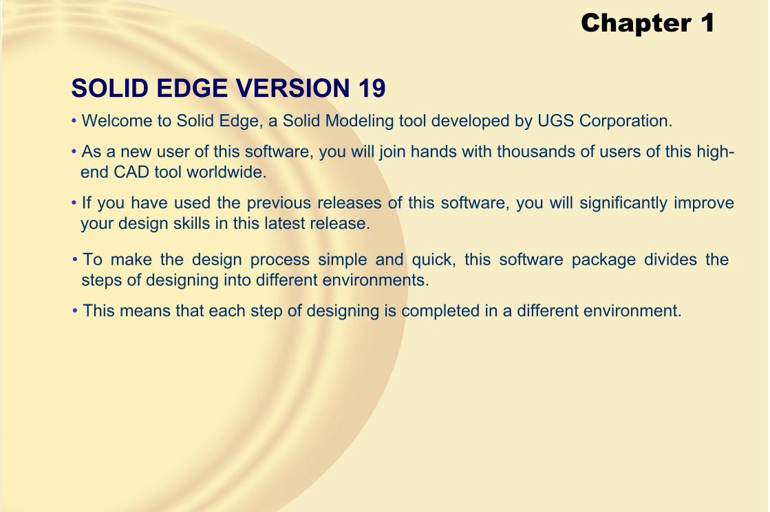
SOLID EDGE VERSION 19• Welcome to Solid Edge, a Solid Modeling tool developed by UGS Corporation.
• As a new user of this software, you will join hands with thousands of users of this high-end CAD tool worldwide.
• If you have used the previous releases of this software, you will significantly improve your design skills in this latest release.
• To make the design process simple and quick, this software package divides the steps of designing into different environments.
• This means that each step of designing is completed in a different environment.

Chapter 1
• Parametric NatureParametric nature of a solid modeling package means that the sketch is driven by dimensions, or in other words, the geometry of a model is controlled by its dimensions.
• Feature-based Modeling• A feature is defined as the smallest building block of a model.
• Any solid model created in Solid Edge is an integration of a number of these features.
• Each feature can be edited individually to bring in any change in the solid model.
Model with simple holes Model with counterbore holes
Chapter 1
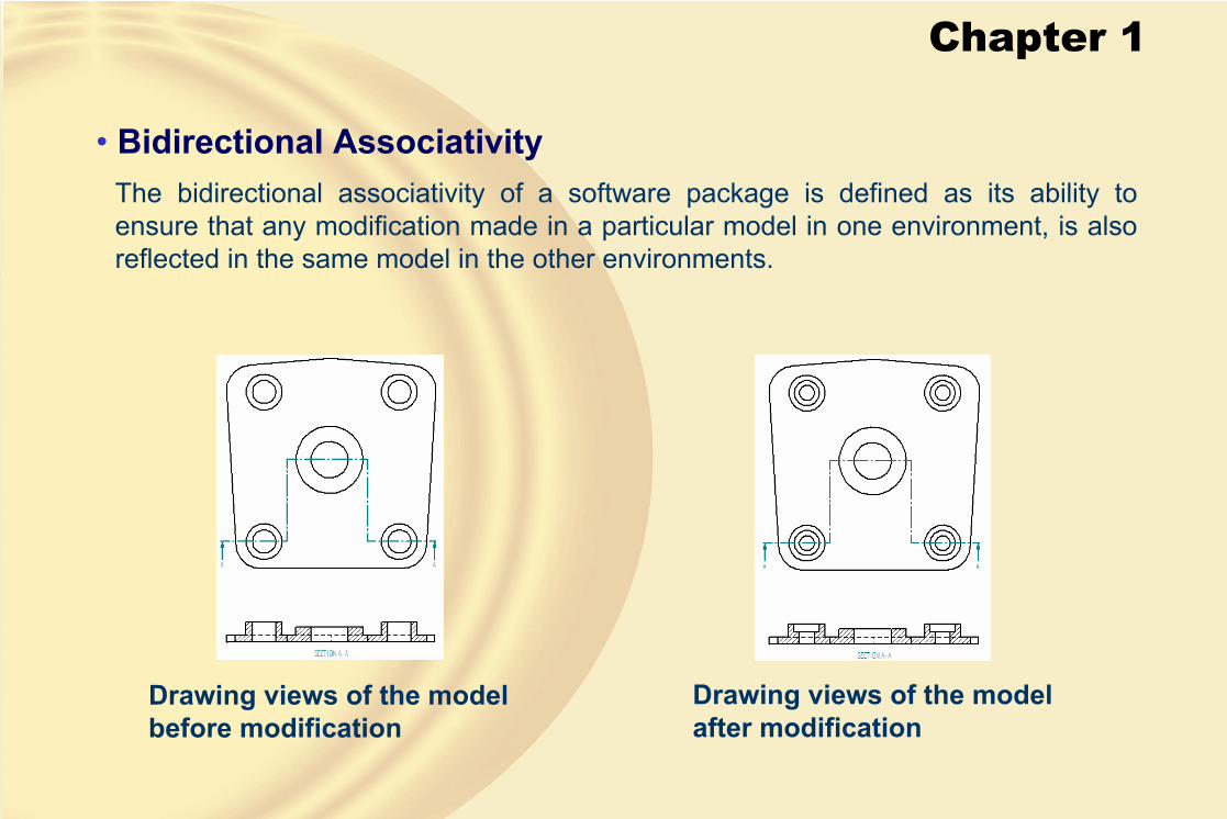
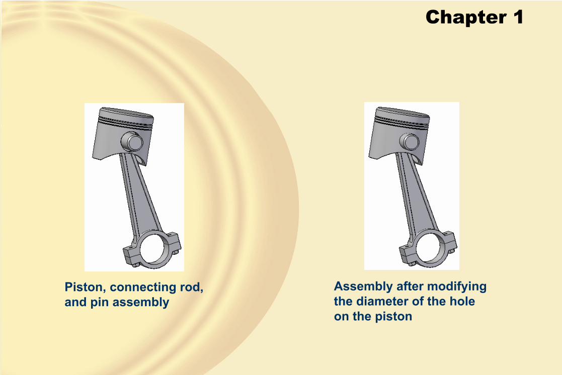
• Bidirectional AssociativityThe bidirectional associativity of a software package is defined as its ability to ensure that any modification made in a particular model in one environment, is also reflected in the same model in the other environments.
Drawing views of the model before modification
Drawing views of the model after modification
Chapter 1
Piston, connecting rod, and pin assembly
Assembly after modifying the diameter of the hole on the piston
Chapter 1
SOLID EDGE ENVIRONMENTS• Part Environment
This environment of Solid Edge is used to create parametric and feature-based solid and surface models.
• Assembly EnvironmentThis environment of Solid Edge is used to create an assembly by assembling the components that were created in the Part environment.
• Draft EnvironmentThis environment is used for the documentation of the parts or assemblies in the form of the drawing views.
Chapter 1
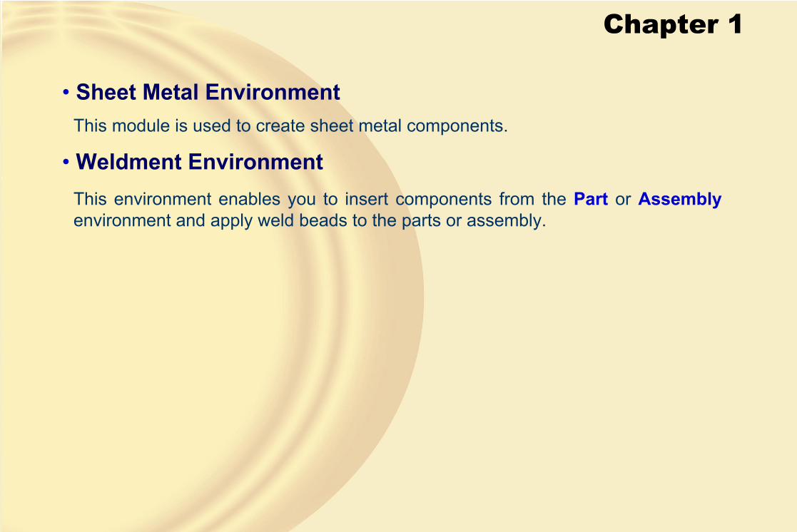
• Sheet Metal EnvironmentThis module is used to create sheet metal components.
• Weldment EnvironmentThis environment enables you to insert components from the Part or Assemblyenvironment and apply weld beads to the parts or assembly.

Chapter 1
SYSTEM REQUIREMENTS FOR SOLID EDGE V19• The system requirements for Solid Edge are as follows:
• An Intel Pentium, AMD Athlon, or AMD Opteron processor-based PC.
• Windows 2000 Professional running Service Pack 3/4 or Windows XP Professional running Service Pack 1.
• Microsoft Internet Explorer 6.0 or later.
• 256MB RAM (512 MB recommended), 640MB hard disk space, OpenGL Accelerator with 65K colors, and CD-ROM for installation.
IMPORTANT TERMS AND DEFINITIONS• Relationship
Relationships are the logical operations that are performed on the selected geometry to make it more accurate in defining its position and size with respect to the other geometry.
Chapter 1
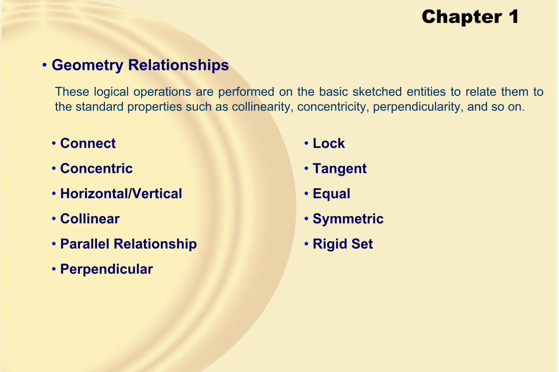
• Geometry RelationshipsThese logical operations are performed on the basic sketched entities to relate them to the standard properties such as collinearity, concentricity, perpendicularity, and so on.
• Connect
• Concentric
• Horizontal/Vertical
• Collinear
• Parallel Relationship
• Perpendicular
• Lock
• Tangent
• Equal
• Symmetric
• Rigid Set
Chapter 1
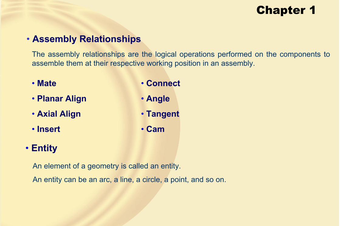
• Assembly RelationshipsThe assembly relationships are the logical operations performed on the components to assemble them at their respective working position in an assembly.
• Mate
• Planar Align
• Axial Align
• Insert
• Connect
• Angle
• Tangent
• Cam
• Entity
An element of a geometry is called an entity.
An entity can be an arc, a line, a circle, a point, and so on.
Chapter 1
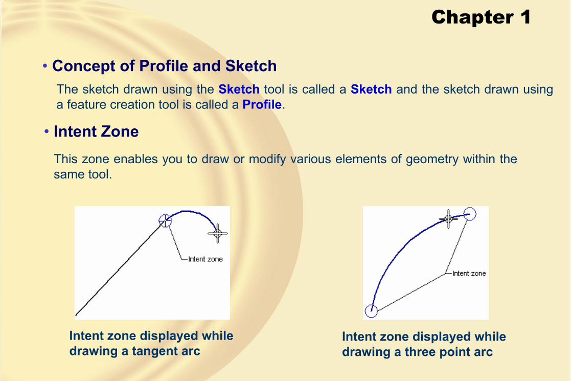
• Concept of Profile and SketchThe sketch drawn using the Sketch tool is called a Sketch and the sketch drawn using a feature creation tool is called a Profile.
• Intent ZoneThis zone enables you to draw or modify various elements of geometry within the same tool.
Intent zone displayed while drawing a tangent arc
Intent zone displayed while drawing a three point arc

Chapter 1
• Prompt LineWhen you choose a tool, the prompt line is displayed below the ribbon bar.
This is helpful, while creating a model, because it provides you with prompt sequences to use a tool.

Chapter 1
GETTING STARTED WITH SOLID EDGE V19Once you have Solid Edge installed on your computer, choose Start > All Programs >Solid Edge V19 > Solid Edge, as shown in the figure.
You can select any environment of Solid Edge to start.
Windows screen with taskbar and application icons
Chapter 1
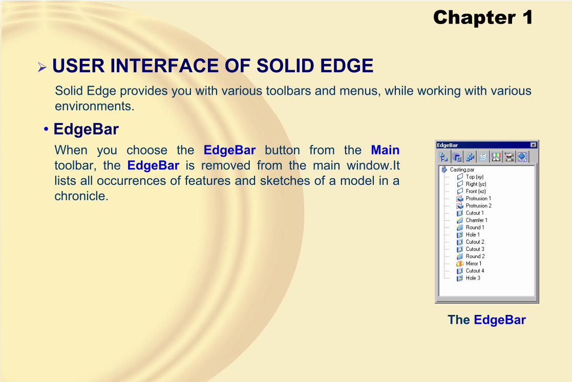
USER INTERFACE OF SOLID EDGESolid Edge provides you with various toolbars and menus, while working with various environments.
• EdgeBarWhen you choose the EdgeBar button from the Maintoolbar, the EdgeBar is removed from the main window.It lists all occurrences of features and sketches of a model in a chronicle.
The EdgeBar

Chapter 1
• Part Environment ToolbarsThere are several toolbars that can be invoked in the Part environment.
• Main Toolbar
The Main toolbar
• Update Relationships
This button is selected to update both the dimensions in the Part environment and the relationships in the Assembly environment.

Chapter 1
• PrintWhen you choose the Print button, the Print dialog box is displayed, as shown in the figure.
The Print dialog box
Chapter 1
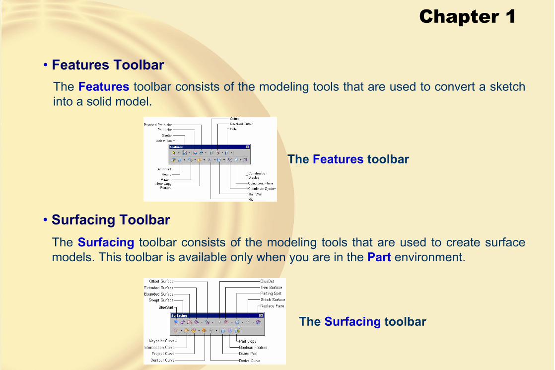
• Features ToolbarThe Features toolbar consists of the modeling tools that are used to convert a sketch into a solid model.
The Features toolbar
• Surfacing ToolbarThe Surfacing toolbar consists of the modeling tools that are used to create surface models. This toolbar is available only when you are in the Part environment.
The Surfacing toolbar

Chapter 1
• Assembly Environment ToolbarThere are several toolbars that can be invoked in the Assembly environment of Solid Edge.
• Assembly Commands ToolbarThe Assembly Commands toolbar is used to create and manage assemblies.
The Assembly Commands toolbar
Chapter 1
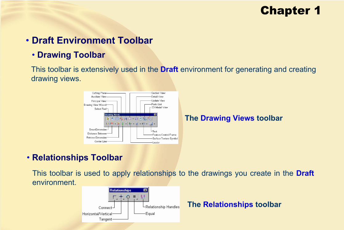
• Draft Environment Toolbar• Drawing ToolbarThis toolbar is extensively used in the Draft environment for generating and creating drawing views.
The Drawing Views toolbar
• Relationships Toolbar
This toolbar is used to apply relationships to the drawings you create in the Draftenvironment.
The Relationships toolbar
Chapter 1
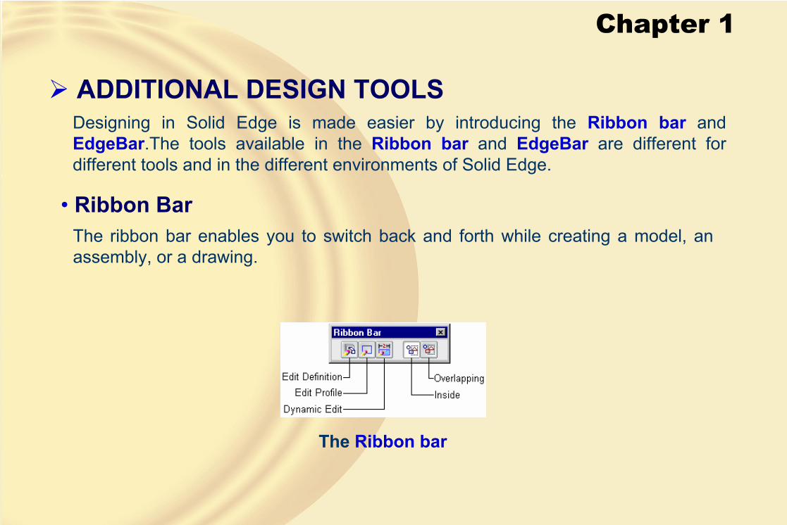
ADDITIONAL DESIGN TOOLSDesigning in Solid Edge is made easier by introducing the Ribbon bar andEdgeBar.The tools available in the Ribbon bar and EdgeBar are different for different tools and in the different environments of Solid Edge.
• Ribbon Bar
The Ribbon bar
The ribbon bar enables you to switch back and forth while creating a model, an assembly, or a drawing.

Chapter 1
• Plane or Sketch StepYou can choose this button from the ribbon bar and redefine the sketch plane.
• Draw Profile StepUsing the Draw Profile Step button, you can either select a profile from the drawing window or sketch a one.
• Side StepThe Side Step button is used to specify the side of the sketch to or from which the material will be added or removed.
• Extent StepThe Extent Step button is used to specify the depth of the material addition.

Chapter 1
• Treatment StepThis step is available in some of the sketched-based features and is used to add a draft or a crown feature to the model.
• QuickPickThis tool enables you to select elements from the drawing window.
This tool is used when the elements or components are overlapping and you need to make a selection.
The QuickPick list box

Chapter 1
This book uses white color as the background.
To change the background color, choose Tools > Options to display the Optionsdialog box.
Choose the Colors tab in the dialog box to display various colors, as shown in the figure.
COLOR SCHEME IN THIS TEXTBOOK
Colors tab of the Options dialog box

Chapter 1
UNITS FOR DIMENSIONSWhen you install Solid Edge 19, you need to specify the units of dimensions that will be used in all the environments of Solid Edge.
The units can be in inches or millimeters.
AUTOMATIC SAVING OPTIONIn Solid Edge, you can set the option to save the files automatically after a regular interval of time.
To set this option, choose Tools > Options to display the Options dialog box.
Choose the Save tab and select the Automatically preserve documents by check box.
Chapter 2
Learning Objectives:• Understand the need for the sketching environment
• Understand the base reference planes that can be selected to create sketches
• Understand various drawing display tools
• Understand various sketching tools
• Use various selection methods
• Delete sketched entities

Chapter 2
THE SKETCHING ENVIRONMENT• Most of the designs created in a solid modeling tool consist of the profile-based
features, placed features, and reference features.
• A profile is a combination of a number of two-dimensional (2D) entities such as lines, arcs, circles, and so on.
Solid model Profile of the solid model
Chapter 2
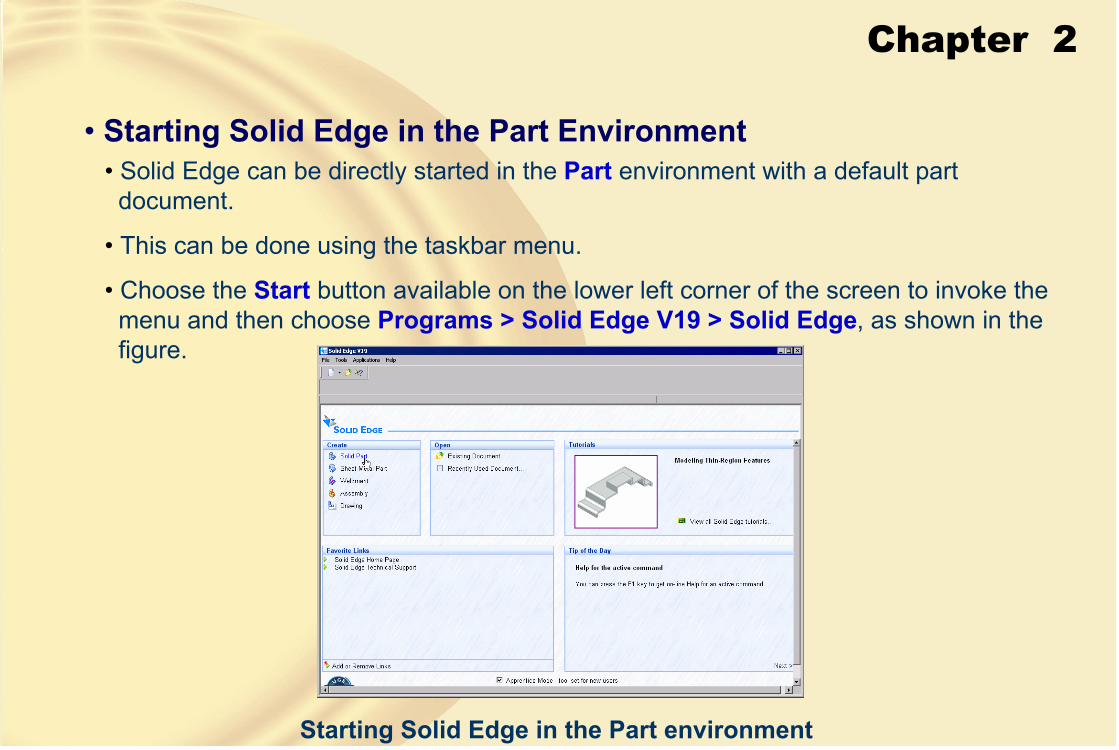
• Starting Solid Edge in the Part Environment• Solid Edge can be directly started in the Part environment with a default part
document.
• This can be done using the taskbar menu.
• Choose the Start button available on the lower left corner of the screen to invoke the menu and then choose Programs > Solid Edge V19 > Solid Edge, as shown in the figure.
Starting Solid Edge in the Part environment

Chapter 2
• Starting a New Part Document Using the New Dialog BoxChoose the New button from the Main toolbar to display the New dialog box, as shown in the figure.
The New dialog box
Chapter 2
• General TabThe General tab provides the default templates for starting the Assembly, Draft,Part, Sheet Metal and Weldment environment.
• More TabThe More tab provides the Metric and English templates for starting files in various environments of Solid Edge.
• Quicksheet Tab
The Quicksheet tab provides the drawing template with empty (blank) drawing views of a part or an assembly.
• Reports Tab
The Reports tab provides the template for generating reports for the Solid Edge assemblies.

Chapter 2
• Large Icon ButtonThe Large Icon button is used to display the templates in various tabs of the Newdialog box in the form of large icons.
• List ButtonThe List button is used to display the templates in various tabs of the New dialog box in the form of a list.
• Detail ButtonThe Detail button is used to list the details of the templates in various tabs of the Newdialog box.
• Preview Area
The Preview area shows the preview of the selected template.
Chapter 2
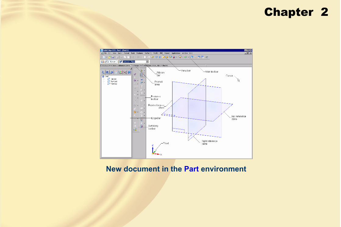
New document in the Part environment

Chapter 2
INVOKING THE SKETCHING ENVIRONMENTIf you select any of the three reference planes shown in Figure A, it will be oriented parallel to the screen and the sketching environment will be invoked to draw the profile for the protrusion feature.
Figure A Screen appearance in the sketching environment of Solid Edge

Chapter 2
THE DRAWING DISPLAY TOOLSThe drawing display tools are an integral part of any solid modeling tool.
They enable you to zoom and pan the drawing so that you can view it clearly.
• Zooming to an AreaThe Zoom Area tool allows you to zoom on to a particular area by defining a box around it.
• Dynamic ZoomingYou can use this tool to increase the display area to double the current size.
• Fitting all Entities in the Current DisplayThe Fit tool enables you to modify the drawing display area such that all entities in the drawing fit in the current display.
Chapter 2
• Panning DrawingsThe Pan tool allows you to dynamically pan drawings in the drawing window.
• Restoring the Original Orientation of the Sketching PlaneThe Sketch View tool enables you to restore the original orientation that was active when you invoked the sketching environment.

Chapter 2
SKETCHING TOOLSAll tools required to create a profile or a sketch in Solid Edge are available in the Drawtoolbar.
• Drawing Lines
Line ribbon bar
In Solid Edge, the Line tool enables you to draw straight lines and tangent or normal arcs originating from the endpoint of a selected line.
Chapter 2
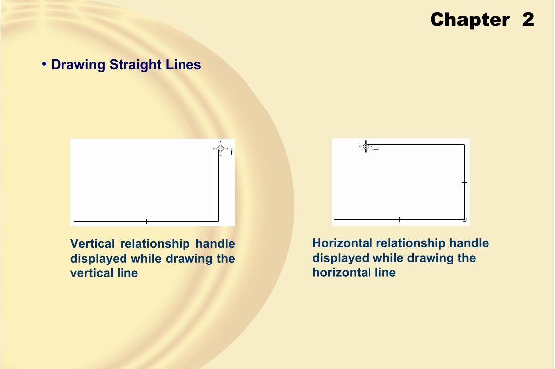
• Drawing Straight Lines
Vertical relationship handle displayed while drawing the vertical line
Horizontal relationship handle displayed while drawing the horizontal line
Chapter 2
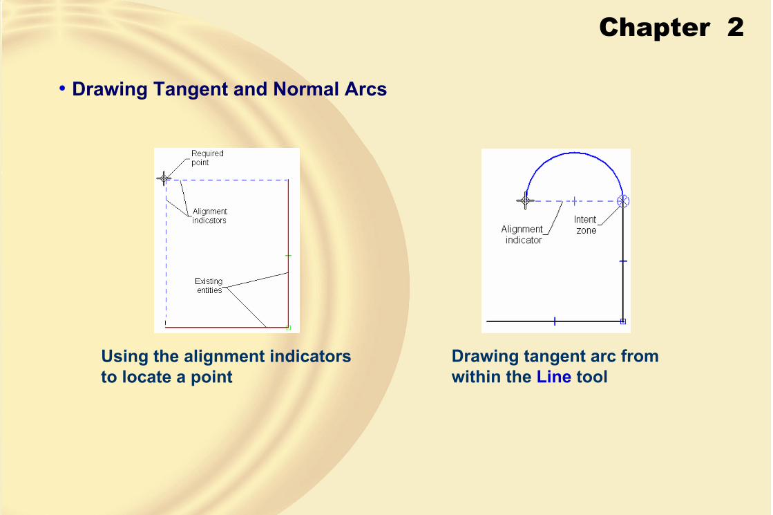
• Drawing Tangent and Normal Arcs
Using the alignment indicators to locate a point
Drawing tangent arc from within the Line tool

Chapter 2
• Drawing CirclesIn Solid Edge, you can draw circles using three methods.
• Drawing a Circle by Specifying the Center Point and Radius
Circle drawn using the Circleby Center method
• Drawing a Circle by Specifying Three Points
Drawing circle using the Circle by 3 Points method
Chapter 2
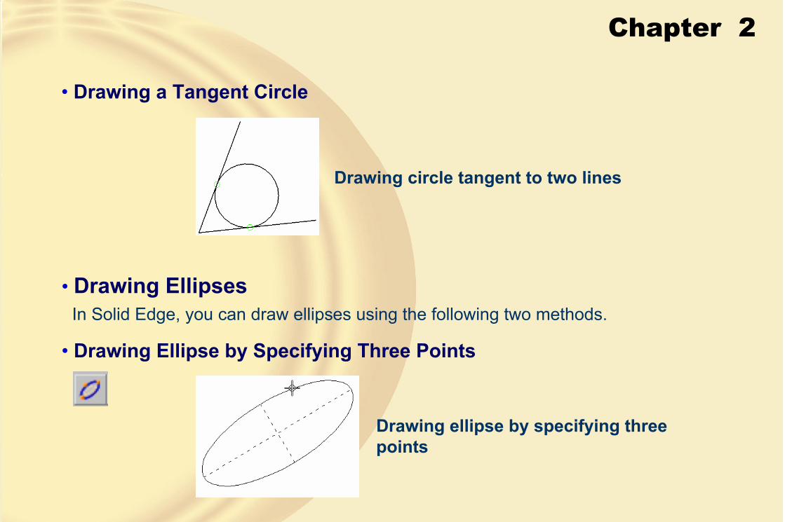
• Drawing a Tangent Circle
Drawing circle tangent to two lines
• Drawing EllipsesIn Solid Edge, you can draw ellipses using the following two methods.
• Drawing Ellipse by Specifying Three Points
Drawing ellipse by specifying three points
Chapter 2
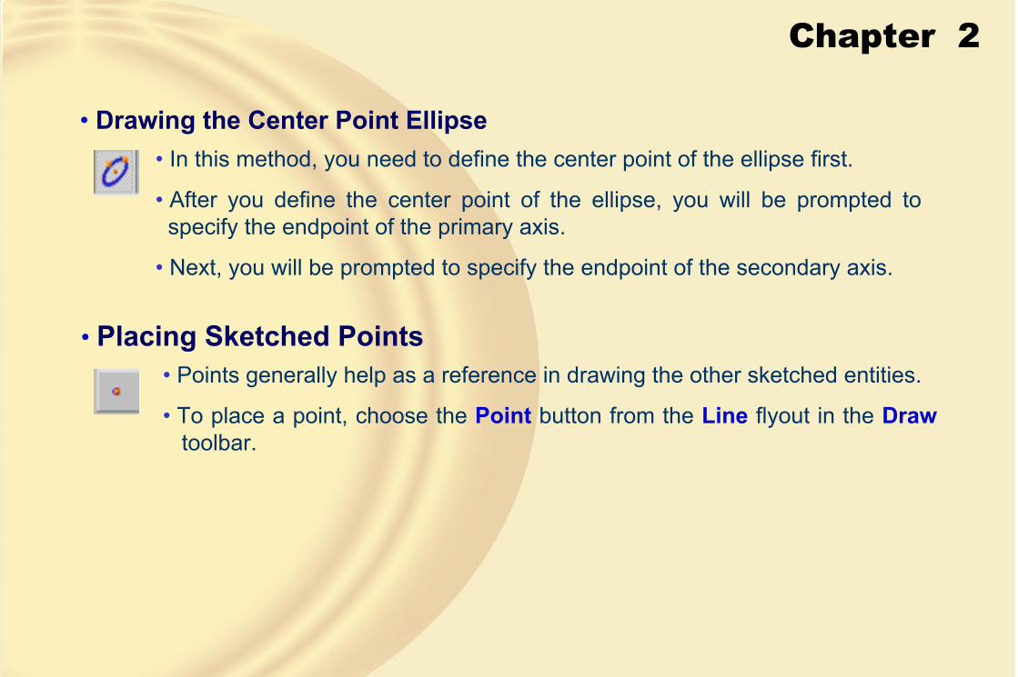
• Drawing the Center Point Ellipse• In this method, you need to define the center point of the ellipse first.
• After you define the center point of the ellipse, you will be prompted to specify the endpoint of the primary axis.
• Next, you will be prompted to specify the endpoint of the secondary axis.
• Placing Sketched Points• Points generally help as a reference in drawing the other sketched entities.
• To place a point, choose the Point button from the Line flyout in the Drawtoolbar.

Chapter 2
• Drawing ArcsIn Solid Edge, you can draw arcs using three methods.
• Drawing a Tangent or a Normal ArcThis method of drawing arcs is similar to drawing tangent and normal arcs from within the Line tool.
• Drawing a Three-Point Arc
Drawing an arc using the Arc by 3 Points method

Chapter 2
• Drawing a Center Point Arc
Drawing an arc using the Arc by Center method
• Drawing Rectangles
Rectangle drawn at an angle

Chapter 2
• Drawing CurvesThe Curve tool allows you to draw curves using two methods: specifying points in the drawing window and dragging the cursor in the drawing window.
• Drawing a Curve by Dragging the Cursor
Curve drawn by dragging the cursor in the drawing window

Chapter 2
• Drawing a Curve by Specifying Points in the Drawing Window
Curve drawn by specifying the points in the drawing window
• Converting Sketched Entities into CurvesIn Solid Edge, you can convert the sketched entities such as lines, arcs, circles, and ellipses into bezier spline curves using the Convert to Curve tool.
Chapter 2
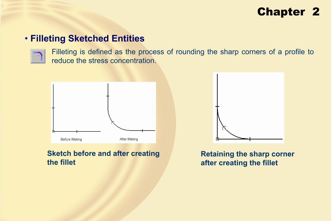
• Filleting Sketched EntitiesFilleting is defined as the process of rounding the sharp corners of a profile to reduce the stress concentration.
Sketch before and after creating the fillet
Retaining the sharp corner after creating the fillet

Chapter 2
• Chamfering Sketched EntitiesChamfering is defined as the process of beveling the sharp corners of a profile to reduce the stress concentration.
Selecting lines to create chamfer

Chapter 2
SELECTING THE SKETCHED ENTITIESWhen you choose the Select Tool button from the Draw toolbar, the select mode will be invoked. In this mode, you can select the sketched entities available in the drawing window by clicking on them.
• Inside
• Outside
• Overlapping
• Inside and Overlapping
• Outside and Overlapping
DELETING THE SKETCHED ENTITIESTo delete the sketched entities, select them using any of the object selection methods.
Chapter 2
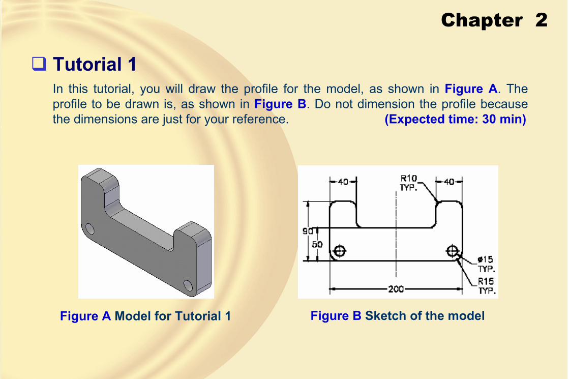
Tutorial 1In this tutorial, you will draw the profile for the model, as shown in Figure A. The profile to be drawn is, as shown in Figure B. Do not dimension the profile because the dimensions are just for your reference. (Expected time: 30 min)
Figure A Model for Tutorial 1 Figure B Sketch of the model

Chapter 2
1. Start Solid Edge and then start a new file in the Part environment.
Figure C Sketch after drawing lines
2. Choose the sketch button and select the front plane as the sketching plane and invoke the sketching environment.
3. Draw the outer loop of the profile using the Line tool, as shown in Figure C.
Chapter 2
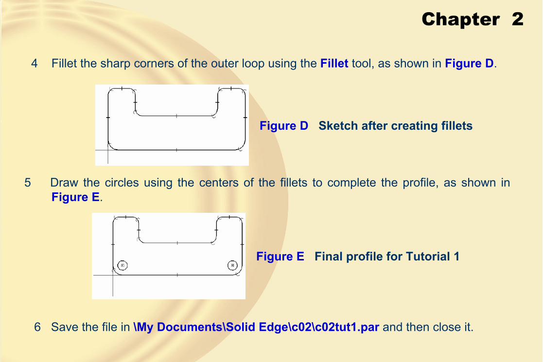
4 Fillet the sharp corners of the outer loop using the Fillet tool, as shown in Figure D.
Figure D Sketch after creating fillets
5 Draw the circles using the centers of the fillets to complete the profile, as shown in Figure E.
Figure E Final profile for Tutorial 1
6 Save the file in \My Documents\Solid Edge\c02\c02tut1.par and then close it.

Chapter 2
Tutorial 2In this tutorial, you will draw the profile of the model, as shown in Figure A. The profile to be drawn is, as shown in Figure B. Do not dimension the profile because the dimensions are just for your reference. (Expected time: 30 min)
Figure A Model for Tutorial 2 Figure B Profile for Tutorial 2

Chapter 2
1. Start a new part file using the New dialog box, as shown in Figure C.
Figure C The New dialog box to start a new file in Solid Edge
2. Choose the Sketch button and select right plane as the sketching plane and invokethe sketching environment.

Chapter 2
3. Draw the profile of the model using the Line tool, as shown in Figure D and Figure E.
Figure E Profile for Tutorial 2Figure D Horizontal and vertical alignment indicators displayed to define the endpoint of the arc
4. Save the file in \My Documents\Solid Edge\c02\c02tut2.par and then close it.

Chapter 2
Tutorial 3In this tutorial, you will draw the profile for the base feature of the model, as shown in Figure A. The profile to be drawn is, as shown in Figure B. Do not dimension the profile because the dimensions are just for your reference. (Expected time: 30 min)
Figure A Model for Tutorial 3 Figure B Profile for Tutorial 3
Chapter 2
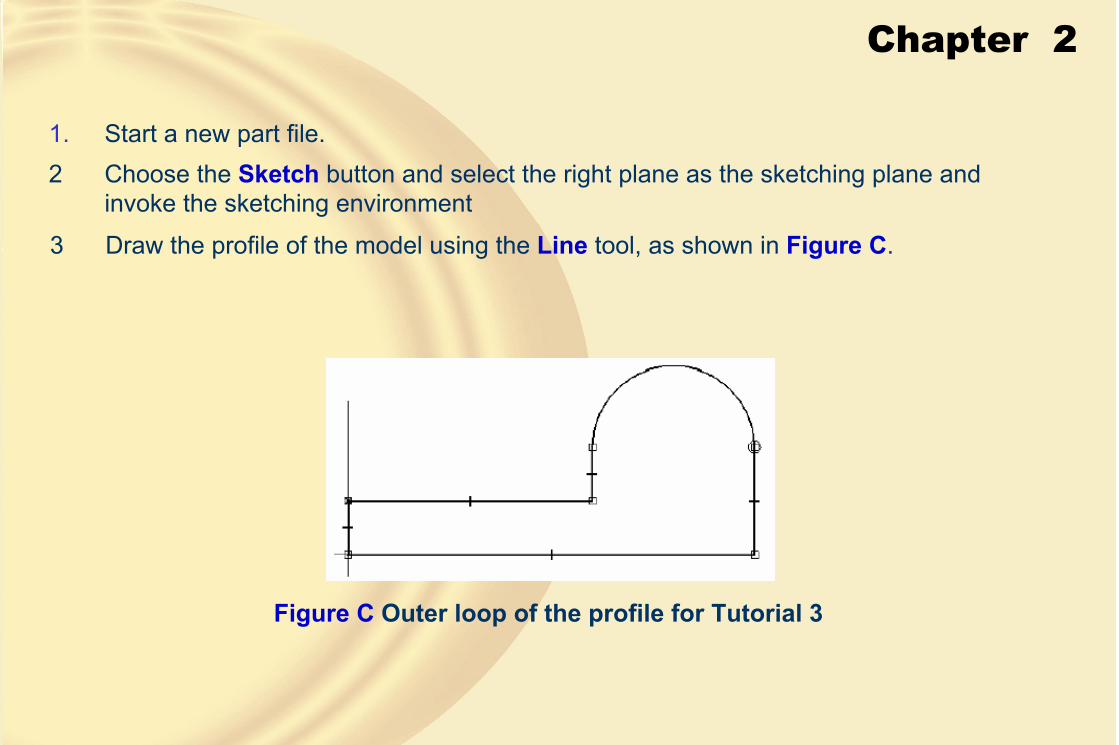
1. Start a new part file.
3 Draw the profile of the model using the Line tool, as shown in Figure C.
Figure C Outer loop of the profile for Tutorial 3
2 Choose the Sketch button and select the right plane as the sketching plane and invoke the sketching environment
Chapter 2
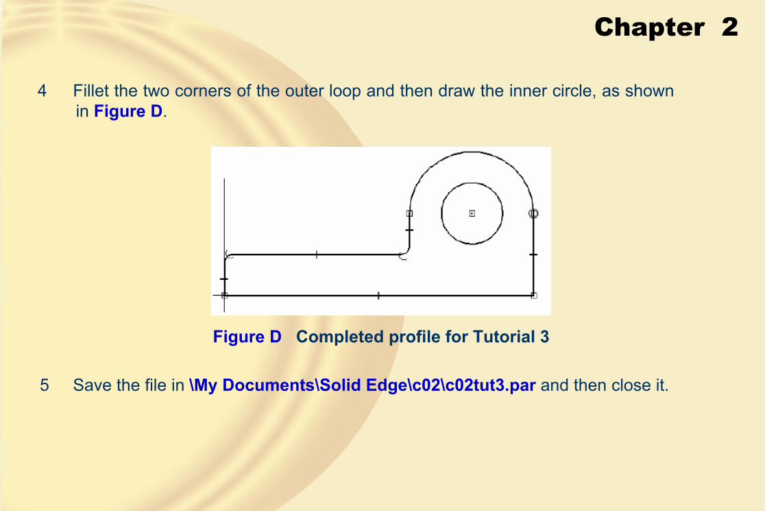
4 Fillet the two corners of the outer loop and then draw the inner circle, as shown in Figure D.
Figure D Completed profile for Tutorial 3
5 Save the file in \My Documents\Solid Edge\c02\c02tut3.par and then close it.

Chapter 2
Exercise 1Draw the profile of the base feature of the model, as shown in Figure A. The profile to be drawn is, as shown in Figure B. Do not dimension the profile because the dimensions are just for your reference. (Expected time: 30 min)
Figure A Model for Exercise 1 Figure B Profile for Exercise 1
Chapter 2
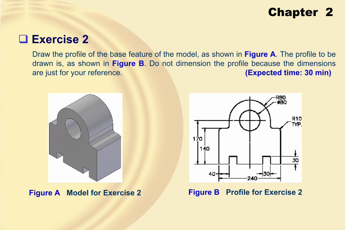
Exercise 2Draw the profile of the base feature of the model, as shown in Figure A. The profile to be drawn is, as shown in Figure B. Do not dimension the profile because the dimensions are just for your reference. (Expected time: 30 min)
Figure A Model for Exercise 2 Figure B Profile for Exercise 2
Chapter 3
Learning Objectives:• Understand different types of geometric relationships in Solid Edge
• Force additional geometric relationships to sketches
• View and delete geometric relationships from sketches
• Understand the methods of dimensioning in Solid Edge
• Modify values of dimensions
• Add automatic dimensions to the sketches while drawing them

Chapter 3
� GEOMETRIC RELATIONSHIPSGeometric relationships are logical operations performed on the sketching entities to relate them to the other sketched entities using standard properties such as collinearity, concentricity, tangency, and so on.
• Connect Relationship
Selecting the keypoint of the first entity and then the second entity
One point connect relationship applied between the two entities
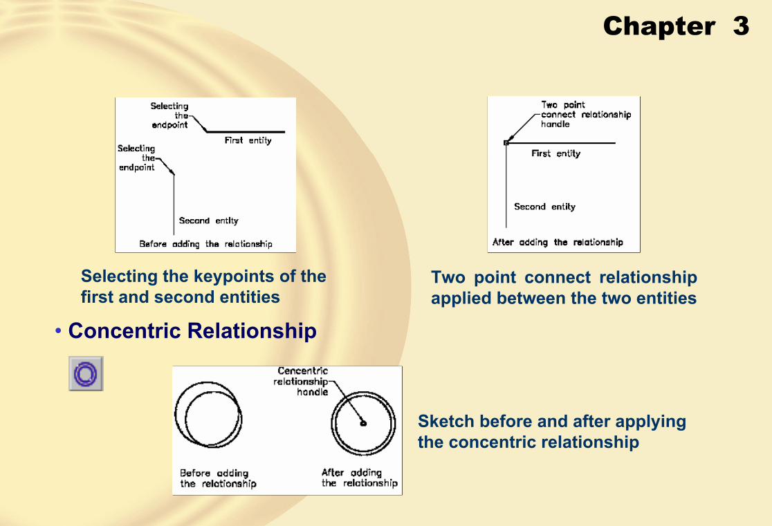
Chapter 3
Selecting the keypoints of the first and second entities
Two point connect relationship applied between the two entities
• Concentric Relationship
Sketch before and after applying the concentric relationship

Chapter 3
• Horizontal/Vertical Relationship
This relationship forces an inclined line to become horizontal or vertical.
• Collinear RelationshipThis relationship forces the selected line segments to be placed in the same line.
• Parallel RelationshipThis relationship forces a selected line segment to become parallel to another line segment.
• Perpendicular RelationshipThis relationship forces a selected line to become perpendicular to another line, arc, circle, or ellipse.

Chapter 3
• Lock RelationshipThis constraint is used to fix the orientation or location of the selected sketched entity or a keypoint of a sketched entity.
• Rigid Set Relationship
This relationship is used to group the selected sketched entities into a rigid set.
• Tangent Relationship
Making the entities tangent Making a curve tangent to a chain of tangentially connected entities

Chapter 3
• Equal RelationshipThis relationship can be used either for line segments, ellipses, or for arcs and circles.
• Symmetric Relationship
Selecting the entities to apply the symmetry relationship
Entities after applying the symmetry relationship

Chapter 3
• Setting the Symmetry AxisWhen you invoke the symmetric relationship, you will not be prompted to select the axis of symmetry. The symmetry axis set earlier is automatically selected as the axis of symmetry.
� CONFLICTS IN RELATIONSHIPSSometimes, when you apply more relationships than are required, the relationships conflict and the Solid Edge information box is displayed, as shown in the figure.
The Solid Edge information box
• Controlling the Display of Relationship HandlesIn Solid Edge V19, the Relationship Handles button is chosen by default. As a result, the handles of all relationships are displayed in the sketch.

Chapter 3
� DELETING RELATIONSHIPSYou can delete the applied relationship by selecting its handle and pressing the DELETE key.
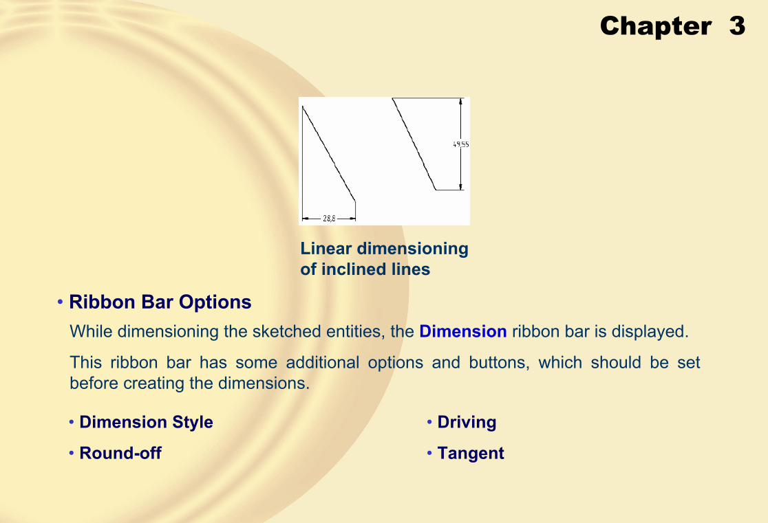
� DIMENSIONING THE SKETCHED ENTITIES• Adding Linear Dimensions
Linear dimensioning of lines Linear dimensioning of points
Chapter 3
Linear dimensioning of inclined lines
• Ribbon Bar OptionsWhile dimensioning the sketched entities, the Dimension ribbon bar is displayed.
This ribbon bar has some additional options and buttons, which should be set before creating the dimensions.
• Dimension Style
• Round-off
• Driving
• Tangent

Chapter 3
• Prefix
When you choose the Prefix button, the Dimension Prefix dialog box will be displayed, as shown in the figure.
• Dimension Type
Sketch dimensioned using the limits and tolerance dimension types
The Dimension Prefix dialog box

Chapter 3
• Inspection
This button is chosen to add an oblong around the dimension for inspection.
• Adding Aligned Dimensions
Aligned dimensioning of lines Aligned dimensioning of points

Chapter 3
• Adding Angular Dimensions
• Angular Dimensioning using Two Line Segments
Angular dimensions are used to dimension angles.
Angular dimensioning of two lines
Linear dimensioning of lines Linear dimensioning of points
Chapter 3
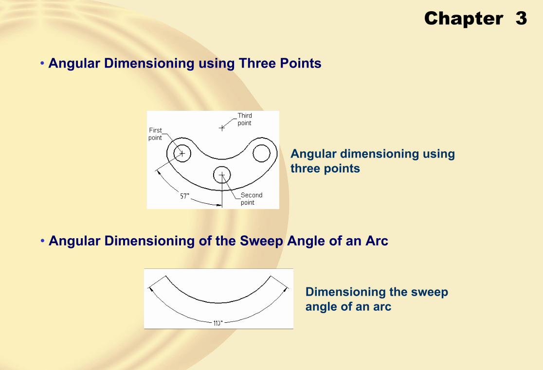
• Angular Dimensioning using Three Points
Angular dimensioning using three points
• Angular Dimensioning of the Sweep Angle of an Arc
Dimensioning the sweep angle of an arc
Chapter 3
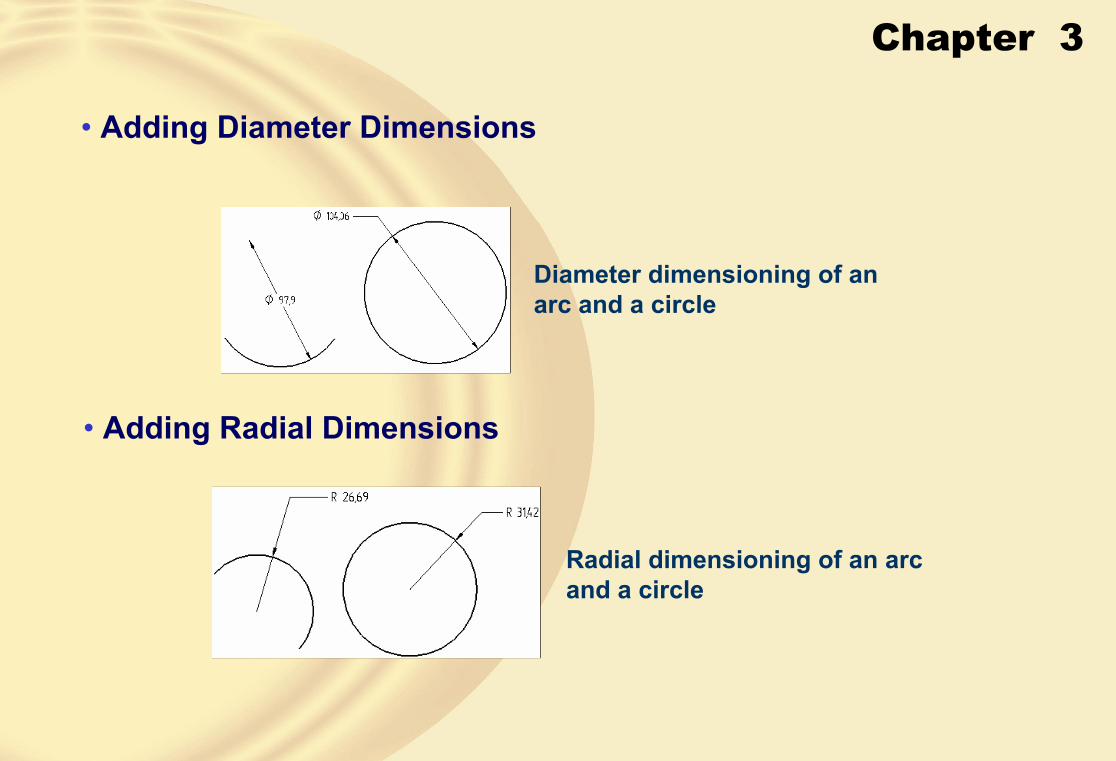
• Adding Diameter Dimensions
Diameter dimensioning of an arc and a circle
• Adding Radial Dimensions
Radial dimensioning of an arc and a circle
Chapter 3
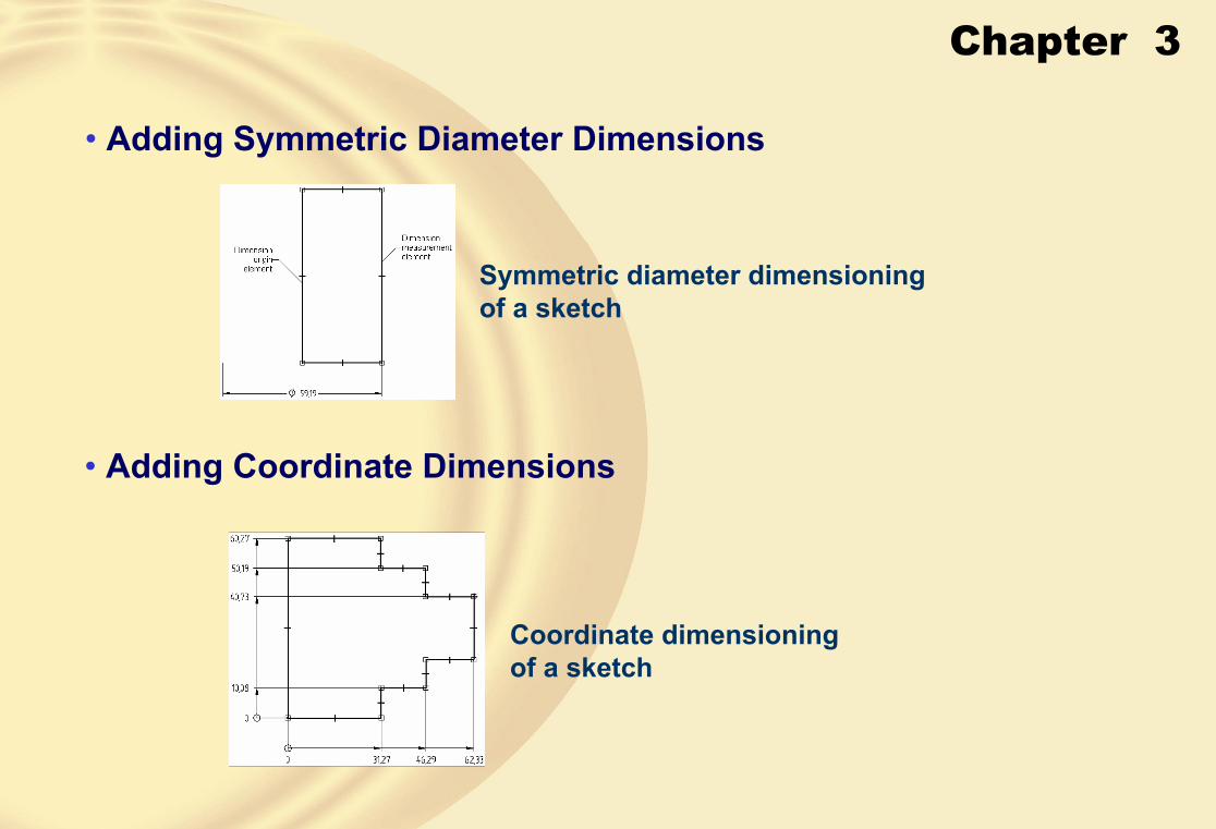
• Adding Symmetric Diameter Dimensions
Symmetric diameter dimensioning of a sketch
• Adding Coordinate Dimensions
Coordinate dimensioning of a sketch

Chapter 3
• Adding Angular Coordinate Dimensions
Angular coordinate dimensioning of a sketch
• ADDING AUTOMATIC DIMENSIONS• ADDING AUTOMATIC DIMENSIONSThis tool allows you to add the dimensions to the sketched entities automatically when you draw them.This tool allows you to add the dimensions to the sketched entities automatically when you draw them.
The IntelliSketch dialog boxThe IntelliSketch dialog box

Chapter 3
� MEASURING SKETCHED ENTITIES• Measuring Distances
Measuring distance between two keypoints
This tool allows you to measure the linear distance between any two selected points. To measure the distance, invoke this tool from the Inspect menu; you will be prompted to click for the first point.
This tool allows you to measure the linear distance between any two selected points. To measure the distance, invoke this tool from the Inspect menu; you will be prompted to click for the first point.

Chapter 3
• Measuring the Total Length of a Closed Loop or an Open SketchThis tool allows you to measure the total length of a closed loop or an open sketch. When you invoke this tool, the ribbon bar will be displayed and you will be prompted to click on the element(s) to be measured.
• Measuring Area
Measuring the area of a closed loop

Chapter 3
• Calculating the Area PropertiesThis tool allows you to calculate the properties of a selected area.
On invoking this tool, you will be prompted to click on the area.
Choose the Calculate button to display the Area Properties dialog box, as shown in the figure.
The Area Properties dialog box

Chapter 3
� Tutorial 1In this tutorial, you will draw the profile for the model, as shown in Figure A. The profile, as shown in Figure B, should be symmetric about the origin. You will not use the edit boxes available in the ribbon bar to enter the values of the entities. Instead, you will use the parametric dimensions to complete the sketch. (Expected time: 30min)
Figure A Model for Tutorial 1 Figure B Profile to be drawn for Tutorial 1

Chapter 3
1. Start Solid Edge in the Part environment.
Figure C Outer loop of the profile
3. Using the Line tool, draw the outer loop of the profile, as shown in Figure C.
2. Choose the Sketch button and select the front plane as the sketching plane.
Chapter 3
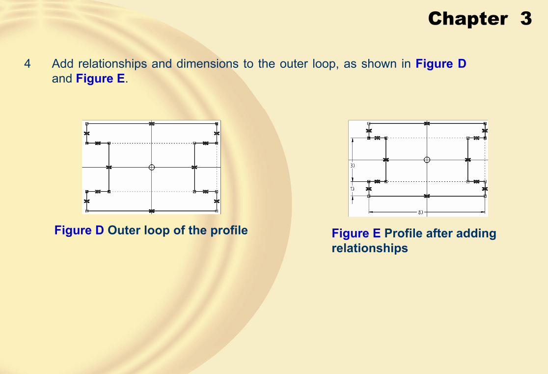
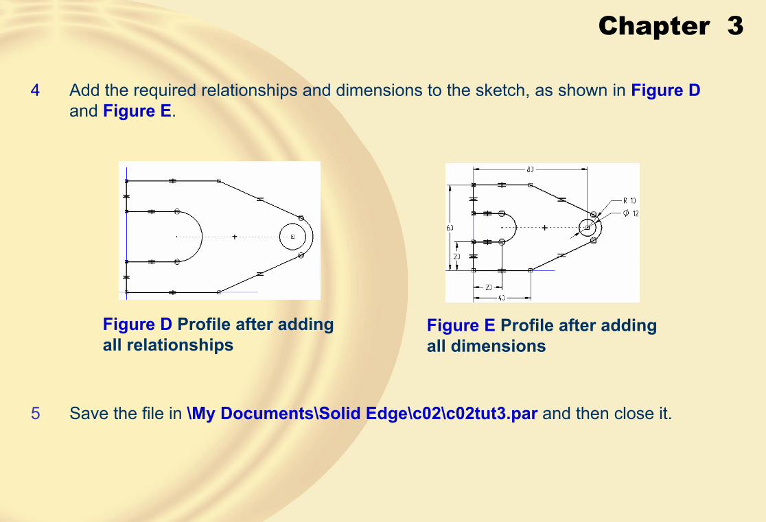
4 Add relationships and dimensions to the outer loop, as shown in Figure D and Figure E.
Figure D Outer loop of the profile Figure E Profile after adding relationships

Chapter 3
5 Draw a rectangle inside the outer loop using the Rectangle tool.
6 Add dimensions to the rectangle to complete the sketch, as shown in Figure F.
Figure F Final profile after adding all the dimensions
7 Save the file in \My Documents\Solid Edge\c02\c02tut1.par and then close it.
Chapter 3
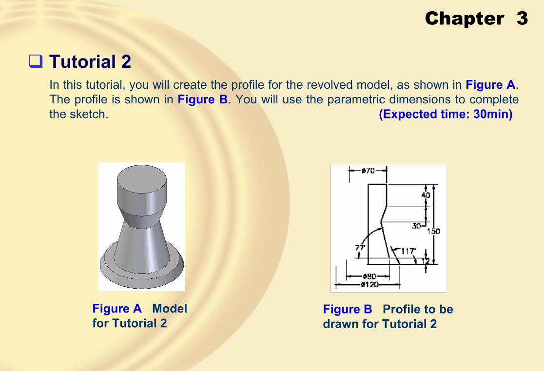
� Tutorial 2In this tutorial, you will create the profile for the revolved model, as shown in Figure A. The profile is shown in Figure B. You will use the parametric dimensions to complete the sketch. (Expected time: 30min)
Figure A Model for Tutorial 2
Figure B Profile to be drawn for Tutorial 2

Chapter 3
1. Start a new part file.
3 Draw the required profile using the Line tool, as shown in Figure C.
Figure C Profile for the revolved model
2. Choose the Sketch button and select the front plane as the sketching plane.
Chapter 3
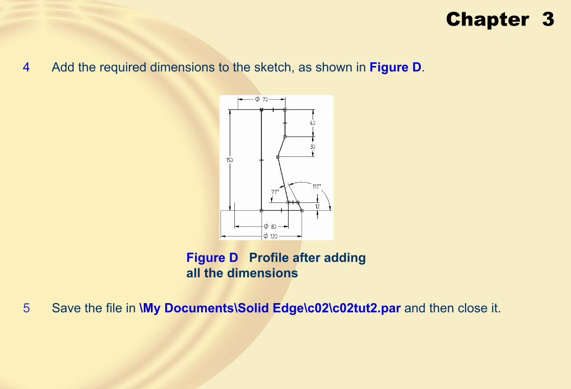
Figure D Profile after adding all the dimensions
4 Add the required dimensions to the sketch, as shown in Figure D.
5 Save the file in \My Documents\Solid Edge\c02\c02tut2.par and then close it.

Chapter 3
� Tutorial 3In this tutorial, you will create the profile for the model, as shown in Figure A. The profile is, as shown in Figure B. You will use the relationships and parametric dimensions to complete the sketch. (Expected time: 30 min)
Figure A Model for Tutorial 3 Figure B Profile to be drawn for Tutorial 3

Chapter 3
1 Start a new part file.
3 Draw the required profile using the Line and Circle by Center tool, as shown in Figure C.
Figure C Profile after drawing all entities
2 Choose the Sketch button and select the top plane as the sketching plane.
Chapter 3
Figure D Profile after adding all relationships
4 Add the required relationships and dimensions to the sketch, as shown in Figure Dand Figure E.
Figure E Profile after adding all dimensions
5 Save the file in \My Documents\Solid Edge\c02\c02tut3.par and then close it.

Chapter 3
� Exercise 1Draw the profile for the base feature of the model, as shown in Figure A. The profile to be drawn is, as shown in Figure B. Use the relationships and parametric dimensions to complete the profile. (Expected time: 30 min)
Figure A Model for Exercise 1 Figure B Profile for Exercise 1

Chapter 3
� Exercise 2Draw the profile for the base feature of the model, as shown in Figure A. The profile to be drawn is, as shown in Figure B. Use the relationships and parametric dimensions to complete the profile. (Expected time: 30 min)
Figure A Solid model for Exercise 2
Figure B Profile for Exercise 2

Chapter 4
Learning Objectives:• Edit sketches using the editing tools in Solid Edge
• Write text in the sketching environment
• Edit sketched entities by using the ribbon bar and by dragging
• Convert sketches into base features by extruding and revolving
• Rotate the view of the model dynamically in 3D space
• Change the view and the display type of the models

Chapter 4
� EDITING SKETCHES• Editing is a very important part of sketching in any solid modeling tool.
• You need to edit the sketches during various stages of a design.
• Trimming the Sketched Entities
Selecting the entities to be trimmed Sketch after trimming the entities

Chapter 4
• Extending the Sketched Entities
Selecting the entities to be extended Sketch after extending the entities
Chapter 4
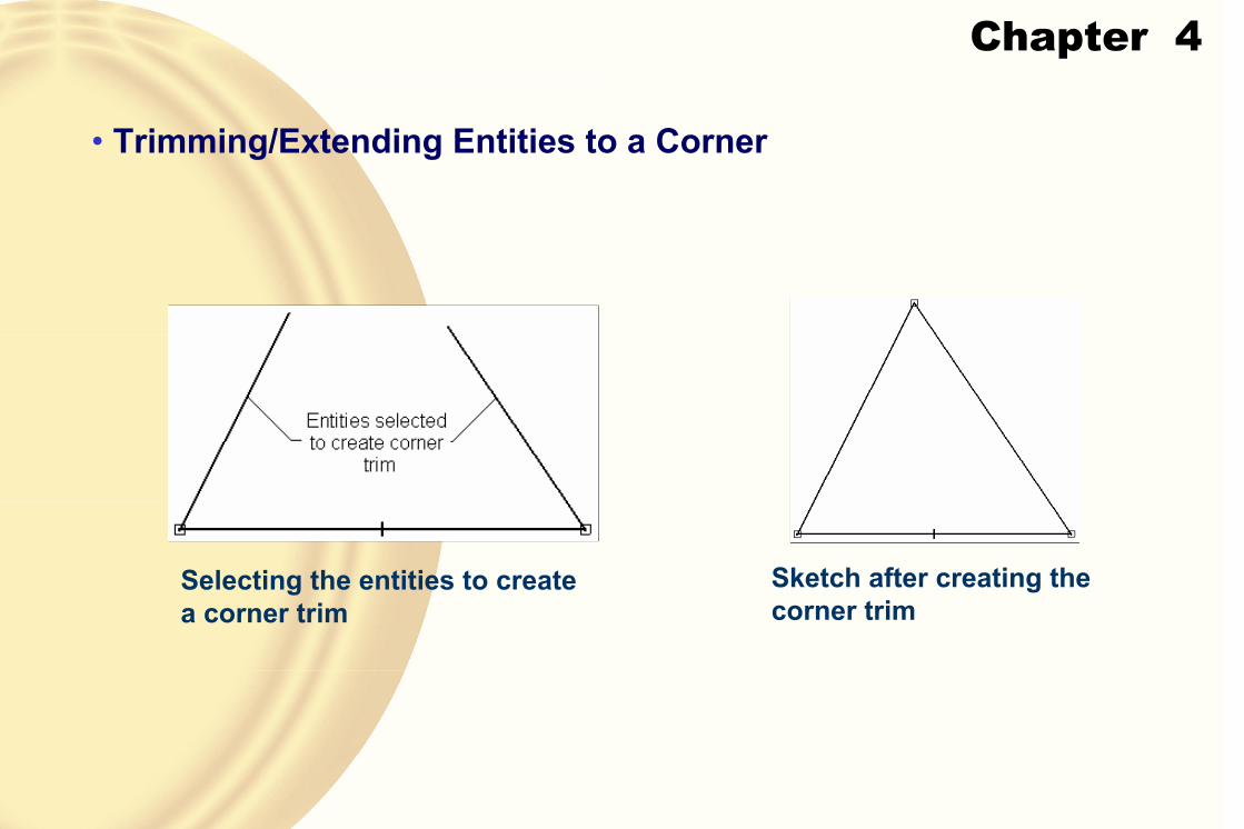
• Trimming/Extending Entities to a Corner
Selecting the entities to create a corner trim
Sketch after creating the corner trim

Chapter 4
• Creating Offset Copies
Multiple triangles created by offsetting the outer triangle
• Creating Symmetric Offset Copies
Using symmetric offset to create a slot

Chapter 4
To create a symmetric offset, choose the Symmetric Offset button from the Offsetflyout; the Symmetric Offset Options dialog box will be displayed, as shown in the figure.
The Symmetric Offset Options dialog box
• WidthThe Width edit box is used to set the width of the slot that will be created by the symmetric offset.

Chapter 4
• RadiusIf the selected entities have some bends, which result in sharp corners, then this edit box will define the radius of the arc at the inside of the resulting slot.
Slots with different fillet radii
• Cap Type AreaThis area provides the options to specify the cap type at the end of the slots.
• Line
Line cap with no fillet Line cap with fillet

Chapter 4
• Arc
This radio button is selected to place an arc at the end of the slot.• Offset Arc
This radio button is selected to place an offset arc at the end of the slot.
• Apply radii if fillet radius = 0This check box is selected to create an arc at the outer corner of the resulting slot if the value of the radius in the Radius edit box is set to zero.
• Show this dialog when the command beginsThis check box is selected to display this dialog box whenever you invoke the Symmetric Offset tool.
Chapter 4
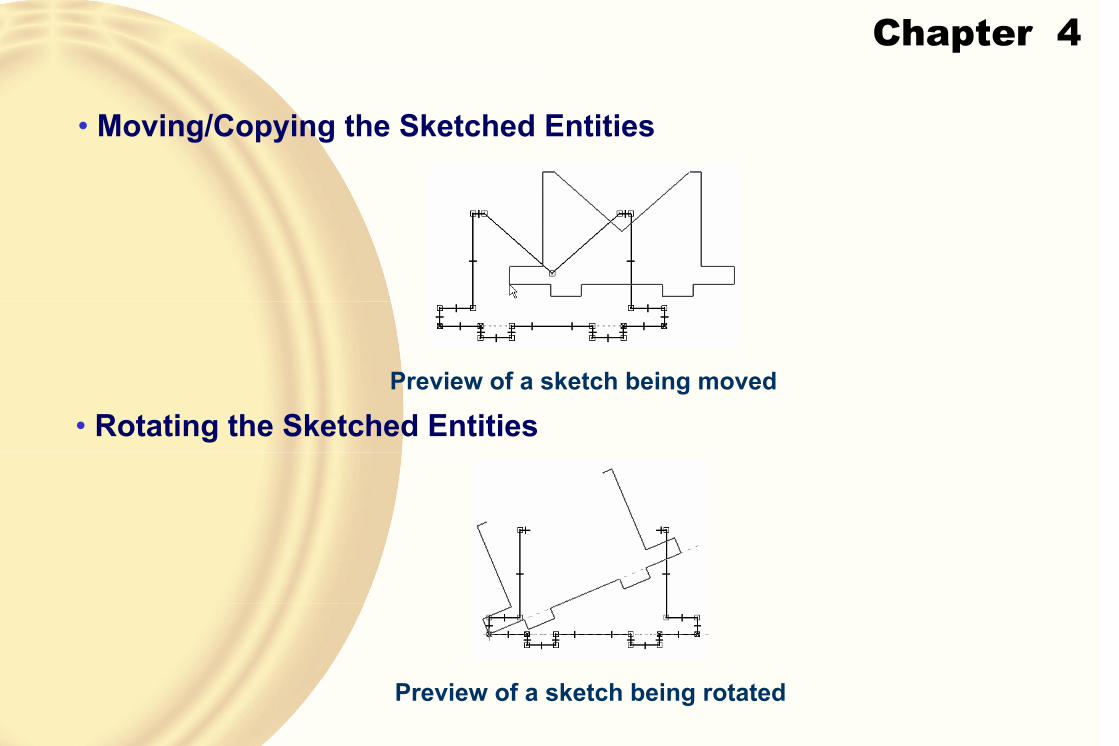
• Moving/Copying the Sketched Entities
Preview of a sketch being moved
• Rotating the Sketched Entities
Preview of a sketch being rotated

Chapter 4
• Mirroring the Sketched Entities
Entities selected to mirror Resulting mirrored sketch
• Scaling the Sketched Entities
Preview of a sketch being scaled
Chapter 4
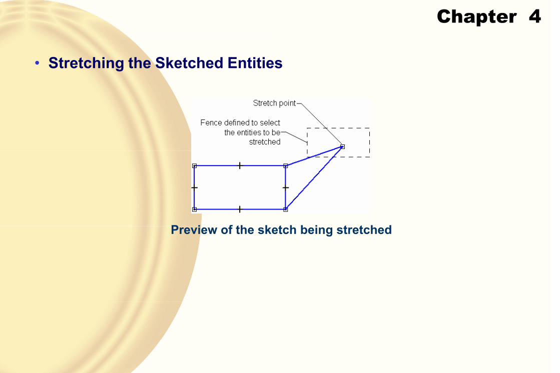
• Stretching the Sketched Entities
Preview of the sketch being stretched

Chapter 4
• Editing the Sketched Entities by DraggingYou can also edit the sketched entities by dragging them.
Depending on the type of entity selected, and the point of selection, the object will be moved or stretched.

Chapter 4
� WRITING TEXT IN THE SKETCHING ENVIRONMENTSolid Edge allows you to write a text in the sketching environment and use it to create features at a later stage.
When you invoke the Text Profile tool, the Text step is active and the Text dialog box will be displayed, as shown in the Figure A.
Figure A The Text dialog box Text along a circle

Chapter 4
� INSERTING IMAGES IN THE SKETCHESTo insert the image, invoke the Image tool from the menu bar.
The Insert Image dialog box will be displayed, as shown in the figure.
The General tab of the Insert Image dialog box
Chapter 4
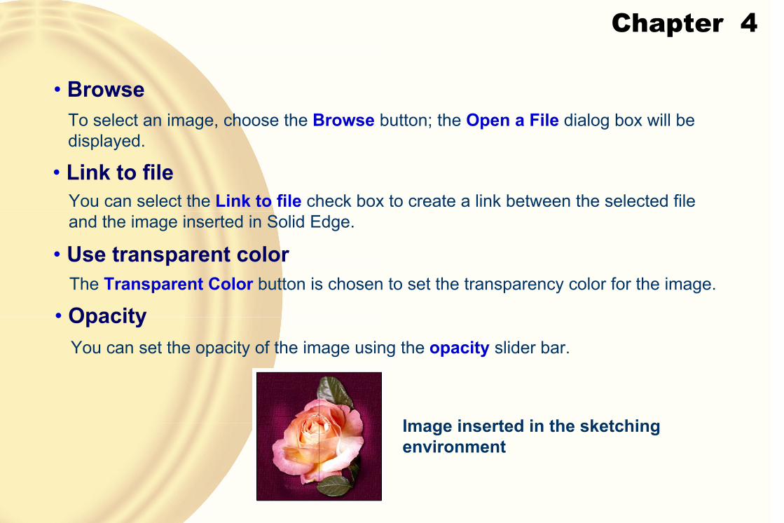
• Browse
• Use transparent color
• Link to file
To select an image, choose the Browse button; the Open a File dialog box will be displayed.
You can select the Link to file check box to create a link between the selected file and the image inserted in Solid Edge.
• OpacityThe Transparent Color button is chosen to set the transparency color for the image.
You can set the opacity of the image using the opacity slider bar.
Image inserted in the sketching environment

Chapter 4
• Border TabThe options in the Border tab, shown in the figure, are used to specify the border for the selected image.
The Border tab of the Insert Imagedialog box

Chapter 4
� CONVERTING SKETCHES INTO BASE FEATURESMost of the designs are a combination of various sketched, placed, and reference features.
After finishing drawing and dimensioning a sketch, you need to convert it into the base feature.
The base features are created in the Part environment.
This environment is invoked when you choose Finish from the ribbon bar.

Chapter 4
� CREATING BASE FEATURES BY PROTRUSION
Profile for the protrusion feature Resulting protrusion feature
Chapter 4
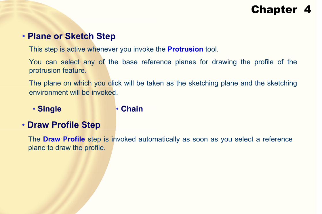
• Plane or Sketch StepThis step is active whenever you invoke the Protrusion tool.
You can select any of the base reference planes for drawing the profile of the protrusion feature.
The plane on which you click will be taken as the sketching plane and the sketching environment will be invoked.
• Single • Chain
• Draw Profile StepThe Draw Profile step is invoked automatically as soon as you select a referenceplane to draw the profile.

Chapter 4
• Extent StepThe Extent step is automatically invoked when you exit the sketching environment after creating the profile or when you choose the Accept button after selecting the profile.
• 1-Direction ExtrudeThe options available in the ribbon bar under this step are:
Preview of the protrusion feature being created by extruding in one direction

Chapter 4
• Non-symmetric ExtentThe Non-symmetric Extent button is chosen to extrude the profile nonsymmetrically on both sides of the plane on which the profile is created, or in other words, to specify different depths of extrusion on both sides.
• Direction 1 • Direction 2
• Symmetric Extent
Preview of the protrusion feature being created with symmetric extent

Chapter 4
• Finite ExtentThis button is chosen by default to specify the depth of the protrusion feature by specifying its numeric value.
• DistanceThe Distance edit box is used to specify the numeric value of the depth of the protrusion feature.
• StepWhile defining the depth of the protrusion feature by moving the cursor on the screen, the value in the Distance edit box increases or decreases in a predefined increment.
This value is specified in the Step edit box.

Chapter 4
� CREATING BASE FEATURES USING THE REVOLVED PROTRUSION
Profile for the revolve protrusion
Resulting revolved protrusion

Chapter 4
• Plane or Sketch StepThis step is active whenever you invoke the Revolved Protrusion tool.
• Draw Profile StepThe Draw Profile step is automatically invoked as soon as you select a reference plane to draw the profile of the revolved feature.
• Extent StepThe Extent step is automatically invoked when you exit the sketching environment after creating the profile or after selecting the axis of revolution of the existing sketch.
• 1-Direction RevolveThis option is invoked by default and allows you to revolve the profile in one of the directions of the sketching plane.

Chapter 4
• Symmetric ExtentThe Symmetric Revolve button is chosen to revolve the profile symmetrically on both sides of the plane on which the profile is drawn.
• Non-symmetric ExtentThe Non-symmetric Extent button is chosen to revolve the profile nonsymmetrically on both sides of the plane on which the profile is created, or in other words, to specify different angles of revolution on both sides.
• Revolve 360°This button is chosen to revolve the profile through 360-degree.
• Finite ExtentThis button is chosen by default to create the revolved feature and is used to revolve the profile through a specified angle.

Chapter 4
• Angle
180-degree revolved protrusion in one direction
180-degree revolved protrusion in the other direction
• Step
This edit box is used to specify the value by which the angle value will be increased or decreased when you move the cursor in the drawing window to define the angle of revolution.

Chapter 4
� ROTATING THE VIEW OF A MODEL IN 3D SPACESolid Edge provides you with an option of rotating the view of a solid model freely in three-dimensional (3D) space.
To invoke this option, choose the Rotate button from the Main toolbar.
When you choose the Rotate button, a 3D indicator with three axes and the origin will be displayed at the center of the current view.
This 3D indicator is called the Rotate tool.
Chapter 4
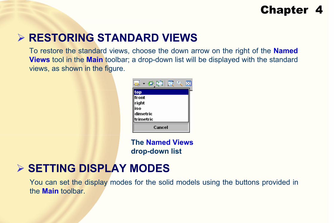
� RESTORING STANDARD VIEWSTo restore the standard views, choose the down arrow on the right of the NamedViews tool in the Main toolbar; a drop-down list will be displayed with the standard views, as shown in the figure.
The Named Viewsdrop-down list
� SETTING DISPLAY MODESYou can set the display modes for the solid models using the buttons provided in the Main toolbar.
Chapter 4
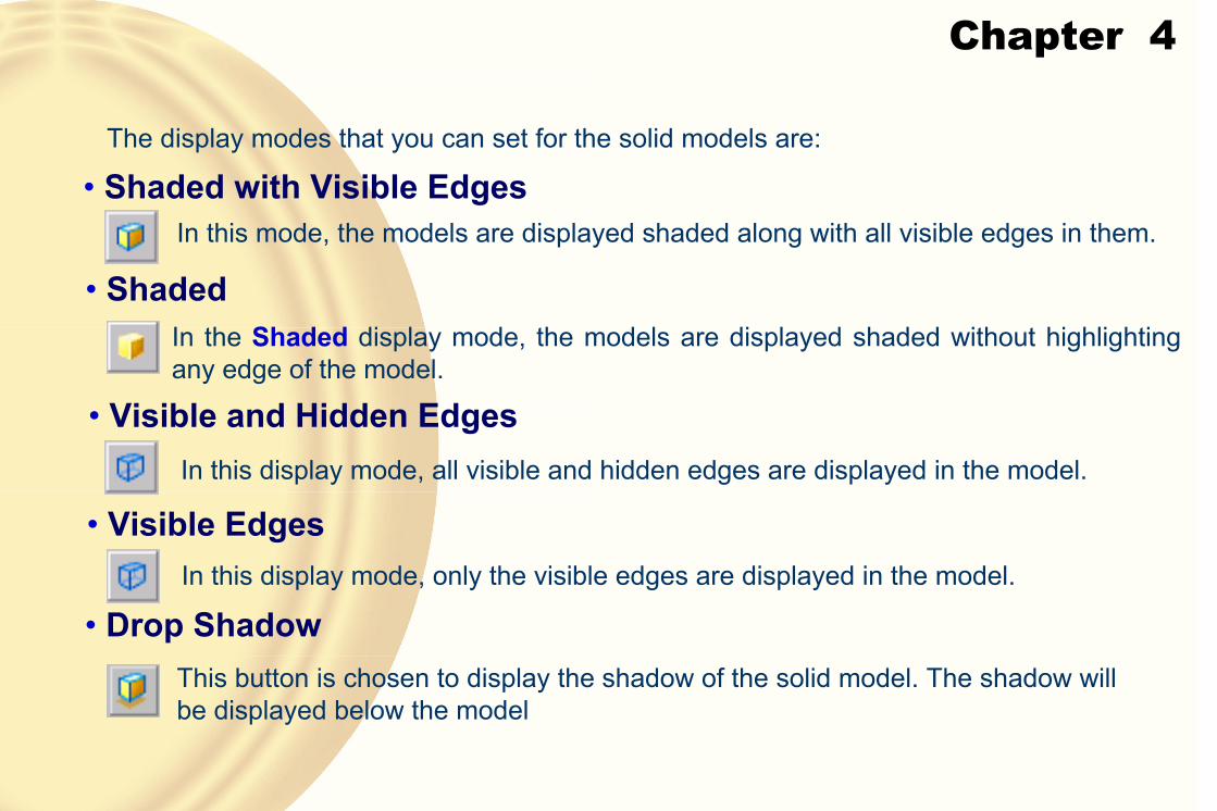
The display modes that you can set for the solid models are:
• Shaded with Visible EdgesIn this mode, the models are displayed shaded along with all visible edges in them.
• ShadedIn the Shaded display mode, the models are displayed shaded without highlighting any edge of the model.
• Visible and Hidden EdgesIn this display mode, all visible and hidden edges are displayed in the model.
• Visible EdgesIn this display mode, only the visible edges are displayed in the model.
• Drop ShadowThis button is chosen to display the shadow of the solid model. The shadow will be displayed below the model

Chapter 4
� IMPROVING THE DISPLAY QUALITY OF THE MODELIn Solid Edge, you can modify the display quality of the model by improving its sharpness.
To modify the sharpness, choose the down arrow on the right of the Sharpenbutton in the Main toolbar.
From this drop-down list, select the type of sharpness.
Chapter 4
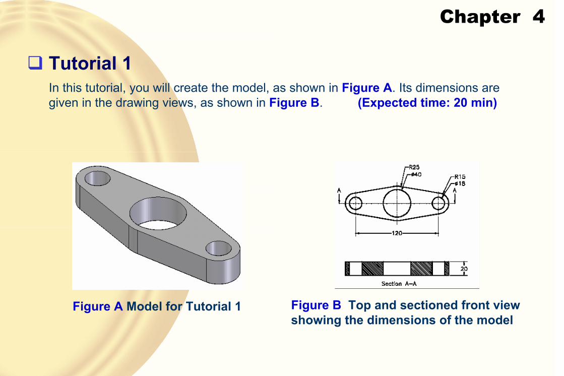
� Tutorial 1In this tutorial, you will create the model, as shown in Figure A. Its dimensions are given in the drawing views, as shown in Figure B. (Expected time: 20 min)
Figure A Model for Tutorial 1 Figure B Top and sectioned front view showing the dimensions of the model
Chapter 4
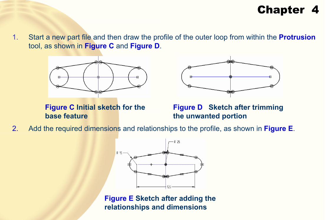
1. Start a new part file and then draw the profile of the outer loop from within the Protrusiontool, as shown in Figure C and Figure D.
Figure C Initial sketch for the base feature
Figure D Sketch after trimming the unwanted portion
2. Add the required dimensions and relationships to the profile, as shown in Figure E.
Figure E Sketch after adding the relationships and dimensions
Chapter 4
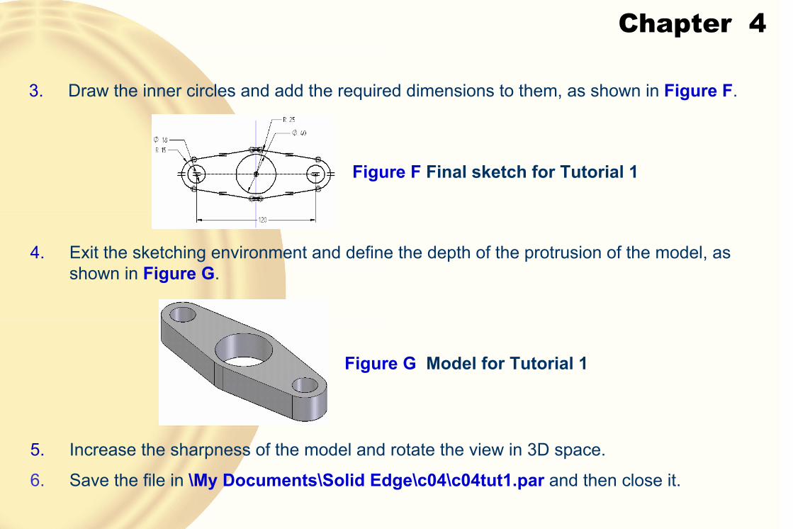
3. Draw the inner circles and add the required dimensions to them, as shown in Figure F.
Figure F Final sketch for Tutorial 1
4. Exit the sketching environment and define the depth of the protrusion of the model, as shown in Figure G.
Figure G Model for Tutorial 1
5. Increase the sharpness of the model and rotate the view in 3D space.
6. Save the file in \My Documents\Solid Edge\c04\c04tut1.par and then close it.
Chapter 4
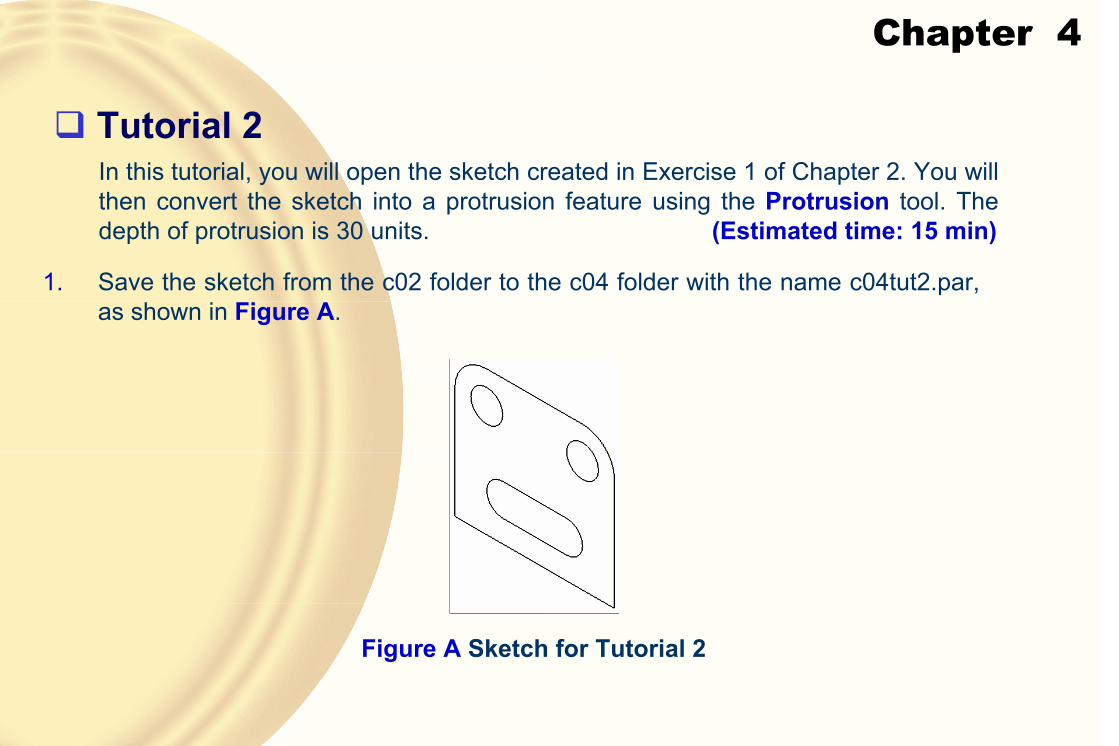
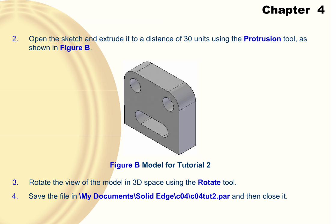
� Tutorial 2In this tutorial, you will open the sketch created in Exercise 1 of Chapter 2. You will then convert the sketch into a protrusion feature using the Protrusion tool. The depth of protrusion is 30 units. (Estimated time: 15 min)
1. Save the sketch from the c02 folder to the c04 folder with the name c04tut2.par, as shown in Figure A.
Figure A Sketch for Tutorial 2
Chapter 4
2. Open the sketch and extrude it to a distance of 30 units using the Protrusion tool, as shown in Figure B.
Figure B Model for Tutorial 2
3. Rotate the view of the model in 3D space using the Rotate tool.
4. Save the file in \My Documents\Solid Edge\c04\c04tut2.par and then close it.

Chapter 4
� Tutorial 3In this tutorial, you will open the sketch created in Tutorial 2 of Chapter 2. You will then convert the sketch into a revolved feature using the Revolved Protrusion tool.
(Estimated time: 15 min)
1. Save the sketch from the c02 folder to the c04 folder with the name c04tut3.par.
Figure A Sketch for the revolved model

Chapter 4
2. Open the sketch and revolve it using the Revolved Protrusion tool, as shown in Figure B.
Figure B Revolved model for Tutorial 3
3. Rotate the model in 3D space using the Rotate tool.
4. Save the file in \My Documents\Solid Edge\c04\c04tut3.par and then close it.

Chapter 4
� Exercise 1Open the profile drawn in Exercise 2 of Chapter 2 and convert it into a protrusion feature. The depth of protrusion is 40 units. After creating the model, use the Rotate tool to rotate the view of the model. Before saving and closing the file, restore the isometric view of the model. (Expected time: 15 min)
� Exercise 2Open the profile drawn in Tutorial 1 of Chapter 2 and convert it into a protrusion feature. The depth of protrusion is 40 units. After creating the model, use the Rotate tool to rotate the view of the model. Before saving and closing the file, restore the isometric view of the model. (Expected time: 15 min)

Chapter 5
• Understand the use of reference geometries
• Create reference planes
• Control the display of reference axes
• Create new coordinate systems
• Use additional termination options to create protrusion features
• Create protruded and revolved cutouts
• Include edges of the existing features as sketched entities in the current sketch
• Work with advanced drawing display tools
Learning Objectives:
Chapter 5
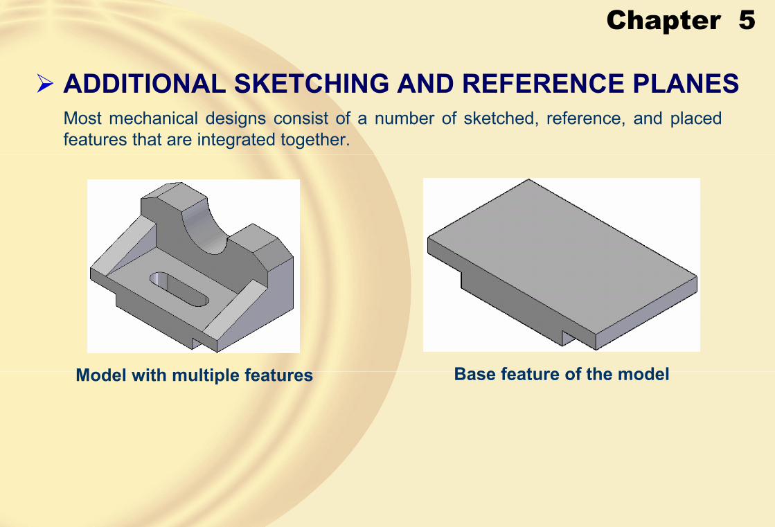
� ADDITIONAL SKETCHING AND REFERENCE PLANESMost mechanical designs consist of a number of sketched, reference, and placed features that are integrated together.
Model with multiple features Base feature of the model

Chapter 5
Various features in the model
• Local Reference PlanesLocal reference planes are the ones that are created while defining a feature.
• Global Reference PlanesGlobal reference planes are the ones that are created separately as a feature using the tools available in the Features toolbar.

Chapter 5
� CREATING REFERENCE PLANES• Creating Coincident Plane
Creating a coincident plane with the bottom edge defining the orientation of the X axis
Creating a coincident plane with the inclined edge defining the orientation of the X axis
Preview of the reference plane after reversing thepositive X axis direction

Chapter 5
• Creating Parallel Plane
Using the center point in the model to define the location of the parallel plane
Using the tangent point in the model to define the location of the parallel plane
Chapter 5
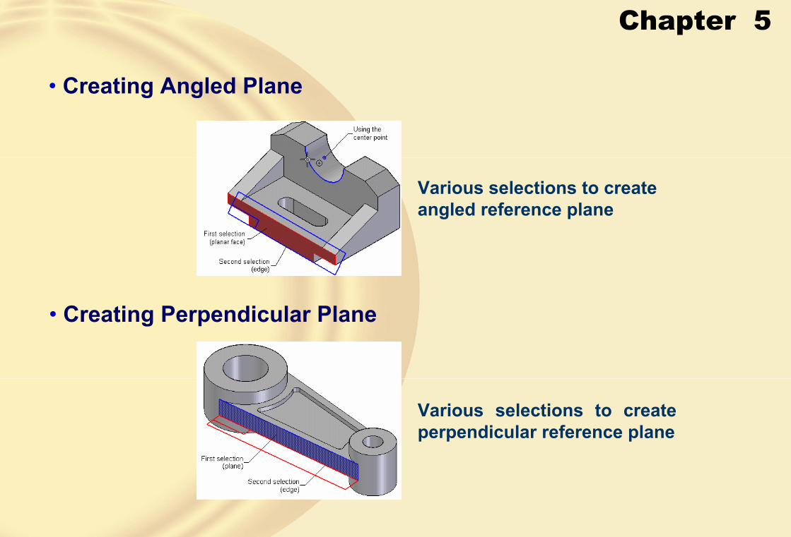
• Creating Angled Plane
• Creating Perpendicular Plane
Various selections to create angled reference plane
Various selections to create perpendicular reference plane

Chapter 5
• Creating Coincident Plane by AxisThe Coincident Plane By Axis tool works in the same way as the Coincident Planetool.
The only difference is that in this tool, after selecting the plane, you will also be prompted to select the edge to define the direction of the positive X axis and the orientation of the plane.
• Creating a Plane Normal to an Edge or a Sketched Curve
Creating a plane normal to a sketched curve

Chapter 5
• Creating a Plane Using Three Points
Creating a plane using three points
• Displaying the Reference AxesSolid Edge automatically creates reference axes when you create a revolved feature, hole feature, or any other circular or semicircular feature.
Chapter 5
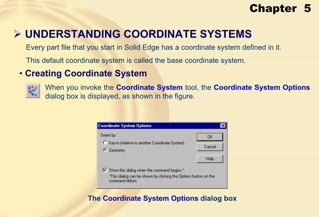
� UNDERSTANDING COORDINATE SYSTEMSEvery part file that you start in Solid Edge has a coordinate system defined in it.
This default coordinate system is called the base coordinate system.
• Creating Coordinate SystemWhen you invoke the Coordinate System tool, the Coordinate System Options dialog box is displayed, as shown in the figure.
The Coordinate System Options dialog box
Chapter 5
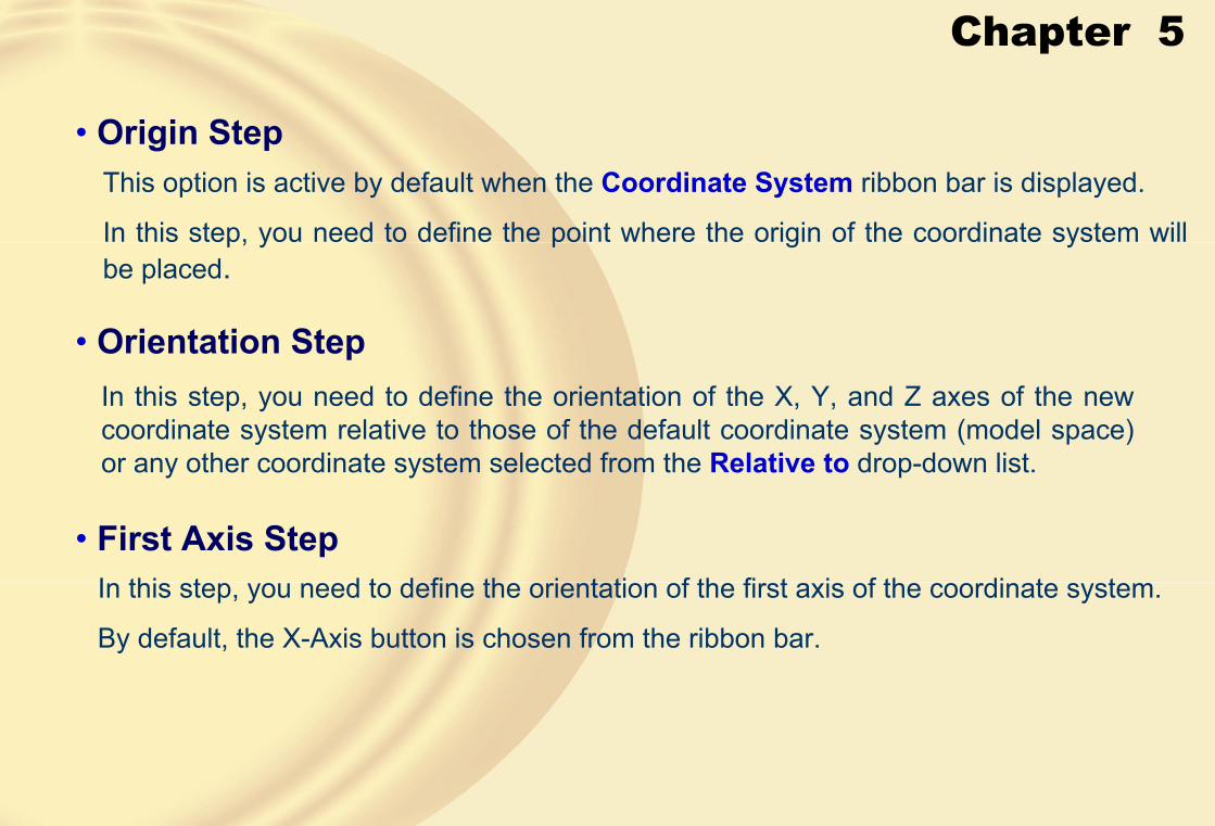
• Origin StepThis option is active by default when the Coordinate System ribbon bar is displayed.
In this step, you need to define the point where the origin of the coordinate system will be placed.
• Orientation StepIn this step, you need to define the orientation of the X, Y, and Z axes of the new coordinate system relative to those of the default coordinate system (model space) or any other coordinate system selected from the Relative to drop-down list.
• First Axis StepIn this step, you need to define the orientation of the first axis of the coordinate system.
By default, the X-Axis button is chosen from the ribbon bar.
Chapter 5
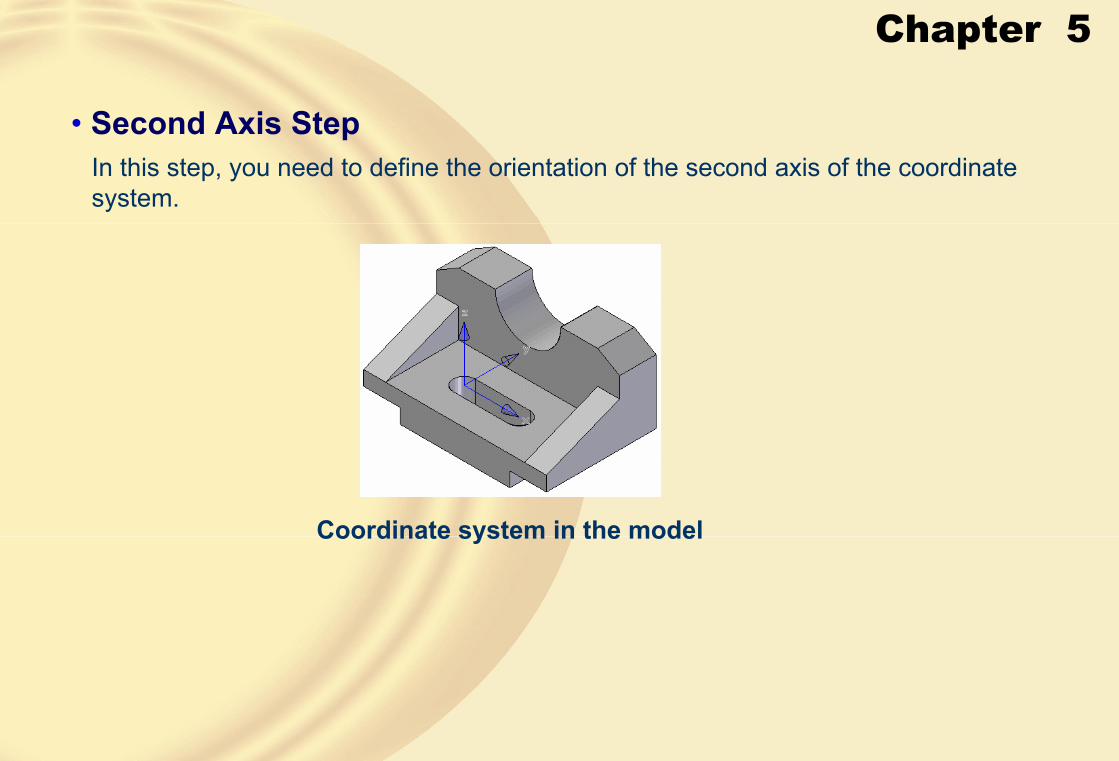
• Second Axis StepIn this step, you need to define the orientation of the second axis of the coordinate system.
Coordinate system in the model
Chapter 5
� USING THE OTHER OPTIONS OF THE PROTRUSION TOOL
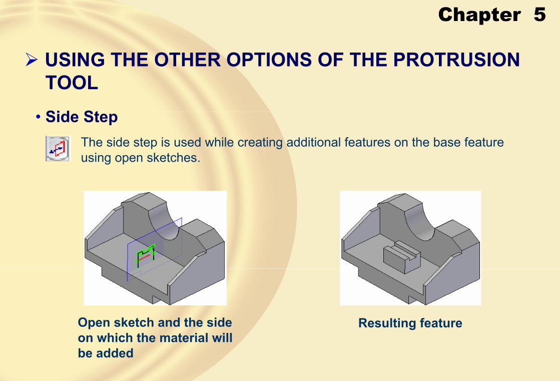
• Side Step
Open sketch and the side on which the material will be added
Resulting feature
The side step is used while creating additional features on the base feature using open sketches.
Chapter 5
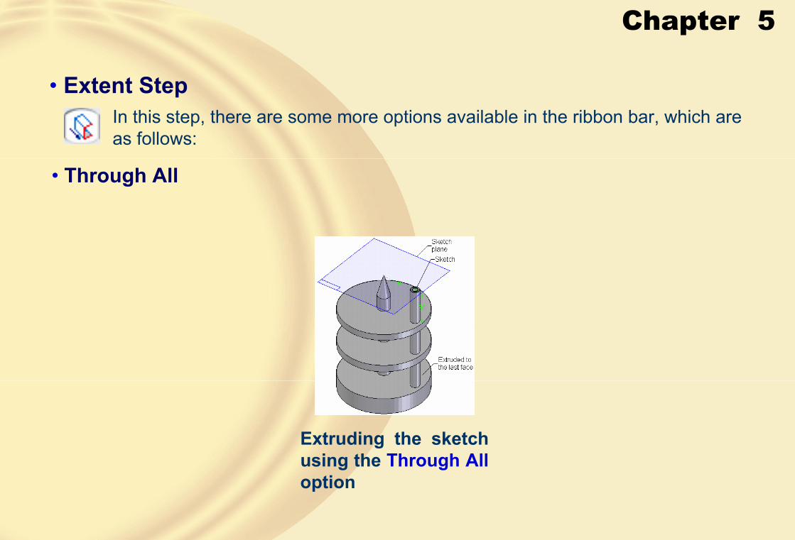
• Extent StepIn this step, there are some more options available in the ribbon bar, which are as follows:
• Through All
Extruding the sketch using the Through Alloption

Chapter 5
• Through Next
Extruding the sketch using the Through Next option
• From/To Extent
Extruding the sketch using the From/To Extent option
Creating a protrusion feature by defining offset values for the “from” and “to” surfaces

Chapter 5
• Treatment Step
Sketch extruded using the Through Alloption on both sides of the sketching plane with the Non-symmetric Extentoption
In this step, you can add a draft or crown to the protrusion feature.

Chapter 5
Different drafts applied to both sides of a protrusion feature
Different crowns applied to both sides of a protrusion feature
Chapter 5
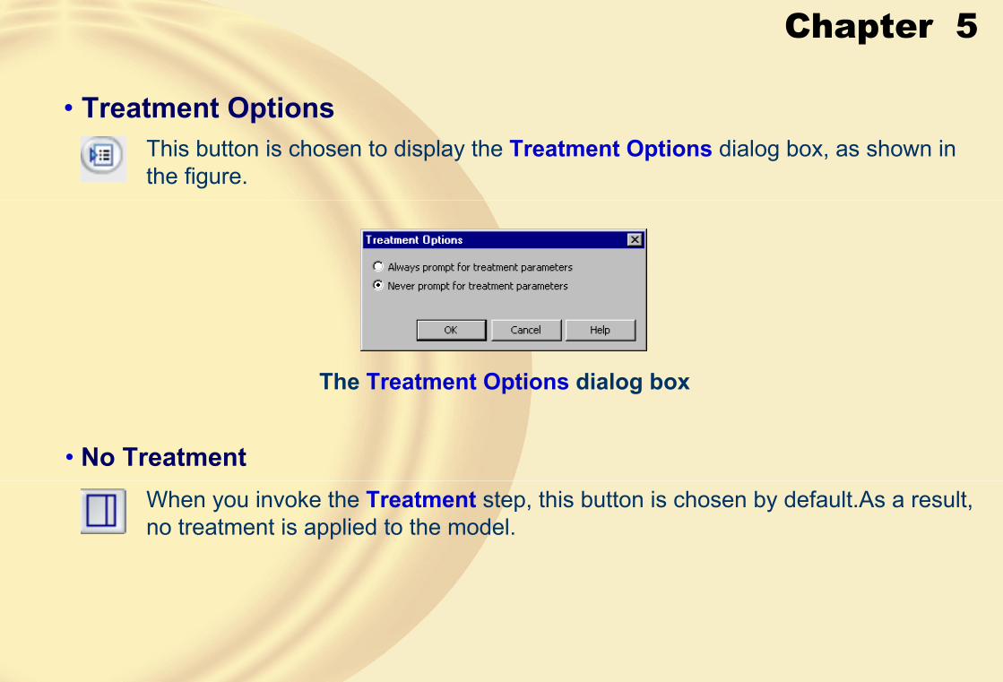
• Treatment OptionsThis button is chosen to display the Treatment Options dialog box, as shown in the figure.
The Treatment Options dialog box
• No TreatmentWhen you invoke the Treatment step, this button is chosen by default.As a result, no treatment is applied to the model.

Chapter 5
• Draft
The Draft button is chosen to add a draft to the protrusion feature.
• CrownThe Crown button is chosen to add a crown to the protrusion feature.
When you choose this button, the Crown Parameters dialog box will be displayed.
The Crown Parametersdialog box

Chapter 5
• Crown TypeThe Crown Type drop-down list is used to select the technique of applying a crown to the feature.
The options available in this drop-down list are:
• No Crown
• Radius
• Radius and take-off
• Offset
• Offset and take-off
• Radius
The Radius edit box is used to specify the radius value of the crown and will be available only when you select the Radius or the Radius and take-off crown type.
• OffsetThe Offset edit box is used to specify the offset value of the crown and will be available only when you select the Offset or the Offset and take-off crown type.

Chapter 5
• TakeoffThe Takeoff edit box is used to specify the takeoff value of the crown and will be available only when you select the Radius and take-off or the Offset and take-offcrown type.
• Flip Side
The Flip Side button is used to reverse the side on which the crown is applied.
• Flip Curvature
The Flip Curvature button is used to reverse the curvature of the crown.
• Preview Window
The Preview window displays the preview of various crown parameters that you define using the Crown Parameters dialog box.

Chapter 5
Preview of the crown showing the side of the crown
Feature with the resulting crown
Preview of the crown showing the side of the crown
Feature with the resulting crown

Chapter 5
The Crown Parameters button is chosen to redisplay the Crown Parameters dialog box for modifying the crown parameters.
� CREATING CUTOUT FEATURESCutouts are created by removing the material, defined by a profile, from one or more existing features.
In Solid Edge, you can create various types of cutouts such as extruded cutouts, revolved cutouts, swept cutouts, and so on.
• Crown Parameters

Chapter 5
• Creating Extruded Cutouts
Base feature and the sketch for the cutout
Rotated view of the model after creating the cutout
Chapter 5
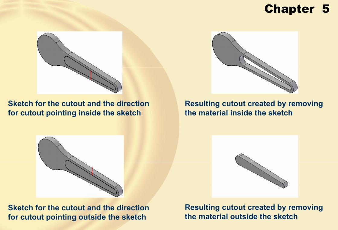
Sketch for the cutout and the direction for cutout pointing inside the sketch
Resulting cutout created by removing the material inside the sketch
Sketch for the cutout and the direction for cutout pointing outside the sketch
Resulting cutout created by removing the material outside the sketch

Chapter 5
Open profile and the side of material removal
Resulting cutout created by removing the material above the open profile
Open profile and the side of material removal
Resulting cutout created by removing the material below the open profile
Chapter 5
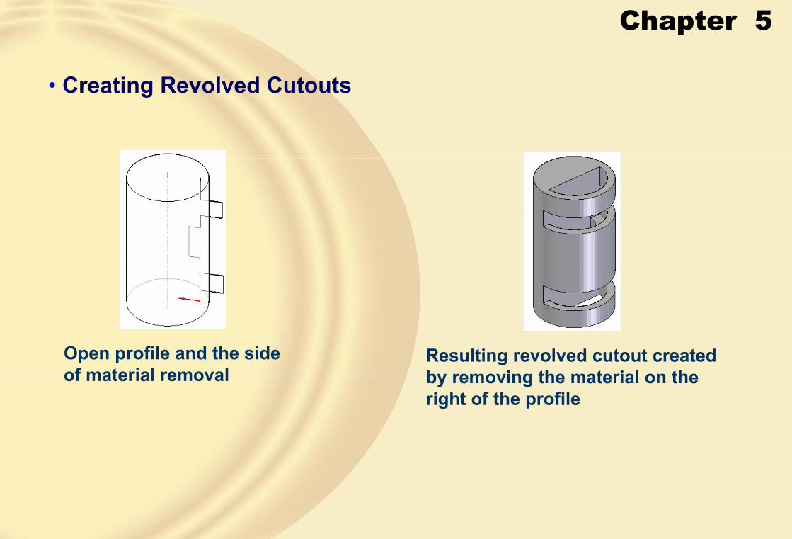
• Creating Revolved Cutouts
Open profile and the side of material removal
Resulting revolved cutout created by removing the material on the right of the profile

Chapter 5
Open profile and the side of material removal
Resulting revolved cutout created by removing the material on the right of the profile

Chapter 5
� INCLUDING THE EDGES OF THE EXISTING FEATURES IN THE SKETCHChoose the Include button from the Draw toolbar to display the Include Optionsdialog box, as shown in the figure.
The Include Options dialog box
Chapter 5
• Include with offsetThis check box is selected to project the geometries with some offset value.
• Include internal face loopIf this check box is selected, the geometries of all internal loops on a face will also be projected when you select a face to project the edges.
• Assembly Part Include Options AreaThe options available in this area are used in the assembly modeling environment.
• Allow locate of Peer Parts and Assembly Sketches
• Make included geometry associative
• Select Step
• Offset Step

Chapter 5
� ADVANCED DRAWING DISPLAY TOOLS• Creating User-defined Named Views
You can use the Named Views drop-down list in the Main toolbar to invoke the standard named views.
In Solid Edge, you can also create user-defined standard views that are automatically added to the Named Views drop-down list.
• Using the Common ViewsSolid Edge provides you with a very user-friendly tool called Common Views to set the current view to some standard common views.
Chapter 5
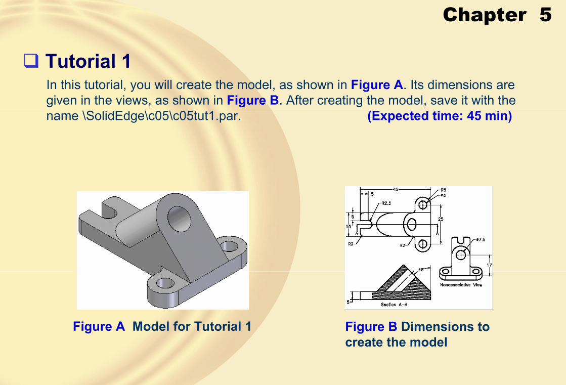
� Tutorial 1In this tutorial, you will create the model, as shown in Figure A. Its dimensions are given in the views, as shown in Figure B. After creating the model, save it with the name \SolidEdge\c05\c05tut1.par. (Expected time: 45 min)
Figure A Model for Tutorial 1 Figure B Dimensions to create the model

Chapter 5
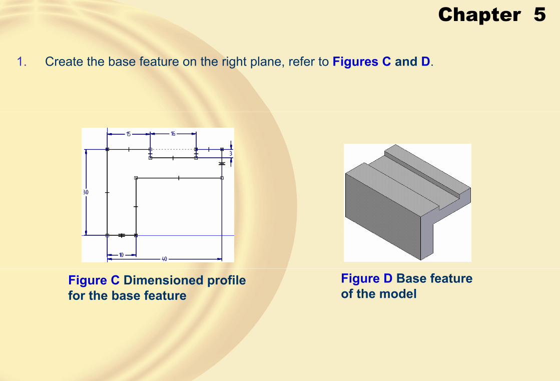
1 Create the base feature with two holes on the top plane, refer to Figures C and D.
Figure D Base feature of the model
Figure C Dimensioned profile for the base feature
Chapter 5
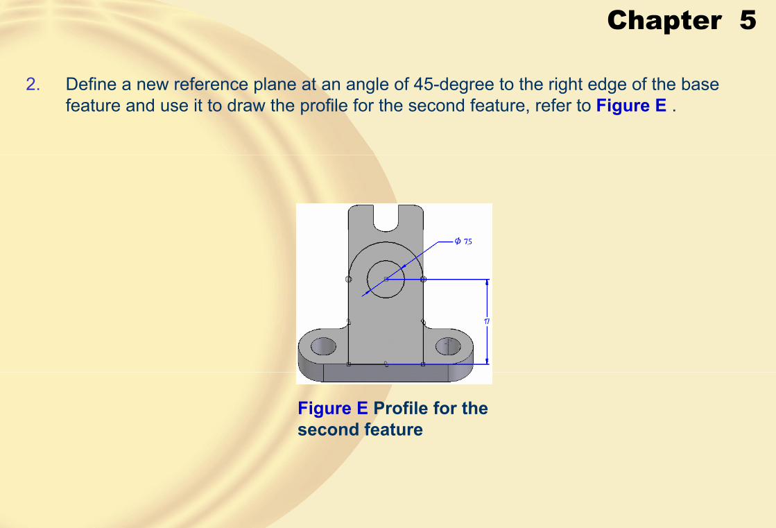
2. Define a new reference plane at an angle of 45-degree to the right edge of the base feature and use it to draw the profile for the second feature, refer to Figure E .
Figure E Profile for the second feature
Chapter 5
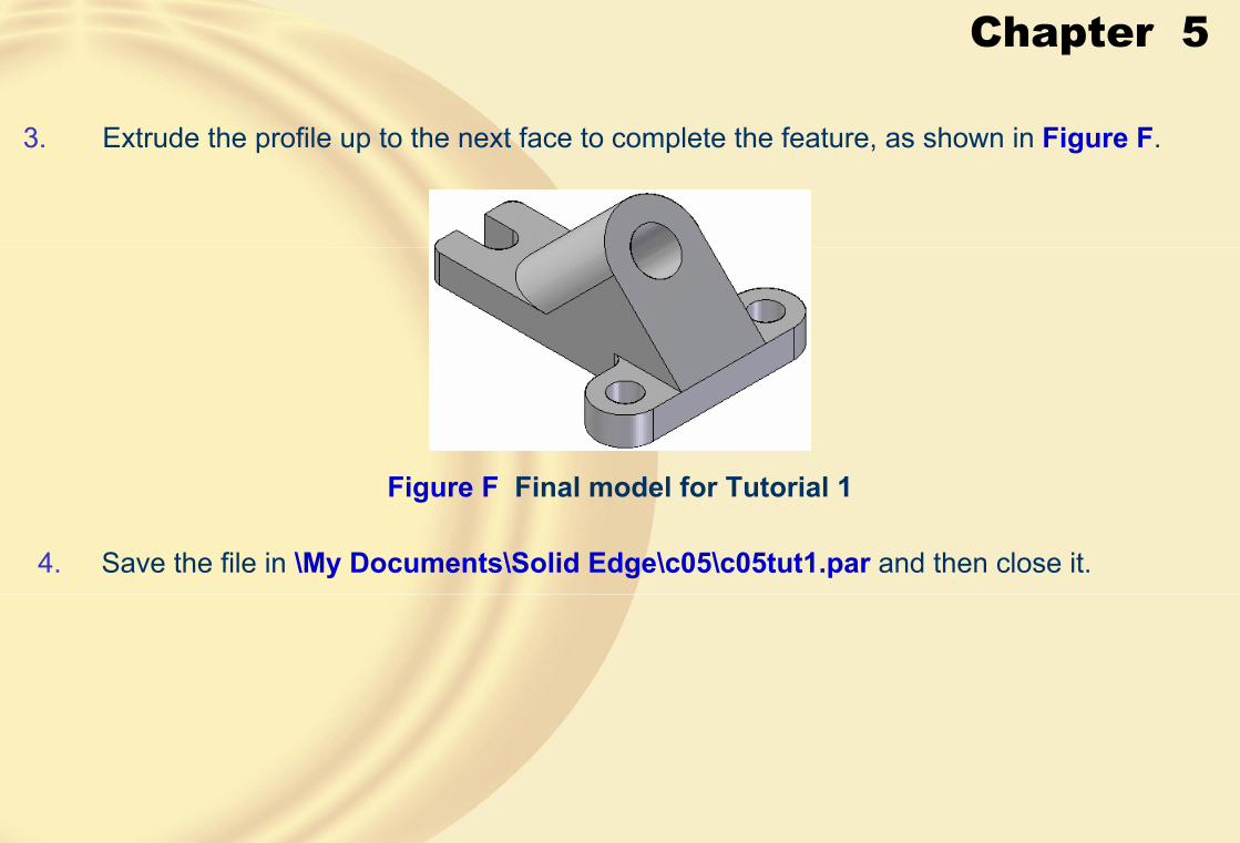
3. Extrude the profile up to the next face to complete the feature, as shown in Figure F.
Figure F Final model for Tutorial 1
4. Save the file in \My Documents\Solid Edge\c05\c05tut1.par and then close it.

Chapter 5
� Tutorial 2In this tutorial, you will create the model, as shown in Figure A. Its dimensions are given in the views, as shown in Figure B. After creating the model, save it with the name \SolidEdge\c05\c05tut2.par. (Expected time: 45 min)
Figure A Model for Tutorial 2 Figure B Dimensions of the model
Chapter 5
1. Create the base feature on the right plane, refer to Figures C and D.
Figure D Base feature of the model
Figure C Dimensioned profile for the base feature

Chapter 5
2. Select the top planar face of the base feature as the sketching plane and then create the second feature, refer to Figures E and F.
Figure E Open profile for the second feature
Figure F Model after creating the second feature

Chapter 5
3. Define a reference plane at an offset of 10 units from the bottom face of the second feature and use it to create the third feature, as shown in Figure G.
Figure G Model after creating the third feature

Chapter 5
4. Create two holes on the left face of the base feature using the Cutout tool, as shown in Figure H and Figure I.
Figure H Profile for the cutout Figure I Model after creating the cutout

Chapter 5
5. Similarly, create the remaining cutouts to complete the model, as shown in Figure J.
Figure J Final model for Tutorial 2
6. Save the file in \My Documents\Solid Edge\c05\c05tut2.par and then close it.

Chapter 5
� Tutorial 3In this tutorial, you will create the model, as shown in Figure A. Its dimensions are given in the views, as shown in Figure B. After creating the model, save it with the name \SolidEdge\c05\c05tut3.par. (Expected time: 45 min)
Figure A Model for Tutorial 3 Figure B Views and dimensions for Tutorial 3

Chapter 5
1 Create the base feature on the top plane, as shown in Figures C and Figure D.
Figure C Profile for the base feature Figure D Base feature of the model

Chapter 5
2. Create the second feature also on the top plane, refer to Figures E and F.
Figure E Sketch of the second feature
Figure F Model after creating the feature
Chapter 5
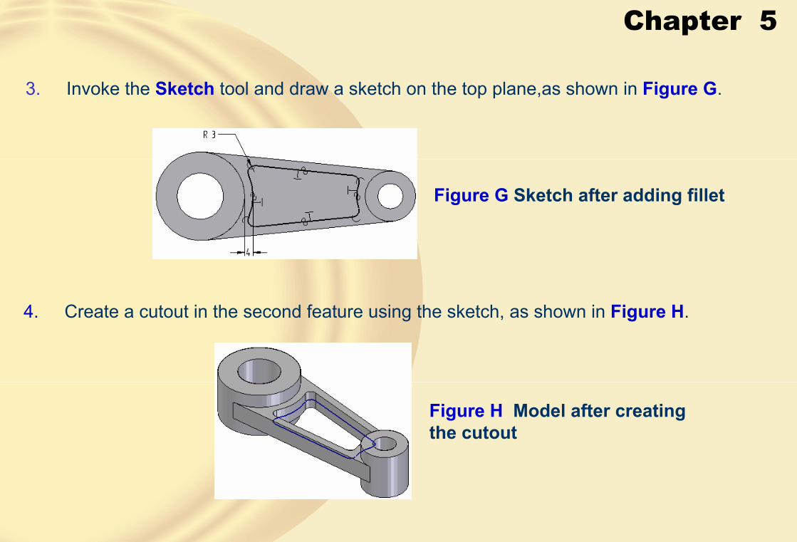
3. Invoke the Sketch tool and draw a sketch on the top plane,as shown in Figure G.
Figure G Sketch after adding fillet
4. Create a cutout in the second feature using the sketch, as shown in Figure H.
Figure H Model after creating the cutout
Chapter 5
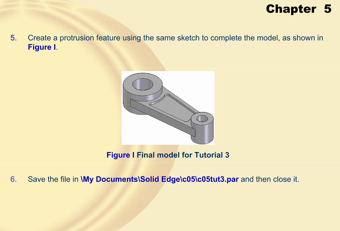
5. Create a protrusion feature using the same sketch to complete the model, as shown in Figure I.
Figure I Final model for Tutorial 3
6. Save the file in \My Documents\Solid Edge\c05\c05tut3.par and then close it.
Chapter 5
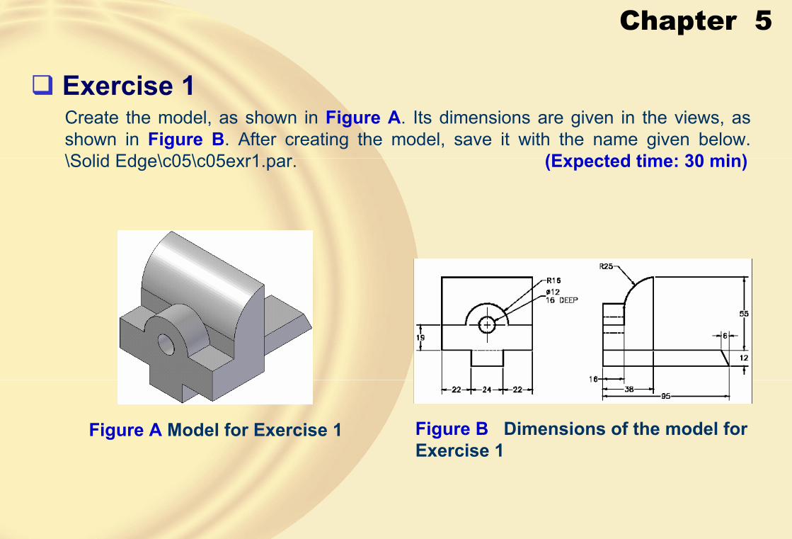
� Exercise 1Create the model, as shown in Figure A. Its dimensions are given in the views, as shown in Figure B. After creating the model, save it with the name given below.\Solid Edge\c05\c05exr1.par. (Expected time: 30 min)
Figure A Model for Exercise 1 Figure B Dimensions of the model for Exercise 1

Chapter 5
� Exercise 2Create the model, as shown in Figure A. Its dimensions are given in the views, as shown in Figure B. After creating the model, save it with the name given below.\Solid Edge\c05\c05exr2.par (Expected time: 30 min)
Figure A Model for Exercise 2 Figure B Model for Exercise 2
Chapter 6
Learning Objectives:• Use the Hole tool for creating various types of holes
• Fillet edges of a model
• Chamfer edges of a model
• Mirror features and solid bodies
• Create rectangular patterns of features
• Create circular patterns of features
• Create rib features

Chapter 6
� ADVANCED MODELING TOOLSThe advanced modeling tools appreciably reduce the time taken in creating the features in the models, thus reducing the designing time.
� CREATING HOLESTo specify the hole options, choose the Hole Options button from the ribbon bar; the Hole Options dialog box will be displayed, as shown in the figure.
The Hole Options dialog box

Chapter 6
The options available in the Hole Options dialog box are:
• Saved settingsThis drop-down list is used to select the saved hole settings.
By default, this drop-down list does not have any option.
• SaveThis button is chosen to save the hole settings with some name.
• DeleteThis button is chosen to delete the saved hole setting that is current in the Savedsettings drop-down list.
• TypeThis drop-down list is used to specify the type of hole that you want to create.

Chapter 6
• SimpleThis option is selected to create a simple hole.
Section view of a simple hole
• ThreadedThis option is selected to create a threaded hole.
• TaperedThis option is selected to create a tapered hole.
Section view of a tapered hole
Chapter 6
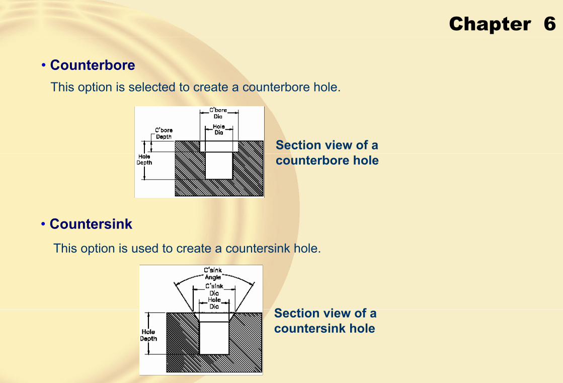
• CounterboreThis option is selected to create a counterbore hole.
Section view of a counterbore hole
• CountersinkThis option is used to create a countersink hole.
Section view of a countersink hole

Chapter 6
• UnitThis drop-down list is used to specify the units for creating a hole.
• Settings Area Options (For Simple Hole)The remaining options in the Settings area depend on the type of hole selected from the Type drop-down list.
• Diameter• Settings Area Options (For Threaded Hole)In addition to the Diameter drop-down list, the following options are provided by the Settings area:
• Thread
• To hole extent
• Finite extent

Chapter 6
• Settings Area Options (For Tapered Hole)In addition to the Diameter drop-down list, the following options are provided by the Settings area:
• Profile at bottom
• Profile at top
• Decimal (R/L)
• Ratio (R:L)
• Angle
• Settings Area Options (For Counterbore Hole)In addition to the Diameter drop-down list, the following options are provided by the Settings area for the counterbore hole type:
• Profile at top
• Profile at bottom
• Counterbore diameter
• Counterbore depth
• V bottom angle
Chapter 6
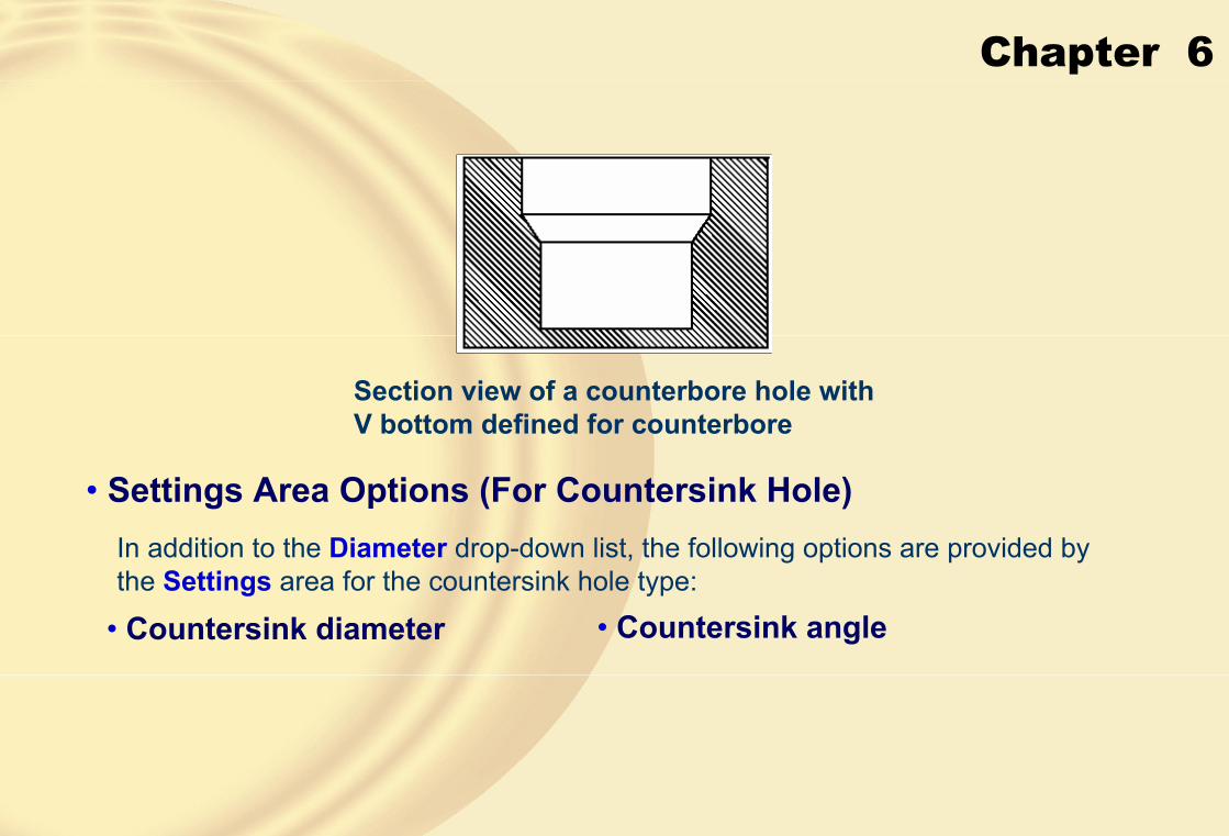
• Settings Area Options (For Countersink Hole)In addition to the Diameter drop-down list, the following options are provided by the Settings area for the countersink hole type:
Section view of a counterbore hole with V bottom defined for counterbore
• Countersink diameter • Countersink angle

Chapter 6
• V bottom angle
Section view of the countersink hole with V bottom
• Dimension to flat
• Dimension to V
• Extents AreaMost of the options available in the Extents area are the standard termination options that are discussed in the Protrusion tool.

Chapter 6
• Plane StepThe Plane step allows you to select the plane on which the profile of the hole will be placed.
• Hole StepThe Hole step will be automatically invoked as soon as you specify the plane to place the hole profile.
Profiles for four counterbore holes placed in the sketching environment
• Extent Step
Model after creating four counterbore holes

Chapter 6
� CREATING ROUNDSIn Solid Edge, you can add fillets or rounds to the sharp edges of the models using the Round tool.
You can select the type of round you want to create from the Round Optionsdialog box, as shown in the figure.
The Round Options dialog box
• Creating Constant Radius RoundTo create this type of round, select the Constant radius option from the RoundOptions dialog box.
The options available in the ribbon bar in this step are:

Chapter 6
• SelectThe Select drop-down list provides various selection types for selecting the entities to fillet.
• Edge/Corner
• Chain
• Face
• Loop
• Feature
• All Fillets
• All Rounds
Round added to the model using the All Fillets option
Round added to the model using the All Rounds option
Chapter 6
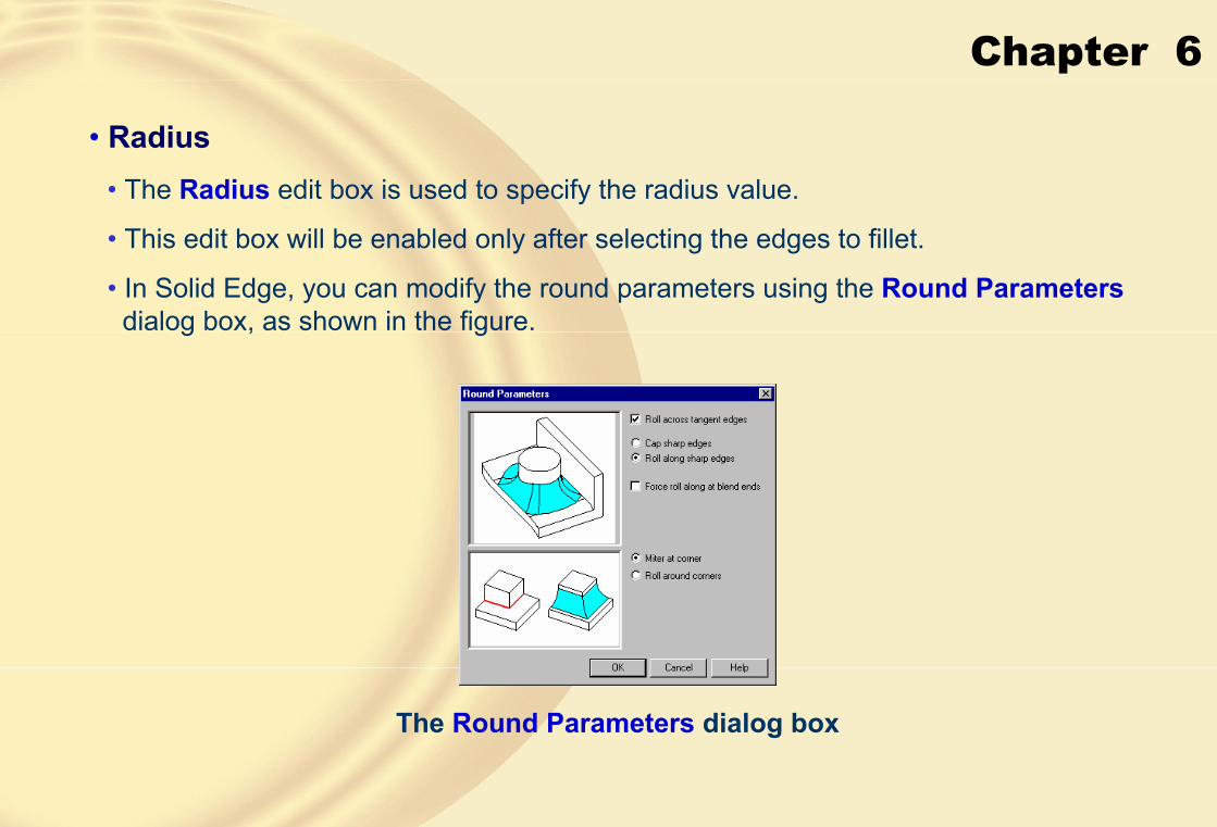
• Radius• The Radius edit box is used to specify the radius value.
• This edit box will be enabled only after selecting the edges to fillet.
• In Solid Edge, you can modify the round parameters using the Round Parametersdialog box, as shown in the figure.
The Round Parameters dialog box

Chapter 6
• Roll across tangent edges
Model before creating the round
Round rolled across the tangent edge
Round terminated at the tangent edge
Chapter 6
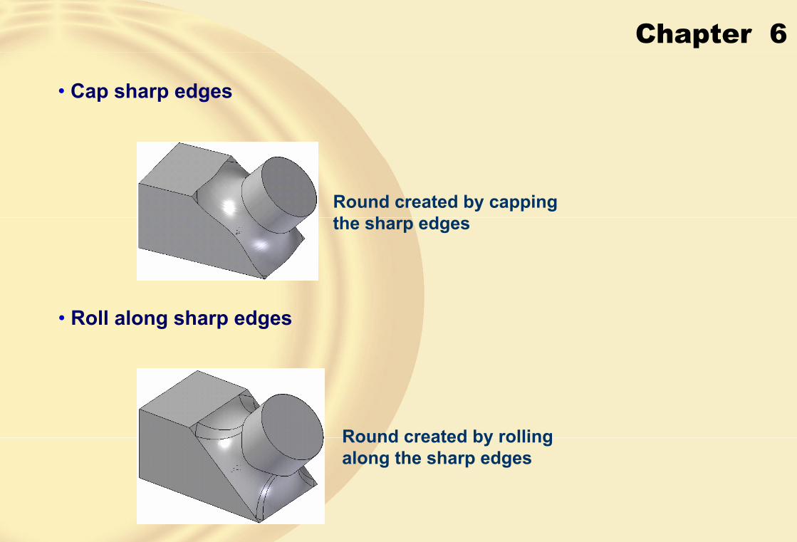
• Cap sharp edges
Round created by capping the sharp edges
• Roll along sharp edges
Round created by rolling along the sharp edges

Chapter 6
• Force roll along at blend endsThis check box is selected to force the round at the blend ends to retain the sharp edges.
• Miter at cornerThis radio button is selected to create a miter at the sharp corner.
• Roll around corner
Edges rounded without setback Edges rounded with setback

Chapter 6
• SelectThis drop-down list enables you to select the corner to soften.
• MethodThis drop-down list is used to specify the method of adding the setback to the corner.
• ValueThis edit box is used to specify the setback value.
• Unique Edge Values
Setback with different values along each edge

Chapter 6
• Creating Variable Radius Round
Variable radius round
� CREATING CHAMFERSChamfering is defined as the process of beveling the sharp edges of a model to reduce the area of stress concentration.
The Chamfer Options dialog box is displayed by choosing the Chamfer Optionsbutton from the ribbon bar.
The Chamfer Optionsdialog box
Chapter 6
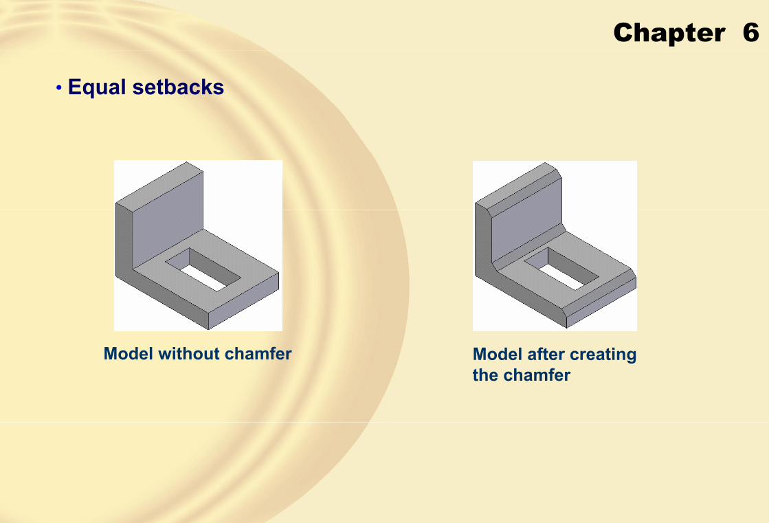
• Equal setbacks
Model without chamfer Model after creating the chamfer

Chapter 6
• Angle and setback
Selecting the face and edge to chamfer
Model after creating the chamfer
• 2 SetbacksThis radio button is selected to create a chamfer using two different distances.
Chapter 6
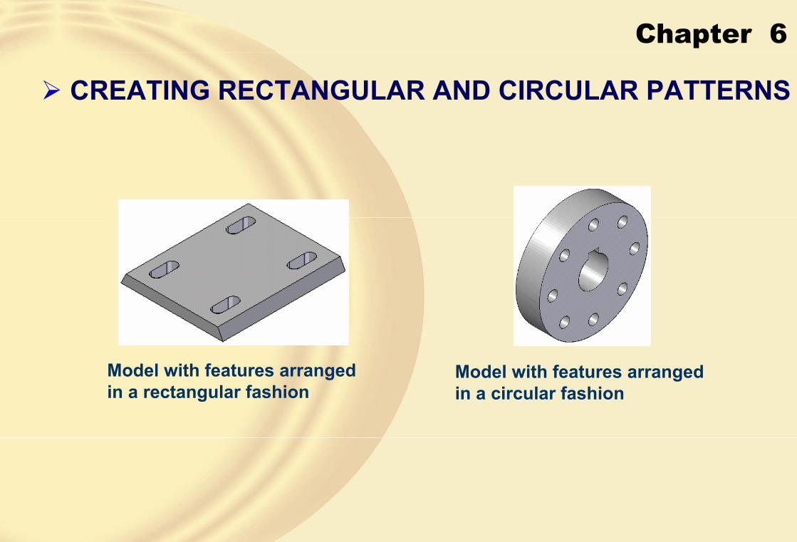
� CREATING RECTANGULAR AND CIRCULAR PATTERNS
Model with features arranged in a rectangular fashion
Model with features arranged in a circular fashion

Chapter 6
• Creating Rectangular Patterns• Select Step
When you invoke the Pattern tool, this step is active and you will be prompted to click on a feature.
• Plane or Sketch StepThis step is used to select the plane on which the profile of a rectangular or circular pattern will be drawn.
• Draw Profile StepThis step is used to draw the profile of a pattern you want to create.

Chapter 6
• Pattern Type Drop-down List
• Fit
• Fill
• Fixed
This drop-down list is used to specify the method of defining the placement of occurrences in the rectangular pattern.
• X/Y
These edit boxes are used to specify the occurrences along the X and Y directions and are available only for the Fit and Fixed pattern types.• X space/Y space
• Width/Height
Chapter 6
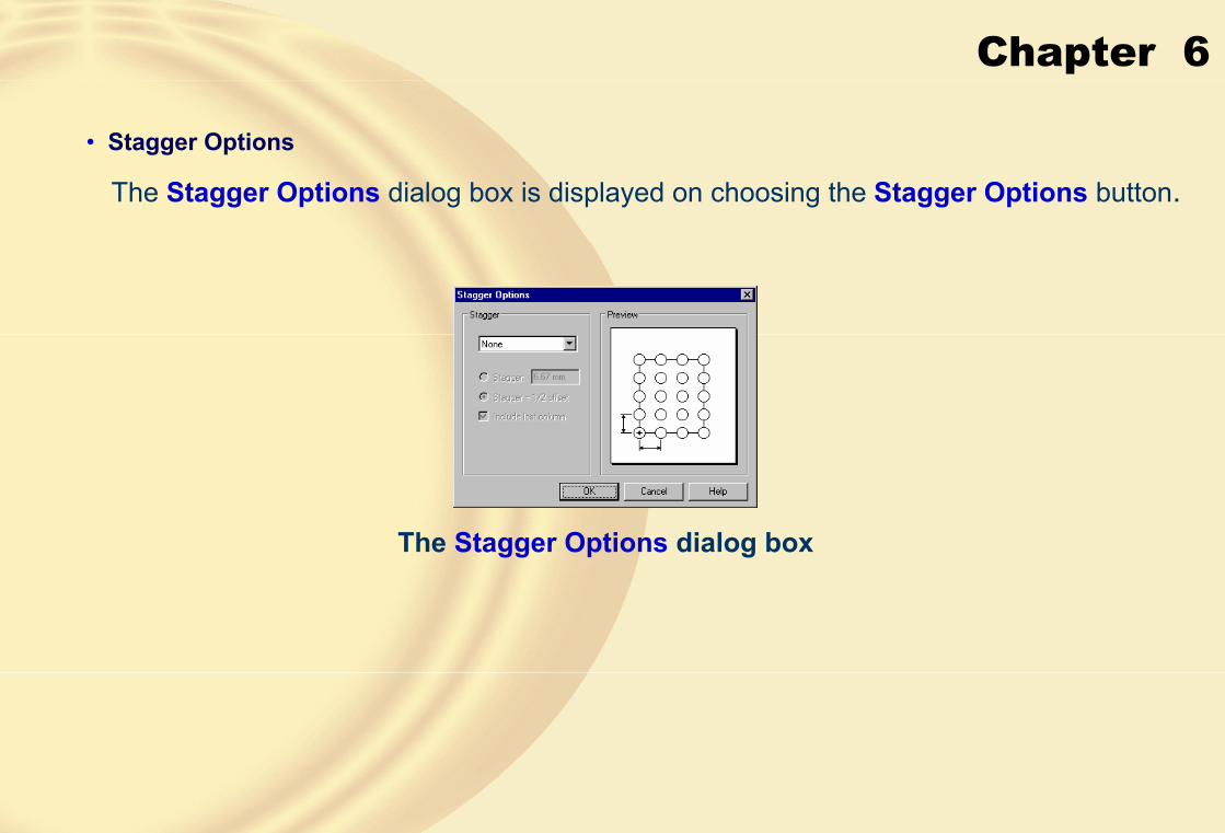
• Stagger Options
The Stagger Options dialog box is displayed on choosing the Stagger Options button.
The Stagger Options dialog box

Chapter 6
• Reference Point
Pattern staggered along the row
Pattern staggered along the column
Selecting the lower left corner of the rectangle as the reference point
Resulting rectangular pattern

Chapter 6
• Suppress Occurrence
Selecting the lower right corner of the rectangle as the reference point
Resulting rectangular pattern
Pattern without suppressing the occurrences
Pattern with some occurrences suppressed

Chapter 6
• Smart/FastThe Smart button is chosen to create patterns that require more complex situations.
Model with a complex pattern situation
• Creating Circular Patterns
• Profile StepTo create a circular pattern, you need to draw its profile, which is a circle or an arc.
This circle or arc acts as the reference to arrange the occurrences in the circular fashion.
• Reference PointThis button is chosen to change the reference point of the pattern.
Chapter 6
• Suppress Occurrence
This button is chosen to suppress some of the occurrences in the circular pattern.
• Pattern Type Drop-down List
This drop-down list is used to specify the method of defining the placement of occurrences in the circular pattern.• Fit
• Fill
• Fixed
• Partial Circle
This button is chosen when you do not want to create a circular pattern through a complete circle.

Chapter 6
Circular pattern placed along partial circle in the counterclockwise direction
Circular pattern placed along partial circle in the clockwise direction
• Full Circle
Full circle circular pattern

Chapter 6
• RadiusThis edit box is used to specify the radius of the profile of the circular pattern.
• Sweep
This edit box is available only when you choose the Partial Circle button and is used to specify the angle of the partial circle.
• Count
This edit box is used to specify the occurrences in the circular pattern.
• Spacing
This edit box is used to specify the individual spacing between the occurrences in the circular pattern.

Chapter 6
� CREATING PATTERN ALONG A CURVE• Select Step
This step is active when you invoke the Pattern Along Curve tool. In this step, you are prompted to click on a feature to pattern.
• Select Curve StepThis step is used to select the curve along which the pattern will be created.
• Pattern CurveThis button enables you to select the curve along which the selected feature will be patterned.
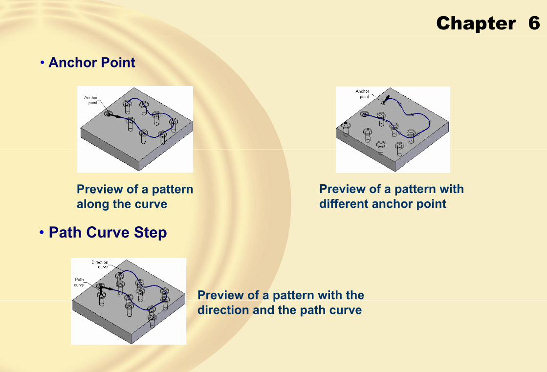
Chapter 6
• Anchor Point
Preview of a pattern along the curve
Preview of a pattern with different anchor point
• Path Curve Step
Preview of a pattern with the direction and the path curve

Chapter 6
• Advanced Definition StepThis step is used to specify the advanced parameters of the pattern along the curve.
• Transformation TypeThis drop-down list is used to specify the types of transformation of occurrences in the resulting pattern.
• Linear
Pattern with linear transformation

Chapter 6
• Full
Pattern with full transformation
• From Plane
This option allows you to select a plane on which the original occurrence and a pattern occurrence are projected and the measured angle defines the orientation of the pattern occurrence.
• Rotation TypeThis drop-down list is used to specify the types of rotation of the occurrences in the resulting pattern.

Chapter 6
• Curve Position
Pattern with curve position rotation
• Feature Position
Pattern with feature position rotation

Chapter 6
• Reference PointThis button is chosen to change the reference point of the pattern.
• Suppress Occurrence
This button is chosen to suppress some of the occurrences of the pattern.
• Insert OccurrenceThis button is chosen to insert additional occurrences in the pattern.
� MIRRORING SELECTED FEATURES AND BODIES• Mirroring Selected Features
The Mirror Copy Feature tool enables you to mirror the selected features about a selected reference plane or planar face.
• Select Features Step
This step enables you to select the features you want to mirror.

Chapter 6
• Plane Step
Model before mirroring the features
Model after mirroring the features about the plane passing through the center of the model
• Mirroring BodiesThe Mirror Copy tool enables you to mirror the selected body about a selected reference plane or planar face.
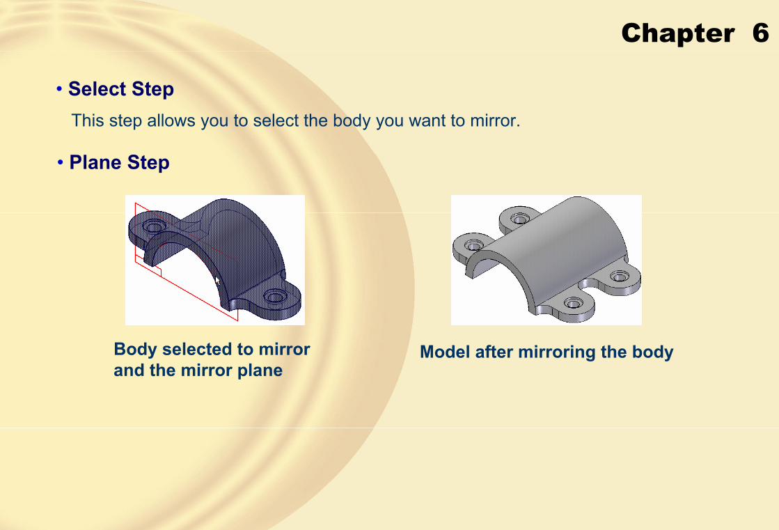
Chapter 6
• Select StepThis step allows you to select the body you want to mirror.
• Plane Step
Body selected to mirror and the mirror plane
Model after mirroring the body

Chapter 6
� Tutorial 1In this tutorial, you will create the model, as shown in Figure A. The dimensions of this model are given in the drawing, as shown in Figure B. After creating the model, save it with the name given below.\Solid Edge\c06\c06tut1.par (Expected time: 30 min)
Figure A Model for Tutorial 1 Figure B Dimensions of the model for Tutorial 1
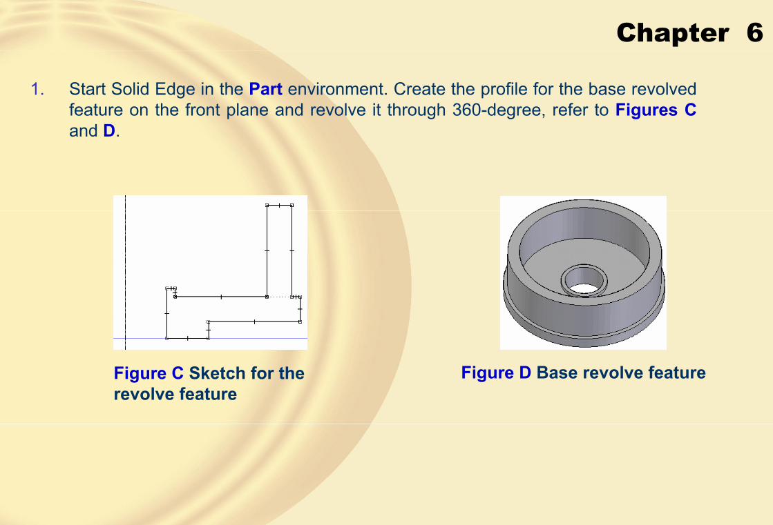
Chapter 6
1. Start Solid Edge in the Part environment. Create the profile for the base revolved feature on the front plane and revolve it through 360-degree, refer to Figures C and D.
Figure C Sketch for the revolve feature
Figure D Base revolve feature
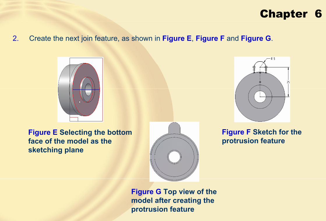
Chapter 6
2. Create the next join feature, as shown in Figure E, Figure F and Figure G.
Figure E Selecting the bottom face of the model as the sketching plane
Figure F Sketch for the protrusion feature
Figure G Top view of the model after creating the protrusion feature

Chapter 6
3. Create a counterbore hole on the new feature, as shown in Figure H.
Figure H Model after creating the counterbore hole
4. Create a circular pattern of the second feature and a hole, as shown in Figure I.
Figure I Final model for Tutorial 1
5. Save the file in \My Documents\Solid Edge\c06\c06tut1.par and then close it.

Chapter 6
� Tutorial 2In this tutorial, you will create the model, as shown in Figure A. Its dimensions are given in the drawing, as shown in Figure B. After creating the model, save it with the name given below.
\Solid Edge\c06\c06tut2.par (Expected time: 30 min)
Figure A Model for Tutorial 2 Figure B Dimensions of the model for Tutorial 2

Chapter 6
1. Create the base feature on the front plane, as shown in Figure C and Figure D. The sketch for the base feature consists of a square with fillet on all the four corners.
Figure C Sketch of the base feature Figure D Model after creating the base feature

Chapter 6
2. On the front face of the base feature, create the circular protrusion feature, as shown in Figure E.
Figure E Model after creating the circular protrusion feature
Figure F Model after creating the top rectangular join features
3. Add two rectangular join features to the cylindrical feature, as shown in Figure F and Figure G, and then create the rectangular cut feature on one of the rectangular join features.
Figure G Model after creating the side rectangular join features

Chapter 6
4. Create all simple holes on the rectangular features by defining the sketch plane on the required planes, as shown in Figure H and Figure I.
Figure H Dimensional hole profiles Figure I Model after creating simple holes
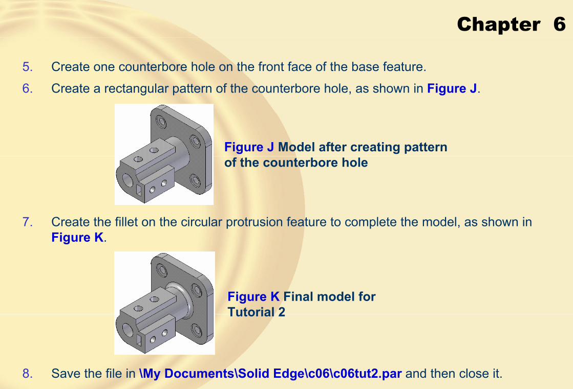
Chapter 6
5. Create one counterbore hole on the front face of the base feature.
6. Create a rectangular pattern of the counterbore hole, as shown in Figure J.
Figure J Model after creating pattern of the counterbore hole
7. Create the fillet on the circular protrusion feature to complete the model, as shown in Figure K.
Figure K Final model for Tutorial 2
8. Save the file in \My Documents\Solid Edge\c06\c06tut2.par and then close it.

Chapter 6
� Tutorial 3In this tutorial, you will create the model of the Guide bracket, as shown in Figure A. Its dimensions are given in the drawing, as shown in Figure B. After creating the model, save it with the name given below.\Solid Edge\c06\c06tut3.par (Expected time: 30 min)
Figure A Model for Tutorial 3 Figure B Dimensions of the model for Tutorial 3
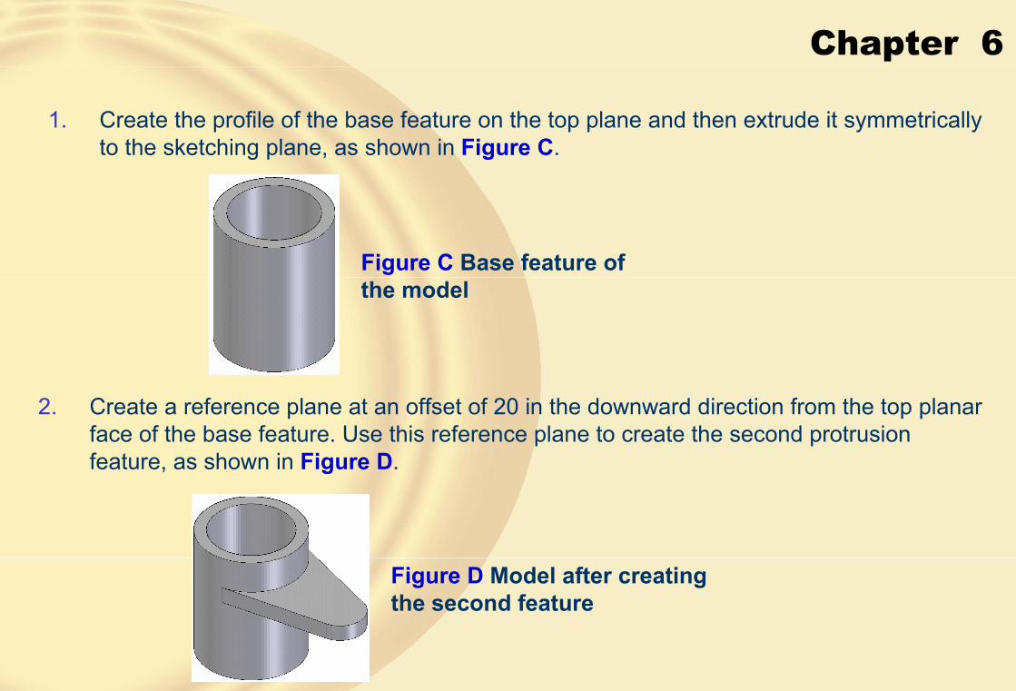
Chapter 6
1. Create the profile of the base feature on the top plane and then extrude it symmetrically to the sketching plane, as shown in Figure C.
Figure C Base feature of the model
2. Create a reference plane at an offset of 20 in the downward direction from the top planar face of the base feature. Use this reference plane to create the second protrusion feature, as shown in Figure D.
Figure D Model after creating the second feature

Chapter 6
3. Mirror the second feature about the top plane, as shown in Figure E.
4. Create the fourth feature on the front plane and extrude it symmetrically through a distance of 22, as shown in Figure F and Figure G.
Figure E Model after mirroring the second feature
Figure F Open profile for the fourth feature
Figure G Model after creating the fourth feature

Chapter 6
5. Create the through simple holes on the second feature and the fourth feature to complete the model, as shown in Figure H.
Figure H Final model of the Guide bracket for Tutorial 3
6. Save the file in \My Documents\Solid Edge\c06\c06tut3.par and then close it.
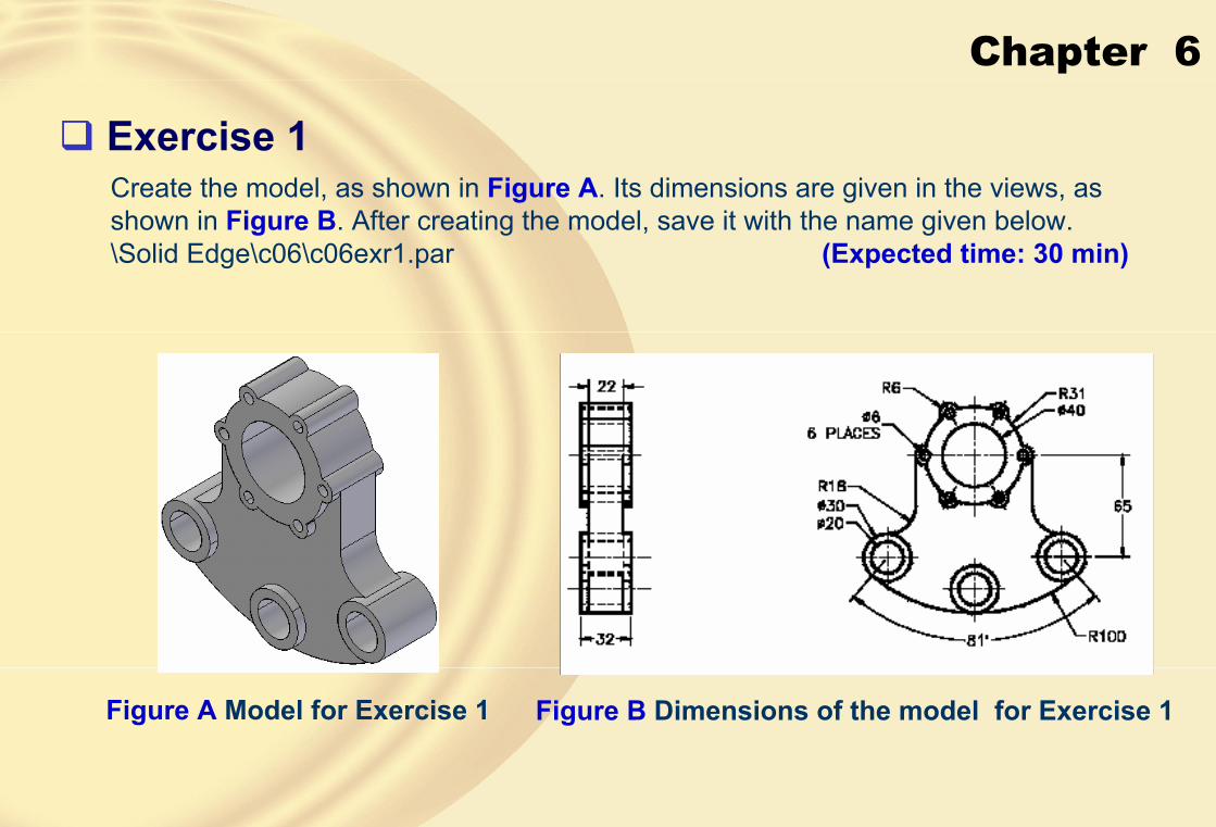
Chapter 6
� Exercise 1Create the model, as shown in Figure A. Its dimensions are given in the views, as shown in Figure B. After creating the model, save it with the name given below.\Solid Edge\c06\c06exr1.par (Expected time: 30 min)
Figure A Model for Exercise 1 Figure B Dimensions of the model for Exercise 1

Chapter 6
� Exercise 2Create the model, as shown in Figure A. Its dimensions are given in the views, as shown in Figure B. After creating the model, save it with the name given below.\Solid Edge\c06\c06exr2.par (Expected time: 30 min)
Figure A Model for Exercise 2 Figure B Dimensions of the model for Exercise 2
Chapter 8
Learning Objectives:• Edit features in a model.
• Edit sketches of the sketched features.
• Redefine the sketching plane of a feature.
• Suppress features.
• Unsuppress features.
• Delete features.
• Copy and paste features.
• Assign different color to a face or a feature.

Chapter 8
� EDITING FEATURES IN A MODEL• Editing is one of the most important aspects of a design process.
• Most of the designs require editing, either when they are being created or after their completion.
• Solid Edge is a feature-based solid modeling tool.
Plate with four counterbore holes Plate with six countersink holes

Chapter 8
• Edit DefinitionWhen you select a feature and invoke this editing tool, the ribbon bar of the tool that was used to create that feature will be displayed with all the steps available in it.
• Edit ProfileThis editing tool is used to directly invoke the sketching environment to edit the profile of a profile-based feature.
• Dynamic Edit
Dynamically editing the model by dragging the sketch
Same model after dynamically editing the profile
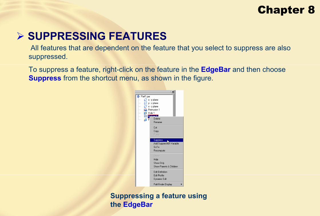
Chapter 8
� SUPPRESSING FEATURESAll features that are dependent on the feature that you select to suppress are also
suppressed.
To suppress a feature, right-click on the feature in the EdgeBar and then choose Suppress from the shortcut menu, as shown in the figure.
Suppressing a feature using the EdgeBar

Chapter 8
� UNSUPPRESSING THE SUPPRESSED FEATURESTo unsuppress a feature, right-click on the suppressed feature in the EdgeBar and then choose Unsuppress from the shortcut menu.
The selected feature will be displayed in the model again.
� DELETING FEATURESSelect the feature to be deleted from the EdgeBar or from the model in the drawing window and press the DELETE key from the keyboard.
The selected feature will be deleted.
� COPYING AND PASTING FEATURESIn Solid Edge, you can copy and paste a feature from the current file to any other file or to some other place in the same file.

Chapter 8
Preview of the hole feature being copied
Three instances of hole placed on the selected plane
Copying a feature from one file to the other by dragging

Chapter 8
� ROLLING BACK THE MODEL TO A FEATURETo roll back the model to a particular feature, select it in theEdgeBar.
Right-click to display the shortcut menu and choose GoTo, as shown in the figure.
Partial view of the shortcut menu to roll back the model to a particular feature
� ASSIGNING COLOR TO A PART, FEATURE, OR FACEIn Solid Edge, you can represent a face or feature of a model differently by assigning a different color to the selected face or feature.
The remaining features will have the color of the model, but theselected face or feature can be assigned a different color.
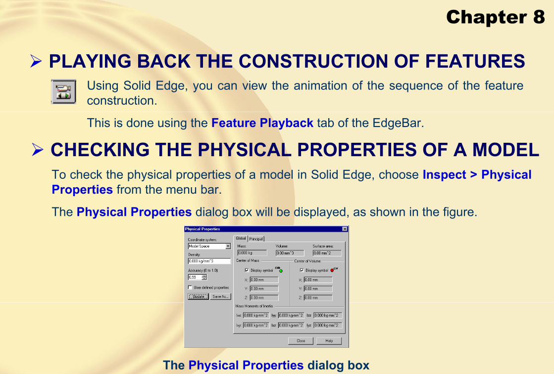
Chapter 8
� PLAYING BACK THE CONSTRUCTION OF FEATURESUsing Solid Edge, you can view the animation of the sequence of the feature construction.
This is done using the Feature Playback tab of the EdgeBar.
� CHECKING THE PHYSICAL PROPERTIES OF A MODELTo check the physical properties of a model in Solid Edge, choose Inspect > Physical Properties from the menu bar.
The Physical Properties dialog box will be displayed, as shown in the figure.
The Physical Properties dialog box

Chapter 8
� MODIFYING THE DISPLAY OF CONSTRUCTION ENTITIES
Solid Edge allows you to show or hide all the construction entities together using the Construction Display dialog box shown in the figure.
To invoke this dialog box, choose the Constriction Display button from the Features toolbar.
The Construction Display dialog box

Chapter 8
� Tutorial 1In this tutorial, you will create the model, as shown in Figure A. Its dimensions are given in the drawing views, as shown in Figure B. After creating the model, modify the central hole in the cylindrical feature to a counterbore hole. The counterbore diameter should be 36 and the hole diameter should be 24. The counterbore depth should be 10.
Also, change the holes on the top planar face of the model to countersink holes with the countersink diameter 14 and hole diameter 8. The countersink angle should be 82-degree. Increase the number of occurrences along the shorter side to 3. Save the model with the name given below.\Solid Edge\c06\c06tut1.par (Expected time: 30 min)
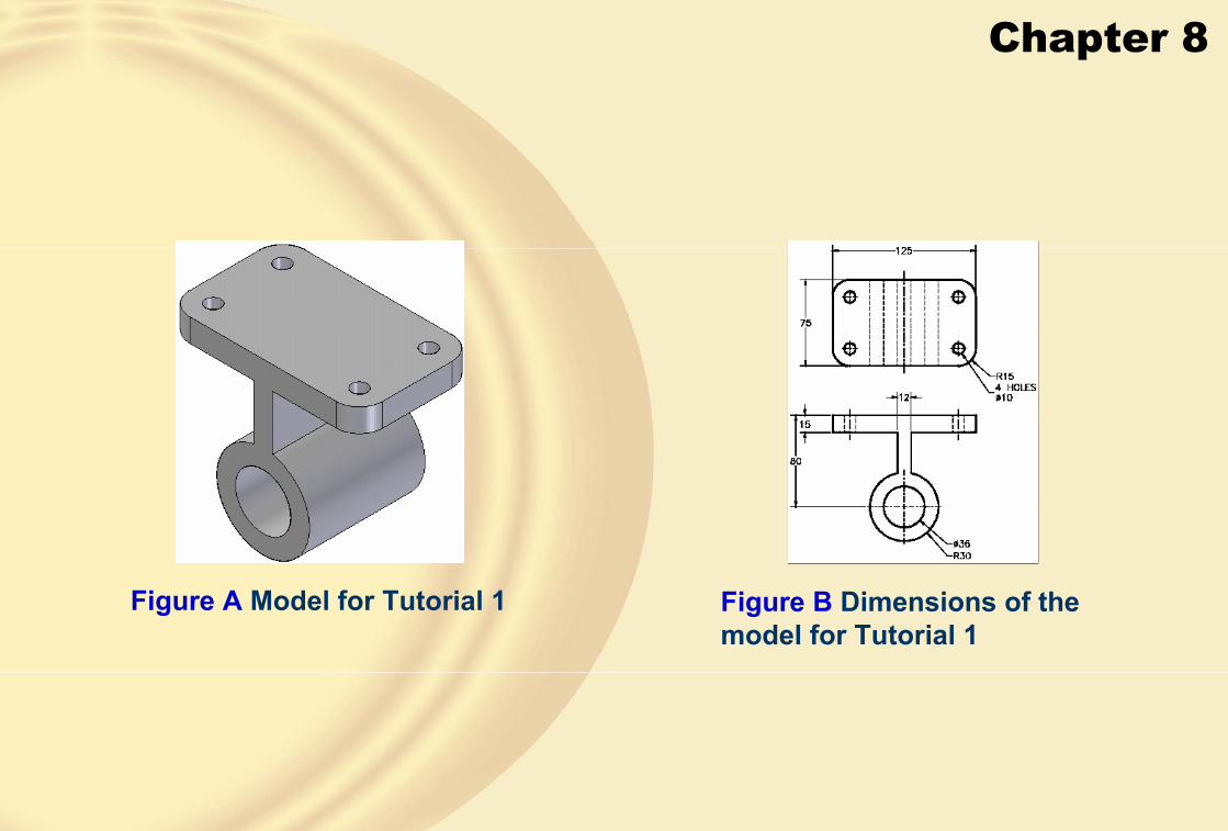
Chapter 8
Figure A Model for Tutorial 1 Figure B Dimensions of the model for Tutorial 1

Chapter 8
1. Start Solid Edge in the Part environment and create the base feature on the front plane,refer to Figure C.
Figure D Model after creating the central hole
Figure C Base feature of the model
2. Create a simple hole in the cylindrical feature of the model, as shown in Figure D.
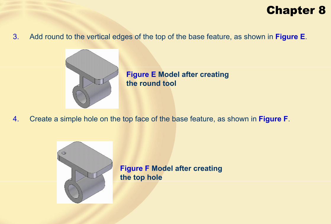
Chapter 8
3. Add round to the vertical edges of the top of the base feature, as shown in Figure E.
4. Create a simple hole on the top face of the base feature, as shown in Figure F.
Figure E Model after creating the round tool
Figure F Model after creating the top hole

Chapter 8
5. Create a rectangular pattern of holes on the top face of the base feature, as shown in Figure G.
Figure G Model after patterning the holes

Chapter 8
6. Modify the central hole and the hole on the top face of the base feature, as shown in Figure H.
7. Modify the number of items in the rectangular pattern of holes, as shown in Figure I.
Figure H Model after editing the holes
Figure I Final model after editing the pattern of holes
8. Save the file in \My Documents\Solid Edge\c07\c07tut1.par and then close it.

Chapter 8
� Tutorial 2In this tutorial, you will create the model, as shown in Figure A. Its dimensions are given in the drawing views, as shown in Figure B. In this model, you will create one of the holes using the Hole tool and the remaining holes will be created by copying and pasting the first hole. Save the model with the name given below.\Solid Edge\c07\c07tut2.par (Expected time: 30 min)
Figure A Model for Tutorial 2 Figure B Dimensions of the model for Tutorial 2
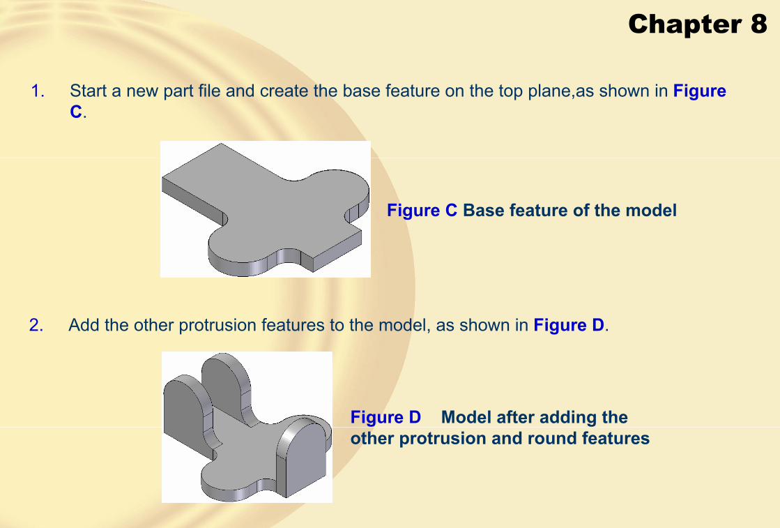
Chapter 8
1. Start a new part file and create the base feature on the top plane,as shown in FigureC.
Figure C Base feature of the model
2. Add the other protrusion features to the model, as shown in Figure D.
Figure D Model after adding the other protrusion and round features
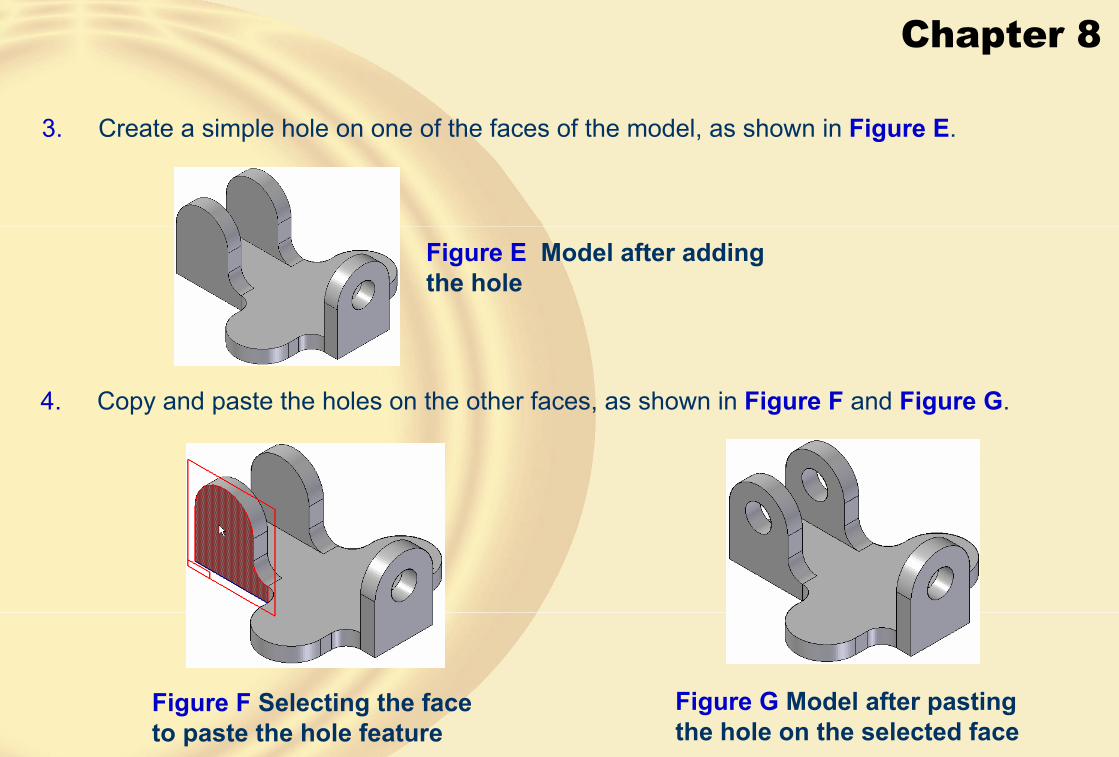
Chapter 8
3. Create a simple hole on one of the faces of the model, as shown in Figure E.
Figure E Model after adding the hole
4. Copy and paste the holes on the other faces, as shown in Figure F and Figure G.
Figure F Selecting the face to paste the hole feature
Figure G Model after pasting the hole on the selected face

Chapter 8
Figure H Final model for Tutorial 2
5. Edit the profiles of the copied holes and make them concentric to the arcs on the faces, as shown in Figure H.
6. Save the file in \My Documents\Solid Edge\c07\c07tut2.par and then close it.

Chapter 8
� Tutorial 3In this tutorial, you will create the model, as shown in Figure A. Its dimensions are given in Figure B. After completing the model, you will modify the dimension 100 of the base to 120 and correspondingly modify the dimensions of the other features. Save the model with the name\Solid Edge\c07\c07tut3.par. (Expected time: 30 min)
Figure A Model for Tutorial 3 Figure B Dimensions of the model for Tutorial 3

Chapter 8
1. Start a new part file and create the base feature on the front plane,as shown in FigureC.
Figure C Base feature of the model
2. Add the other protrusion features on the top face of the model, as shown in Figure D.
Figure D Model after adding features on the top face of the base feature

Chapter 8
3. Add the features on the back face of the model, as shown in Figure E.
Figure E Model after adding features on the back face
4. Create two hole features, as shown in Figure F.
Figure F Model after adding holes

Chapter 8
5. Edit the extrusion depth of the base feature, as shown in Figure G.
6. Change the color of the model to copper.
Figure G Final model after editing the base feature
7. Save the file in \My Documents\Solid Edge\c07\c07tut3.par and then close it.

Chapter 8
� Exercise 1Open the model created in Exercise 1 of Chapter 6 and modify some of its dimensions. After modifying the dimensions, save it with the name given below so that the original file is not modified.\Solid Edge\c07\c07exr1.par (Expected time: 15 min)
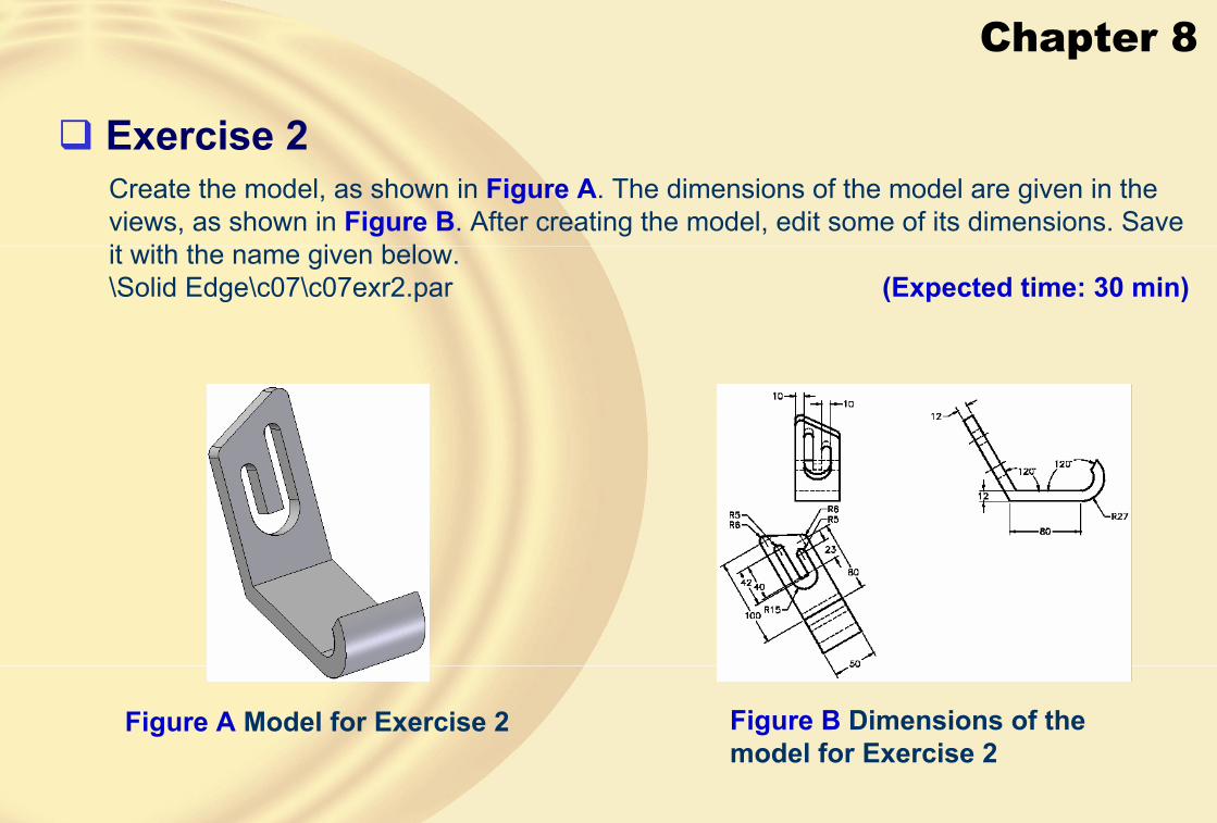
Chapter 8
� Exercise 2Create the model, as shown in Figure A. The dimensions of the model are given in the views, as shown in Figure B. After creating the model, edit some of its dimensions. Save it with the name given below.\Solid Edge\c07\c07exr2.par (Expected time: 30 min)
Figure A Model for Exercise 2 Figure B Dimensions of the model for Exercise 2
Chapter 8
Learning Objectives:• Use the Thread tool for creating external and internal threads.
• Add drafts to models.
• Add lip features.
• Create thin wall features.
• Create thin region features.
• Create ribs.
• Create web networks.
• Create vent features
• Create mounting bosses.

Chapter 8
� ADVANCED MODELING TOOLS• CREATING INTERNAL OR EXTERNAL THREADS
In Solid Edge, you can create internal or external threads using the Thread tool.
The Thread Options dialog box
• StraightThis radio button is selected to create threads on a straight feature.
• TaperThis radio button is selected to create threads on a tapered feature.
• Taper angleYou can enter the taper angle in this edit box or select the predefined taper angles from the drop-down list.

Chapter 8
• Select Cylinder Step
This step is automatically invoked when you exit the Thread Options dialog box.
• Cylinder End StepThis step will be automatically invoked after you select a cylinder or a hole to create threads.
After specifying the parameters in the Thread Options dialog box, this tool works in the three steps that are:
• Parameters StepThis step enables you to specify the parameters of the thread that you want to create.
The options available in this drop-down list are:
• OffsetThis edit box is used to specify the distance between the start of the thread and the cylinder end selected in the second step.

Chapter 8
• Depth
This drop-down list is used to specify the depth up to which the thread will be created.
The options available in this drop-down list are discussed next.
This is the default option and it creates threads through the entire length of the cylinder or hole.
This option enables you to create threads up to a specified depth.
• Type
This drop-down list is used to specify the type of thread you want to create.
• Thread unitThis drop-down list is used to specify the unit of threads.
• Finite value
• To cylinder extent
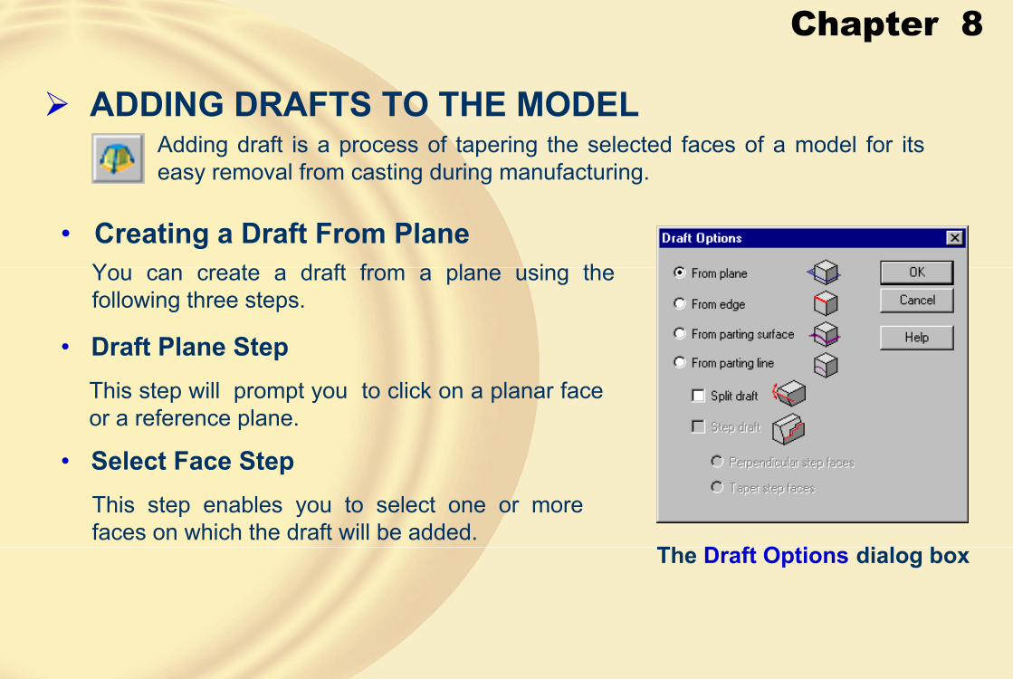
Chapter 8
� ADDING DRAFTS TO THE MODELAdding draft is a process of tapering the selected faces of a model for its easy removal from casting during manufacturing.
The Draft Options dialog box
• Creating a Draft From PlaneYou can create a draft from a plane using the following three steps.
• Draft Plane StepThis step will prompt you to click on a planar face or a reference plane.
• Select Face StepThis step enables you to select one or more faces on which the draft will be added.

Chapter 8
Draft added with top face as the draft plane
Draft added with bottom face as the draft plane
• Draft Direction Step
Defining the draft direction using an inclined line on the upper horizontal edge
Resulting draft
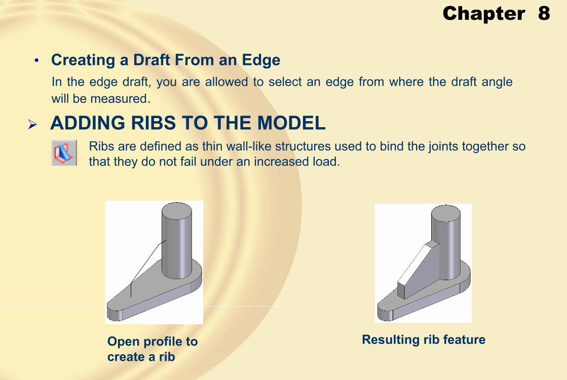
Chapter 8
• Creating a Draft From an EdgeIn the edge draft, you are allowed to select an edge from where the draft angle will be measured.
� ADDING RIBS TO THE MODEL
Open profile to create a rib
Resulting rib feature
Ribs are defined as thin wall-like structures used to bind the joints together so that they do not fail under an increased load.

Chapter 8
• Plane or Sketch StepThis step enables you to select a sketching plane for drawing the profile of the rib feature.
• Draw Profile StepThis step will be automatically invoked when you select the sketching plane for drawing the profile of the rib feature.
• Direction StepThis step enables you to define the direction of rib creation, and therefore, you are prompted to click to accept the displayed side or select the other side in the view.
Preview of the direction in which the rib will not be created
Preview of the direction in which the rib will be created

Chapter 8
• Side StepIn the Side step, you are allowed to specify the side of the sketching plane on which the rib will be created.
• Extend ProfileWith Extend Profile button chosen open profiles can be used for rib feature creation.
Preview of the symmetric rib
Rib feature extended to the adjacent features
Open profile not extended to the adjacent features
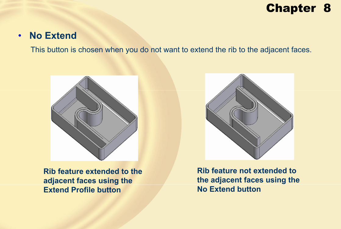
Chapter 8
• No ExtendThis button is chosen when you do not want to extend the rib to the adjacent faces.
Rib feature extended to the adjacent faces using the Extend Profile button
Rib feature not extended to the adjacent faces using the No Extend button
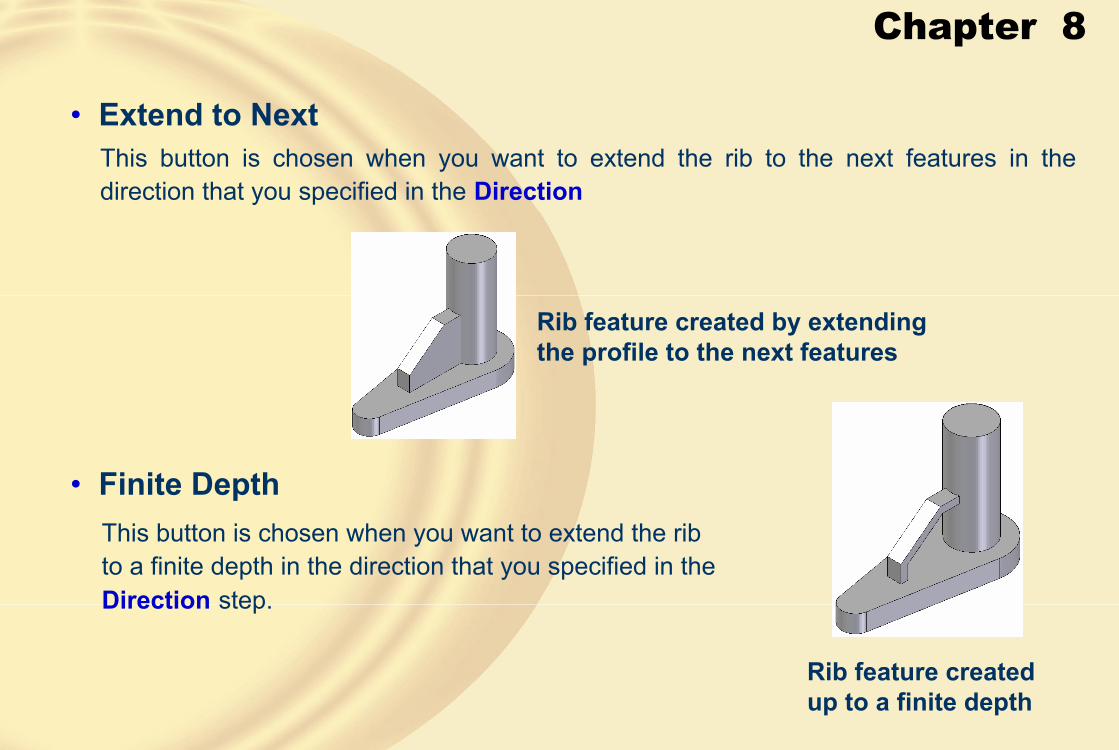
Chapter 8
This button is chosen when you want to extend the rib to the next features in the direction that you specified in the Direction
• Extend to Next
• Finite DepthThis button is chosen when you want to extend the rib to a finite depth in the direction that you specified in theDirection step.
Rib feature created by extending the profile to the next features
Rib feature created up to a finite depth
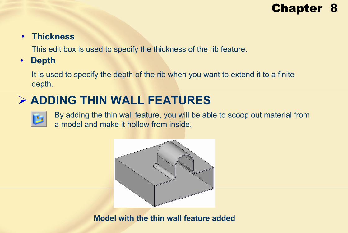
Chapter 8
This edit box is used to specify the thickness of the rib feature.• Thickness
It is used to specify the depth of the rib when you want to extend it to a finite depth.
• Depth
� ADDING THIN WALL FEATURESBy adding the thin wall feature, you will be able to scoop out material from a model and make it hollow from inside.
Model with the thin wall feature added

Chapter 8
• Common Thickness StepThis step enables you to specify the common thickness for the thin wall feature.
• Offset OutsideThe Offset Outside button is chosen to define the wall thickness outside the model with respect to its outer faces.
• Offset Inside
The Offset Inside button is chosen by default and is used to define the wall thickness inside the model with respect to its outer faces.
The Symmetrical button is chosen to calculate the wall thickness equally in both the directions of the outer faces of the model.
• Symmetrical
• Common thicknessThis edit box is used to specify the common thickness for the thin wall feature.

Chapter 8
• Open Faces StepYou can specify the face that you want to remove from the thin wall feature.
Thin wall model with front and left faces removed
• Unique Thickness StepYou can use this step to select faces from which a different wall thickness will be
applied.
Thin wall model with different wall thicknesses

Chapter 8
� ADDING THIN WALLS TO A PARTICULAR REGIONThis option is used to add the thin wall feature to a particular region instead of complete model.
• Faces To Thin StepIn this step, you can select the faces of the region to add the thin wall feature and specify the common thickness.
• Open Faces StepIn this step, you can select the faces that you want to remove from the thin wall region.
Model with the thin wall feature added to a particular region
Selecting the faces of the model to create thin wall region
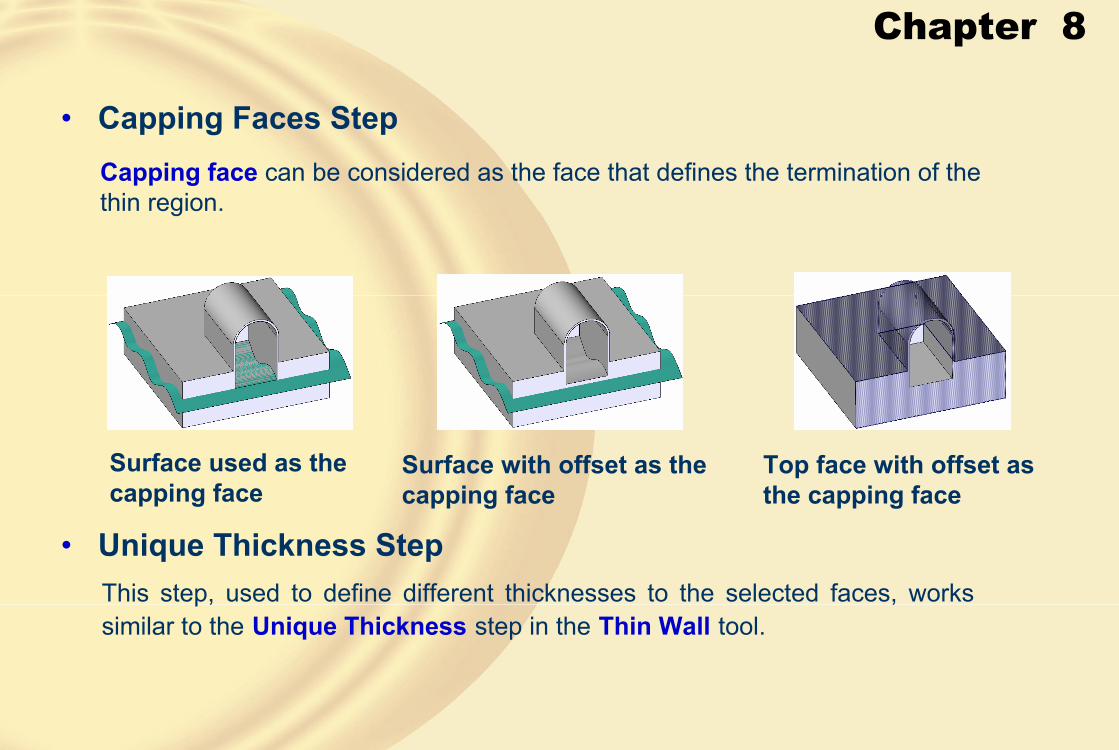
Chapter 8
Capping face can be considered as the face that defines the termination of the thin region.
• Capping Faces Step
Surface used as the capping face
Surface with offset as the capping face
Top face with offset as the capping face
This step, used to define different thicknesses to the selected faces, works similar to the Unique Thickness step in the Thin Wall tool.
• Unique Thickness Step

Chapter 8
� ADDING LIP TO THE MODEL
• Select Edge StepThis step allows you to select the edge along which you want to add a lip or groove.
• Direction StepThis step enables you to specify the direction and size of the lip feature.
The Lip tool enables you to add a lip to the model by adding the material along the selected edges or by adding groove to the model by removing the material along the selected edges.
Location of the rectangle Resulting lip feature

Chapter 8
Location of the rectangle Resulting lip feature
� CREATING WEB NETWORKSThe Web Network tool enables you to create a network of web using open entities.
Resulting web network
Thin wall model and a network of lines
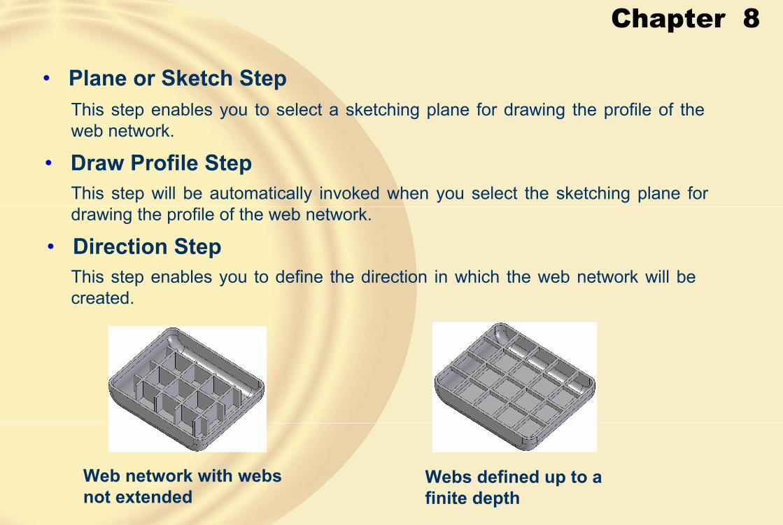
Chapter 8
• Plane or Sketch StepThis step enables you to select a sketching plane for drawing the profile of the web network.
This step will be automatically invoked when you select the sketching plane for drawing the profile of the web network.
• Draw Profile Step
• Direction StepThis step enables you to define the direction in which the web network will be created.
Web network with webs not extended
Webs defined up to a finite depth

Chapter 8
This step is used to add a draft to the webs in the web network. It works similar to the Treatment step in the Protrusion tool.
• Treatment Step
� CREATING VENTSThe Vent tool enables you to create a vent in an existing model by defining the boundary of the vent and the ribs and spars in the vent.
Parameters related to the vent
Resulting model with the vent

Chapter 8
This drop-down list displays the list of settings that you have saved.
• Vent Options Dialog Box OptionsThe options available in this dialog box are discussed next.
• Saved settings
The Vent Options dialog box

Chapter 8
These edit boxes are used to specify the thickness of ribs and spars.
• Thickness Ribs/Spars
Ribs and spars thickness as 2 Ribs and spars thickness as 5
• Extension Ribs/SparsThese edit boxes are used to specify the distance by which the ribs and spars will extend beyond the boundary of the vent.
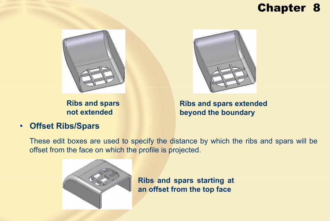
Chapter 8
Ribs and spars not extended
Ribs and spars extended beyond the boundary
These edit boxes are used to specify the distance by which the ribs and spars will be offset from the face on which the profile is projected.
• Offset Ribs/Spars
Ribs and spars starting at an offset from the top face
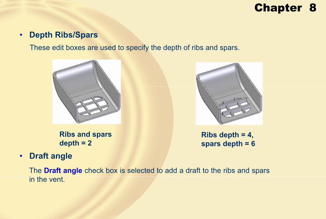
Chapter 8
These edit boxes are used to specify the depth of ribs and spars.
• Depth Ribs/Spars
Ribs and spars depth = 2
Ribs depth = 4, spars depth = 6
The Draft angle check box is selected to add a draft to the ribs and spars in the vent.
• Draft angle
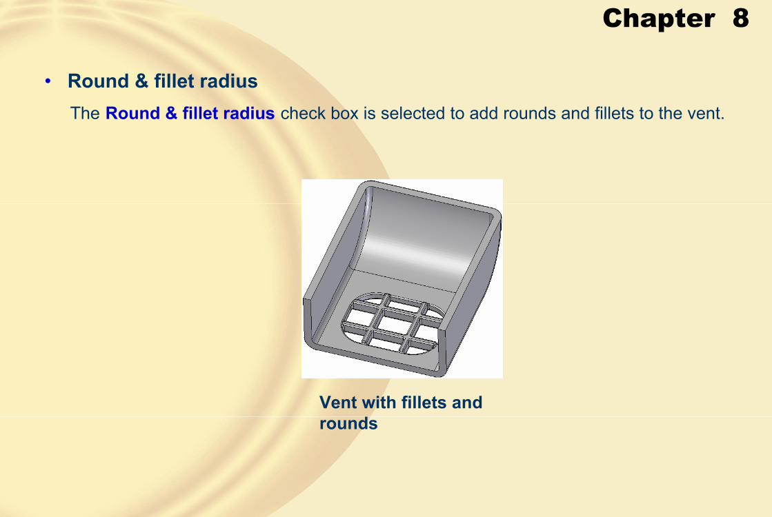
Chapter 8
The Round & fillet radius check box is selected to add rounds and fillets to the vent.
• Round & fillet radius
Vent with fillets and rounds
Chapter 8
• Select Boundary StepIn this step, you can select a chain of entities that will be the boundary of the vent.
• Select Ribs StepIn this step, you can select the entities that you want to use as ribs in the vent.
• Select Spars StepIn this step, you can select the entities that you want to use as spars in the vent.
• Extent StepThis step is used to specify the side and the extent of the vent.

Chapter 8
� CREATING MOUNTING BOSSThe Mounting Boss tool enables you to create mounting boss features, which are used in the plastic components to accommodate fasteners.
Model with four mounting bosses
The Mounting Boss Options dialog box
Chapter 8
The options available in this dialog box are discussed next.
• Mounting Boss Options Dialog Box Options
This drop-down list displays the list of settings that you have saved.
• Saved settings
The options available in this area are used to set the parameters of the mounting boss feature.
• Settings Area
This edit box is used to specify the diameter of the mounting boss.
• Boss diameter
This check box is selected to create a hole on the top face of the mounting boss.
• Mounting hole
This check box is used to create a mounting box with ribs.• Stiffening ribs
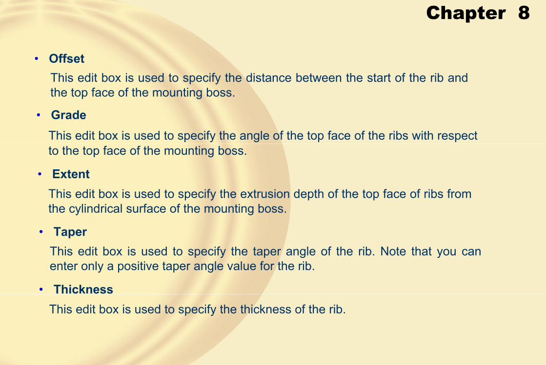
Chapter 8
This edit box is used to specify the taper angle of the rib. Note that you can enter only a positive taper angle value for the rib.
• OffsetThis edit box is used to specify the distance between the start of the rib and the top face of the mounting boss.
• GradeThis edit box is used to specify the angle of the top face of the ribs with respectto the top face of the mounting boss.
• ExtentThis edit box is used to specify the extrusion depth of the top face of ribs from the cylindrical surface of the mounting boss.
• Taper
This edit box is used to specify the thickness of the rib.• Thickness

Chapter 8
This check box is selected to add a draft to the mounting boss.• Add draft
Mounting bosses without draft
Mounting bosses with draft
This check box is selected to add rounds and fillets to the mounting boss.
• All rounds and fillets

Chapter 8
This step enables you to select a plane for placing the profiles of the mounting bosses.
• Plane Step
In this step, you can place the profiles of the mounting boss on the selected plane.
• Mounting Boss Step
Profiles for four mounting bosses
In this step, can specify the side for creating the mounting boss.
• Extent Step
Chapter 8
By Reordering, you change the sequence in which the features were created in the model.
� REORDERING FEATURES
Thin wall created around cavities
Original model required
Reordering features in the Edge Bar
Chapter 8
� TUTORIAL 1In this tutorial, you will create the model of the cover shown in Figure A. Its dimensions are given in Figure B. The outer fillet in Figure B is removed for dimensioning purpose. The radius of this fillet is 8. A draft of 1-degree needs to be added to the base feature of the model. The parameters of mounting bosses are give next.
Boss diameter = 4, hole diameter = 2, hole depth = 5, rib offset = 3, rib grade = 10-degree, rib extent = 1, rib taper = 10-degree, rib thickness = 1.
Save the model with the name given below. (Expected time: 45min)
Figure A Model for Tutorial 1
Figure B Dimensions of the model for Tutorial 1. Fillets removed for clarity
Chapter 8
1. Start Solid Edge in the Part environment. Create the base feature on the front plane, refer to Figure C.
Figure C Base feature of the model
2. Add a draft to the base feature.
3. Add rounds to the sharp edges of the model, refer to Figure D.
Figure D Viewing the model from the bottom after adding the draft and round

Chapter 8
Figure F Model after creating the cutouts
Figure E Model after creating the thin wall feature
5. Create two cutouts in the model, refer to Figure F.
4. Add a thin wall feature to the model, refer to Figure E.
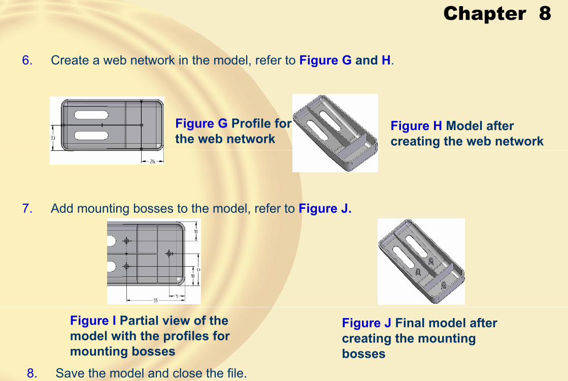
Chapter 8
6. Create a web network in the model, refer to Figure G and H.
Figure G Profile for the web network
Figure H Model after creating the web network
Figure J Final model after creating the mounting bosses
Figure I Partial view of the model with the profiles for mounting bosses
7. Add mounting bosses to the model, refer to Figure J.
8. Save the model and close the file.

Chapter 8
� TUTORIAL 2In this tutorial, you will create the model of the ice tray shown in Figure A. Its dimensions are given in the drawing views shown in Figure B. Save the model with the name given below.
(Expected time: 30 min)
Figure A Model for Tutorial 2 Figure B Dimensions of the model for Tutorial 2
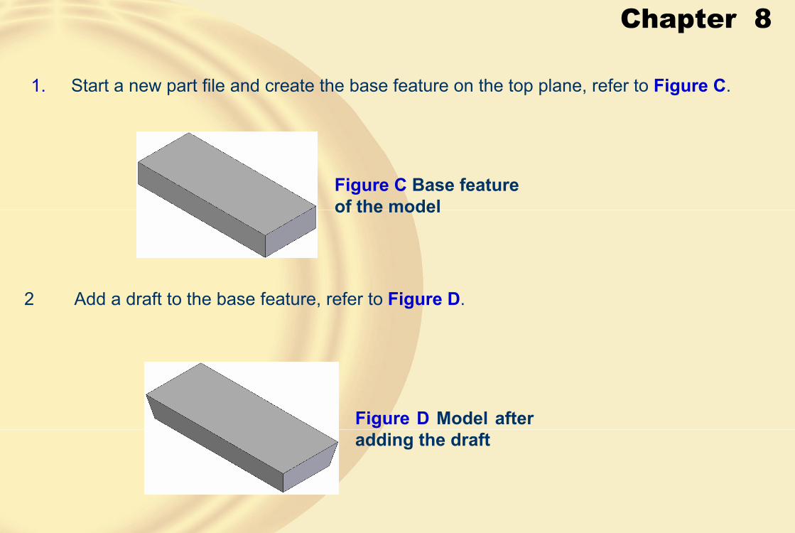
Chapter 8
1. Start a new part file and create the base feature on the top plane, refer to Figure C.
2 Add a draft to the base feature, refer to Figure D.
Figure C Base feature of the model
Figure D Model after adding the draft

Chapter 8
3. Add a thin wall feature to the model, refer to Figure E
4. Create a web network in the model, refer to Figure F and G.
Figure F Model after drawing sketch for the web network
Figure G Model after creating the web network
Figure E Model after adding the thin wall feature
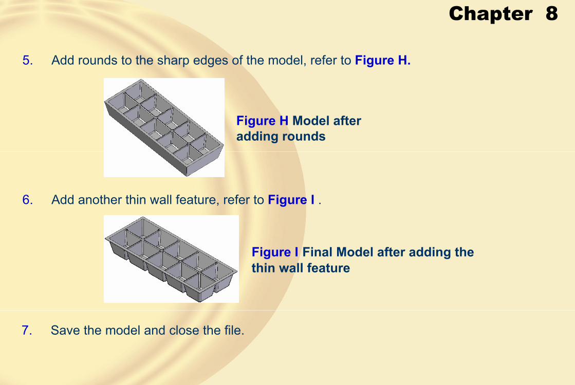
Chapter 8
5. Add rounds to the sharp edges of the model, refer to Figure H.
6. Add another thin wall feature, refer to Figure I .
7. Save the model and close the file.
Figure H Model after adding rounds
Figure I Final Model after adding the thin wall feature

Chapter 8
� TUTORIAL 3In this tutorial, you will create the model shown in Figure A. Its dimensions are given in the drawing views shown in Figure B. Save the model.
(Expected time: 30 min)
Figure B Dimensions of the model for Tutorial 3
Figure A Model for Tutorial 3

Chapter 8
1. Start a new part file and create the base feature on the top plane, refer to Figure C.
2. Add the remaining protrusion features to the base feature, refer to Figure D.Figure C Base feature of the model
Figure D After adding the remaining protrusion features

Chapter 8
3. Add holes to the model, refer to Figures E and F.
Figure E Figure F.
Figure G Profile for the rib feature
Figure H Specifying direction of the rib
4. Create the rib feature, refer to Figures G , through I.

Chapter 8
5 Save the model and close the file.
Figure I Model after creating the rib feature
Chapter 8
� Exercise 1Create the model shown in Figures A. Its dimensions are given in the views shown in Figure B. After creating the model, save it.
(Expected time: 30 min)
Figure A Model for Exercise 1
Figure B Dimensions of the model

Chapter 8
� Exercise 2Create the model shown in Figure A. Its dimensions are given in Figure B.
(Expected time: 30 min)
Figure A Model for Exercise 2 Figure B Dimensions of the model

Chapter 9
• Create swept protrusion.
• Create swept cutout.
• Create lofted protrusion.
• Create lofted cutout.
• Create helical protrusion.
• Create normal protrusion.
• Create normal cutout.
� Learning Objectives
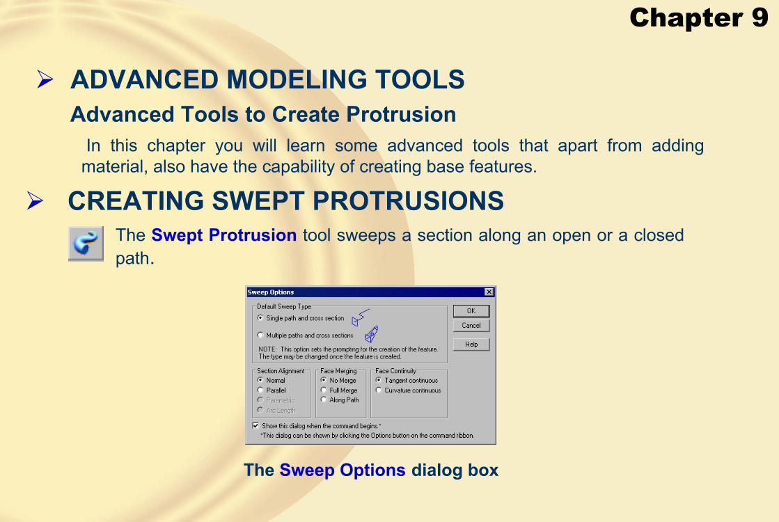
Chapter 9
� ADVANCED MODELING TOOLSAdvanced Tools to Create Protrusion
In this chapter you will learn some advanced tools that apart from adding material, also have the capability of creating base features.
� CREATING SWEPT PROTRUSIONSThe Swept Protrusion tool sweeps a section along an open or a closed path.
The Sweep Options dialog box

Chapter 9
• Single path and cross section OptionThis option is used to sweep a section along an open or a closed path.
Closed path and closed section used to create the swept protrusion
Path and the section used to create the swept protrusion
Reference plane created at the point of selection on the path
• Path Step
This step enables you to define a path along which the section will be swept.

Chapter 9
• Cross Section StepClick to specify the location of the reference plane where the cross-section needs to be drawn.
• Relative OrientationIt enables you to specify that the cross-section will remain oriented relative to the path used for creating a sweep.
• Fixed OrientationThis button is used when you want the cross-section to be always parallel to the sketch plane while sweeping.
Swept protrusion created using the Relative Orientation button
Swept protrusion created using the Fixed Orientation button

Chapter 9
• Multiple paths and cross sections OptionThe Multiple paths and cross sections option present in the Sweep Options dialog box uses multiple cross-sections and multiple paths to create the swept protrusion.
Three paths and a cross-section Swept protrusion
Two cross-sections and a path to create multiple section swept protrusion
Swept protrusion

Chapter 9
� CREATING SWEPT CUTOUTSThe procedure used to create the swept cutout is the same as that was used to create a swept protrusion.
Swept cutout created using the cross-section and the path
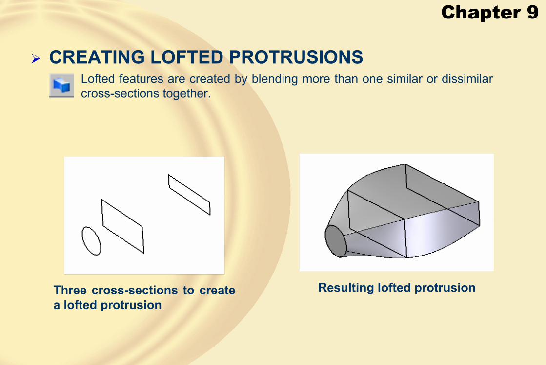
Chapter 9
� CREATING LOFTED PROTRUSIONS
Three cross-sections to create a lofted protrusion
Resulting lofted protrusion
Lofted features are created by blending more than one similar or dissimilar cross-sections together.

Chapter 9
• Cross Section Order OptionThe Cross Section Order button is used to reorder the sequence of sections that blend with each other.
The Cross Section Order dialog box

Chapter 9
• Define Start PointThe Define Start Point button is used to redefine the start points of the sections that take part in blending,
Three sections and their start points joined by a dotted line
Lofted protrusion
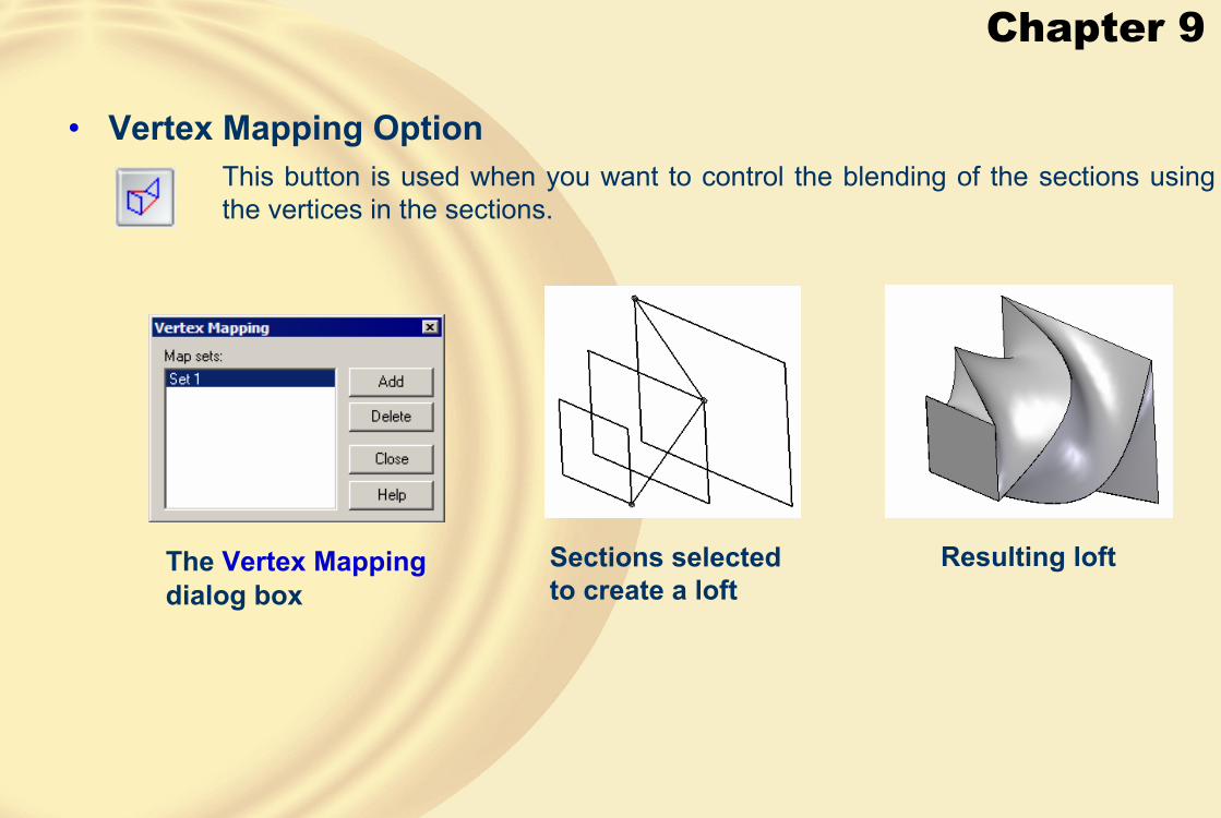
Chapter 9
• Vertex Mapping OptionThis button is used when you want to control the blending of the sections using the vertices in the sections.
The Vertex Mappingdialog box
Sections selected to create a loft
Resulting loft

Chapter 9
Points added on the circle Lofted protrusion created between a circle and a pentagon
Points numbered on two sections
Loft created
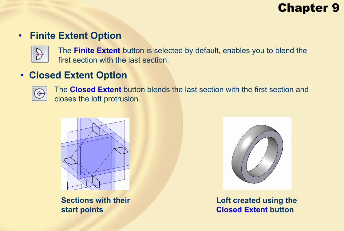
Chapter 9
• Finite Extent Option
• Closed Extent Option
The Finite Extent button is selected by default, enables you to blend the first section with the last section.
The Closed Extent button blends the last section with the first section and closes the loft protrusion.
Sections with their start points
Loft created using the Closed Extent button

Chapter 9
• End 1 and End 2These drop-down lists are available under the Extent Step and provide theNatural and Normal to section options.
Loft feature created with the Natural option
Sections, selection points, and sequence of selection
Difference between the two end conditions
Loft feature created with the Normal to section option
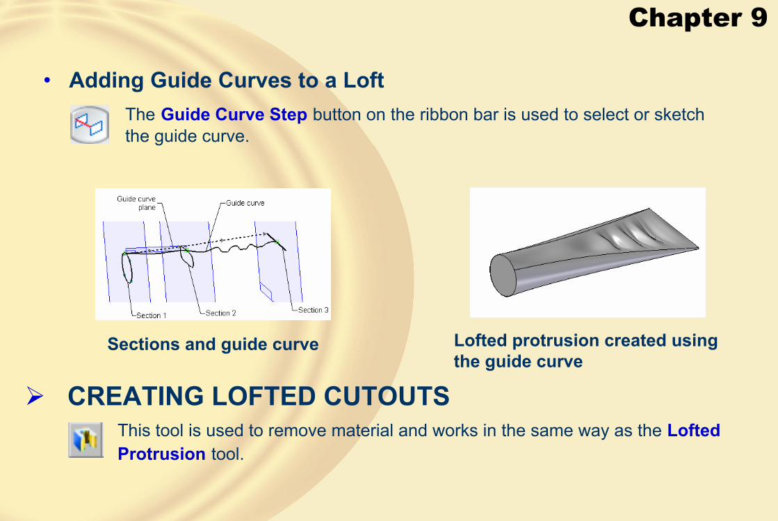
Chapter 9
• Adding Guide Curves to a LoftThe Guide Curve Step button on the ribbon bar is used to select or sketch the guide curve.
Sections and guide curve Lofted protrusion created using the guide curve
� CREATING LOFTED CUTOUTSThis tool is used to remove material and works in the same way as the Lofted Protrusion tool.
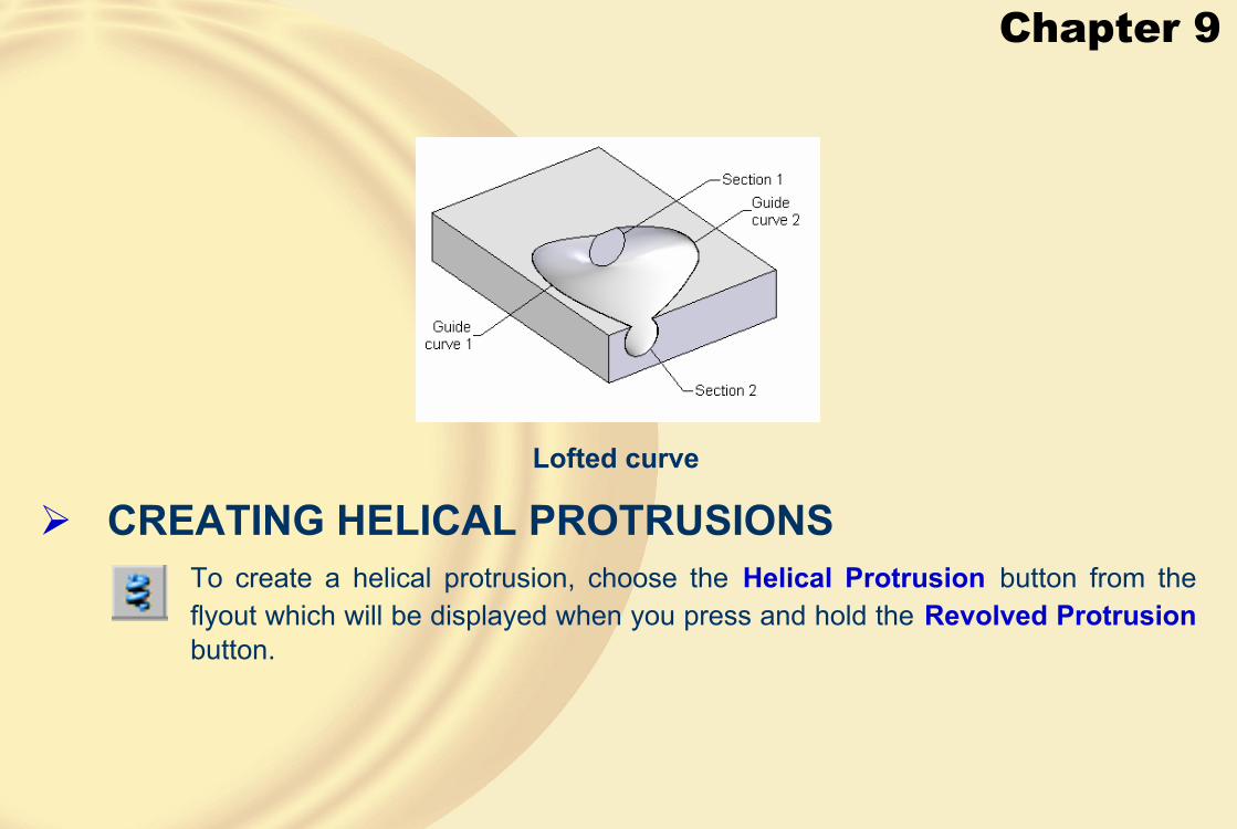
Chapter 9
Lofted curve
� CREATING HELICAL PROTRUSIONSTo create a helical protrusion, choose the Helical Protrusion button from the flyout which will be displayed when you press and hold the Revolved Protrusionbutton.

Chapter 9
• Helix Options
The Parallel option enables you to create a helical protrusion in which the cross-section remains parallel to the axis, while revolving around it.
The Helix Options dialog box
Cross-section and axis
Helical protrusion
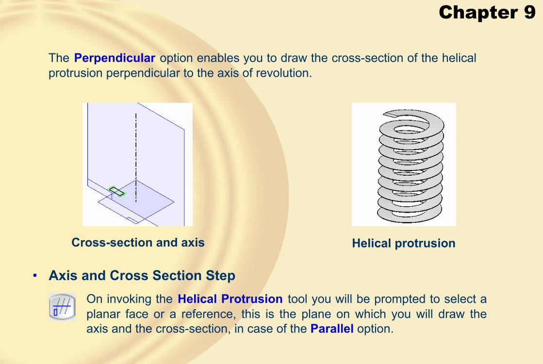
Chapter 9
The Perpendicular option enables you to draw the cross-section of the helical protrusion perpendicular to the axis of revolution.
Cross-section and axis Helical protrusion
• Axis and Cross Section StepOn invoking the Helical Protrusion tool you will be prompted to select a planar face or a reference, this is the plane on which you will draw the axis and the cross-section, in case of the Parallel option.
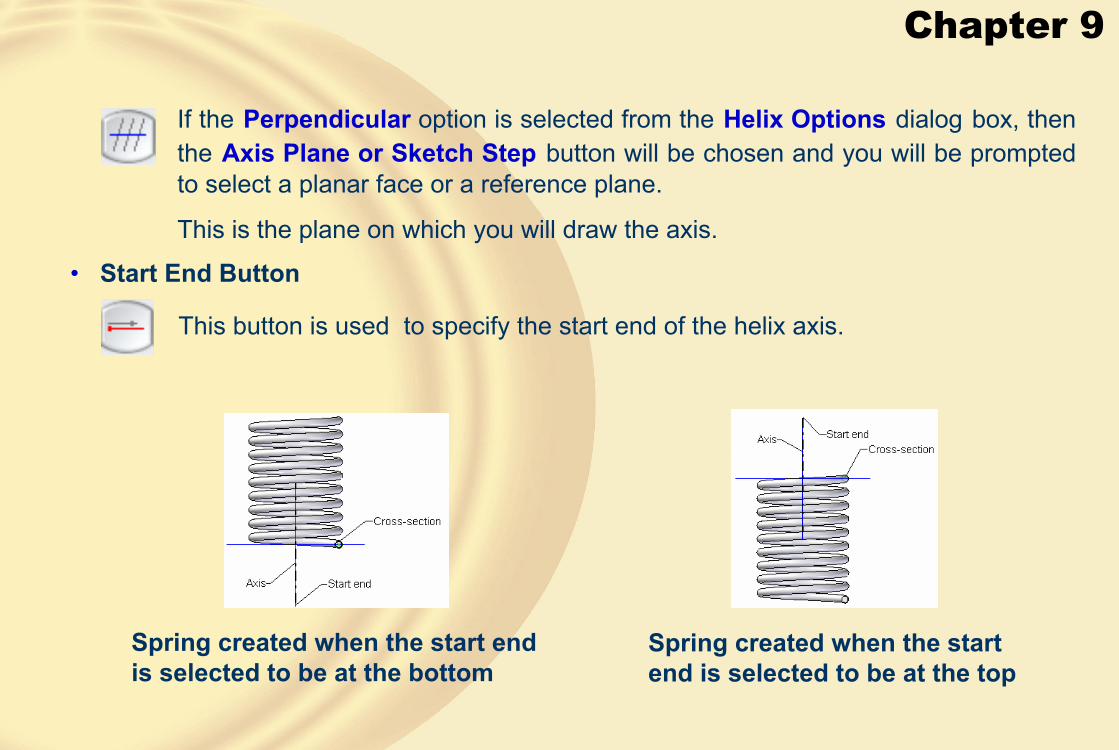
Chapter 9
If the Perpendicular option is selected from the Helix Options dialog box, then the Axis Plane or Sketch Step button will be chosen and you will be prompted to select a planar face or a reference plane.
This is the plane on which you will draw the axis.
• Start End Button
This button is used to specify the start end of the helix axis.
Spring created when the start end is selected to be at the bottom
Spring created when the start end is selected to be at the top

Chapter 9
• Parameters Button
• Axis length & Pitch
Parameter Button is used to enter the helix parameters.
This option allows you to specify the pitch of the helix and it assumes the length of the axis as the height of the helical protrusion.
This option enables you to specify the number of turns in the helix and assumes the length of the axis as the height of the helical protrusion.
• Axis length & Turns
• Pitch & Turns
This option enables you to specify the pitch of the helix and the number of turns.
The Helix Parameters dialog box

Chapter 9
The pitch of the helix can be specified in this edit box.
In this drop-down list, the three above-mentioned methods of creating a helical protrusion are available.
• Helix method
The number of turns of the helical protrusion can be specified in this edit box.• # Turns
• Pitch
• Right-handed
The right-handed helical protrusion creates the spring whose direction matches the direction of the curled fingers of the right hand, when the thumb of the right hand points from the start point to the end point of the axis.
Right-handed spring

Chapter 9
• Left-handed
The left-handed helical protrusion creates the spring whose direction matches the direction of the curled fingers of the left hand, when the thumb of the right hand points from the start point to the end point of the axis.
Left-handed springThe options in this area of the dialog box are used to specify the parameters related to the taper of the helix.
• Taper Area
• Drop-down List
The drop-down list is used to specify the taper methods.
Tapered specified by the start and end radii

Chapter 9
Inward tapered spring Outward tapered spring
The options in this area of the dialog box are used to specify the parameters related to the pitch of the helix.
• Pitch Area
The drop-down list is used to specify the pitch methods.
• Drop-down List
Tapered specified by the start and end pitch values

Chapter 9
� CREATING NORMAL PROTRUSIONSThis tool is used to create a normal protrusion by selecting a closed curve.
Material added outside the curvesMaterial added to the curves
� CREATING NORMAL CUTOUTS
This tool is used to remove material.

Chapter 9
� TUTORIAL 1In this tutorial, you will create the model shown in Figure A. This model is the Upper Housing of a motor blower assembly. Figure B shows the left-side view of the top view, top view, front view, and the sectioned left-side view of the model. All dimensions are in inches.
(Expected time: 45 min)
Figure A Isometric view of the Upper Housing
Figure B Views and dimensions of the Upper housing

Chapter 9
1. Create the base feature on the front plane.This feature is extruded symmetrically on both sides of the front plane, refer to Figures C and D.
Figure C Sketch of the base feature Figure D Base feature
2. On the front plane create a swept protrusion feature, refer to Figures E through O.
Figure E Sketch of the path
Figure F Profile plane at the end of the path
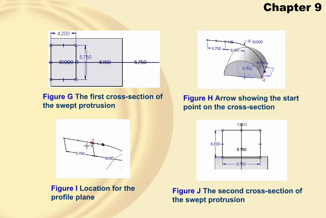
Chapter 9
Figure H Arrow showing the start point on the cross-section
Figure G The first cross-section of the swept protrusion
Figure I Location for the profile plane
Figure J The second cross-section of the swept protrusion

Chapter 9
Figure K Arrow showing the start point on the second cross-section
Figure L Location for the last profile plane
Figure M The third cross-section of the swept protrusion
Figure N Arrow showing the start point on the third cross-section
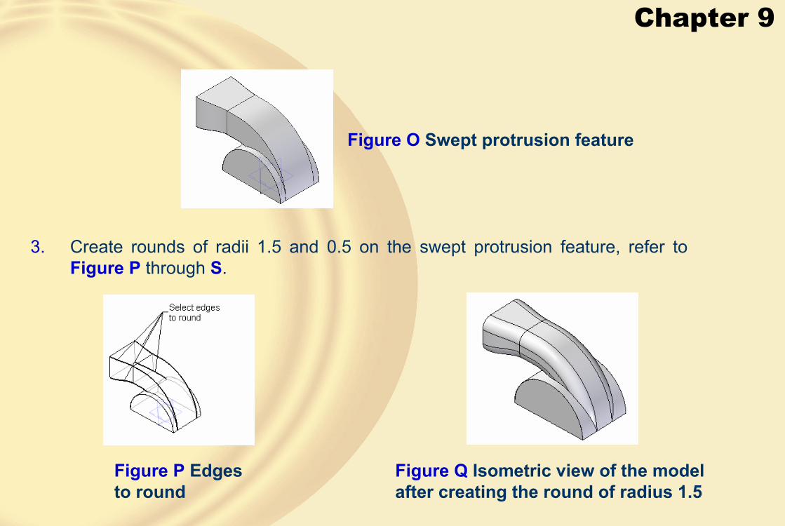
Chapter 9
Figure O Swept protrusion feature
3. Create rounds of radii 1.5 and 0.5 on the swept protrusion feature, refer to Figure P through S.
Figure P Edges to round
Figure Q Isometric view of the model after creating the round of radius 1.5

Chapter 9
Figure R Edge to round Figure S Edge after creating the round
4. Create a thin wall feature on the model, refer to Figure T.
Figure T Thin wall feature created

Chapter 9
5. Create cutout features, refer to Figure U through Figure X.
Figure V Model after creating the cutout feature
Figure W Sketch of the cut feature
Figure X Model after creating the cutout feature
Figure U Sketch of the cutout feature

Chapter 9
6. Create a Protrusion feature on the base feature, refer to Figures Y and Z.
Figure Y Sketch of the protrusion feature Figure Z Model after creating the protrusion feature
7. Mirror the previous protrusion feature to the left side of the model, refer to Figure AA.
Figure AA Model after mirroring the protrusion

Chapter 9
9. Create a pattern of the hole feature, refer to Figure AC.
8. Create a hole feature on the previous feature, refer to Figure AB.
Figure AB Hole on the protrusion feature
Figure AC Complete model
10. Save the model

Chapter 9
In this tutorial, you will create the model shown in Figure A. Figure B shows the section views of the loft feature. Use these sections to create the loft feature. After creating the model, save it.
(Expected time: 45 min)
� TUTORIAL 2
Figure A Isometric view of the model for Tutorial 2
Figure B Front and the section views of the model
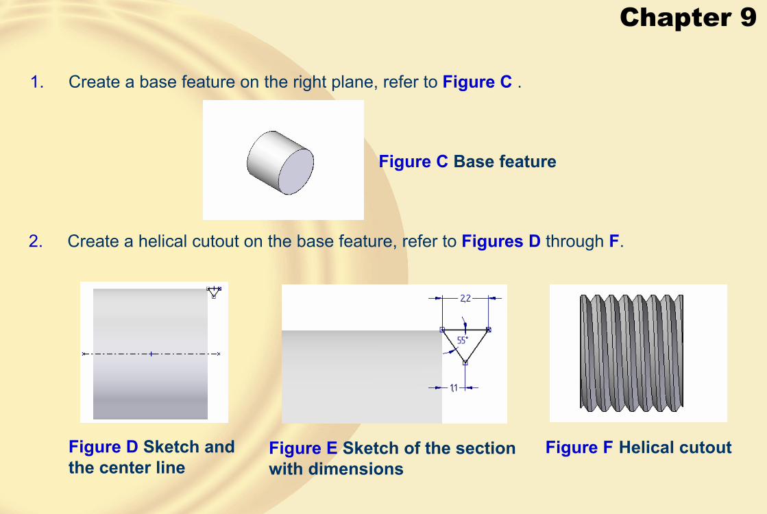
Chapter 9
1. Create a base feature on the right plane, refer to Figure C .
2. Create a helical cutout on the base feature, refer to Figures D through F.
Figure C Base feature
Figure D Sketch and the center line
Figure E Sketch of the section with dimensions
Figure F Helical cutout

Chapter 9
3. Create a protrusion feature on the end face of the base feature, refer to Figure G.
4. Create the cutout to create a slot on the cylindrical feature and then create a pattern of the slot, see Figures H through J.
Figure G Third feature
Figure H Sketch of the section with dimensions
Figure I Cutout Figure J Model after creating the pattern

Chapter 9
5. Create a revolved protrusion, refer to Figures K and L.
Figure K Sketch to revolve Figure L Model after creating the revolved protrusion
6. Create a revolved protrusion feature on the end face of the previous feature, refer to Figures M and N.
Figure M Sketch to revolve
Figure N Model after creating the revolved protrusion
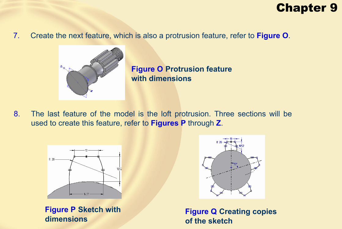
Chapter 9
8. The last feature of the model is the loft protrusion. Three sections will be used to create this feature, refer to Figures P through Z.
7. Create the next feature, which is also a protrusion feature, refer to Figure O.
Figure O Protrusion feature with dimensions
Figure P Sketch with dimensions
Figure Q Creating copies of the sketch

Chapter 9
Figure R Final sketch of first section
Figure S Start point on the section
Figure T Sketch after scaling Figure U Sketch after revolving
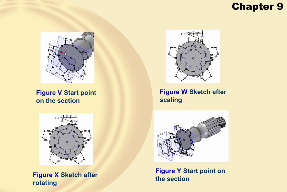
Chapter 9
Figure V Start point on the section
Figure W Sketch after scaling
Figure X Sketch after rotating
Figure Y Start point on the section

Chapter 9
Figure Z Model after creating all features
9. Save the model and then close the file.
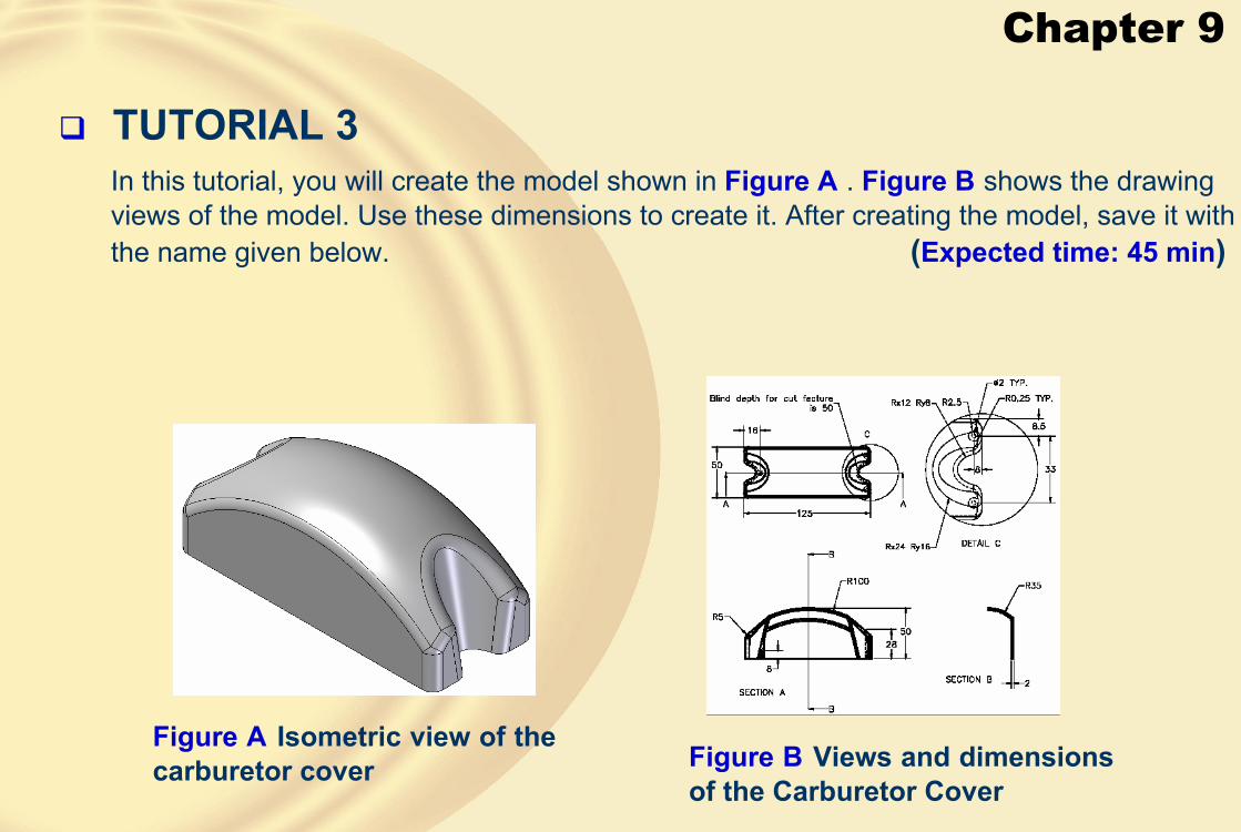
Chapter 9
� TUTORIAL 3In this tutorial, you will create the model shown in Figure A . Figure B shows the drawing views of the model. Use these dimensions to create it. After creating the model, save it with the name given below. (Expected time: 45 min)
Figure B Views and dimensions of the Carburetor Cover
Figure A Isometric view of the carburetor cover

Chapter 9
1. Create the base feature on the top plane, refer to Figure C.
2. Create a swept cutout on the base feature, refer to Figures D through G.
Figure C Rectangular block
Figure D Sketch of the path Figure E Profile plane for cross-section

Chapter 9
3. Create a lofted cutout on the bottom face of the base feature, refer to Figures H throughJ.
Figure F Sketch with constraints and dimensions
Figure G Swept cutout
Figure H Sketch with constraints and dimensions of the first cross-section
Figure I Sketch with constraints and dimensions of the second cross-section

Chapter 9
4. Create a mirror copy of the lofted cutout, refer to Figure K .Figure J Lofted cutout
Figure K Profile plane for the cross-section

Chapter 9
5. Create a round, refer to Figures L and M.
6. Create a thin wall feature, refer to Figure N .
Figure M Model after creating the round
Figure L Edges selected for creating the round
Figure N Thin wall feature

Chapter 9
7. Create the next feature, which is a mounting boss created on the bottom face of the base feature, refer to Figures O and P. Similarly, the other mounting boss is created on the bottom face of the base feature, refer to Figures Q and R .
Figure O Profile with dimensions
Figure P Mounting boss
Figure Q Sketch with dimensions
Figure R Second mounting boss
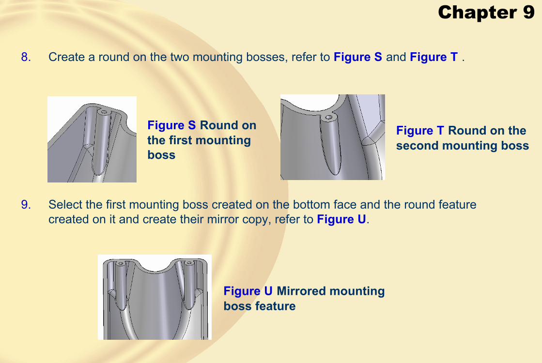
Chapter 9
9. Select the first mounting boss created on the bottom face and the round feature created on it and create their mirror copy, refer to Figure U.
8. Create a round on the two mounting bosses, refer to Figure S and Figure T .
Figure S Round on the first mounting boss
Figure T Round on the second mounting boss
Figure U Mirrored mounting boss feature
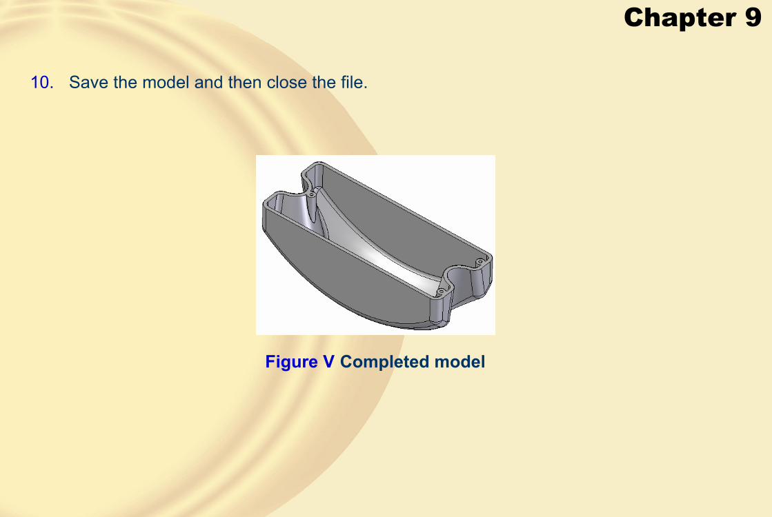
Chapter 9
10. Save the model and then close the file.
Figure V Completed model

Chapter 9
� Exercise 1Create the model shown in Figure A . The dimensions of the model is shown in Figure B.Save the model after creating the model. (Expected time: 30 min)
Figure A Model for Exercise 1 Figure B Drawing views of the model
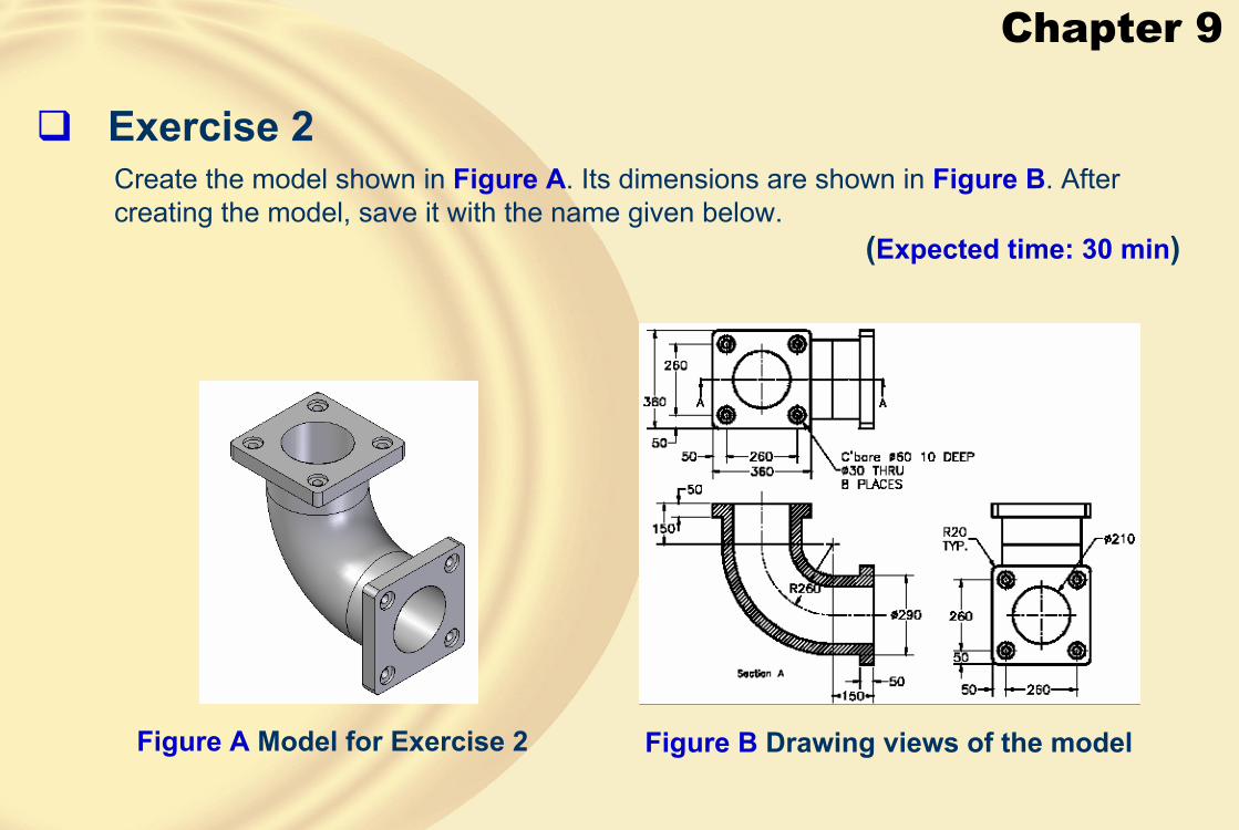
Chapter 9
� Exercise 2Create the model shown in Figure A. Its dimensions are shown in Figure B. After creating the model, save it with the name given below.
(Expected time: 30 min)
Figure A Model for Exercise 2 Figure B Drawing views of the model

Chapter 10
• Understand the Assembly environment.
• Set the Assembly environment to work easily.
• Learn the types of assembly design approaches.
• Create assemblies using the bottom-up approach.
• Understand assembly relationships.
• Create an assembly using the top-down approach.
• Create a pattern of parts in an assembly.
• Create a multipart cutout.
• Move parts in an assembly.
� Learning Objectives
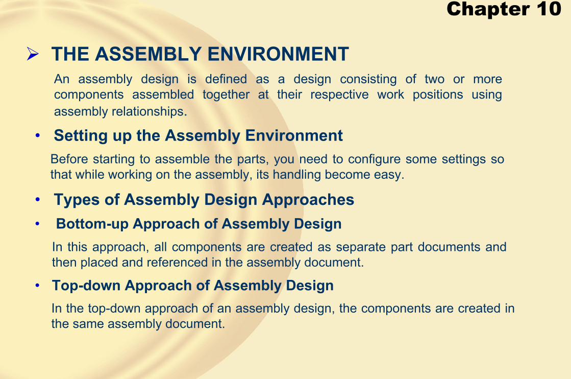
Chapter 10
� THE ASSEMBLY ENVIRONMENT
• Setting up the Assembly Environment
An assembly design is defined as a design consisting of two or more components assembled together at their respective work positions using assembly relationships.
Before starting to assemble the parts, you need to configure some settings so that while working on the assembly, its handling become easy.
• Types of Assembly Design Approaches• Bottom-up Approach of Assembly Design
In this approach, all components are created as separate part documents and then placed and referenced in the assembly document.
• Top-down Approach of Assembly DesignIn the top-down approach of an assembly design, the components are created in the same assembly document.

Chapter 10
The Assembly environment screen

Chapter 10
� CREATING THE BOTTOM-UP ASSEMBLIES• Assembling the First Component in an Assembly
The base component is generally the component that does not have any motion relative to the other components in the assembly
Parts Library button in the EdgeBar
• Assembling the Second Component in an AssemblyTo fully position the second component in the assembly, the assembly relationships relationships are needed.
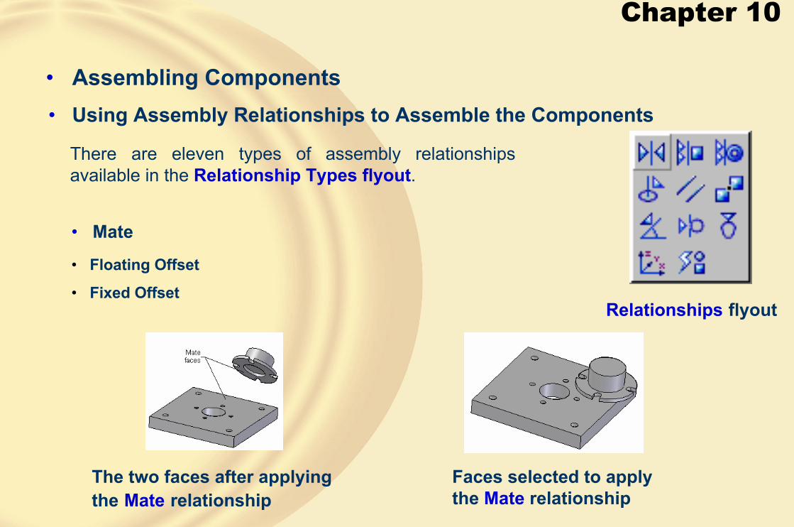
Chapter 10
• Assembling Components• Using Assembly Relationships to Assemble the Components
There are eleven types of assembly relationships available in the Relationship Types flyout.
Relationships flyout
• Mate
• Floating Offset
• Fixed Offset
The two faces after applying the Mate relationship
Faces selected to apply the Mate relationship

Chapter 10
• Planar Align
Faces to be selected The two parts after applying the Planar Align relationship with the fixed offset
• Axial Align
Cylindrical surfaces are selected to align the axes
Bolt assembled with the plate

Chapter 10
The two faces are made parallel by applying the Planar Align relationship with theFloating Offset option
• Insert
• Parallel
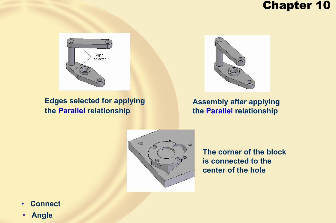
Chapter 10
Assembly after applying the Parallel relationship
Edges selected for applying the Parallel relationship
• Connect• Angle
The corner of the block is connected to the center of the hole
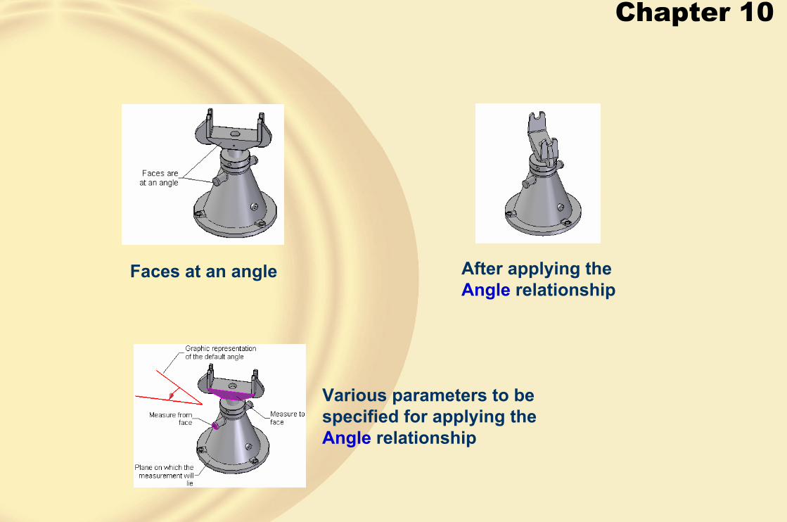
Chapter 10
Faces at an angle After applying the Angle relationship
Various parameters to be specified for applying the Angle relationship
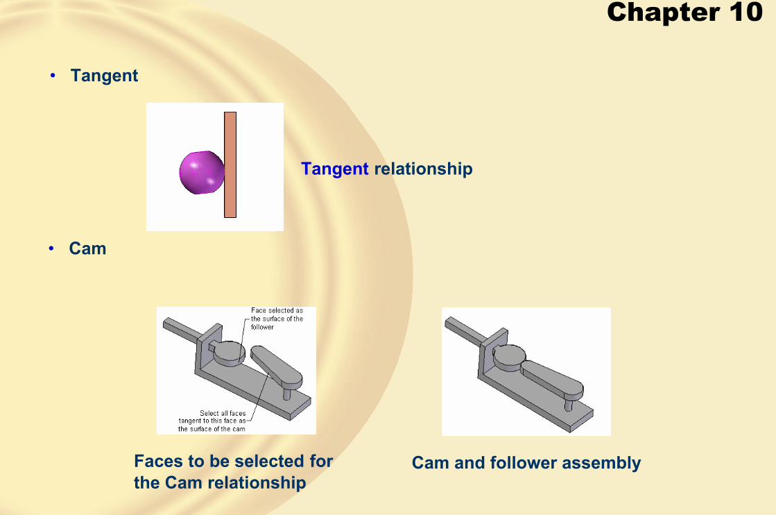
Chapter 10
• Tangent
• Cam
Tangent relationship
Cam and follower assemblyFaces to be selected for the Cam relationship
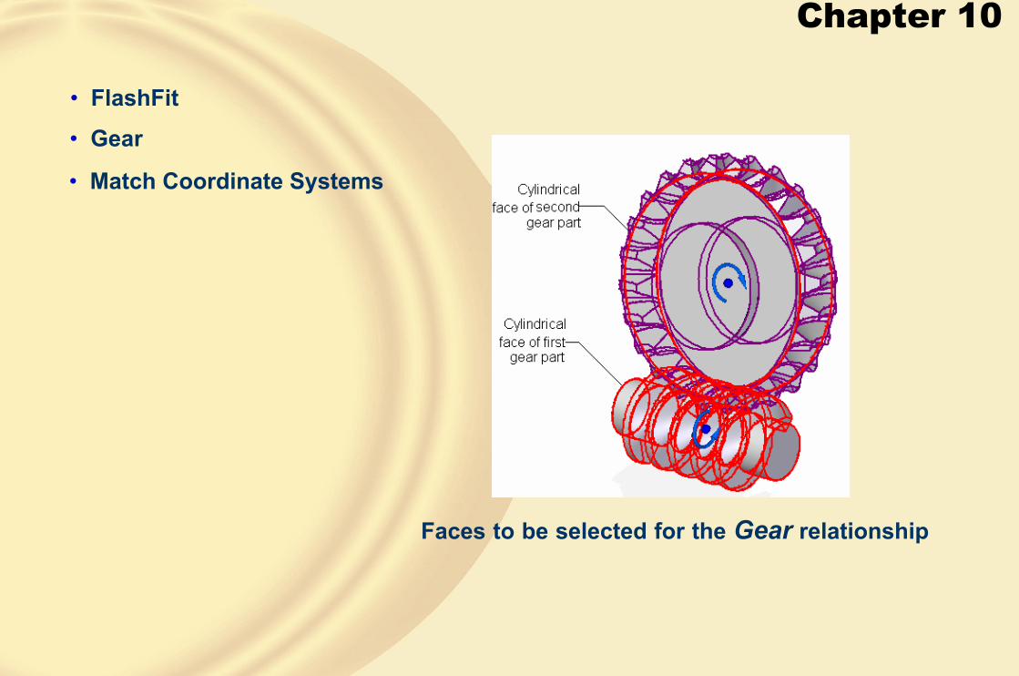
Chapter 10
• FlashFit
• Gear
• Match Coordinate Systems
Faces to be selected for the Gear relationship
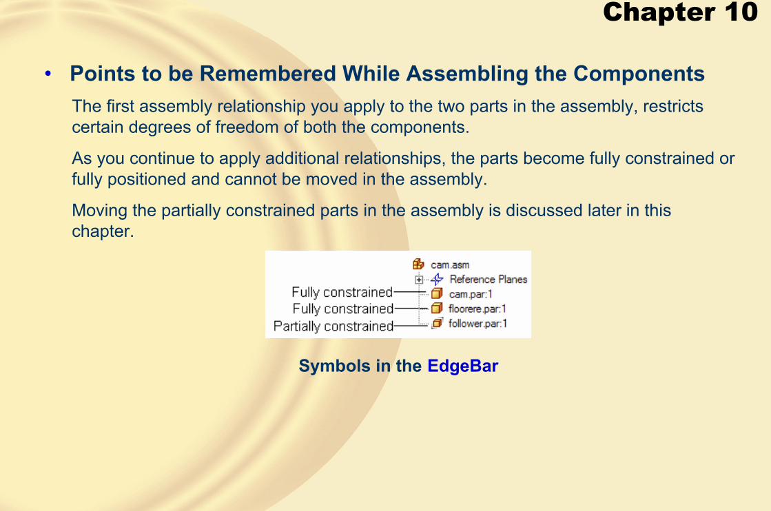
Chapter 10
• Points to be Remembered While Assembling the ComponentsThe first assembly relationship you apply to the two parts in the assembly, restricts certain degrees of freedom of both the components.
As you continue to apply additional relationships, the parts become fully constrained or fully positioned and cannot be moved in the assembly.
Moving the partially constrained parts in the assembly is discussed later in this chapter.
Symbols in the EdgeBar

Chapter 10
It is recommended for beginners that the assembly window should not be maximized.
The Use Reduced Steps when placing parts check box is used to reduce the number of steps to assemble a part with the assembly.
The Options dialog box
When you double-click on a placement part to bring it to the assembly for assembling, it appears in a subwindow.

Chapter 10
Choose the Placement Part-Element button from the ribbon bar, if you have selected an incorrect element on the placement or the target part while applying the assembly relationships.
If after applying one relationship, you apply the second relationship and press the ESC key, the placement part will be assembled with the target part, but without being fully constrained.
To apply relationships to a part that is not fully positioned, select it from theAssembly PathFinder tab in the EdgeBar.
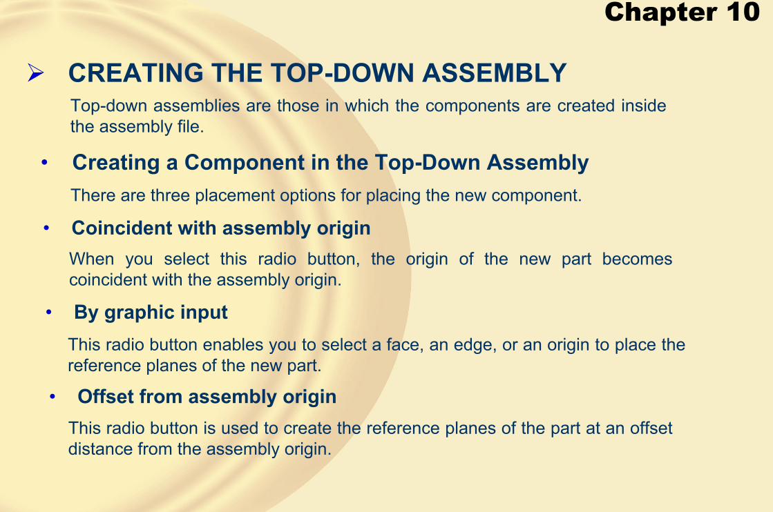
Chapter 10
� CREATING THE TOP-DOWN ASSEMBLY
• Creating a Component in the Top-Down Assembly
Top-down assemblies are those in which the components are created inside the assembly file.
There are three placement options for placing the new component.
• Coincident with assembly origin
• By graphic input
When you select this radio button, the origin of the new part becomes coincident with the assembly origin.
This radio button enables you to select a face, an edge, or an origin to place the reference planes of the new part.
• Offset from assembly originThis radio button is used to create the reference planes of the part at an offset distance from the assembly origin.

Chapter 10
Assembly created using the top-down approach
Chapter 10
� CREATING PATTERN OF COMPONENTS IN AN ASSEMBLY
The reference pattern is used to pattern the instances of the components using an existing pattern feature.
Assembly before creating a pattern Assembly after creating a pattern

Chapter 10
� CREATING MATERIAL REMOVAL FEATURES IN AN ASSEMBLY
• Assembly FeaturesIn Solid Edge, assembly features are the features that are created in theAssembly environment.
• Assembly-Driven Part FeaturesIn Solid Edge, assembly-driven features are the features that are created in theAssembly environment and are associatively linked with the parts that areaffected by this feature.
Dialog box giving you an option

Chapter 10
Three parts to be assembled Parts, after assembling and creating a multipart cutout
The Feature Options dialog box

Chapter 10
� MOVING INDIVIDUAL COMPONENTSProcedure of Moving the Components
You can select any of the three axes and drag the component through Move Part button
Moving the component along the selected axis
Chapter 10
If you want to rotate the component, choose the Rotate button from the ribbon bar and select the axis about which the component’s rotatory movement is free.
Rotating the component using the axes
The Freeform Move button is used to move the selected component in any direction that is free.

Chapter 10
� TUTORIAL 1In this tutorial, you will create all components of the Stock Bracket assembly and then assemble them. The Bracket assembly is shown in Figure A. The dimensions of various components are given in Figures B through H. Note that all dimensions are in inches. After completing the tutorial, save the file. (Expected time: 2 hrs)
Figure A Assembly of the Stock Bracket
Figure B Top and front views of the Stock Support Base

Chapter 10
Figure E Front and right-side views of the Support Roller Bracket
Figure C Top and front views of the Adjusting Screw Nut
Figure D Front and right-side views of the Stock Support Roller

Chapter 10
Figure H Top and front views of the Thrust Bearing
Figure G Views of the Support Adjusting Screw
Figure F Views of the Adjusting Nut Handle and Adjusting Screw Guide

Chapter 10
1. Create all components in individual part files and save them. Note that all dimensions of the parts are in inches. So you need to change the system of units of the new part file you create.
2. Start a new file in the Assembly environment.
3. Select the base component, which is the Stock Support Base, and drag it into the assembly window. This component will automatically assemble with the assembly reference planes, using the Ground relationship.
4. Drag the Thrust Bearing into the assembly window. Apply the required relationships, refer to Figure I.
Figure I After assembling the components
Chapter 10
5. Next assemble the Adjusting Screw Nut with the Thrust Bearing using the assembly relationships, refer to Figure J.
6. Assemble the Support Adjusting Screw with the assembly, refer to Figure K.
Figure J The assembly after assembling the three components
Figure K Assembly after assembling the four components
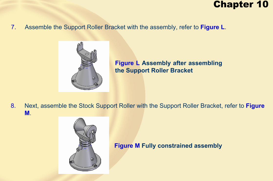
Chapter 10
7. Assemble the Support Roller Bracket with the assembly, refer to Figure L.
8. Next, assemble the Stock Support Roller with the Support Roller Bracket, refer to Figure M.
Figure L Assembly after assembling the Support Roller Bracket
Figure M Fully constrained assembly
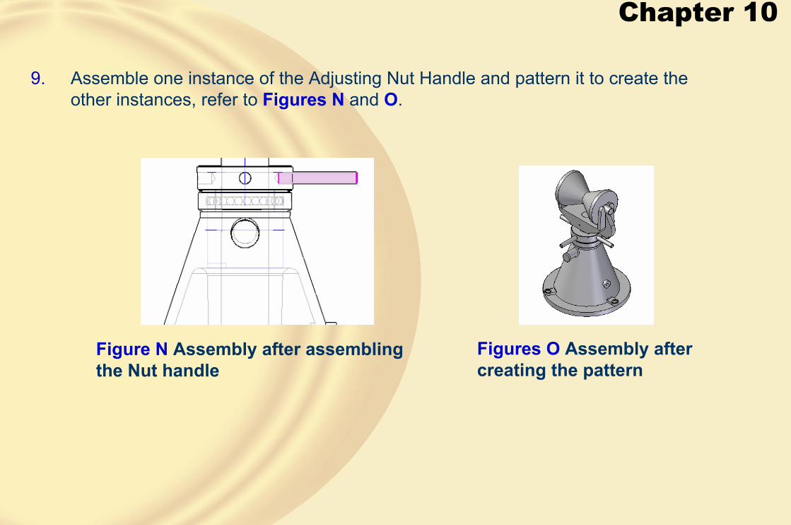
Chapter 10
9. Assemble one instance of the Adjusting Nut Handle and pattern it to create the other instances, refer to Figures N and O.
Figures O Assembly after creating the pattern
Figure N Assembly after assembling the Nut handle

Chapter 10
11. Save the assembly file.
Figure P Completed assembly of Stock Bracket
10. Then assemble the Adjusting Screw Guide with the Stock Support Base, refer to Figure P .

Chapter 10
� TUTORIAL 2In this tutorial, you will create all components of the Pipe Vice and then assemble them. The Pipe Vice assembly is shown in Figure A. The dimensions of components are given in Figures B and C. After completing the tutorial, save the file.
(Expected time: 2 hrs)
Figure A Pipe Vice assembly Figure B Views and dimensions of the Base

Chapter 10
Figure C Views and dimensions of the Screw, Handle, Moveable Jaw, and Handle Screw
1. Create all components in individual part files and save them.
2. Start a new file in the Assembly environment.

Chapter 10
3. Drag the Base into the assembly window. This component will be automatically assembled with the reference planes using the Ground relationship.
4. Drag the Screw into the assembly window and apply the required relationships, refer to Figure D.
Figure D. Two components assembled

Chapter 10
5. Drag the Moveable Jaw into the assembly window and apply the required relationships, refer to Figure E.
6. Drag the Handle into the assembly window and apply the required relationships, refer to Figures F and G.
Figure E Two components assembled
Figure F Reference plane to be selected for mating
Figure G Reference plane on the target part

Chapter 10
7. Drag the Handle Screw into the assembly window and apply the required relationships,refer to Figure H. Similarly, assemble the other instances of the Handle Screw, refer to Figure I.
Figure H Handle Screw assembled at one end of the Handle
Figure I Completed assembly
8. Save the assembly file.

Chapter 10
� Exercise 1Create the Plummer Block assembly, as shown in Figure A. The exploded view of the assembly is shown in Figure B and the bill of material is shown in Figure C. The dimensions of the components of the assembly are shown in Figures D through F. After completing the tutorial save the file.
(Expected time: 2 hrs)
Figure A Plummer Block assembly Figure B Exploded view of the assembly with balloons

Chapter 10
Figure D Views and dimensions of the CastingFigure C Bill of material
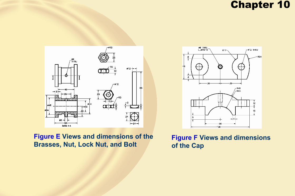
Chapter 10
Figure F Views and dimensions of the Cap
Figure E Views and dimensions of the Brasses, Nut, Lock Nut, and Bolt
Chapter 11
Learning Objectives:• Create subassemblies.
• Edit assembly relationships.
• Edit assembly components.
• Disperse the assembly.
• Replace components in an assembly.
• Set the visibility options of the assembly.
• Check interference in an assembly.
• Create the exploded state of the assembly.

Chapter 11
� CREATING SUBASSEMBLIESSometimes when an assembly has many parts, it becomes easy to design it by segregating it into subassemblies.
A subassembly of articulated rod and piston
A subassembly of master rod and piston
Main assembly after assembling the subassemblies

Chapter 11
� EDITING ASSEMBLY RELATIONSHIPSThe editing operations that can be performed on the assembly relationships are:
• Modifying the Values
• Applying Additional Relationships
• Select the part from the EdgeBar.• Select a mate relationship from the bottom pane.
• Enter a new offset value in the Offset Value edit box on the EditRelationships ribbon bar.
• Choose the OK button to incorporate the changes.
• Select the partially positioned part from the EdgeBar.
• Choose the Edit Definition button from the Assembly Selection ribbon bar.
• Choose the assembly relationship from the Relationship Types flyout to apply new relationships to the part.

Chapter 11
• Modifying the Assembly Relationships
Symbols that are displayed in the EdgeBar
Symbols of relationships
• Sometimes you may need to modify the existing assembly relationships of parts in an assembly.
• For example, you may need to modify a mate relationship to a planar align relationship.
• The table above shows Symbols of relationships.
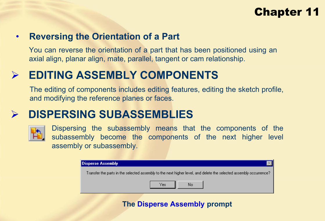
Chapter 11
• Reversing the Orientation of a PartYou can reverse the orientation of a part that has been positioned using an axial align, planar align, mate, parallel, tangent or cam relationship.
� EDITING ASSEMBLY COMPONENTSThe editing of components includes editing features, editing the sketch profile, and modifying the reference planes or faces.
� DISPERSING SUBASSEMBLIESDispersing the subassembly means that the components of the subassembly become the components of the next higher level assembly or subassembly.
The Disperse Assembly prompt

Chapter 11
� REPLACING COMPONENTSThis is used to replace a component of the assembly with some other component.
The Replace Part prompt
� SIMPLIFYING ASSEMBLIES USING THE VISIBILITYOPTIONS• By simplifying, you can hide the components at any stage of the design cycle.
• The methods of simplifying the assembly are:
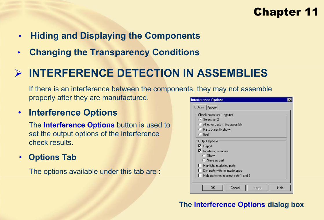
Chapter 11
• Hiding and Displaying the Components
• Changing the Transparency Conditions
� INTERFERENCE DETECTION IN ASSEMBLIESIf there is an interference between the components, they may not assemble properly after they are manufactured.
• Interference OptionsThe Interference Options button is used to set the output options of the interference check results.
The Interference Options dialog box
• Options TabThe options available under this tab are :
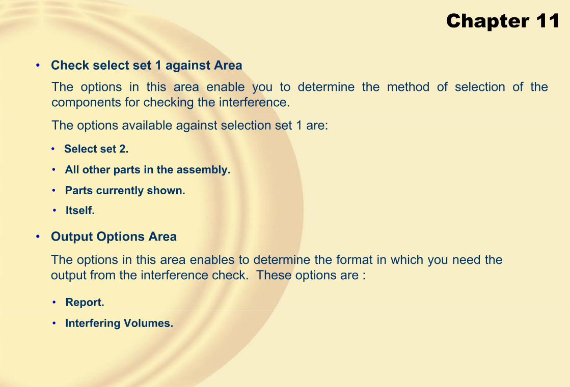
Chapter 11
• Check select set 1 against AreaThe options in this area enable you to determine the method of selection of the components for checking the interference.
The options available against selection set 1 are:
• Select set 2.
• All other parts in the assembly.
• Parts currently shown.
• Itself.
• Output Options Area
The options in this area enables to determine the format in which you need the output from the interference check. These options are :
• Report.
• Interfering Volumes.
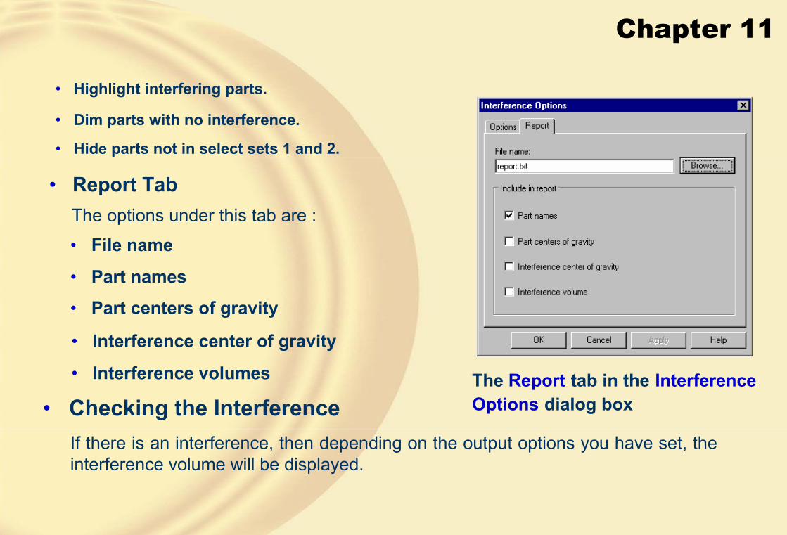
Chapter 11
• Highlight interfering parts.
• Dim parts with no interference.
• Hide parts not in select sets 1 and 2.
• Report TabThe options under this tab are :
The Report tab in the InterferenceOptions dialog box
• File name
• Part names
• Part centers of gravity
• Interference center of gravity
• Interference volumes
• Checking the InterferenceIf there is an interference, then depending on the output options you have set, the interference volume will be displayed.

Chapter 11
� CREATING EXPLODED STATE OF ASSEMBLIES• Automatic Explode
The first option is to automatically create the exploded view.
All
Assemblies
Selected
Not Selected
To unexplode the assembly, choose the Unexplode button from the Exploded View toolbar.
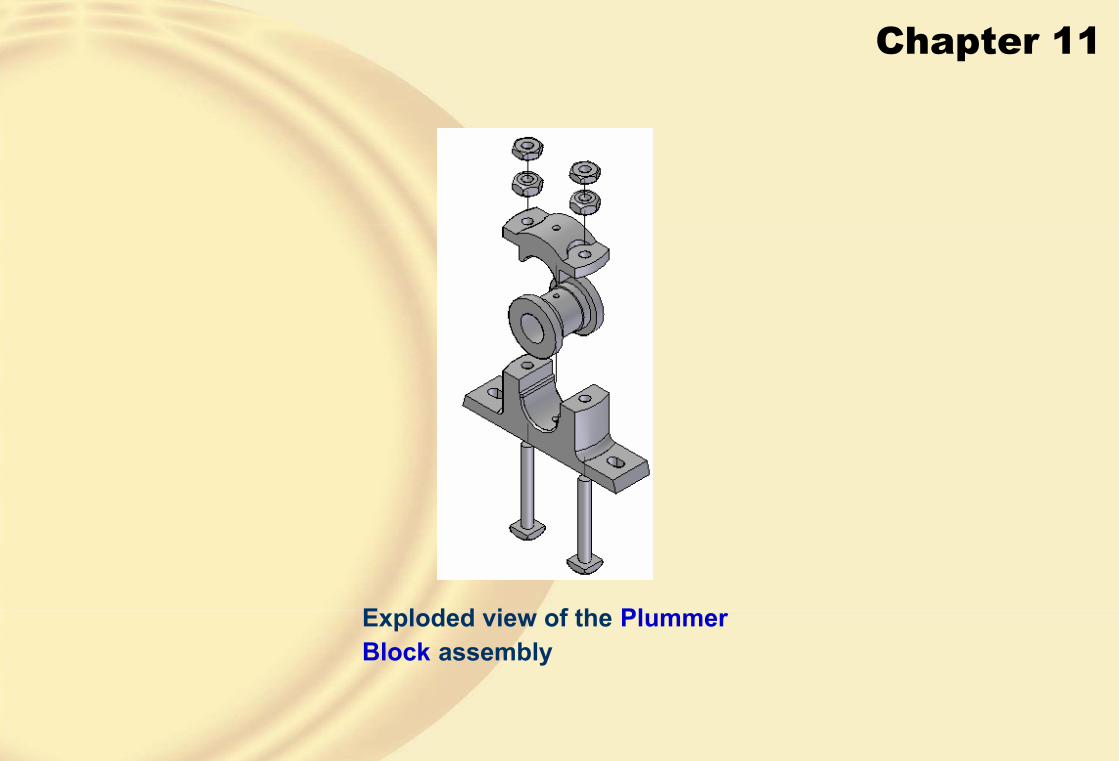
Chapter 11
Exploded view of the PlummerBlock assembly

Chapter 11
• Manual ExplodeThe automatic explode method does not give the desired results every time, therefore the manual method is used to achieve the desired explode state.
Exploded state

Chapter 11
• Changing the Distance Between the Components
• Repositioning the Parts
• Removing the Parts
• FlowlinesThe Flowlines indicate the direction of explosion of the component.
Exploded state without Flowlines Exploded state with Flowlines

Chapter 11
In this tutorial, you will create the exploded view of the Plummer Block assembly created in Exercise 1 of Chapter 10. The exploded state of the assembly is shown in Figure A. After creating the exploded state, save the configuration.
(Expected Time: 15 min)
� TUTORIAL 1
Figure A Exploded view of the Plummer Block assembly
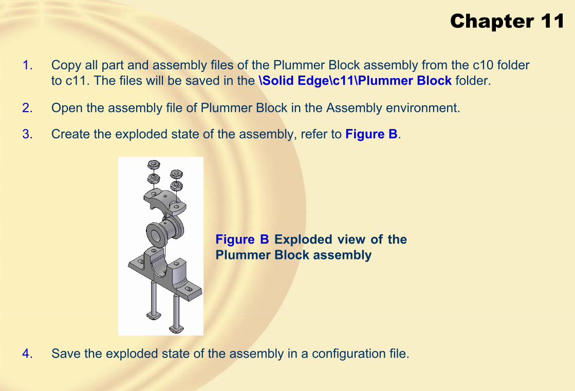
Chapter 11
4. Save the exploded state of the assembly in a configuration file.
1. Copy all part and assembly files of the Plummer Block assembly from the c10 folder to c11. The files will be saved in the \Solid Edge\c11\Plummer Block folder.
2. Open the assembly file of Plummer Block in the Assembly environment.
3. Create the exploded state of the assembly, refer to Figure B.
Figure B Exploded view of the Plummer Block assembly
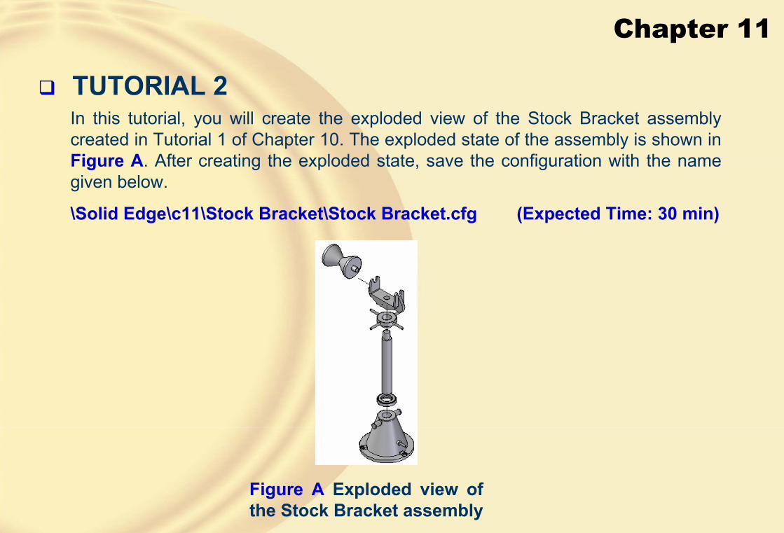
Chapter 11
� TUTORIAL 2In this tutorial, you will create the exploded view of the Stock Bracket assembly created in Tutorial 1 of Chapter 10. The exploded state of the assembly is shown in Figure A. After creating the exploded state, save the configuration with the name given below.
\Solid Edge\c11\Stock Bracket\Stock Bracket.cfg (Expected Time: 30 min)
Figure A Exploded view of the Stock Bracket assembly

Chapter 11
1. Copy files to the current folder.
2. Create the exploded state Figure B.
Figure B Exploded view of the Stock Bracket assembly
3. Collapse the component Figure C.
Figure C Exploded view after collapsing the Stock Support Roller
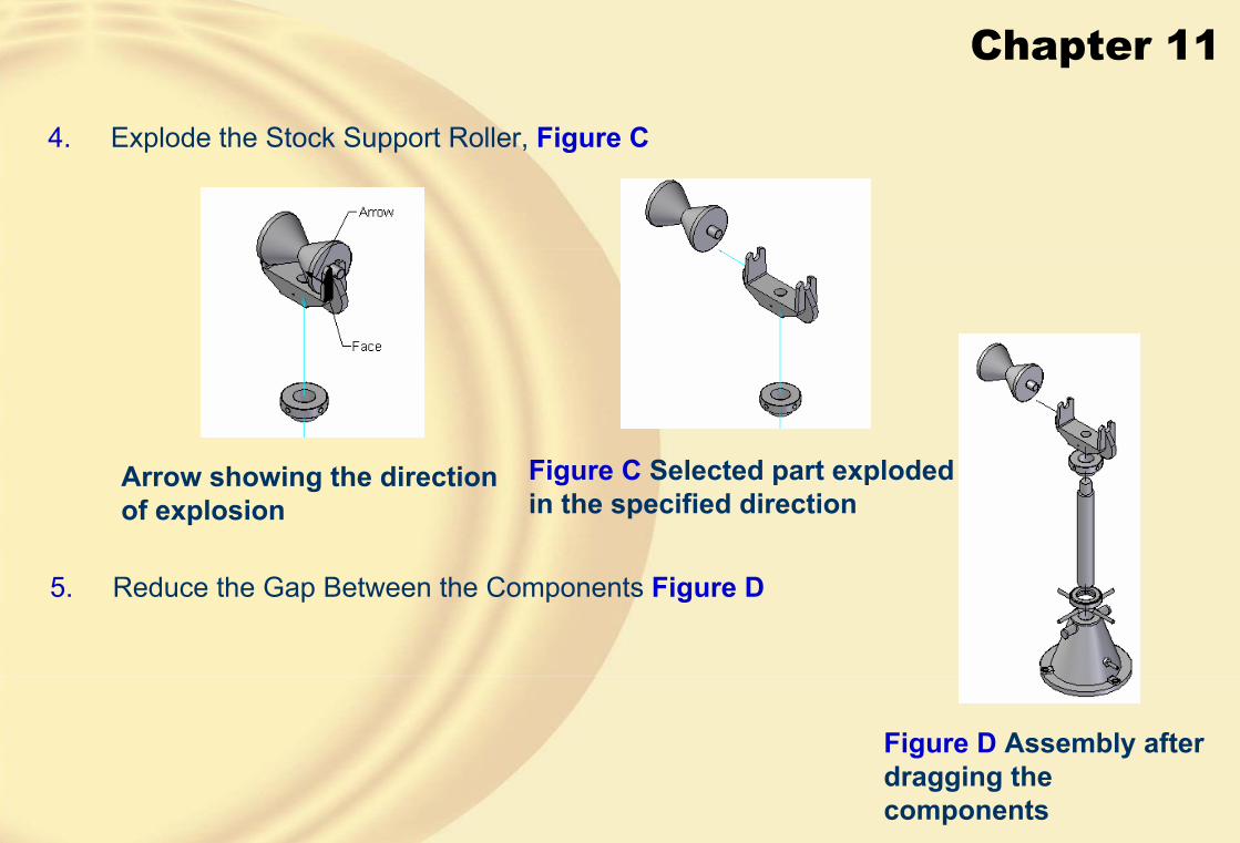
Chapter 11
4. Explode the Stock Support Roller, Figure C
Figure C Selected part exploded in the specified direction
Arrow showing the direction of explosion
5. Reduce the Gap Between the Components Figure D
Figure D Assembly after dragging the components

Chapter 11
6. Move the Components
Selected part placed at the required position
Moving the component along the vertical axis
Assembly after moving all instances of the Adjusting Nut Handle
Adjusting Nut Handle after dragging

Chapter 11
7. Explode the Last Component
Selected part exploded in the specified direction
Arrow showing the direction of explosion
8. Saving the Configuration

Chapter 11
� TUTORIAL 3In this tutorial, you will create the assembly shown in Figure A. This assembly will be created in two parts, the subassembly and the main assembly. The exploded state of the assembly is shown in Figure B. The views and dimensions of all components of this assembly are shown in Figures C through F. After creating the assembly, save it with the name given below.
\Solid Edge\c11\Radial Engine\radial engine.asm (Expected time: 3 hrs)
Figure A The radial engine assembly Figure B Exploded view of the assembly
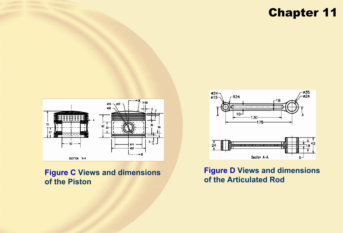
Chapter 11
Figure C Views and dimensions of the Piston
Figure D Views and dimensions of the Articulated Rod

Chapter 11
Figure F Views and dimensions of the Master Rod
Figure E Views and dimensions of other components

Chapter 11
1. Create the Components
2. Create the Subassembly
Subassembly after assembling and changing the color of Piston Rings
First instance of the Piston Ring assembled with the Piston
Assembly sequence of the Articulated Rod, Piston, Piston Pin Plug, Rod Bush Upper, and Rod Bush Lower

Chapter 11
3. Create the main assembly
Main assembly
4. Assemble the Subassembly with the Main Assembly
First instance of the subassembly assembled with the main assembly

Chapter 11
5. Assemble the Link Pin
Assembly structure
All instances of the Link Pin assembled with the main assembly
First instance of the Link Pin assembled with the assembly

Chapter 11
� Exercise 2Create the Shaper Tool Head assembly shown in Figure A. After creating the assembly, create its exploded state, as shown in Figure B. The dimensions of the model are given in Figures C to G. After creating the assembly, save it with the name given below.
\Solid Edge\c11\Shaper Tool Head\shaper.asm (Expected time: 4 hr)
Figure A Shaper Tool Holder assembly
Figure B Exploded state of the assembly

Chapter 11
Figure C Views and dimensions of the Back Plate
Figure D Views and dimensions of the Vertical Slide

Chapter 11
Figure E Views and dimensions of the Swivel Plate
Figure F Views and dimensions of various components
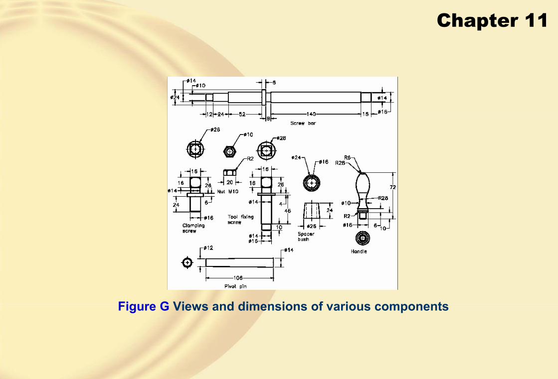
Chapter 11
Figure G Views and dimensions of various components
Chapter 12
Learning Objectives:• Understand the Draft environment.
• Learn the types of views that can be generated in Solid Edge.
• Generate drawing views.
• Manipulate drawing views.
• Add annotations to drawing views.
• Generate exploded views of assemblies.
• Create associative balloons and parts list.

Chapter 12
Solid Edge has a separate environment called the Draft environment,which is used for generating drawing views.
� THE DRAFT ENVIRONMENT
Selecting a draft template from the New dialog box
The default screen display in theDraft environment
Chapter 12
� TYPES OF VIEWS THAT CAN BE GENERATED IN SOLIDEDGE
• Base View
• Principal View
• Auxiliary View
• Section View
• Detail View
• Broken-Out View
In Solid Edge, there are two types of drafting techniques: generative drafting and interactive drafting.
In the generative drafting, the views are generated from the part or assembly that is already created.
In the interactive drafting, the views are sketched using the sketching tools.

Chapter 12
� GENERATING DRAWING VIEWS• Generating the Base View
From the Select Model dialog box, select the model whose drawing views you need to generate and choose the Open button; the Drawing View CreationWizard dialog box will be displayed, as shown in the figure.
Part/Sheet Metal Drawing View Options page of the Drawing View Creation Wizard dialog box

Chapter 12
• Part/Sheet Metal Drawing View Options PageThe options in this page enable you to specify the parameters related to the display of the drawing view.
• Designed Part
This radio button is selected by default and is used to specify that you need to generate the drawing views of an existing part.
• Simplified Part
This radio button is used to generate the drawing views of the simplified version of a model.
• Flat Pattern
This radio button is used to generate the drawing views of a flat pattern of the sheet metal part.

Chapter 12
• Show hidden edges in Orthographic viewsThis check box is selected by default and is used to display the hidden edges, if any, in the orthographic drawing views.
• Show hidden edges in Pictorial views
Drawing view with hidden edges Drawing view without hidden edges
• Show tangent edges in Orthographic views
This option is used to display the tangent edges, if any in the part, in the orthographic drawing views.

Chapter 12
• Show tangent edges in Pictorial viewsThis option is used to display the tangent edges, if any, in the pictorial drawing views.
• Drawing View Orientation Page
When you choose the Next button from the Part/Sheet Metal Drawing View Optionspage, the Drawing View Orientation area will be displayed, as shown in the figure.
Drawing View Orientation page of the Drawing View Creation Wizard dialog box
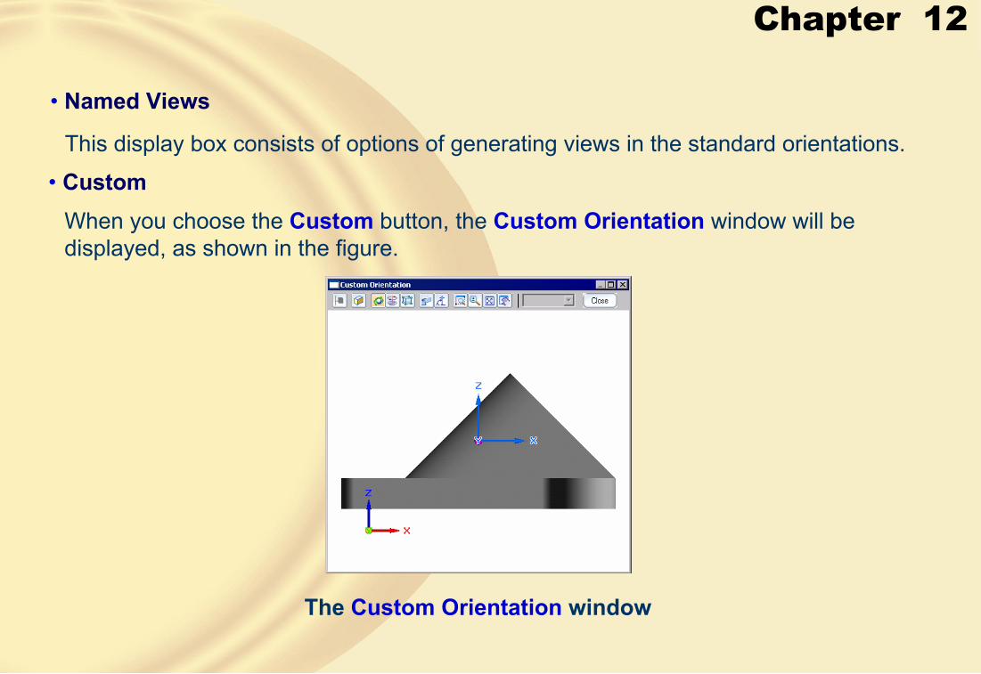
Chapter 12
• Named Views
This display box consists of options of generating views in the standard orientations.
• CustomWhen you choose the Custom button, the Custom Orientation window will be displayed, as shown in the figure.
The Custom Orientation window
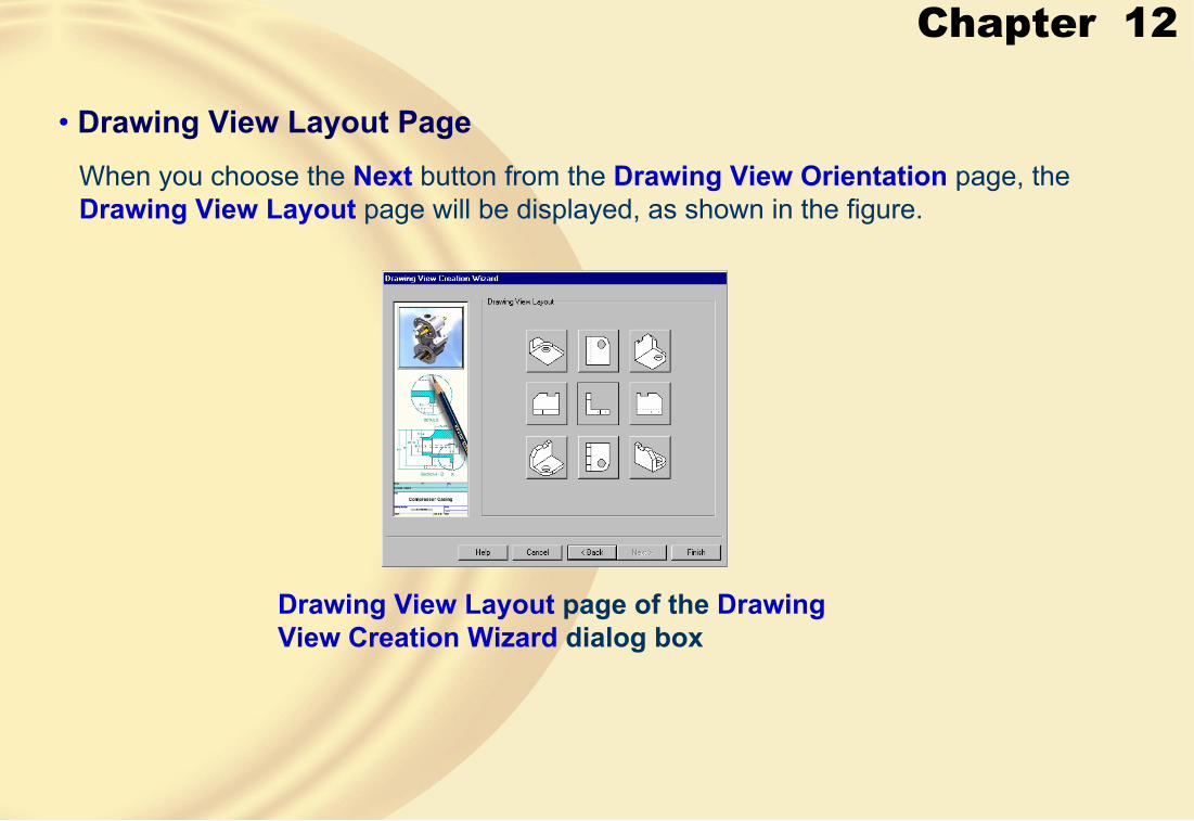
Chapter 12
• Drawing View Layout PageWhen you choose the Next button from the Drawing View Orientation page, the Drawing View Layout page will be displayed, as shown in the figure.
Drawing View Layout page of the DrawingView Creation Wizard dialog box

Chapter 12
• Generating the Principal ViewThe principal view is generated by selecting an existing view. This view can be a base view or another principal view.
Drawing sheet with the base view and principal views

Chapter 12
• Generating the Auxiliary ViewThe auxiliary view is a drawing view that is generated by projecting the lines normal to a specified edge of an existing view.
Auxiliary view from the principal view
Partial view of the Viewing Plane Properties dialog box
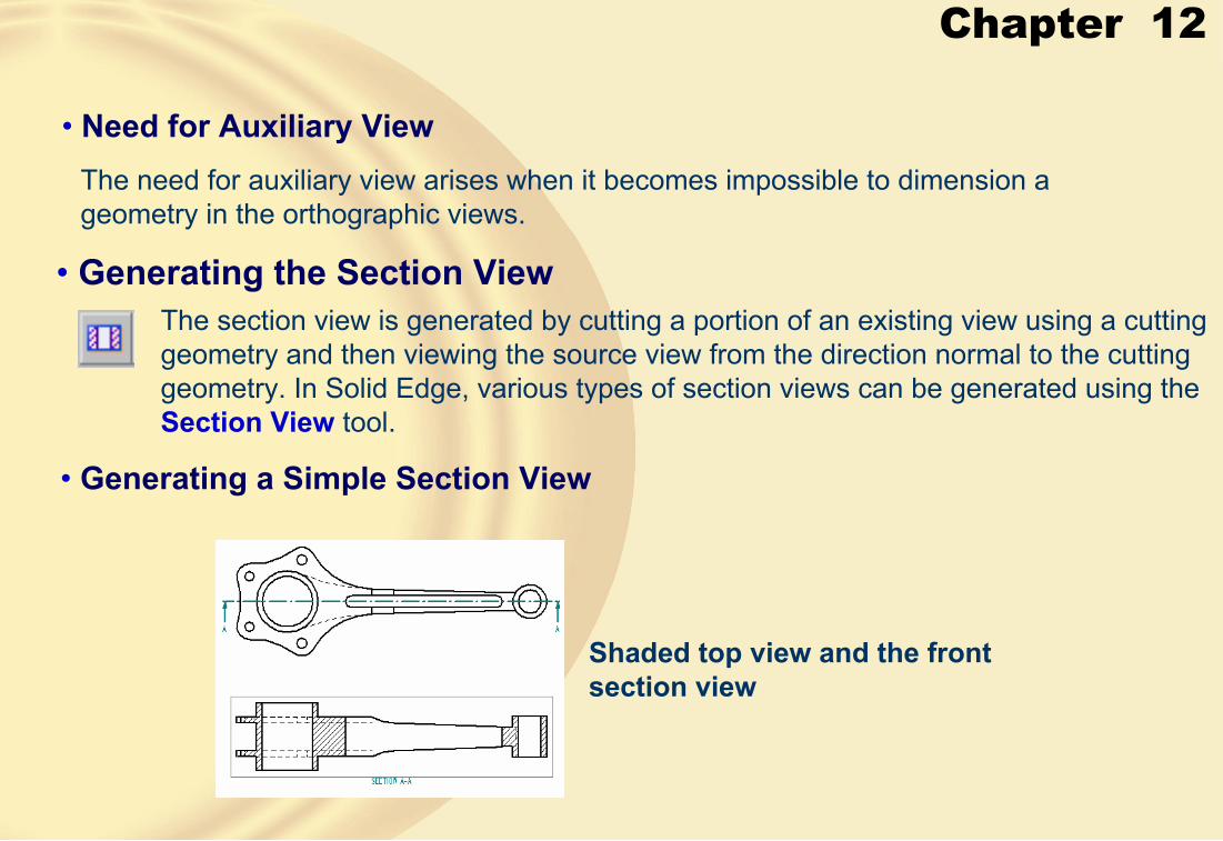
Chapter 12
• Need for Auxiliary ViewThe need for auxiliary view arises when it becomes impossible to dimension a geometry in the orthographic views.
• Generating the Section ViewThe section view is generated by cutting a portion of an existing view using a cutting geometry and then viewing the source view from the direction normal to the cutting geometry. In Solid Edge, various types of section views can be generated using the Section View tool.
• Generating a Simple Section View
Shaded top view and the front section view

Chapter 12
• Points to Remember for Creating the Cutting Planes• The sketch drawn can be a combination of arcs and lines.
• The sketch must be open and all entities should be connected to each other.
• Relationships and dimensions between the sketch entities and the drawing view can be applied.
• The cutting plane can be edited either by double-clicking on it or by choosing the Edit button, which will be displayed in the ribbon bar when you select the cutting plane.
• Revolved Section Views• The revolved section views are needed when some features in a model are at a
certain angle.
• In a revolved section view, the section portion revolves around an axis normal to the viewing plane such that it is straightened.

Chapter 12
Front view and the right-side revolved section view
Two different revolved section views generated by selecting two different cutting geometries
• Section View that Displays only the Section Geometry
Section view displaying only the section area

Chapter 12
• Generating the Broken-Out Section View
Specifying the profile and the depth of the cut
Isometric broken section view
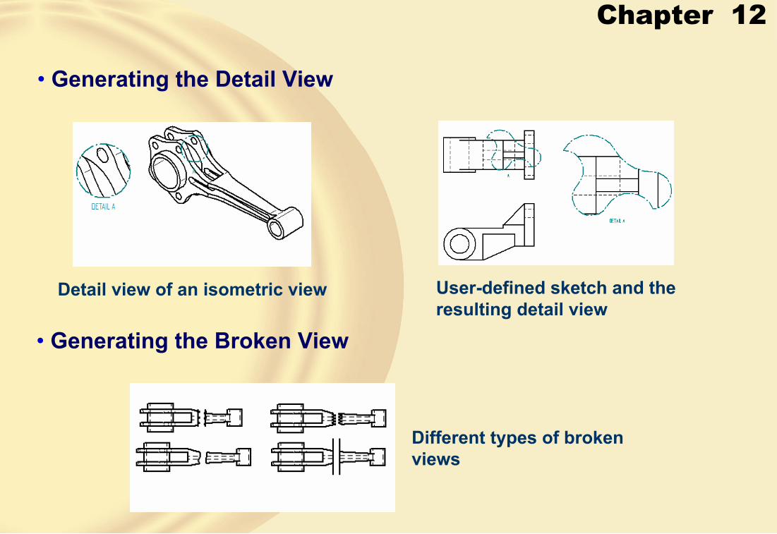
Chapter 12
• Generating the Detail View
Detail view of an isometric view User-defined sketch and the resulting detail view
• Generating the Broken View
Different types of broken views

Chapter 12
� WORKING WITH INTERACTIVE DRAFTING• In technical terms, sketching 2D drawing views is known as interactive drafting.
• The 2D drawing views can be drawn by choosing the Draft View button from the Drawing Views toolbar, after customizing the toolbar to add this button.
� MANIPULATING THE DRAWING VIEWS• Aligning the Drawing Views
• When you generate the principal views from the base views, they are aligned automatically.
• If you move one of the views, then the other view will also move along with the first view.

Chapter 12
• Modifying the Scale of Drawing ViewsYou can modify the scale of a drawing view by selecting it and choosing the Properties button from the ribbon bar.
• Cropping the Drawing Views• A drawing view is cropped to show a particular portion of the drawing view that
already exists on the drawing sheet.
• The portion of the view that lies inside the associated box is retained and the remaining portion is removed.
• Moving the Drawing ViewsTo move a drawing view, select it and drag it on the drawing sheet.
• Rotating the Drawing ViewsThe drawing views can be rotated by invoking the Drawing toolbar.

Chapter 12
• Applying the Hatch PatternTo apply the hatch pattern, choose the Fill button from the Drawing toolbar; you will be prompted to select the area.
• Modifying the Properties of Drawing Views• To set the properties, right-click on the drawing
view to invoke the shortcut menu.
• Choose the Properties option to display the Drawing View Properties dialog box, as shown in the figure.
The View Properties dialog box for a principal view

Chapter 12
� ADDING ANNOTATIONS TO THE DRAWING VIEWSOnce you have generated the drawing views, you need to add annotations, such as dimensions, notes, surface finish symbols, geometric tolerances, and so on.
• Generating AnnotationsGenerating annotations is the process of retrieving dimensions, notes, and so on from the parent model.
• Dimension Style MappingThis button is a toggle and is used to specify whether or not the dimension style mapping set using the Dimension Style tab of the Options dialog box will be used.
• Linear• Radial• Angular• Annotations
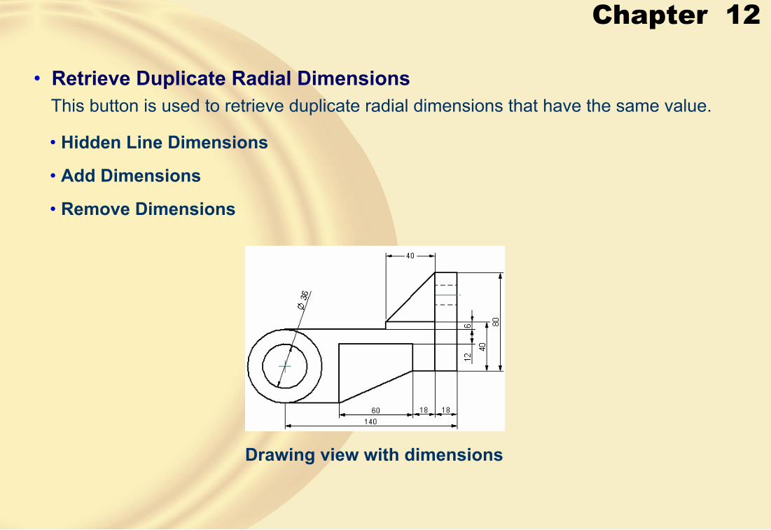
Chapter 12
• Retrieve Duplicate Radial DimensionsThis button is used to retrieve duplicate radial dimensions that have the same value.
• Hidden Line Dimensions
• Add Dimensions
• Remove Dimensions
Drawing view with dimensions
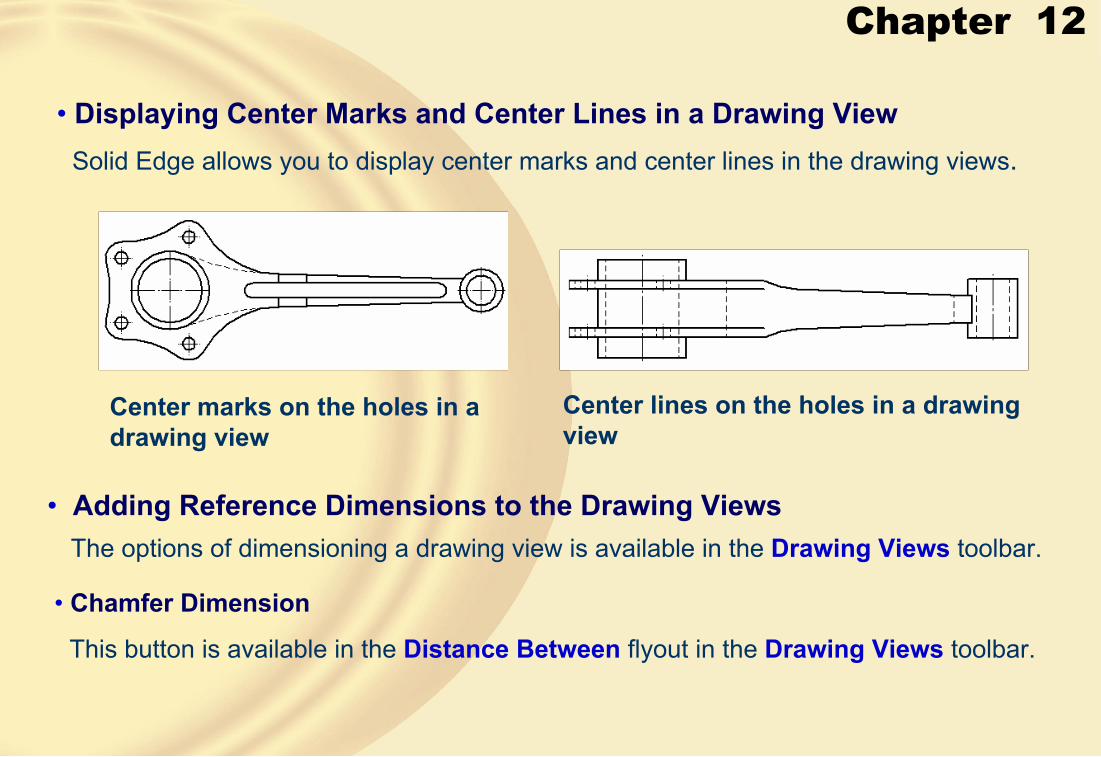
Chapter 12
• Displaying Center Marks and Center Lines in a Drawing ViewSolid Edge allows you to display center marks and center lines in the drawing views.
Center marks on the holes in a drawing view
Center lines on the holes in a drawing view
• Adding Reference Dimensions to the Drawing ViewsThe options of dimensioning a drawing view is available in the Drawing Views toolbar.
• Chamfer Dimension
This button is available in the Distance Between flyout in the Drawing Views toolbar.

Chapter 12
� ADDING NEW DRAWING SHEETS• In Solid Edge, a drawing file can have multiple drawing sheets.
• A multisheet drawing file is generally used when you need to generate drawing views of all parts of an assembly in a single drawing file.
� EDITING THE DEFAULT SHEET FORMATYou can edit the default standard sheet format according to your design requirement.
� GENERATING EXPLODED VIEWS OF ASSEMBLIESThe exploded views are generated by selecting the configuration that was saved at the time of exploding the assembly in the Assembly environment.
Exploded view

Chapter 12
When you choose the Model Display Settings button, the Drawing View Properties dialog box will be displayed, as shown in the figure.
Drawing View Propertiesdialog box
• Drawing View Properties Dialog BoxThis dialog box contains various options of controlling the display of the assembly drawing view.
• ShowUsing the Show check box, you can control the display of one or more parts in the assembly.
• Display as ReferenceThis check box, when selected, enables you to display the selected part as reference.
• Visible edge styleThis drop-down list enables you to select the edge style of the parts in the assembly drawing view.

Chapter 12
� CREATING ASSOCIATIVE BALLOONS AND PARTS LISTGenerally, the drawing view of an assembly also contains the list of parts, the material of each part, the quantity, and other related information in the form of a table, which is called the bill of material (BOM).
In Solid Edge, it is called the parts list.
Exploded view of the assembly with BOM and balloons

Chapter 12
• List Properties Dialog BoxWhile generating the parts list on the drawing sheet and before selecting the Finishbutton, when you choose the Properties button from the ribbon bar, the List Propertiesdialog box will be displayed, as shown in the figure.
List Properties dialog box

Chapter 12
• General Tab• Save settings
This drop-down list contains the styles that are saved for the parts list.
• Text Area
This area provides the options that are used to set the properties of the text.
• SheetThis drop-down list is used to specify the sheet on which you want to place the parts list.
• Mark un-ballooned items
This check box is selected by default.
This indicates that if a balloon is not attached to any part of the assembly, then that part in the parts list will be marked by an asterisk.

Chapter 12
• Size/Placement Tab• Title block
Using this drop-down list, you can specify the location of the title block in the parts list.
• Maximum height of list
You can specify the maximum height of the parts list using this edit box.
• Section gap
This edit box is used to specify the gap between the different sections of the parts list.
• Grid color
This drop-down list is used to specify the color of the lines that make up the parts list.
• Grid line widthThis edit box is used to specify the width of the lines in the parts list.

Chapter 12
• Text margin
The value in this edit box specifies the gap between the lines and the text in the parts list.
• Location AreaThe options in this area are used to specify the location of the parts list on the drawing sheet.
• Columns Tab• Available columns
This display box lists all the column headings that you can display in the parts list.
• Columns usedThis display box lists all the columns that will appear in the parts list.
• Column Format AreaThe options in this area are used to specify a different title for the column heading selected from the Columns used display box.
Chapter 12
• Component Types Tab
• Sorting TabThe options under this tab are used to specify the criteria to sort the parts in the parts list.
The options under this tab are used to specify the type of components to be included in the parts list.
• List Control TabThe options under this tab are used to specify the display of parts in the parts list.
• Top-level list (top-level and expanded components)
• Atomic List (all parts)
• Selected item Area
• Sub-assemblies Area
• Include only ballooned parts
• Exclude hidden parts
• Exclude reference parts
Chapter 12
• Balloon TabThe options under this tab enable you to set the display properties of the balloons that appear on the assembly drawing view.
• Steps to Generate Parts List and Balloons• Choose the Parts List button from the Drawing Views toolbar; you are prompted to select
the drawing view.
• Select the drawing view that exists on the drawing sheet.
• Choose the Properties button from the ribbon bar to display the List Properties dialog box.
• Choose the Columns tab.• In the Columns used display box, select Document Number and choose the Remove
button.
• Choose the List Control tab.
• From the Global area, select the Atomic List (all parts) radio button and choose the OK button to exit the dialog box.
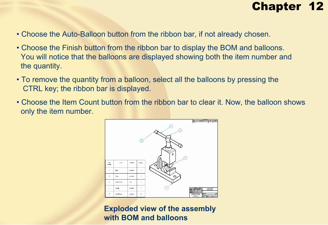
Chapter 12
Exploded view of the assembly with BOM and balloons
• Choose the Auto-Balloon button from the ribbon bar, if not already chosen.
• Choose the Finish button from the ribbon bar to display the BOM and balloons. You will notice that the balloons are displayed showing both the item number and the quantity.
• To remove the quantity from a balloon, select all the balloons by pressing the CTRL key; the ribbon bar is displayed.
• Choose the Item Count button from the ribbon bar to clear it. Now, the balloon shows only the item number.

Chapter 12
� Tutorial 1In this tutorial, you will generate the top view, front view, and the right-side view of the part that was created in Exercise 1 of Chapter 8 and is shown in Figure A. Use the standard A4 Landscape sheet format for generating the drawing views. You will also insert your company logo in the sheet. (Expected time: 1 hr)
Figure A Top, front, right-side, and isometric views of the model

Chapter 12
1. Start a new draft file.
2. Set up the drawing sheet and the background sheet, as shown in Figure B and Figure C.
Figure B Selecting the table Figure C Title block with the image
3. Set the projection angle method.

Chapter 12
4. Generate the drawing views, as shown in Figure D and Figure E.
Figure D Drawing View Layout area of the Drawing View Creation Wizard
Figure E Sheet after generating all the drawing views
5. Save the file in \My Documents\Solid Edge\c12\c12tut2.par and then close it.

Chapter 12
� Tutorial 2In this tutorial, you will generate the front view, left-side view, and the auxiliary view of the part that was created in Exercise 1 of Chapter 8. You will also generate the dimensions, as shown in Figure A. Use the template that was created in Tutorial 1.
(Expected time: 30 min)
Figure A Left-side view, auxiliary view, and the front view of the model
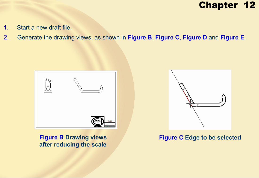
Chapter 12
1. Start a new draft file.2. Generate the drawing views, as shown in Figure B, Figure C, Figure D and Figure E.
Figure B Drawing views after reducing the scale
Figure C Edge to be selected

Chapter 12
3. Generate the dimensions.
Figure D Moving the cursor to place the view
Figure E Drawing sheet after generating the auxiliary view

Chapter 12
4. Create the remaining dimensions that are not generated, as shown in Figure F, Figure G, Figure H and Figure I.
Figure F Front view after placing the angular dimension
Figure G Axis drawn to dimension
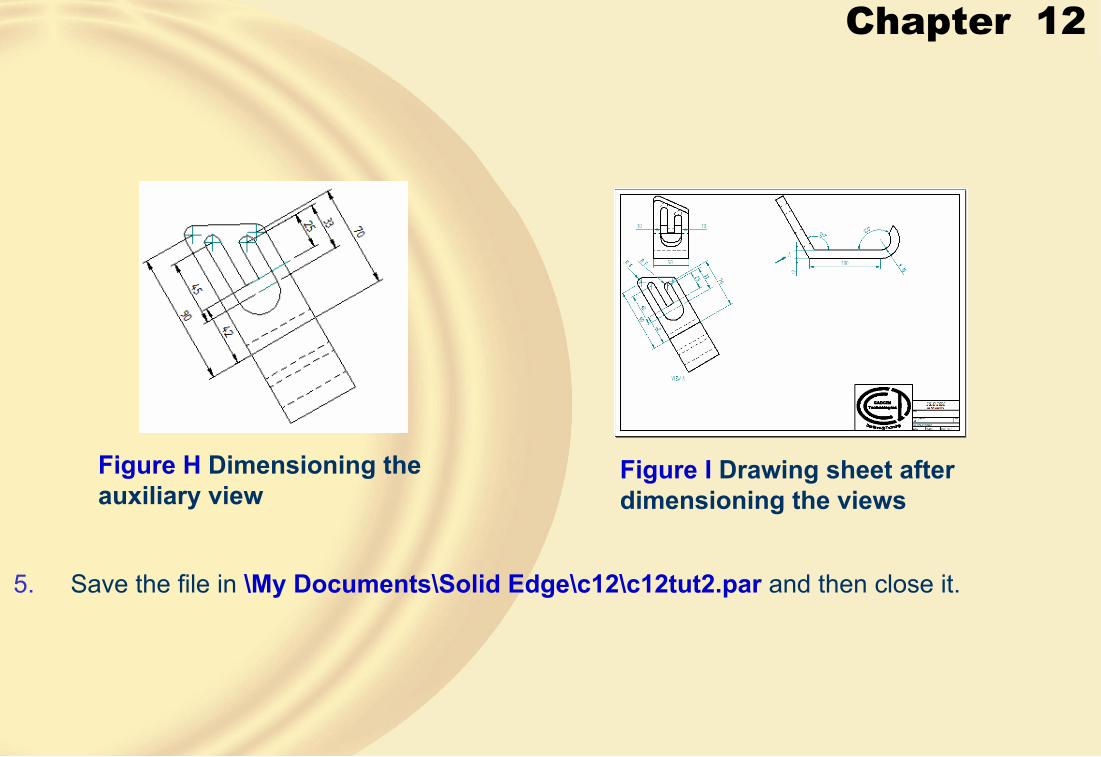
Chapter 12
Figure H Dimensioning the auxiliary view
Figure I Drawing sheet after dimensioning the views
5. Save the file in \My Documents\Solid Edge\c12\c12tut2.par and then close it.
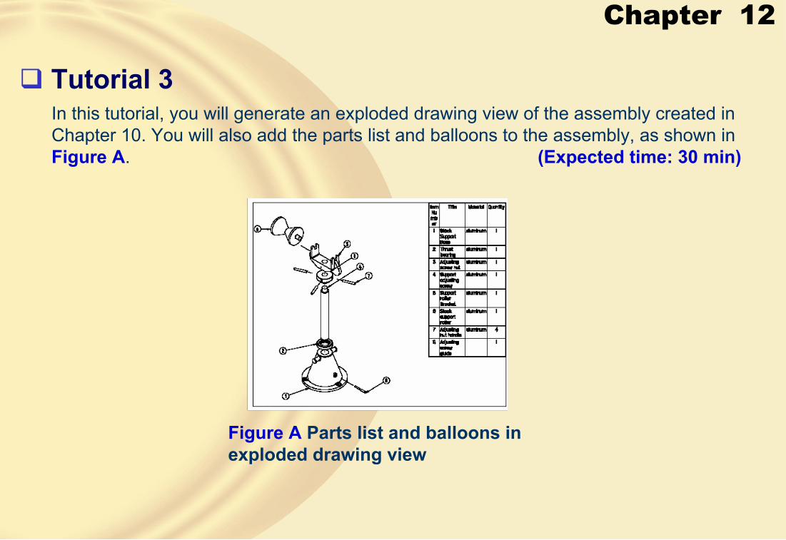
Chapter 12
� Tutorial 3In this tutorial, you will generate an exploded drawing view of the assembly created in Chapter 10. You will also add the parts list and balloons to the assembly, as shown in Figure A. (Expected time: 30 min)
Figure A Parts list and balloons in exploded drawing view

Chapter 12
1. Start a new draft file.
2. Generate the exploded drawing view.
3. Generate parts list and balloons.
4. Edit balloons, as shown in Figure B.
Figure B Exploded drawing view with the parts list and balloons
5. Save the file in \My Documents\Solid Edge\c12\c12tut3.par and then close it.

Chapter 12
� Exercise 1Create the exploded view of the assembly that was created in Chapter 10, see Figure A. Generate the BOM and balloons. (Expected time: 30 min)
Figure A Exploded drawing view with the BOM and balloons

Chapter 12
� Exercise 2Create the model whose drawing views are shown in Figure A and then generate the drawing views of the model. Dimension the drawing views, as shown in Figure A.
(Expected time: 30 min)
Figure A Top, front, right-side, and isometric views of the model

Chapter 13
Learning Objectives:• Create extruded, revolved, and swept surfaces.
• Create surfaces using the BlueSurf tool.
• Create a bounded surface.
• Stitch surfaces.
• Use the Offset Surface and Copy Surface tools.
• Use the BlueDot tool to join curves.
• Create a curve at the intersection of two surfaces.
• Trim surfaces.
• Extend a surface.
• Replace faces of a part
Chapter 13
• Create curves in 3D by selecting keypoints.
• Create curves using a table.
• Project curves on surfaces.
• Create a curve at the intersection of two curves.
• Draw a curve on a surface.
• Derive and split curves.
• Split a body.
• Add thickness to a surface.
• Create rounds using the Blend and Surface Blend options.
• Add a draft angle from the construction surface of parting line.
• Create a parting line and parting surface.

Chapter 13
� SURFACE MODELINGSurface modeling is a technique of creating planar or no planar geometry of zero thickness.
� CREATING SURFACES IN SOLID EDGE• Creating an Extruded Surface
Extruded surface with open ends Extruded surface with closed ends
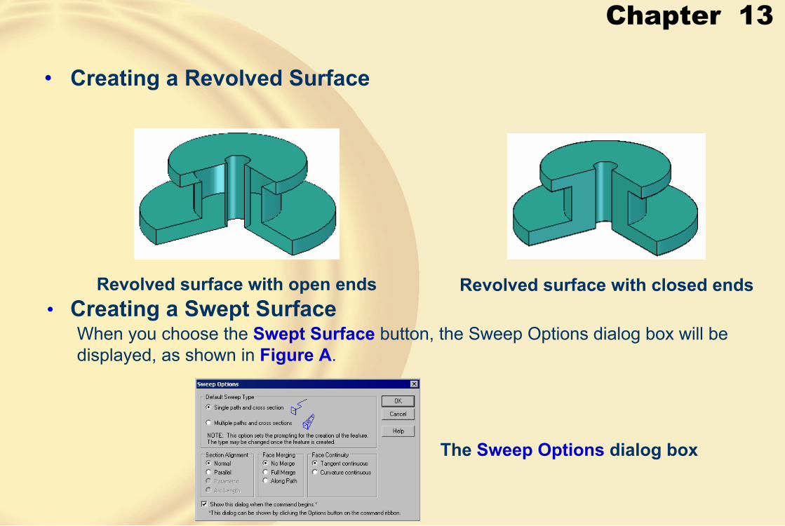
Chapter 13
• Creating a Revolved Surface
Revolved surface with open ends Revolved surface with closed ends• Creating a Swept Surface
The Sweep Options dialog box
When you choose the Swept Surface button, the Sweep Options dialog box will be displayed, as shown in Figure A.
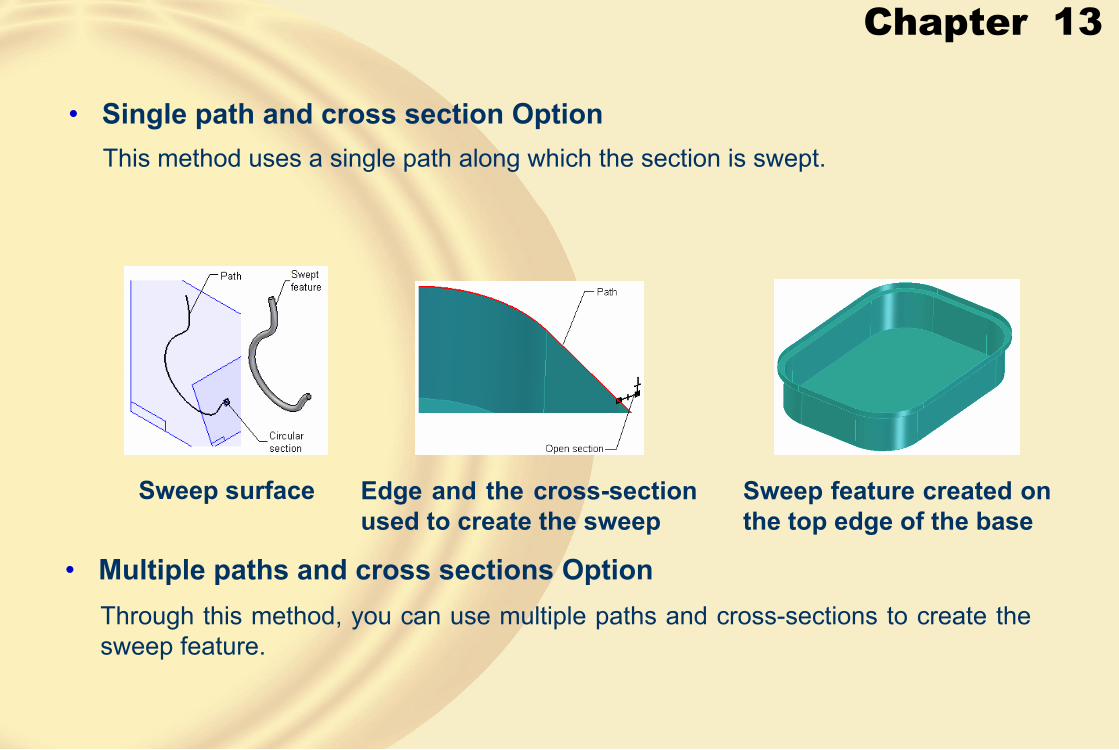
Chapter 13
• Single path and cross section OptionThis method uses a single path along which the section is swept.
Sweep surface Edge and the cross-section used to create the sweep
Sweep feature created on the top edge of the base
• Multiple paths and cross sections OptionThrough this method, you can use multiple paths and cross-sections to create the sweep feature.

Chapter 13
Paths and the cross section Resulting sweep feature
� CREATING SURFACES USING THE BLUESURF TOOLThe BlueSurf tool is a multipurpose tool of creating surfaces, such as complex loft surfaces with guide curves, surface patch, and so on.

Chapter 13
• Creating Surfaces by Joining Two Curves
Two curves Resulting surface
Two curves that are used as cross section and guide curve
Resulting surface
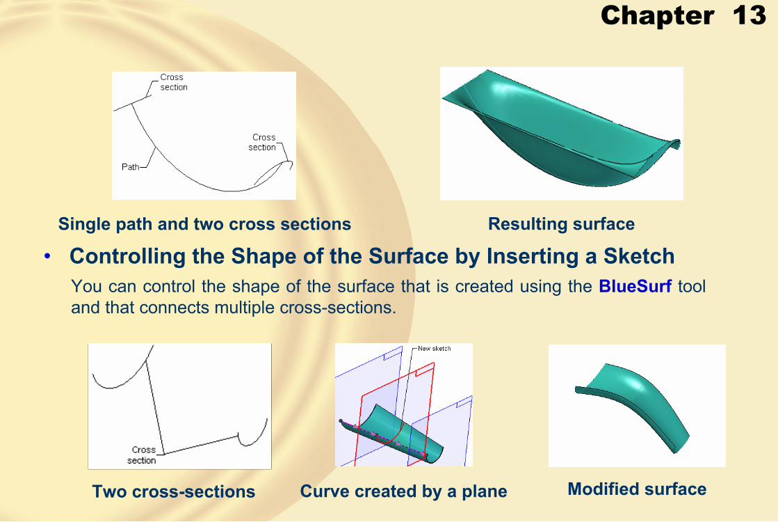
Chapter 13
Single path and two cross sections Resulting surface
• Controlling the Shape of the Surface by Inserting a SketchYou can control the shape of the surface that is created using the BlueSurf tool and that connects multiple cross-sections.
Two cross-sections Curve created by a plane Modified surface

Chapter 13
• Closing the EndsThe BlueSurf tool is also used to close the ends of a surface.
Edges of the surface Surface created by joining the edges
• Controlling the Connection Between the Two SurfacesThe BlueSurf tool is used to connect or join two sets of edges formed either by solid or surface features.

Chapter 13
Blue Surface Surface after manipulation
There are several end conditions that are provided in the BlueSurf Optionsdialog box, which is invoked by choosing the BlueSurf Options button from the ribbon bar.
The Standard tab of the BlueSurf Options dialog box
Chapter 13
• Tangency Control areaThis area consists of options that are used to specify the boundary conditions for the two end sections.
• Start section
The options in this drop-down list are :
• Natural.
• Parallel to section.• Normal to section.
• Tangent continuous.
• Tangent Interior.
• End sectionThe options in this list are used to determine the end conditions of the surface with respect to the adjacent surface.
Chapter 13
• Edge guide 1The options in this drop-down list are available only when a guide curve is used to create the surface.
• Edge guide 2The options in this drop-down list are available only when a guide curve is used to create the surface.
• End Capping AreaThe options in this area are available only when the sections are closed.
• Extent Type AreaThis area is available when there are at least three cross-sections.
• Curve ConnectivityThe options in this area are used to specify the type of connection between the guide curve and the cross-section.The options available are:
• Use Pierce Points
• Use BlueDots

Chapter 13
� CREATING SURFACES USING THE BOUNDED SURFACE TOOL
This tool is used to create a surface using one or more edges forming a closed loop.
Closed curve Surface created using the curves
Edge selected as a closed loop

Chapter 13
Bounded surface created by turning off the Face Tangency option
Bounded surface created using the Face Tangency option
� STITCHING MULTIPLE SURFACES TO CREATE A SINGLE SURFACE
The Stitched Surface tool is used to join multiple individual surfaces to create a single surface.
The Stitched Surface Options dialog box
Chapter 13
� CREATING OFFSET SURFACESThe Offset Surface tool allows you to offset the selected surface by a specified distance.
Offset surface
� COPYING A SURFACEThe Copy Surface tool is used to copy a face of a solid or surface feature.
Ribbon bar for the Copy Surface tool
Chapter 13
• Remove Internal BoundariesThis button allows you to remove internal boundaries from the surface and create a surface by ignoring them.
• Remove External BoundariesThis button allows you to remove external boundaries from the surface and create a surface by ignoring them.
Irregular boundary surface Surface created after joining the two curves

Chapter 13
� CREATING A BLUEDOTThe BlueDot tool is provided by Solid Edge to help you connect two curves.
Table specifying the keypoints of the entities that can be used to create the BlueDot
BlueDot on splines Surface created after joining the two curves using the BlueDot
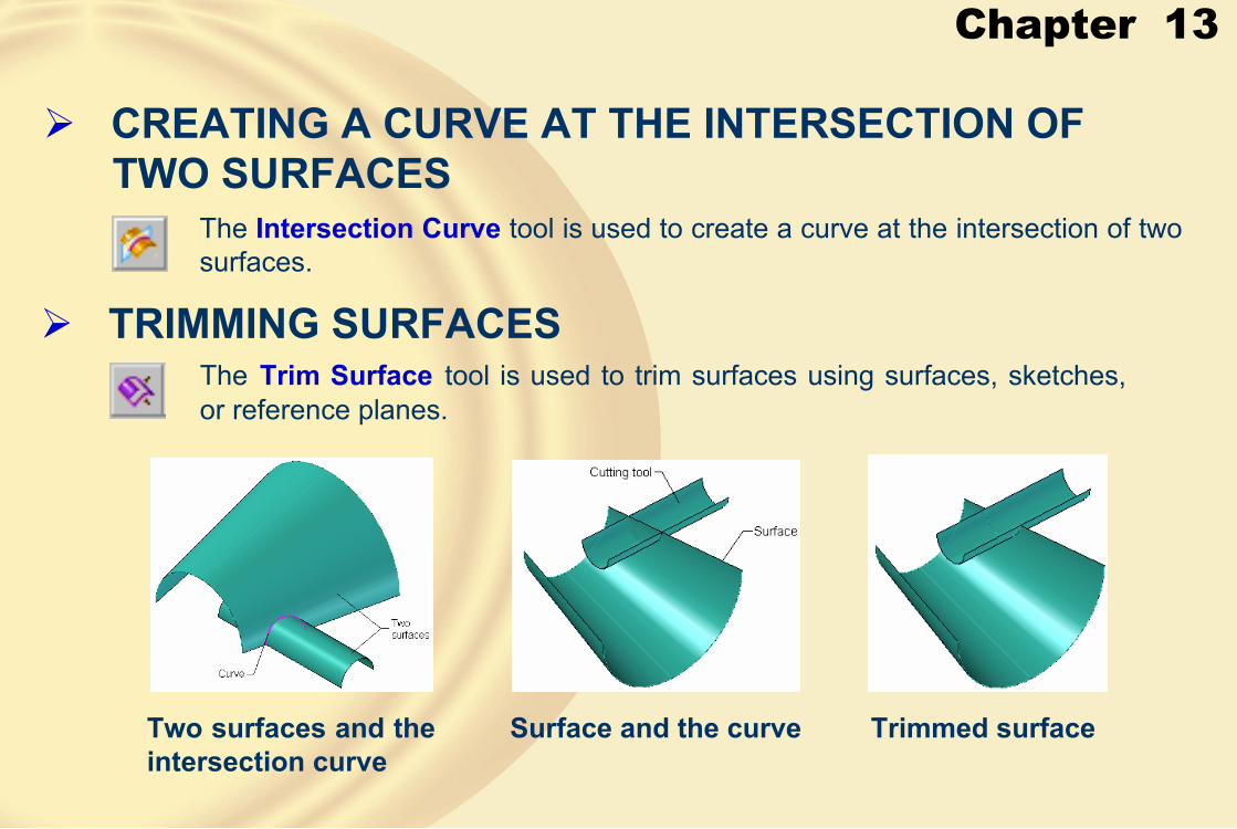
Chapter 13
� CREATING A CURVE AT THE INTERSECTION OF TWO SURFACES
The Intersection Curve tool is used to create a curve at the intersection of two surfaces.
� TRIMMING SURFACESThe Trim Surface tool is used to trim surfaces using surfaces, sketches, or reference planes.
Two surfaces and the intersection curve
Surface and the curve Trimmed surface
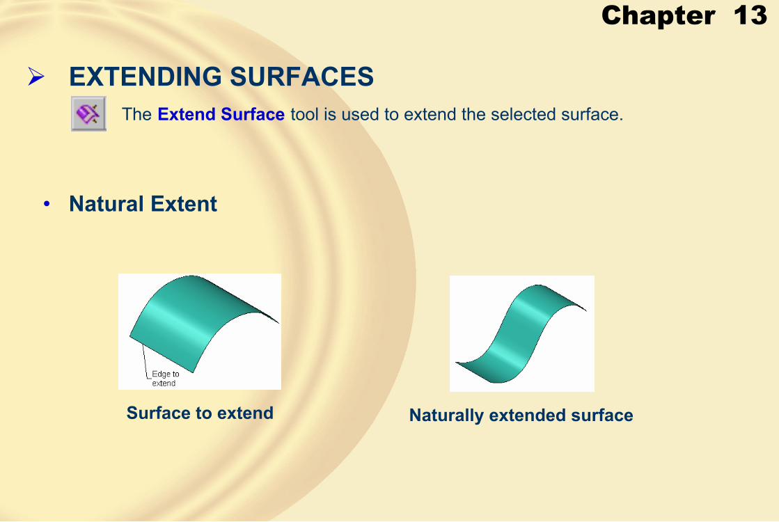
Chapter 13
� EXTENDING SURFACESThe Extend Surface tool is used to extend the selected surface.
• Natural Extent
Surface to extend Naturally extended surface

Chapter 13
• Linear ExtentThis button is available on the ribbon bar only when the surface selected to extend is created using a spline.
Surface to extend Surface after extending
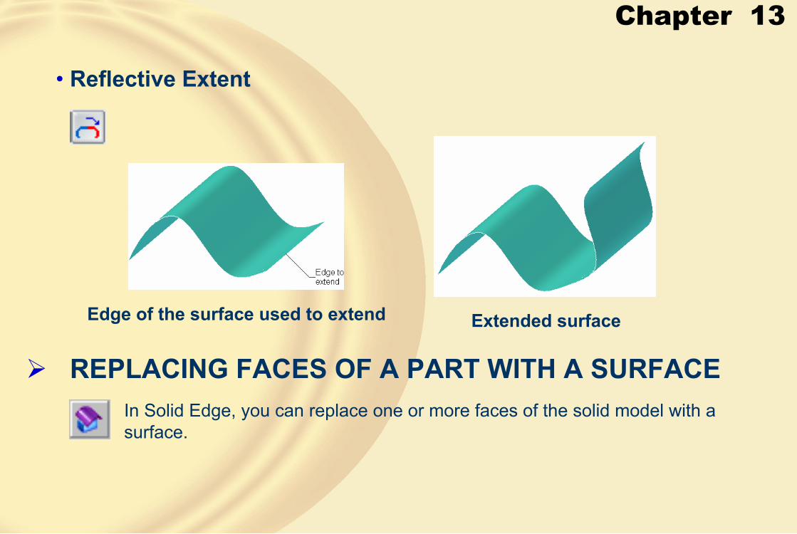
Chapter 13
� REPLACING FACES OF A PART WITH A SURFACEIn Solid Edge, you can replace one or more faces of the solid model with a surface.
• Reflective Extent
Edge of the surface used to extend Extended surface
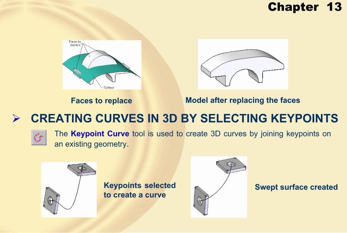
Chapter 13
Faces to replace Model after replacing the faces
� CREATING CURVES IN 3D BY SELECTING KEYPOINTSThe Keypoint Curve tool is used to create 3D curves by joining keypoints on an existing geometry.
Keypoints selected to create a curve
Swept surface created

Chapter 13
• Select Points StepThis button is chosen by default when you invoke the Keypoint Curve tool.
• Keypoints• Relative/Absolute Position• Redefine Point
• End Conditions StepThis button is chosen after you accept the selection of points to create a curve.
• Open• Closed

Chapter 13
• Start and End drop-down listsThese drop-down lists contain the options to set the end conditions of the curve.
� CREATING CURVES BY TABLE
The Insert Object dialog box
When you choose the Curve by Table button from the Surfacing toolbar, the Insert Object dialog box will be displayed.

Chapter 13
� PROJECTING CURVES ON SURFACESThe Project Curve tool is used to project curves on planar or nonplanar surfaces.
• Along VectorThis option projects the curve in the direction of a vector that defines the normal of the plane on which the curve is sketched.
Top view of projected curve Projecting a curve

Chapter 13
• Normal to Selected Surface OptionThis option projects the curve normal to the receiving surface.
Top view of the projected curve Projecting a curve
� CREATING A CURVE AT THE INTERSECTION OF TWO CURVES
The Cross Curve tool is used to create a 3D curve at the intersection of two 2D curves.

Chapter 13
Curve projected at the intersection of two curves
� DRAWING A CURVE ON A SURFACEThe Contour Curve tool is used to draw a curve on the selected face.
Curve created on the surface
Surface trimmed using the curve

Chapter 13
� DERIVING CURVESThe Derived Curve tool is used to derive a curve from the existing edge of a surface, of a solid, or from an existing sketch.
Edges selected to derive curve
Sweep created using the derived curve
� SPLITTING A CURVEThe Split Curve tool is used to split a curve using an intersecting entity, such as a reference plane, a Keypoint, a curve, and so on.

Chapter 13
� SPLITTING A BODYTo split a body, choose the Divide Part button from the Surfacing toolbar; you will be prompted to select a surface or a plane to divide the part. After you select a surface or a plane, a red arrow will be displayed and you will be prompted to click on the side to be divided into the new file. After you select the direction, choose the Finish button to display the Divide Part dialog box, as shown in Figure A.
Figure A The Divide Partdialog box
Solid body and the surface
Punch and die obtained after splitting the body
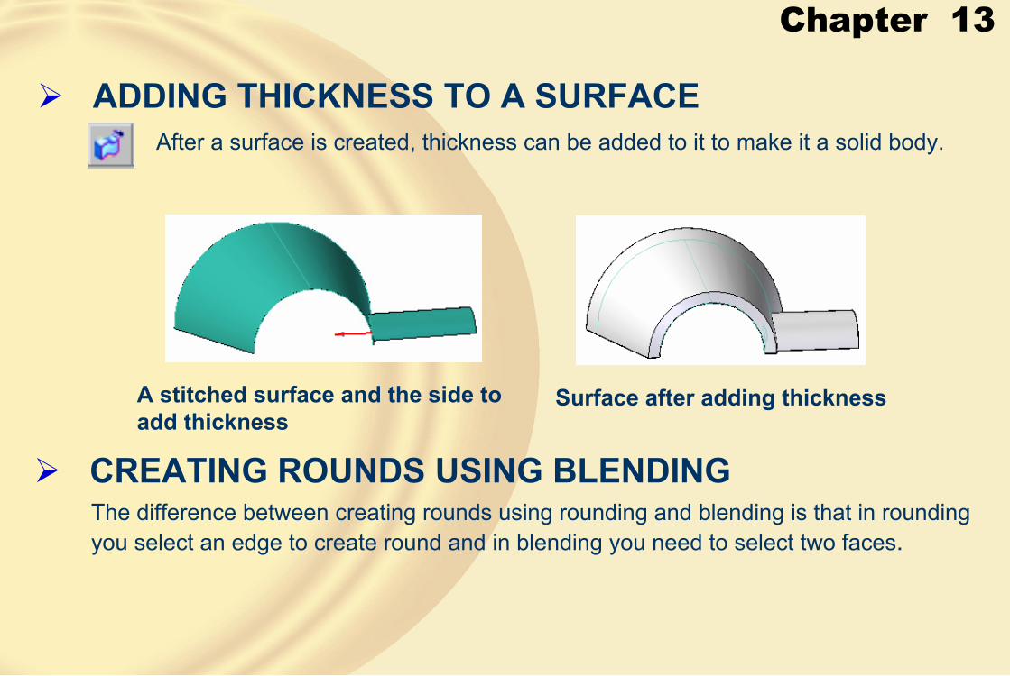
Chapter 13
� ADDING THICKNESS TO A SURFACEAfter a surface is created, thickness can be added to it to make it a solid body.
A stitched surface and the side to add thickness
Surface after adding thickness
� CREATING ROUNDS USING BLENDINGThe difference between creating rounds using rounding and blending is that in rounding you select an edge to create round and in blending you need to select two faces.
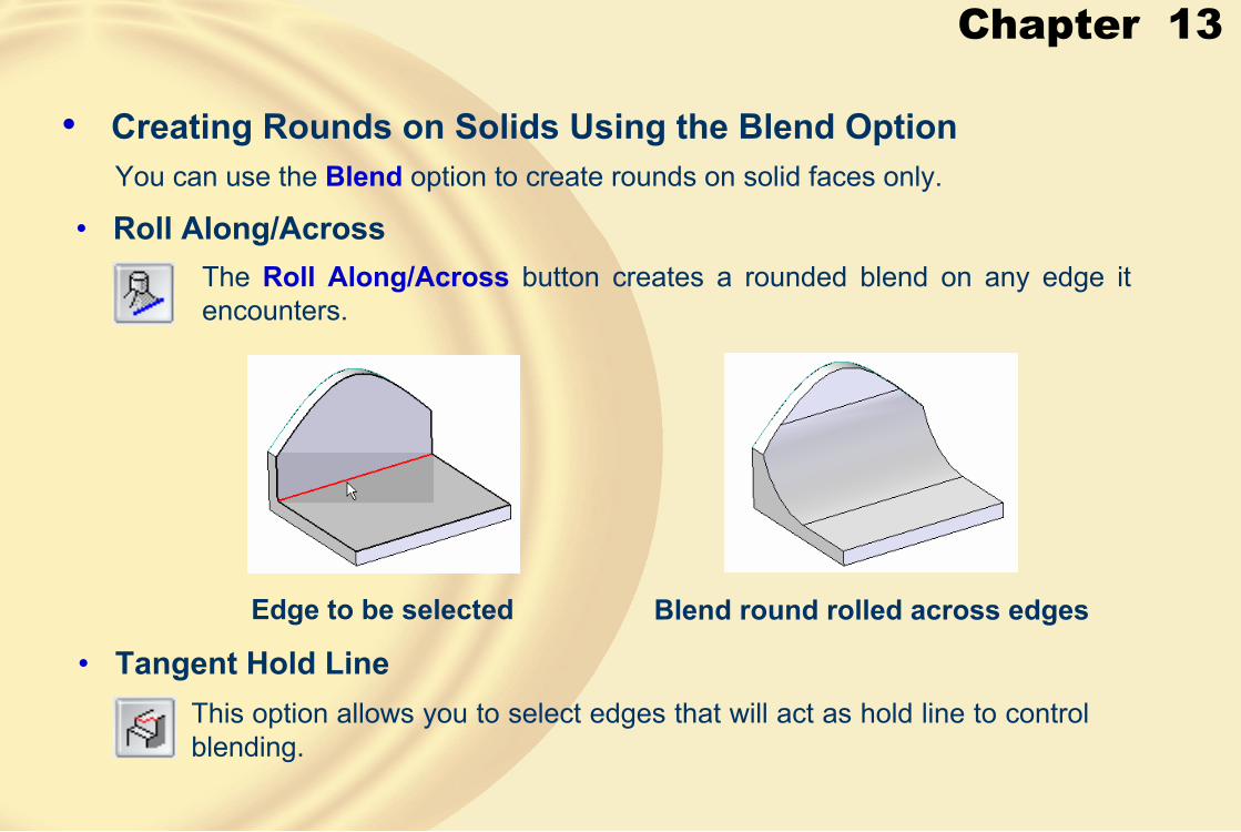
Chapter 13
• Creating Rounds on Solids Using the Blend OptionYou can use the Blend option to create rounds on solid faces only.
• Roll Along/AcrossThe Roll Along/Across button creates a rounded blend on any edge it encounters.
Edge to be selected Blend round rolled across edges
• Tangent Hold LineThis option allows you to select edges that will act as hold line to control blending.
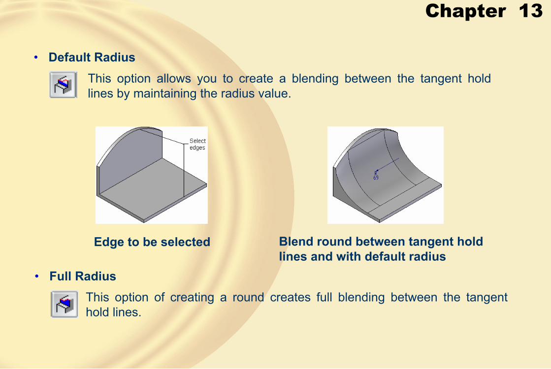
Chapter 13
• Default Radius
Edge to be selected Blend round between tangent hold lines and with default radius
• Full Radius
This option allows you to create a blending between the tangent hold lines by maintaining the radius value.
This option of creating a round creates full blending between the tangent hold lines.
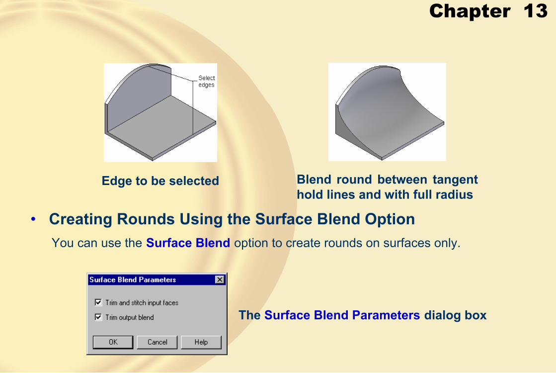
Chapter 13
Edge to be selected Blend round between tangent hold lines and with full radius
• Creating Rounds Using the Surface Blend OptionYou can use the Surface Blend option to create rounds on surfaces only.
The Surface Blend Parameters dialog box
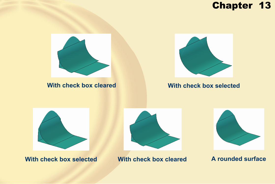
Chapter 13
With check box cleared With check box selected
With check box selected With check box cleared A rounded surface
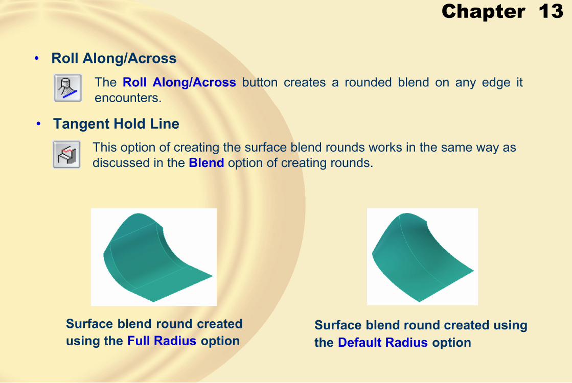
Chapter 13
• Tangent Hold Line
• Roll Along/AcrossThe Roll Along/Across button creates a rounded blend on any edge it encounters.
This option of creating the surface blend rounds works in the same way as discussed in the Blend option of creating rounds.
Surface blend round created using the Full Radius option
Surface blend round created using the Default Radius option

Chapter 13
• Specifying the Blend ShapeYou can specify the shape of the blended rounds before creating them using the options available in the Shape drop-down list.
Selecting the blend shape from the Shape drop-down list
• Constant Radius• Constant width• Chamfer• Bevel• Conic• Curvature continuous
Surface blend created using the Bevel option
Surface blend created using the Chamfer option

Chapter 13
� ADDING A DRAFT• From Parting Surface
This option allows you to select a parting geometry that acts as a pivot location about which the draft is added to the faces.
Construction surface Draft added to the faces
• Split DraftThe Split Draft option available in the Draft Options dialog box is used to split the selected face into two faces using the split surface so that different draft angles can be applied to both faces.

Chapter 13
Construction surface Draft added to the faces
• From Parting LineThis option allows you to select a construction curve that acts as a pivot location about which the draft is added to the faces.
Curve and the face selected to add draft
Draft added to the faces

Chapter 13
• Split DraftThe Split Draft option allows you to specify two different draft angles on selected faces.
• Step DraftThe Step Draft option will be available in the Draft Options dialog box when you select the From parting line radio button.
Draft added to the faces using thePerpendicular step faces option
Parting line, neutral plane, and the face selected to add a draft

Chapter 13
Draft added to the faces using the Taper step faces option
Draft added using the split line
� USING THE PARTING SPLIT TOOLThe Parting Split tool allows you to split the selected faces along a silhouette edge.
Reference plane selected
Parting edge created

Chapter 13
� USING THE PARTING SURFACE TOOLThe parting surface is used for creating molds, core, and cavity.
Parting surface created using the parting edge
Parting surface created using the edge chain
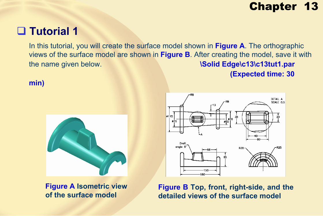
Chapter 13
� Tutorial 1In this tutorial, you will create the surface model shown in Figure A. The orthographic views of the surface model are shown in Figure B. After creating the model, save it with the name given below. \Solid Edge\c13\c13tut1.par
(Expected time: 30 min)
Figure A Isometric view of the surface model
Figure B Top, front, right-side, and the detailed views of the surface model

Chapter 13
1. Create the Base Feature.
Sketch of the base feature Revolved surface
2. Create the Second Feature.
Sketch with dimensions Extruded surface with draft

Chapter 13
3. Trim the Extruded Surface.
The trimmed bottom surface
4. Stitch the Two Surfaces.
5. Create Round.
6. Save the model.
Final surface model

Chapter 13
� Tutorial 2In this tutorial you will create the surface model shown in Figure A. The orthographic views of the surface model are shown in Figure B. After creating the model save it with the name given below. \Solid Edge\c13\c13tut2.par
(Expected time: 45 min)
Figure B Top, front, right-side, and the isometric views of the surface model
Figure A Surface model

Chapter 13
1. Create the Base Feature
2. Create the BlueSurface by Joining Two Sketches
Sketch with dimensions Extrude surface
Two sketches BlueSurface Mirror copy

Chapter 13
3. Create the BlueSurface at the End of Extruded Surface
4. Create the Cut on the BlueSurface
BlueSurface
Surfaces used for trimming Cylindrical surface from the top view
Trimmed BlueSurface

Chapter 13
5. Create the Cut on the Left Side of the BlueSurface
6. Trim the Extruded Surface
Surface after mirroring Trimmed surface
Extrude surfaces after trimming

Chapter 13
7. Stitch the Surfaces
8. Create Round
9. Choose the Save button to save the model
Round of radius 4 Edges to be selected
Final model

Chapter 13
� Exercise 1Create the surface model shown in Figure A. The orthographic views with dimensions are shown in Figure B. After creating the model save it with the name given below.
Solid Edge\c13\c13exr2.par (Expected time: 30 min)
Figure A Surface model Figure B Top and front views

Chapter 13
� Exercise 2Create the surface model shown in Figure A. The orthographic views and the isometric view are shown in the figure. After creating the model save it with the name given below.
Solid Edge\c13\c13exr1.par (Expected time: 30 min)
Figure A Top, front, right-side, and the isometric views of the surface model

Chapter 14
Learning Objectives:• Set the parameters for creating the sheet metal parts.
• Create the base of the sheet metal part.
• Add various types of flanges to the sheet metal part.
• Add a jog to the sheet metal part.
• Bend or unbend a part of the sheet metal part.
• Add corner bends to the sheet metal parts.
• Create dimples, louvers, drawn cutouts, and beads in the sheet metal component.
• Convert solid parts to sheet metal components.
• Create the flat pattern of the sheet metal parts.
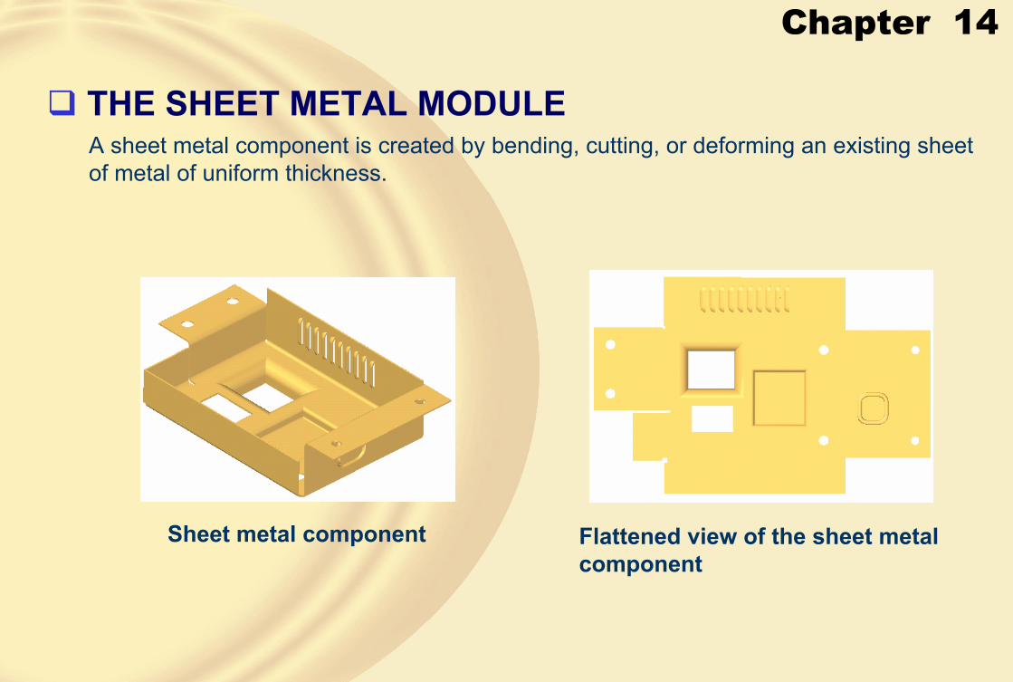
Chapter 14
A sheet metal component is created by bending, cutting, or deforming an existing sheet of metal of uniform thickness.
� THE SHEET METAL MODULE
Sheet metal component Flattened view of the sheet metal component

Chapter 14
Starting a new sheet metal document
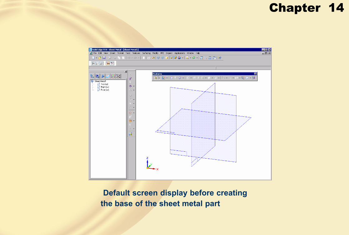
Chapter 14
Default screen display before creatingthe base of the sheet metal part

Chapter 14
• SETTING THE SHEET METAL PART PROPERTIES1. To set these options, choose Tools > Material Table from the menu bar; the Solid
Edge Material Table dialog box will be displayed with the Material tab active.
The Gage tab of the Solid Edge Material Table dialog box

Chapter 14
This edit box is used to set the default thickness for the sheet metal part. The thicknessspecified in this edit box will be displayed as the default thickness whenever you invoke a tool to create the sheet metal part.
� Material thickness
Sheet with 5mm bend radiusSheet with 1mm bend radius

Chapter 14
• Relief depthWhenever you bend a sheet metal component or create a flange such that the bend does not extend throughout the length of the edge, a groove is added at the end of the bend so that the walls of the sheet metal part do not intersect when folded or unfolded. This groove is known as relief.
Relief width = 1 Relief width = 5
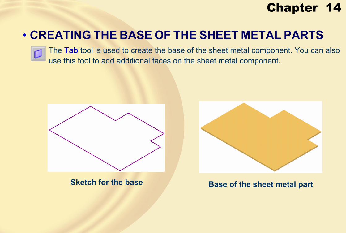
Chapter 14
• CREATING THE BASE OF THE SHEET METAL PARTSThe Tab tool is used to create the base of the sheet metal component. You can also use this tool to add additional faces on the sheet metal component.
Sketch for the base Base of the sheet metal part

Chapter 14
• ADDING FLANGES TO A SHEET METAL PARTSolid Edge allows you to directly add a folded face to the existing sheet metal part. This is done using the Flange tool.
The Flange Options dialog box
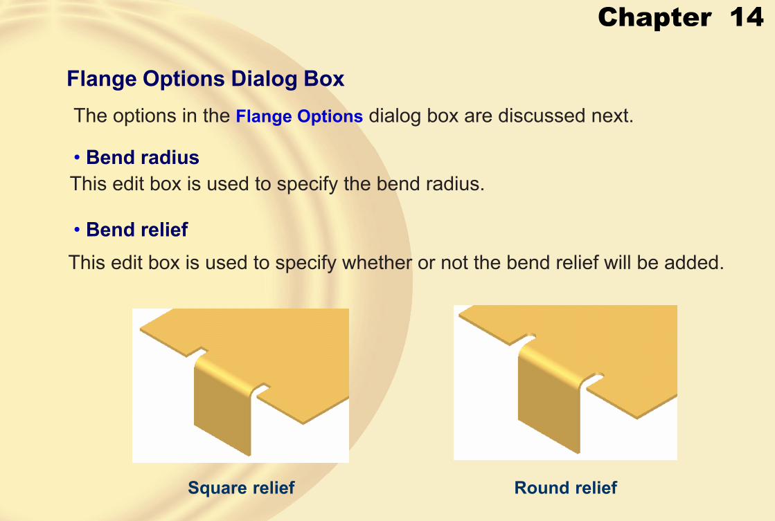
Chapter 14
Flange Options Dialog BoxThe options in the Flange Options dialog box are discussed next.
• Bend radiusThis edit box is used to specify the bend radius.
• Bend reliefThis edit box is used to specify whether or not the bend relief will be added.
Square relief Round relief

Chapter 14
• Corner relief
Flanges with no corner relief Flanges with bend only corner relief

Chapter 14
Flanges with bend and facecorner relief
Flanges with bend and face chain corner relief

Chapter 14
• Edge Step• Material Inside
• Material Outside
• Bend Outside
• Full Width
• Centered
• At End
• From Both Ends
• From End

Chapter 14
• DistanceThis edit box is used to specify the distance of the flange.
• Angle
• Profile Step
You can choose this button to modify the profile of the flange.
• Offset StepThis step is used when you want to add some offset between the flange and the edge selected to create it
• Inside Dimension
• Outside Dimension

Chapter 14
• CREATING CONTOUR FLANGESContour flanges are the ones that are created by using an open sketched shape.
• Extent StepThe options in this step are discussed next
• Finite Extent
Preview of the contour flange The resulting contour flange
This button is chosen to specify the extent of the contour flange using a distance value.
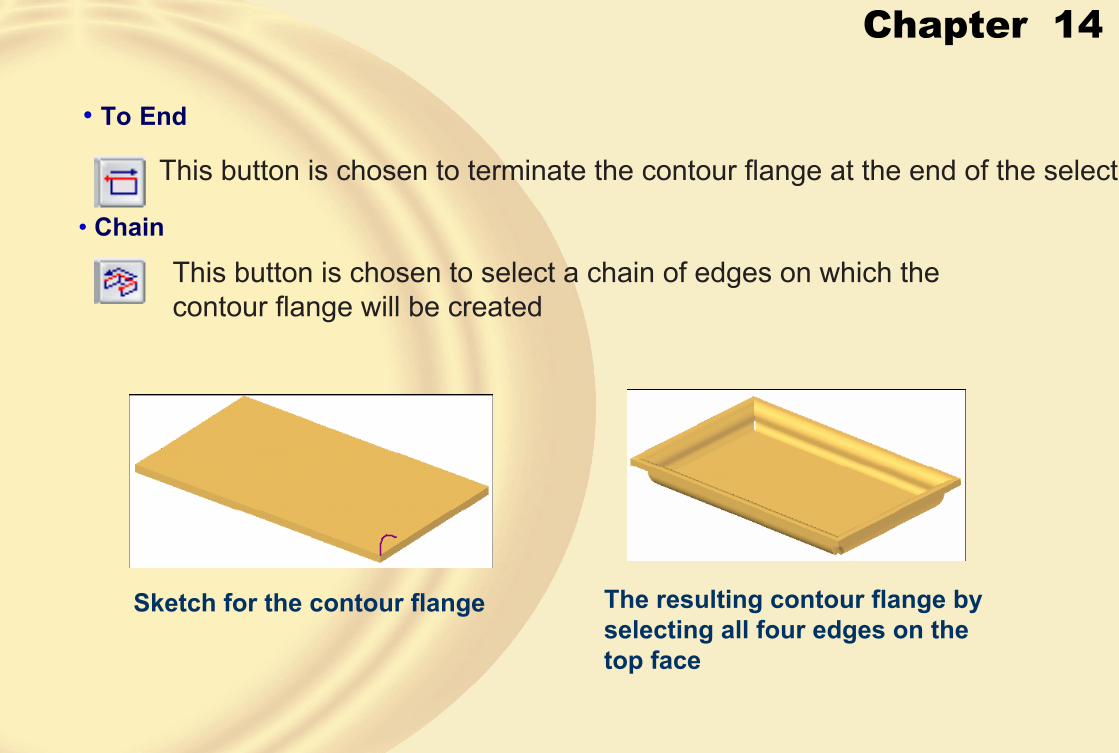
Chapter 14
• To End
This button is chosen to terminate the contour flange at the end of the selecte
• Chain
This button is chosen to select a chain of edges on which the contour flange will be created
Sketch for the contour flange The resulting contour flange by selecting all four edges on the top face

Chapter 14
• Modifying the Contour Flange OptionsYou can choose the Options button from the ribbon bar to modify the contour flange options.
The options in the Miters and Corners tab,are discussed next.
The Miters and Corners tab of the ContourFlange Options dialog box

Chapter 14
• Start End/Finish End AreasThe options in these areas are used to create a miter corner at the start end and the finish end of the contour flange.
• Angle
The Angle edit boxes in both the areas are used to specify the miter angle at the start and finish ends.
• Normal to thickness face
This radio button is used to create the miter normal to the thickness face.
Preview of the -45-degrees miter at the two ends Top view of the miter normal to
the thickness face

Chapter 14
Top view of the miter normal to the source face
Chapter 14
• Interior Corners Area
The options in this area are used to specify the corner treatment while creating the contour flange at multiple edges. The optionsavailable in this drop-down list are discussed next.• Open
• Close
• Circle cutout
• CREATING LOFTED FLANGESThe Lofted Flange tool is used to create a lofted flange between two selected profiles.

Chapter 14
Sketches to be used to create the lofted flange
Preview of the resulting lofted flange

Chapter 14
• ADDING THE JOG TO THE SHEETThe Jog tool is used to add a jog to an existing sheet metal part using a sketched line segment.
Base sheet and the line to add Model after adding the jog

Chapter 14
• BENDING THE SHEET METAL PARTThe Bend tool is used to bend an existing sheet metal part using a sketched line segment
Base sheet and the line to bend the sheet
Model after adding the bend
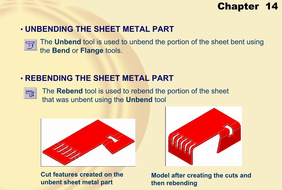
Chapter 14
• UNBENDING THE SHEET METAL PARTThe Unbend tool is used to unbend the portion of the sheet bent using the Bend or Flange tools.
• REBENDING THE SHEET METAL PARTThe Rebend tool is used to rebend the portion of the sheet that was unbent using the Unbend tool
Cut features created on the unbent sheet metal part
Model after creating the cuts and then rebending

Chapter 14
• FILLETING OR CHAMFERING CORNERS OF A SHEET METAL PART
The Break Corner tool is used to add fillets or chamfers to the selected corners of the sheet metal part
• TREATING 2 BEND CORNERS OF A SHEET METAL PARTThe Close 2-Bend Corner tool is used to treat the corner created by two be
Two bends selected for the open corner treatment
Model with the open corner treatment of the two bends

Chapter 14
Model with the open corner treatment with a gap of 2mm
Model with the circular cutout corner treatment of the two bends
Overlapping of walls in the corner treatment

Chapter 14
• CREATING DIMPLES IN A SHEET METAL PARTSolid Edge allows you to sketch a user-defined shape and use it to create a dimple in the sheet metal component.
The Dimple Options dialog box

Chapter 14
Dimple with no taper Dimple with a 25-degrees taper

Chapter 14
Dimple created in the forward direction with a 25-degrees taper
Dimple created with an open profile
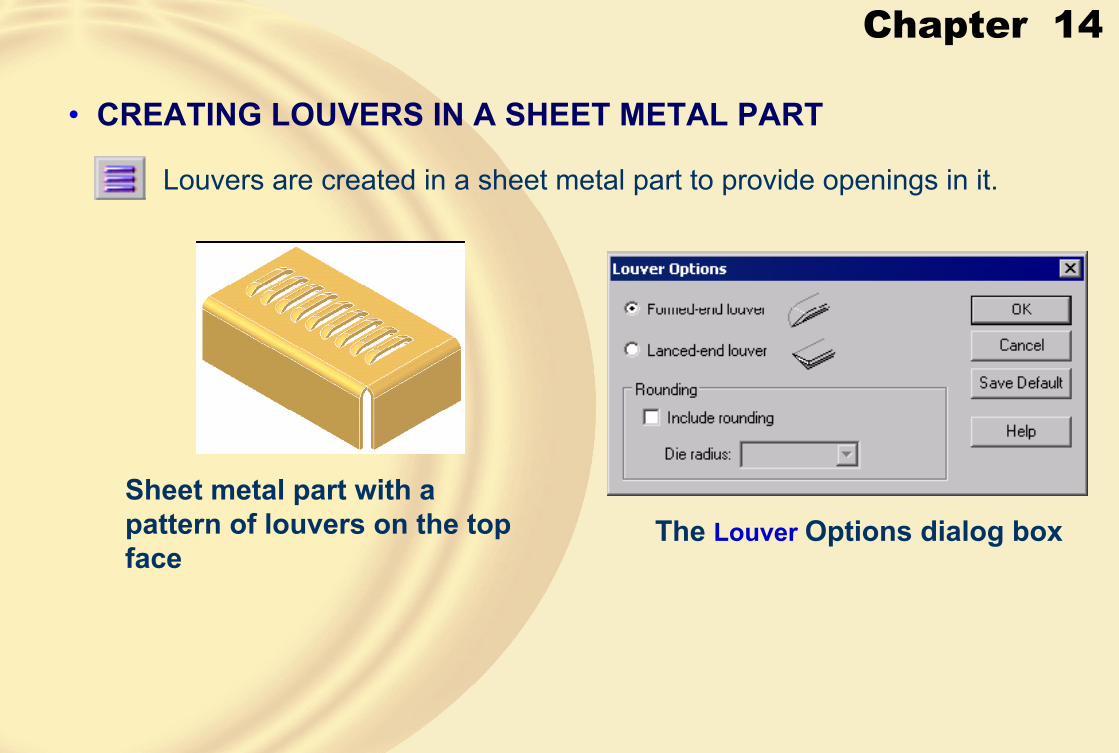
Chapter 14
• CREATING LOUVERS IN A SHEET METAL PART
Louvers are created in a sheet metal part to provide openings in it.
Sheet metal part with a pattern of louvers on the top face
The Louver Options dialog box

Chapter 14
Formed-end louvers Formed-end louvers
Preview of the louver

Chapter 14
• CREATING DRAWN CUTOUTS IN A SHEET METAL PARTThe drawn cutouts are exactly the same as the dimples, with the only difference being that for drawn cutouts, the end face is open.
Drawn cutouts of various shapes
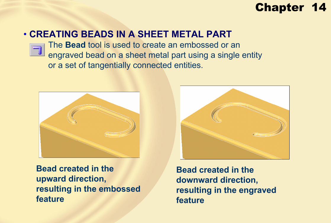
Chapter 14
• CREATING BEADS IN A SHEET METAL PARTThe Bead tool is used to create an embossed or an engraved bead on a sheet metal part using a single entity or a set of tangentially connected entities.
Bead created in the upward direction, resulting in the embossed feature
Bead created in the downward direction, resulting in the engraved feature
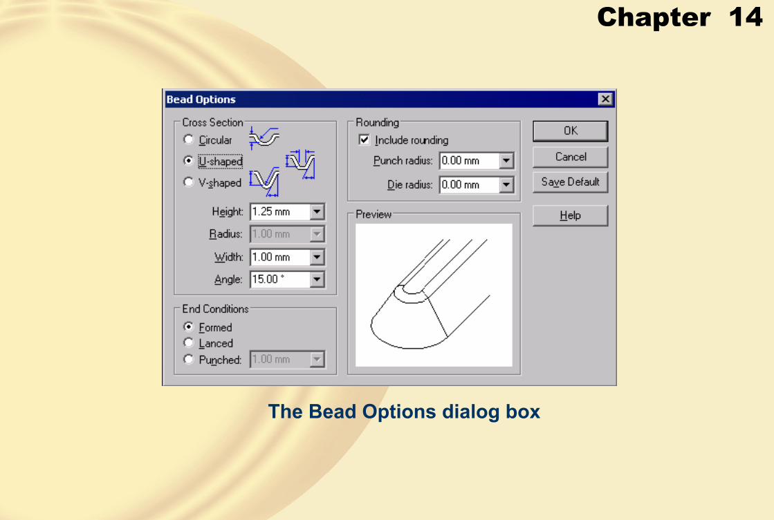
Chapter 14
The Bead Options dialog box

Chapter 14
Circular cross-section bead U-shaped bead V-shaped bead
Formed end condition Lanced end condition
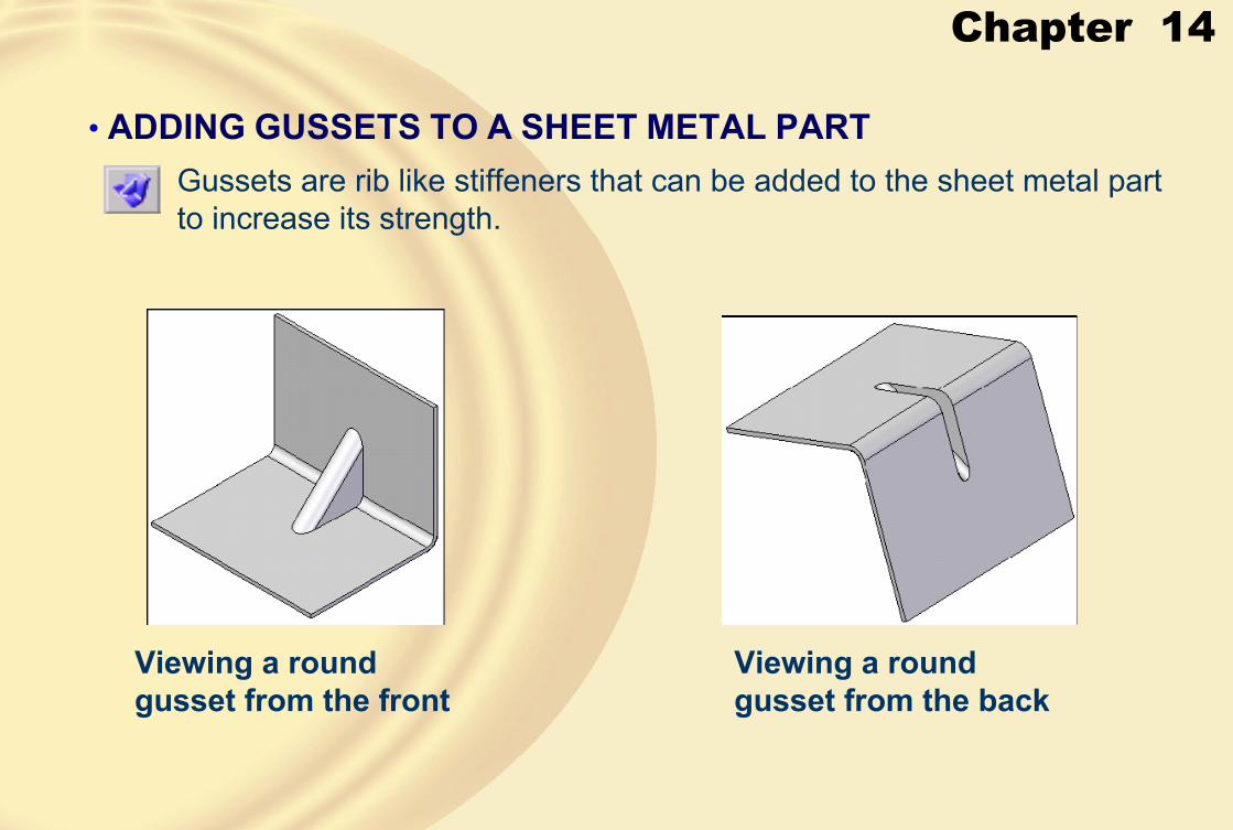
Chapter 14
• ADDING GUSSETS TO A SHEET METAL PARTGussets are rib like stiffeners that can be added to the sheet metal part to increase its strength.
Viewing a round gusset from the front
Viewing a round gusset from the back

Chapter 14
A user-defined gussetA square gusset

Chapter 14
The Gusset Options dialog box

Chapter 14
A round gusset A square gusset
A gusset with a taper angle of 25-degrees
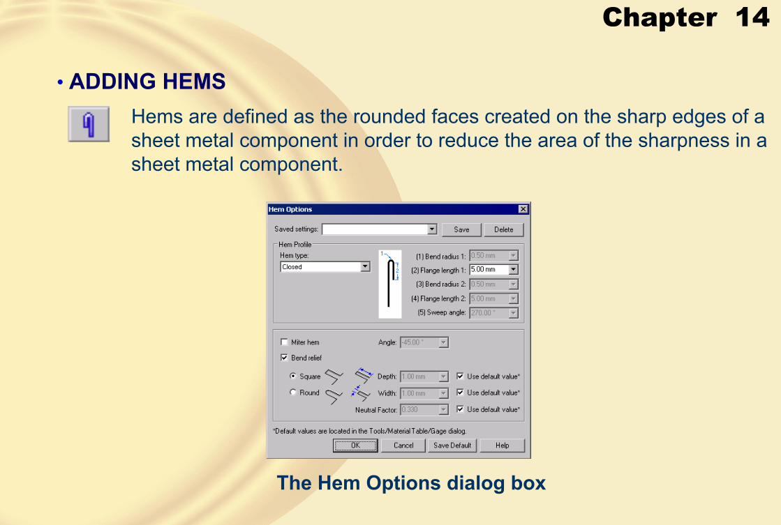
Chapter 14
• ADDING HEMSHems are defined as the rounded faces created on the sharp edges of a sheet metal component in order to reduce the area of the sharpness in a sheet metal component.
The Hem Options dialog box
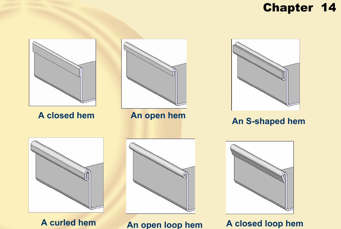
Chapter 14
A closed hem An open hem An S-shaped hem
A curled hem An open loop hem A closed loop hem

Chapter 14
A centered loop hem
An open hem with a negative miter
An open hem with a positive miter

Chapter 14
• CONVERTING A SOLID PART TO A SHEET METAL PART
Solid Edge allows you to convert a solid part to a sheet metal part.
Shelled box to be converted into a sheet metal part
After converting to the sheet metal part
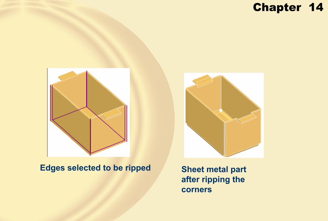
Chapter 14
Edges selected to be ripped Sheet metal part after ripping the corners
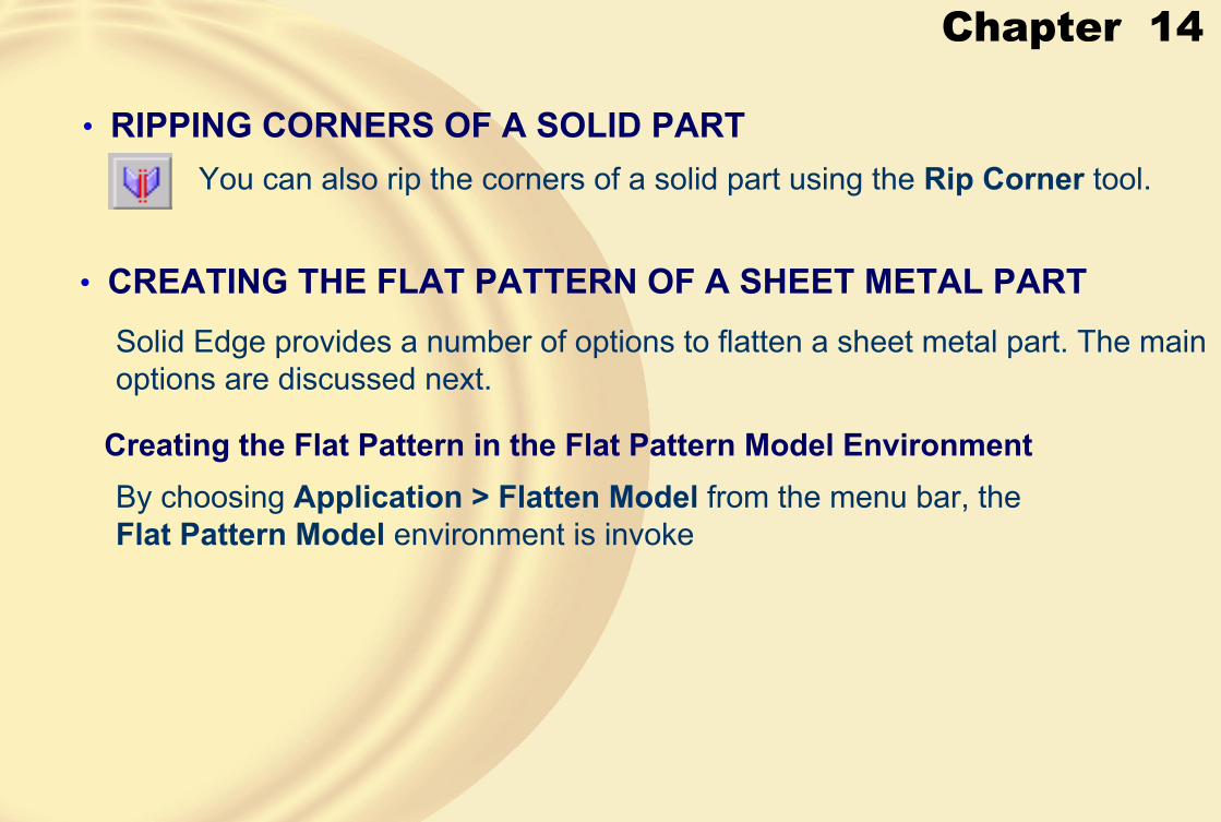
Chapter 14
• RIPPING CORNERS OF A SOLID PARTYou can also rip the corners of a solid part using the Rip Corner tool.
• CREATING THE FLAT PATTERN OF A SHEET METAL PARTSolid Edge provides a number of options to flatten a sheet metal part. The main options are discussed next.
Creating the Flat Pattern in the Flat Pattern Model EnvironmentBy choosing Application > Flatten Model from the menu bar, the Flat Pattern Model environment is invoke
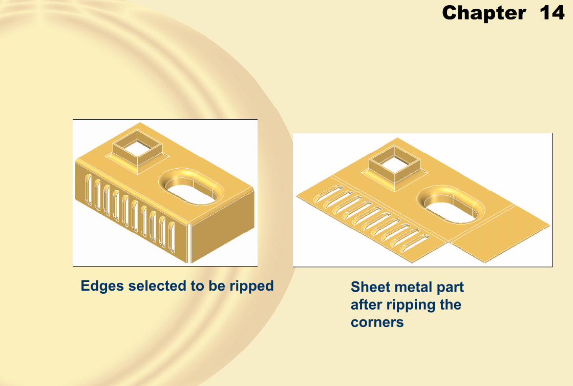
Chapter 14
Edges selected to be ripped Sheet metal part after ripping the corners
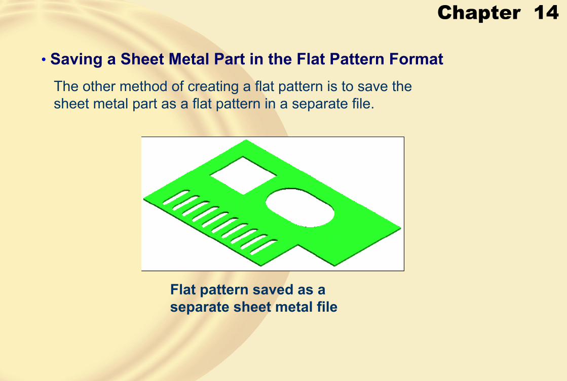
Chapter 14
• Saving a Sheet Metal Part in the Flat Pattern FormatThe other method of creating a flat pattern is to save the sheet metal part as a flat pattern in a separate file.
Flat pattern saved as a separate sheet metal file

Chapter 14
• TUTORIAL1In this tutorial, you will create the sheet metal part of the Holder Clip shown in Figure A. The flat pattern of the component is shown in Figure B. Assume the missing dimensions of the part. The material thickness, bend radius, relief depth, and relief width is 1mm. After creating the sheet metal component, create its flat pattern. Save the component with the name given below. \Solid Edge\c14\c14tut1.psm
(Expected time: 45 min)
Figure A Sheet metal part for Tutorial 1
Figure B Flat pattern of the sheet metal part for Tutorial 1

Chapter 14
• Starting a New Sheet Metal File• Creating the Top Face
Sketch for the top face of the part Top face of the part

Chapter 14
• Creating the Flanges
Preview of the first flange Preview of the second flange
Preview of the centered flange Preview of the fourth flange

Chapter 14
Preview of the fifth flange Preview of the sixth flange• Creating Louvers on the Top Face
Profile of the louver Louver created on the top face

Chapter 14
• Creating Holes
Sheet metal part after creating the five holes

Chapter 14
• Creating the Drawn Cutout on the Right Face of the Model
Profile of the drawn cutout The final sheet metal part

Chapter 14
• Generating the Flat Pattern
Flat pattern of the sheet metal part

Chapter 14
In this tutorial, you will create the sheet metal component shown in Figure 14-108. The flat pattern of the component is shown in Figure 14-109. The dimensions of the model are shown in Figure 14-110. The material thickness, bend radius, relief depth, and relief width is 1mm.Assume the missing dimensions. Save the model with the name given below. \Solid Edge\c14\c14tut2.psm (Expected time: 30 min)
• TUTORIAL 2
Sheet metal part for Tutorial 2 Flat pattern of the part
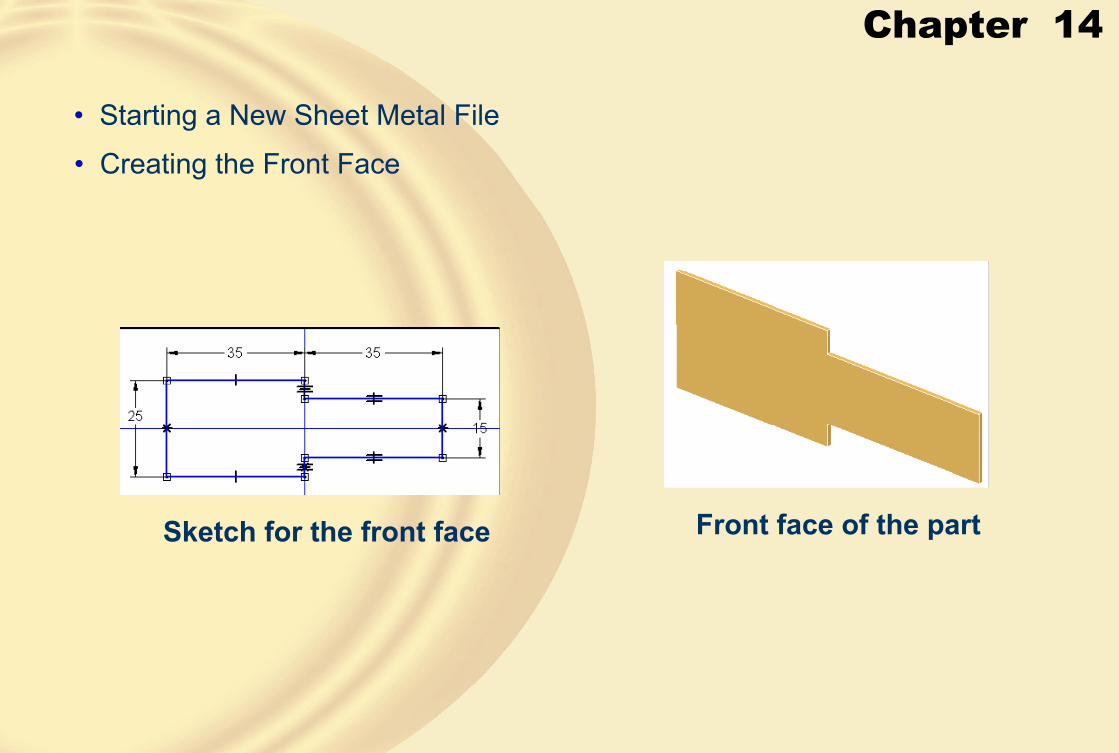
Chapter 14
• Starting a New Sheet Metal File
• Creating the Front Face
Sketch for the front face Front face of the part

Chapter 14
• Creating the Flanges
Preview of the first flange Preview of the second flange
Model after creating all the flanges

Chapter 14
• Closing the Corner between the First Two Flanges
Partial view of the part after closing the corner

Chapter 14
• Creating Holes
Final sheet metal part after creating the holes

Chapter 14
• Generating the Flat Pattern
Flat pattern of the sheet metal part.
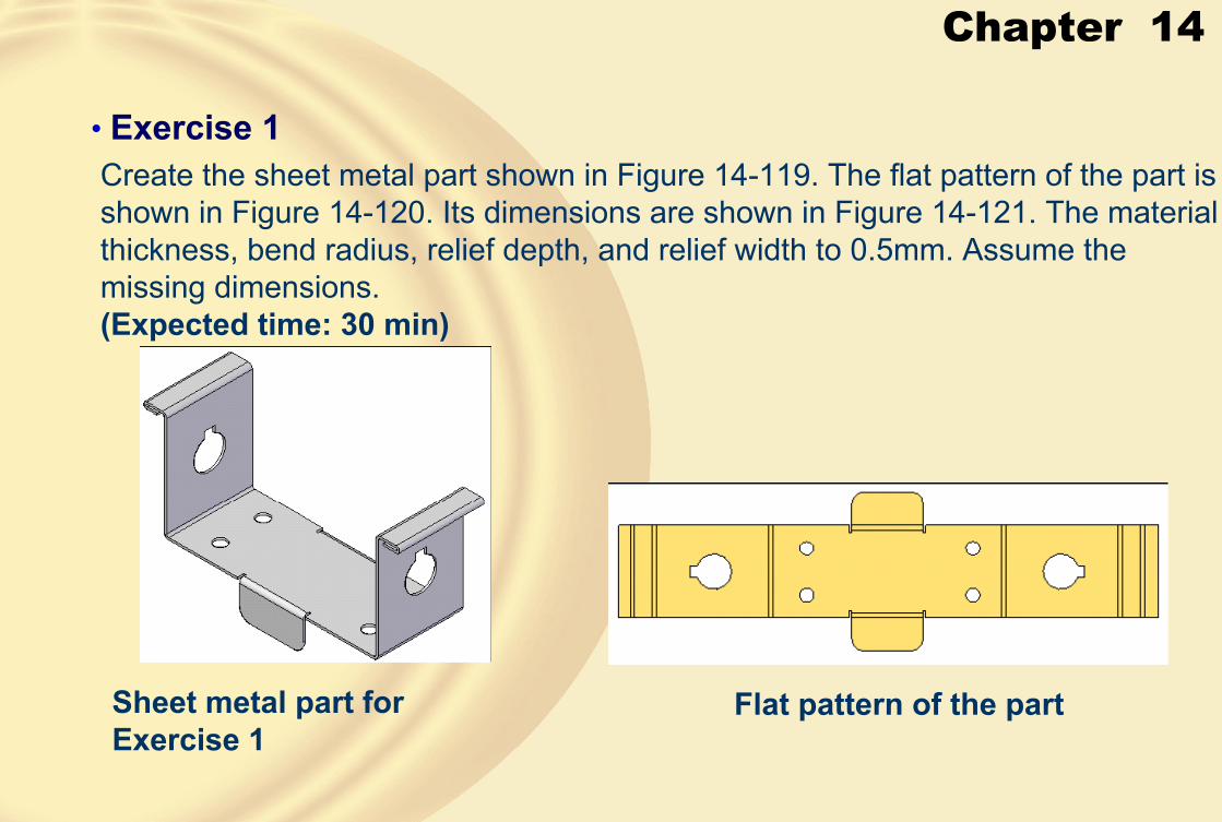
Chapter 14
• Exercise 1Create the sheet metal part shown in Figure 14-119. The flat pattern of the part is shown in Figure 14-120. Its dimensions are shown in Figure 14-121. The material thickness, bend radius, relief depth, and relief width to 0.5mm. Assume the missing dimensions.(Expected time: 30 min)
Sheet metal part for Exercise 1
Flat pattern of the part

Chapter 15
Learning Objectives:• Create components of the project assemblies in the Part environment of Solid Edge.
• Assemble the components of assemblies in the Assembly environment.
• Generate the drawing views of assemblies in the Draft environment.

Chapter 15
In this tutorial, you will create the components of the Motor Blower assembly shown in Figure 1. The exploded view of the assembly is shown in Figure 2. The details of the components of the Motor Blower assembly are shown in Figures 3 through 8. You will also generate the following drawing views of the assembly:
a. Top viewb. Front viewc. Left-side viewd. Isometric view
(Expected time: 3 hrs)
Figure 1 Motor Blower assembly
Figure 2 Exploded view of the assembly
� Tutorial 1

Chapter 15
Figure 3 Dimensions of the Upper Housing
Figure 4 Dimensions of the Lower Housing
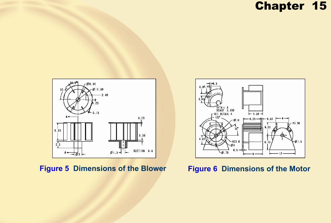
Chapter 15
Figure 5 Dimensions of the Blower Figure 6 Dimensions of the Motor

Chapter 15
Figure 7 Dimensions of the Blower Figure 8 Dimensions of the Motor

Chapter 15
1. Draw the profile of the base feature, as shown in Figure 9, and exit the sketching environment.
Figure 9 Sketch of the base feature2. Extrude the sketch symmetrically to both sides of the profile plane up to the depth of 8.
The isometric view of the base feature is shown in Figure 10.
Figure 10 Base feature
� Creating the Lower Housing

Chapter 15
3. Select the top face of the base feature and draw the sketch, as shown in Figure 11.
Figure 11 Sketch of a revolved cut
4. Create the revolved cut by entering the angle of revolution 180 in the Angleedit box; the cutout is created, as shown in Figure 12.
Figure 12 Model after creating the revolved cut

Chapter 15
5. Draw the sketch of the cutout feature as shown in Figure 13.
Figure 13 Sketch of a cutout feature
6. Create the cutout feature, as shown in Figure 14.
Figure 14 Model after creating the cutout

Chapter 15
7. Create another cutout on the back face of the base feature, as shown in Figure 15.
Figure 15 Model after creating the second cutout
8. Place the profile of the hole on the top face of the base feature and add the required dimensions, as shown in Figure 16.
Figure 16 Hole profile placed on the top face

Chapter 15
9. Final model, after creating the pattern, is shown in Figure 18.
Figure 18 Final model of the Lower Housing

Chapter 15
1. Draw the profile of the base feature, as shown in Figure 19, and then exit the sketching environment.
Figure 19 Sketch of the base feature
� Creating the Blower
2. Draw the profile of the base feature, as shown in Figure 20, and then exit the sketching environment.
Figure 20 Revolved feature

Chapter 15
3. Draw the profile of the base feature, as shown in Figure 21, and then exit the sketching environment.
Figure 21 Sketch with dimensions
4. Extrude the profile, as shown in Figure 22.
Figure 22 Protrusion feature

Chapter 15
5. Pattern the extruded feature as shown in Figure 23.
Figure 23 Model after creating the pattern
6. Select the face of the base feature shown in Figure 24 to place the hole.
Figure 24 Protrusion feature
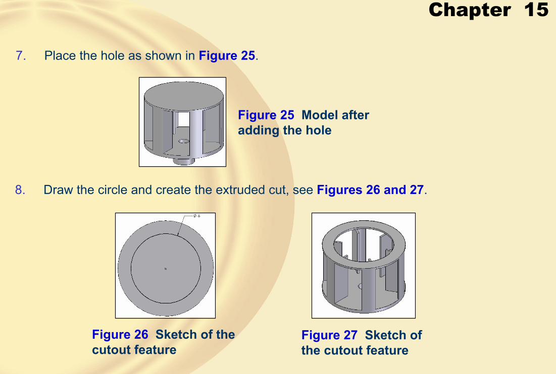
Chapter 15
7. Place the hole as shown in Figure 25.
Figure 25 Model after adding the hole
8. Draw the circle and create the extruded cut, see Figures 26 and 27.
Figure 26 Sketch of the cutout feature
Figure 27 Sketch of the cutout feature
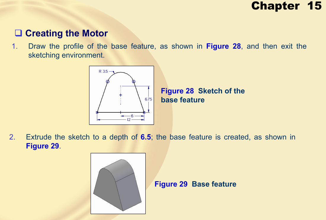
Chapter 15
1. Draw the profile of the base feature, as shown in Figure 28, and then exit the sketching environment.
Figure 28 Sketch of the base feature
� Creating the Motor
2. Extrude the sketch to a depth of 6.5; the base feature is created, as shown in Figure 29.
Figure 29 Base feature

Chapter 15
3. Draw the profile of the base feature, as shown in Figure 30 and exit the sketching environment.
Figure 30 Sketch with a constraint
4. Extrude the sketch to a depth of 2.25; the protrusion feature is created, as shown in Figure 31.
Figure 31 Isometric view of the model after creating the second feature

Chapter 15
5. Draw a circle, as shown in Figure 32, and modify its diameter to 10.
Figure 32 Sketch of the third feature
6. Extrude the sketch to a distance of 0.5; the third feature is created, as shown in Figure 33.
Figure 33 Protrusion feature

Chapter 15
7. Draw the profile of the protrusion feature, as shown in Figure 34.
Figure 34 Sketch with dimensions
8. Extrude the sketch to a distance of 8; the fourth feature is created, as shown in Figure 35.
Figure 35 Protrusion feature

Chapter 15
9. Draw the sketch, as shown in Figure 36.
Figure 36 Sketch of the cutout
10. Create the extruded cut, as shown in Figure 37.
Figure 37 Protrusion feature

Chapter 15
11. Patten the cut feature, see Figures 38 and 39.
Figure 38 Sketch for pattern Figure 39 Pattern created
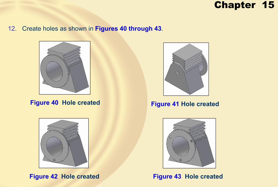
Chapter 15
12. Create holes as shown in Figures 40 through 43.
Figure 40 Hole created Figure 41 Hole created
Figure 42 Hole created Figure 43 Hole created
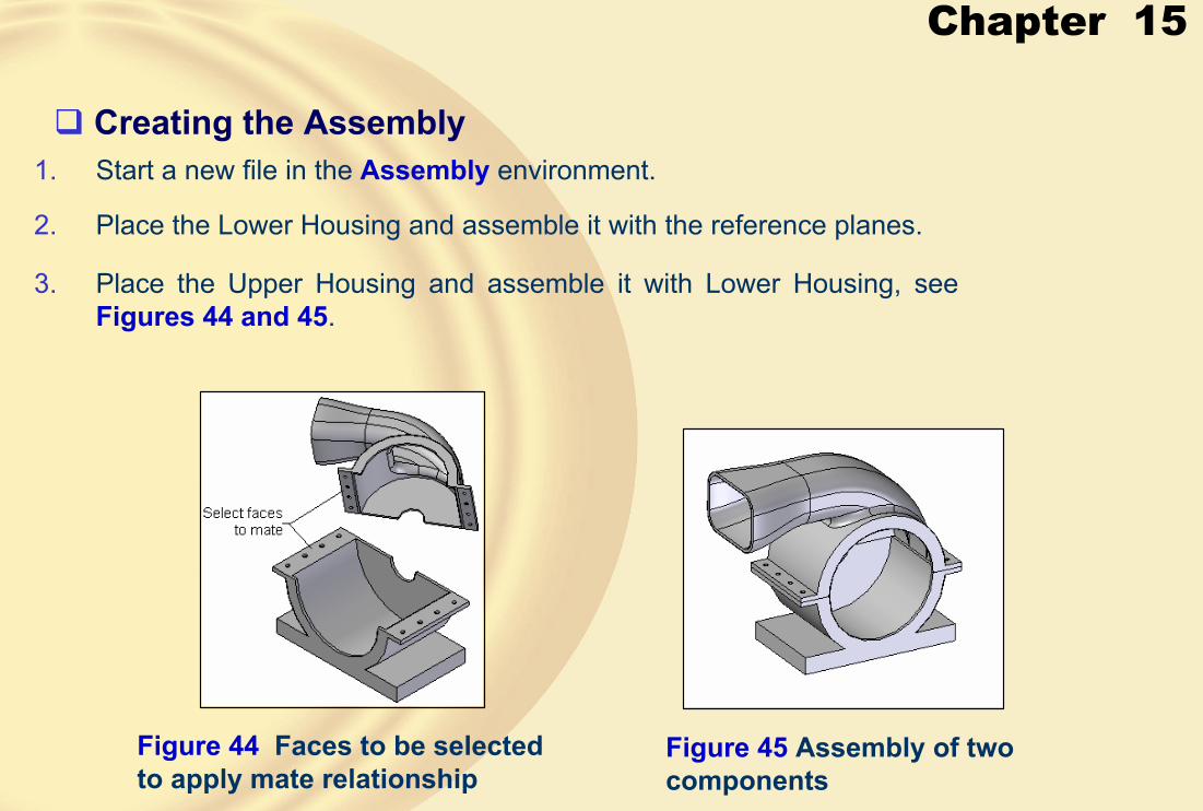
Chapter 15
1. Start a new file in the Assembly environment.� Creating the Assembly
Figure 44 Faces to be selected to apply mate relationship
2. Place the Lower Housing and assemble it with the reference planes.
3. Place the Upper Housing and assemble it with Lower Housing, see Figures 44 and 45.
Figure 45 Assembly of two components

Chapter 15
4. Assemble Motor with the Lower Housing and Upper Housing, see Figures 46 through 48.
Figure 46 Cylindrical faces to select
Figure 47 Faces to mate
Figure 48 Assembly of blower with the other components

Chapter 15
5. Assemble Shaft with the Blower, see Figure 49 through 51.
Figure 49 Faces to mate Figure 50 Shaft partially assembled
Figure 51 Assembly after assembling the Shaft
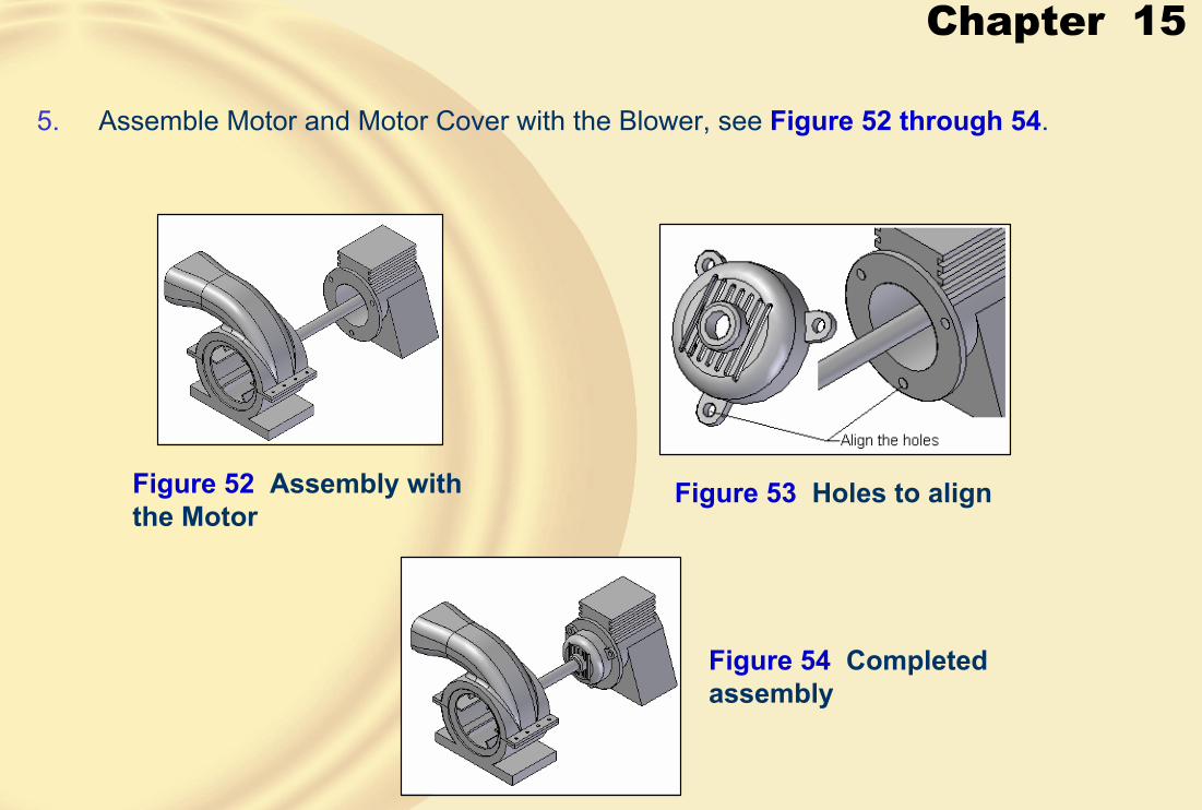
Chapter 15
5. Assemble Motor and Motor Cover with the Blower, see Figure 52 through 54.
Figure 52 Assembly with the Motor
Figure 53 Holes to align
Figure 54 Completed assembly
Chapter 15
1. Start a new file in the Draft environment.
� Generating the Drawing Views
2. Choose the Drawing View Wizard button from the Drawing View toolbar; the Select Model dialog box is displayed.
3. Select the Motor Blower assembly and choose the Open button; the DrawingView Creation Wizard dialog box is displayed.
4. Clear the Show Hidden edges in: Orthographic views and Show edges of hidden parts in: Orthographic views check boxes.
5. Select the Orthographic views check box in the Show Tangent edges in area and choose the Next button.

Chapter 15
6. From the Drawing View Orientation area, select front and choose the Nextbutton.
7. Select the views shown in Figure 55 and then choose the Finish button.
Figure 55 Drawing View Layout area

Chapter 15
8. Place the drawing views on the sheet, see Figure 56.
Figure 56 Drawing views of the assembly
Chapter 15
In this tutorial, you will create the components of the Fixture assembly shown in Figure1. The exploded view of the assembly is shown in Figure 2. The details of the components of the Fixture assembly are shown in Figures 3 through 6. Finally, generate the following drawing views of the assembly, see Figure 7.
a. Top viewb. Front viewc. Right-side viewd. Isometric view
(Expected time: 3 hrs)
Figure 1 Fixture assembly
Figure 2 Exploded view of the assembly displaying various components
� Tutorial 2

Chapter 15
Figure 3 Dimensions of the End Plate Figure 4 Dimensions of the Disk

Chapter 15
Figure 5 Dimensions of the Support Pin and the Bolt
Figure 6 Dimensions of the Spacer, Center Pin, and the Nut
Chapter 15
Figure 7 Drawing views of the Fixture assembly

Chapter 15
1. Start a new file in the Part environment and create End Plate, see Figures 8through 10.
Figure 8 Holes on the base feature
� Creating the End Plate
Figure 9 Hole at the center Figure 10 Holes created on the base feature
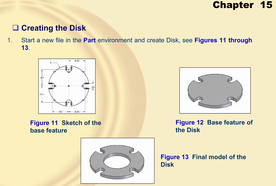
Chapter 15
1. Start a new file in the Part environment and create Disk, see Figures 11 through 13.
Figure 11 Sketch of the base feature
� Creating the Disk
Figure 12 Base feature of the Disk
Figure 13 Final model of the Disk
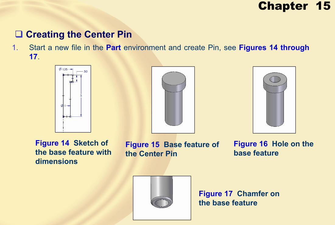
Chapter 15
1. Start a new file in the Part environment and create Pin, see Figures 14 through 17.
Figure 14 Sketch of the base feature with dimensions
� Creating the Center Pin
Figure 15 Base feature of the Center Pin
Figure 16 Hole on the base feature
Figure 17 Chamfer on the base feature
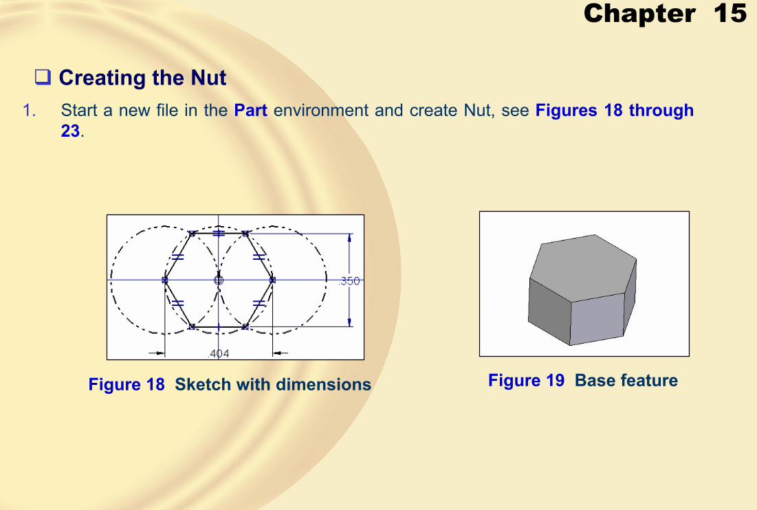
Chapter 15
1. Start a new file in the Part environment and create Nut, see Figures 18 through 23.
Figure 18 Sketch with dimensions
� Creating the Nut
Figure 19 Base feature

Chapter 15
Figure 20 Sketch of the revolved cut Figure 21 Revolved cut on the base feature
Figure 22 Mirror copy of the revolved cut
Figure 23 Final model of the Nut

Chapter 15
1. Assemble all the components, see Figures 24 through 30.
Figure 24 Cylindrical surfaces to be selected for aligning the axes
� Creating the Assembly
Figure 25 Disk assembled with the End Plate

Chapter 15
Figure 26 Face to be selected to add the Insert relationship
Figure 27 Support Pin assembled with the End Plate
Figure 28 Support Pins assembled in the assembly

Chapter 15
Figure 29 Spacer assembled in the assembly
Figure 30 Fixture assembly

Chapter 15
1. Generate the drawing views, see Figure 31.
Figure 24 Drawing views of the assembly
� Generating the Base Drawing Views
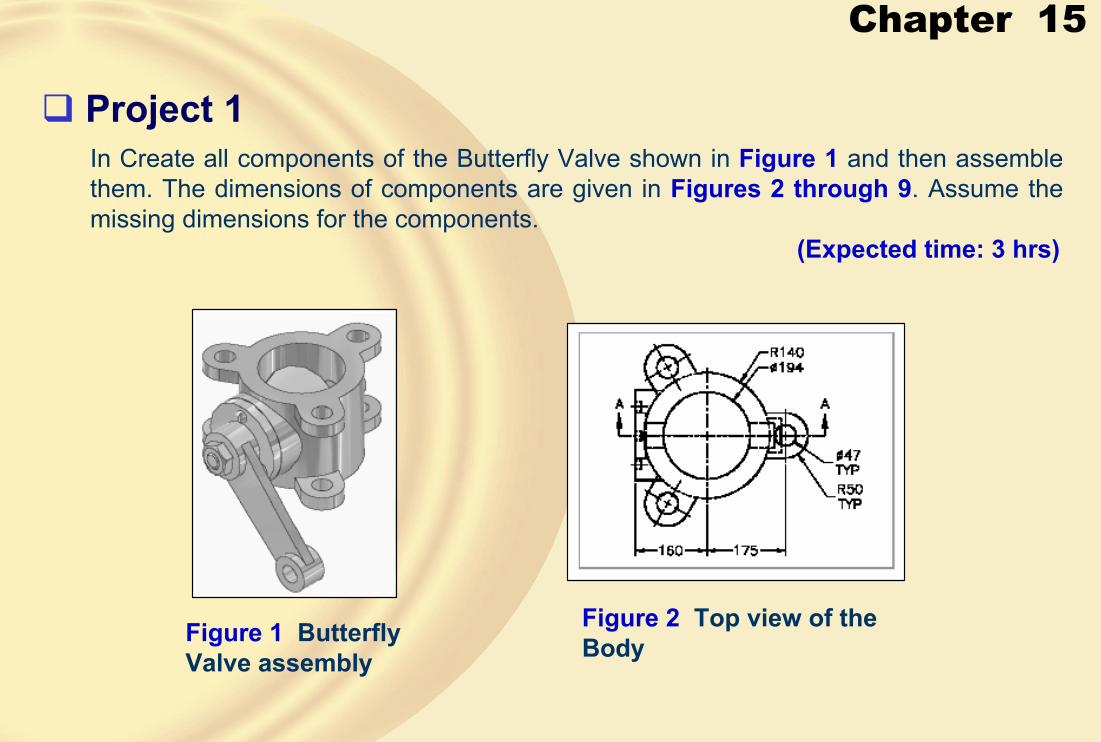
Chapter 15
In Create all components of the Butterfly Valve shown in Figure 1 and then assemble them. The dimensions of components are given in Figures 2 through 9. Assume the missing dimensions for the components.
(Expected time: 3 hrs)
Figure 1 Butterfly Valve assembly
Figure 2 Top view of the Body
� Project 1

Chapter 15
Figure 3 Left side view of the Body
Figure 4 Sectioned front view of the Body
Figure 5 Top view of the Arm Figure 6 Dimensions of the Shaft

Chapter 15
Figure 7 Sectioned front view of the Arm
Figure 8 Dimensions of the Retainer
Figure 9 Dimensions of the Plate, Nut, and Screw