department of defense interface standard - vocal
TRANSCRIPT

DRAFT MIL-STD-188-110B 9 MARCH 2000 SUPERSEDING MIL-STD-188-110A
30 SEPTEMBER 1991
DEPARTMENT OF DEFENSE INTERFACE STANDARD
INTEROPERABILITY AND PERFORMANCE STANDARDS FOR DATA MODEMS
AMSC N/A AREA TCSS
NOT MEASUREMENT SENSITIVE

MIL-STD-188-110B
ii
FOREWORD 1. This Military Standard is approved and mandatory for use by all Departments and Agencies of Defense (DoD) in accordance with DoD Instruction 5000.2, dated 23 February 1991. 2. Beneficial comments (recommendations, additions, deletions) and any pertinent data which may be of use in improving this document should be addressed to: AFCA/ITS, Scott AFB, IL 62225-6343, by using the self-addressed Standardization Document Improvement Proposal (DD Form 1426) appearing at the end of this document, or by letter. 3. As a result of a Joint Chiefs of Staff (JCS) action, standards for all military communications are now being published in a MIL-STD-188 series of documents. The MIL-STD-188 series is subdivided into a MIL-STD-188-100 series covering common standards for tactical and long-haul communications, a MIL-STD-188-200 series covering standards for tactical communications only, and a MIL-STD-188-300 series covering standards for long-haul communications only. Emphasis is being placed on developing common standards for tactical and long-haul communications published in the MIL-STD-188-100 series. 4. This document contains technical standards and design objectives for minimum interface and performance standards pertinent to voice frequency band modulators-demodulators (modems) which operate in both long-haul and tactical communications systems. The terms "system standard" and "design objective (DO)" are defined in FED-STD-1037. In this document, the word "shall" identifies mandatory system standards. The word “should” identifies DOs that are desirable but not mandatory.

MIL-STD-188-110B
iii
CONTENTS PARAGRAPH PAGE FOREWORD ii 1. SCOPE 1 1.1 Scope 1 1.2 Applicability 1 1.3 Application guidance 1 2. APPLICABLE DOCUMENTS 2 2.1 Government Documents 2 2.1.1 Specifications and standards 2 2.1.2 Other Government documents and publications 3 2.2 Non-government publications 4 2.3 Order of precedence 6 3. DEFINITIONS 7 3.1 Terms 7 3.2 Abbreviations and acronyms 8 4. GENERAL REQUIREMENTS 13 4.1 Functional employment 13 4.2 Common Parameters 13 4.2.1 Modulation and data signaling rates and tolerance 13 4.2.2 Logic and signaling sense for binary signals 14 4.2.3 Digital interface characteristics 16 4.2.4 Terminal impedance for quasi-analog signals 16 4.2.5 Quasi-analog signal levels 18 4.2.6 Clock equipment, control, and timing 19 4.3 General design requirements 22 4.3.1 Federal maritime interoperability requirements 22 4.3.2 International interoperability requirements 22 4.4 Data link protocol (optional) 22 5. DETAILED REQUIREMENTS 23 5.1 Frequency shift keying (FSK) data modulators-demodulators
(modems) for single-channel radio equipment 23 5.1.1 Narrow-shift FSK modem 23 5.1.2 Wide-shift FSK modem 23 5.1.3 Speech-plus-telegraph operation 23 5.2 FSK data modems for voice frequency (VF) channel operation 24 5.2.1 FSK data modems for 150 bits per second (bps) or less 24 5.2.2 FSK data modems for 1200 bps or less 25 5.3 HF data modems 26

MIL-STD-188-110B
iv
CONTENTS (continued) PARAGRAPH PAGE 5.3.1 General requirements 26 5.3.2 Serial (single-tone) mode 28 5.3.3 Frequency hopping mode (optional) 49 5.3.4 Robust serial tone for severely degraded HF links (optional) 49 5.4 Wireline data modems 50 5.4.1 General requirements 50 5.4.2 Performance requirements 50 5.5 Data modems for 600 bps or 1200 bps 50 5.6 Data modems for 2400 bps 51 5.6.1 Optional mode 51 5.6.2 Throughput 51 5.7 Data modems for 4800 bps 51 5.7.1 Fallback operation 51 5.7.2 Optional modes 51 5.8 Data modems for 9600 bps 51 5.8.1 Private line operation 51 5.8.2 Fallback operation 51 5.8.3 Switched network operation (U.S. PSN, foreign push-to-talk
(PTT) and Digital Switched Network (DSN) 52 5.9 Data modems with data signaling rates greater than 9600 bps 52 6. NOTES 53 6.1 Intended use 53 6.2 Issue of Department of Defense Index of Specifications and
Standards (DODISS) 53 6.3 Subject term (key word) listing 53

MIL-STD-188-110B
v
LIST OF FIGURES 1 Standard interface between data terminal equipment and
data circuit-terminating equipment 15 2 Serial (single-tone) waveform functional block diagram 29 3 An example of equipment interface block diagram 32 4 FEC encoder block diagram 37 5 State constellation diagram 45 6 Randomizing shift register functional diagram 47 LIST OF TABLES I Reference list for modem applications 13 II Logic and signal sense for binary signals 14 III Tactical switched multi-channel communications subsystems 17 IV Characteristic frequencies of FSK data modems for single-channel
radio equipment 23 V Characteristic frequencies of FSK data modems for single-channel
speech-plus-telegraph operation 24 VI Characteristic frequencies of FSK data modems for 150 bps
or less 24 VII Characteristic frequencies of FSK data modems for 1200 bps
or less 25 VIII Error correcting coding, frequency hopping operation 36 IX Error-correcting coding, fixed frequency operation 38 X Interleaver matrix dimensions 39 XI Bits-per-channel symbol 40 XII Modified-Gray decoding at 2400 bps and 4800 bps 41 XIII Modified-Gray decoding at 75 bps (fixed frequency) and
1200 bps 41 XIV Channel symbol mapping for 75 bps 42 XV Assignment of designation symbols D1 and D2 44 XVI Conversion of two bit count value to three bit symbol 44 XVII Channel symbol mapping for sync preamble 46 XVIII Frequency-hopping operation waveform characteristics 48 XIX Fixed-frequency operation waveform characteristics 48 XX Serial (single-tone) mode minimum performance 49

MIL-STD-188-110B
vi
LIST OF APPENDIXES A. 16-TONE DIFFERENTIAL PHASE-SHIFT KEYING
(DPSK) MODE 54 B. 39-TONE PARALLEL MODE 62 C. HF DATA MODEM WAVEFORMS FOR DATA RATES
ABOVE 2400 bps 89 D. SUBNETWORK INTERFACE 114 E. DATA LINK PROTOCOL 117

MIL-STD-188-110B
1
1 SCOPE 1.1 Scope. This document establishes mandatory technical standards and design objectives (DO) that are necessary to ensure interoperability and to promote performance among data modulators-demodulators (modems) used in the voice frequency (VF) band of long-haul and tactical communications systems. This document also provides guidance to the designers of new data modems that incorporate characteristics not yet standardized by specifying the technical characteristics of data modems currently in the inventory. The purpose of this guidance is to ensure attainment of minimum acceptable performance and maximum interoperability between existing and future data modems with specified transmission channel conditions. 1.2 Applicability. These standards are mandatory within the Department of Defense (DoD) in the design, development and engineering of new communications facilities for both narrowband and wideband long-haul and tactical systems. In some cases, reference is made to other documents that provide standards for specific applications. It is not intended that existing systems be immediately converted to comply with the requirements of these standards. New systems, and those undergoing major modification or rehabilitation, shall conform to these standards subject to current procurement regulations. This document is applicable to the design and development of new data modems with standard data signaling rates up to and including 19200 bits per second (bps) used in long-haul and tactical communications systems. This document is not applicable to high frequency (HF) data modems used in the Tactical Digital Information Link (TADIL) A. The HF data modem standards for TADIL A are published in MIL-STD-188-203-1. 1.3 Application guidance. Requirements in this document, if applied as intended, shall ensure interoperability and performance of data modems having the same or similar functions. The variety of data modems shall be limited to that which is essential to effectively support the missions of the military forces. It is not intended that the standards contained in this document inhibit advances in communications technology. Such advances are encouraged by including DOs which should be used if economically feasible. Additionally, standardizing parameter values but not the technology that may be used to meet these parameter values facilitates such advances. Mandatory equipment parameter values and requirements are specified by the use of the word “shall". Minimum performance requirements for the high frequency (HF) serial (single-tone) and parallel tone modem waveforms are specified in table XX and table B-XII, respectively. The specified values shown represent HF modem performance under ideal test conditions. To identify the minimum acceptable performance available to users, many factors, including operational test and evaluation must be considered.

MIL-STD-188-110B
2
2 APPLICABLE DOCUMENTS 2.1 Government documents. 2.1.1 Specifications and standards. The following specifications and standards form a part of this document to the extent specified herein. Unless otherwise specified, the issues of these documents are those listed in the issue of the Department of Defense Index of Specifications and Standards (DODISS) and supplements thereto, cited in the solicitation (see 6.2). SPECIFICATIONS
MIL-C-28883 Military Specification for the Advanced Narrowband Digital Voice Terminal (ANDVT) Tactical Terminal (TACTERM) CV-3591 and Ancillaries
STANDARDS FEDERAL
FED-STD-1035 Coding, Modulation and Transmission Requirements for Single Channel Medium and High Frequency Radiotelegraph Systems Used in Government Maritime Mobile Telecommunications.
FED-STD-1037 Glossary of Telecommunication Terms FEDERAL INFORMATION PROCESSING STANDARDS (FIPS)
FIPS-PUB-133 Coding and Modulation Requirements for Nondiversity 2400 Bit/Second Modems
FIPS-PUB-134-1 Coding and Modulation Requirements for Nondiversity 4800 Bit/Second Modems
FIPS-PUB-135 Coding and Modulation Requirements for Nondiversity 9600 Bit/Second Modems
FIPS-PUB-136 Coding and Modulation Requirements for Duplex 600 and 1200 Bit/Second Modems
FIPS-PUB-22-1 Synchronous Signaling Rates Between Data Terminal Equipment and Data Circuit-Terminating Equipment Utilizing 4 kHz Circuits

MIL-STD-188-110B
3
MILITARY
MIL-STD-188-114 Electrical Characteristics of Digital Interface Circuits MIL-STD-188-141 Interoperability and Performance Standards for Medium
and High Frequency Radio Equipment MIL-STD-188-148 (S) Interoperability Standard for Anti-Jam (AJ)
Communications in the High Frequency Band (2-30 MHz) (U)
MIL-STD-188-200 System Design and Engineering Standards for Tactical Communications
(Unless otherwise indicated, copies of Federal and military specifications and standards are available from the Standardization Document Order Desk, 700 Robbins Avenue, Building 4, Section D, Philadelphia, PA 19111.) 2.1.2 Other Government documents and publications. The following other Government documents and publications form a part of this document to the extent specified herein. Unless otherwise specified, the issues are those cited in the solicitation. FEDERAL COMMUNICATIONS COMMISSION (FCC)
FCC Rules and Regulations Part 68
Connection of Terminal Equipment to the Telephone Network
(Application for copies should be addressed to the U.S. Government Printing Office; Superintendent of Documents, Public Documents Department, Washington, D.C. 20402.) DEPARTMENT OF DEFENSE (DoD)
DoD Instruction 5000.2
Mandatory Procedures for Major Defense Acquisition Programs (MDAPS) and Major Automated Information System (MAIS) Acquisition Programs
DoD Directive 4120.3-M
Defense Standardization Program (DSP) Policies and Procedures
DoD JTA Joint Technical Architecture (Copies can be obtained at http://www.jta.itsi.disa.mil/)
DEFENSE INFORMATION SYSTEMS AGENCY CIRCULARS (DISAC)
DISAC 300-175-9 DII Operating Maintenance Electrical Performance Standards

MIL-STD-188-110B
4
(Copies can be obtained at http://www.disa.mil/pubs/circulars/circular.html) 2.2 Non-government publications. The following documents form a part of this document to the extent specified herein. Unless otherwise specified, the issues of the documents that are DoD adopted are those listed in the issues of the DODISS cited in the solicitation. Unless otherwise specified, the issues of documents not listed in the DODISS are the issues of the documents cited in the solicitation (see 6.2). INTERNATIONAL STANDARDIZATION DOCUMENTS NORTH ATLANTIC TREATY ORGANIZATION (NATO) STANDARDIZATION AGREEMENTS (STANAG)
STANAG 4197 Modulation and coding characteristics that must be common to assure interoperability of 2400 bps linear predictive encoded digital speech transmitted over HF radio facilities
STANAG 4198 Parameter and coding characteristics that must be common to assure interoperability of 2400 bps linear predictive encoded digital speech
STANAG 4203 Technical Standard for Single Channel HF Radio Equipment
STANAG 4285 Characteristics of 1200/2400/3600 bps single tone modulators/demodulators for HF radio links
STANAG 4291 Modulation and coding characteristics that must be common to assure interoperability of 2400 bps wireline modems for use in narrow-band secure voice systems
STANAG 4415 Characteristics of a robust, non-hopping serial tone modulator/demodulator for severely degraded HF radio links
STANAG 4529 Characteristics of Single-Tone Modulators/Demodulators for Maritime HF Radio Links with 1240 Hz bandwidth
STANAG 4481 Minimum technical standards for naval HF shore-to-ship broadcast systems
STANAG 5031 Introduction of modern radio equipment for naval HF, MF, and LF shore-to-ship broadcasts
STANAG 5035 Introduction of an improved system for maritime air communications on HF, LF, and UHF

MIL-STD-188-110B
5
QUADRIPARTITE STANDARDIZATION AGREEMENTS (QSTAG)
QSTAG 303 Frequency shift standards for HF/RATT and VHF/RATT operation
(Application for copies should be addressed to: Standardization Document Order Desk, 700 Robbins Avenue, Building 4, Section D, Philadelphia, PA 19111.) INTERNATIONAL TELECOMMUNICATION UNION (ITU)
ITU-R F.520-2 Use of high frequency ionospheric channel simulators
ITU-T V.22 1200 bits per second duplex modem standardized for use in the general switched telephone network and on point-to-point 2-wire leased telephone-type circuits
ITU-T V.22 bis 2400 bits per second duplex modem using the frequency division technique standardized for use on the general switched telephone network and on point-to-point 2-wire leased telephone-type circuits
ITU-T V.25 Automatic answering equipment and general procedures for automatic calling equipment on the general switched telephone network including procedures for disabling of echo control devices for both manually and automatically established calls
ITU-T V.26 2400 bits per second modem standardized for use on 4-wire leased telephone-type circuits
ITU-T V.26 bis 2400/1200 bits per second modem standardized for use in the general switched telephone network
ITU-T V.27 ter 4800/2400 bits per second modem standardized for use in the general switched telephone network
ITU-T V.29 9600 bits per second modem standardized for use on point-to-point 4-wire leased telephone-type circuits
ITU-T V.32 A family of 2-wire, duplex modems operating at data signalling rates of up to 9600 bit/s for use on the general switched telephone network and on leased telephone-type circuits
(Application for copies should be addressed to the General Secretariat, International Telecommunication Union, Place des Nations, CH-1211 Geneva 20, Switzerland or the U.S. Department of Commerce, National Technical Information Service, 5285 Port Royal Road, Springfield,VA 22161.)

MIL-STD-188-110B
6
TELECOMMUNICATIONS INDUSTRIES ASSOCIATION (TIA) (formerly Electronic Industries Association (EIA))
EIA-496 Interface Between Data Circuit-Terminating Equipment (DCE) and the Public Switched Telephone Network (PSTN)
(Application for copies should be addressed to the Telecommunications Industries Association (TIA), 2500 Wilson Boulevard, Arlington, VA 22201, ATTN: Standard Sales Office (Non-Government standards and other publications are normally available from the organizations that prepare or distribute the documents. These documents also may be available in or through libraries or other informational services.) 2.3 Order of precedence. In the event of a conflict between the text of this document and the references cited herein, the text of this document takes precedence. Nothing in this document, however, supersedes applicable laws and regulations unless specific exemption has been obtained.

MIL-STD-188-110B
7
3 DEFINITIONS 3.1 Terms. Definitions of terms used in this document shall be as specified in FED-STD-1037. For the purposes of this standard, definitions are provided for the following terms, some of which have been repeated, from FED-STD-1037 for the convenience of the reader. Automatic link establishment (ALE). The capability of an HF radio station to make contact, or initiate a circuit, between itself and another specified radio station, without operator assistance and usually under processor control.
NOTE: ALE techniques include automatic signaling, selective calling, and automatic handshaking. Other automatic techniques that are related to ALE are channel scanning and selection, link quality analysis (LQA), polling, sounding, message store and forward, address protection, and anti-spoofing.
Balanced to ground. Pertaining to electrical symmetry with respect to a common ground. Break-in signal. A signal used to interrupt the other user and take control of the circuit. Clear-to-send (CTS) signal. The control signal generated by the transmitting modem on the CTS connection to denote a state of readiness for transmission. The CTS signal is a response to the request-to-send (RTS) signal from the transmitting device Code rate. The ratio of the number of information symbols (k) to the total number of encoded symbols (n) in a code (i.e., the ratio of k/n). Dead time. In hopping, the portion of a hop dwell period in which no transmission occurs. Dwell period. The maximum amount of time a transmission occurs on a particular frequency. Galois field. An arithmetic system, containing a set of symbol elements with two operations (and their inverses) for combining pairs of elements. In-band diversity combining. A combining of two or more signals which uses frequencies within the bandwidth of the information channel and carries the same information received with the objective of providing a single resultant signal that is superior in quality to any of the contributing signals. Mode. An available format in a data modem supporting multi-waveform capability. Narrowband. At HF radio frequencies (1.5 - 30 MHz) the nominal voice frequency (VF) bandwidth allocated for single channel radio (i.e., 3 kHz). Nominal bandwidth. The widest band of frequencies, inclusive of guard bands, assigned to a channel.

MIL-STD-188-110B
8
Preamble code. A short sequence of symbols at the beginning of a coded sequence used to achieve synchronization. Request-to-send (RTS) signal. The control signal generated by the transmitting terminal on the RTS connection to denote a request for transmission. Secure voice. A voice communication that is protected against compromise through the use of an encryption system. Transmission level point (TLP). A point in a transmission system at which the ratio, in decibels, of the power of the test signal at that point to the power of the test signal at a reference point, is specified. Unbalanced to ground. Pertaining to electrical asymmetry with respect to a common ground.
NOTE: Frequently, the term "unbalanced" describes a circuit, one side of which is grounded.
Wideband. At HF radio frequencies (1.5 - 30 MHz) a bandwidth larger than 3 kHz. 3.2 Abbreviations and acronyms. Abbreviations and acronyms used in this document are defined below. Those that are also found in FED-STD-1037 have been included for the convenience of the reader.
ABCA American, British, Canadian, Australian (armies)
AJ anti-jamming
ALE automatic link establishment
ANC automatic node controller
ANDVT Advanced Narrowband Digital Voice Terminal
ANSI American National Standard Institute
ARQ Automatic repeat request
AUTODIN Automatic Digital Network
Bd Baud
BER Bit error ratio

MIL-STD-188-110B
9
bps Bits per second
BW Bandwidth
CCIR International Radio Consultative Committee
CTS Clear to send
CTX Clear to transmit
CVSD Continuously variable slope delta (modulation)
dB Decibel(s)
dBm dB referred to one milliwatt
dBm0 Noise power in dBm referred to or measured at 0 TLP
DCD Data carrier detect
DCE Data circuit-terminating equipment
DCS Defense Communications System
DISA Defense Information Systems Agency
DISAC Defense Information Systems Agency Circular
DO Design objective
DoD Department of Defense
DODISS Department of Defense Index of Specifications and Standards
DPSK Differential phase shift keying
DSN Digital Switched Network
DTE Data terminal equipment
EIA Electronic Industries Association
EMI Electromagnetic interference
EOM End of message

MIL-STD-188-110B
10
FCC Federal Communications Commission
FDM Frequency-division multiplexing
FEC Forward error correction
FED-STD Federal Standard
FIPS Federal Information Processing Standards
FSK Frequency-shift keying
GF Galois field
HF high frequency
Hz Hertz
ISB independent sideband
ITU International Telecommunication Union
JCS Joint Chiefs of Staff
kHz kilohertz (1,000 hertz)
km kilometer (1,000 meters)
LF low frequency
log Logarithm
LQA link quality analysis
LSB least significant bit
MF medium frequency
MGD modified-Gray decoder
MHz megahertz (1,000,000 hertz)
MIL-STD military standard
MM maritime mobile

MIL-STD-188-110B
11
modem modulator-demodulator
ms millisecond(s)
MSB most significant bit
NATO North Atlantic Treaty Organization
NMCS National Military Command System
PCM pulse-code modulation
PSK phase-shift keying
PSN public switched network
PTT push-to-talk
QAM quadrature amplitude modulation
QDPSK quadrature differential phase-shift keying
QSTAG Quadripartite Standardization Agreement
RA receive audio
RATT radio teletypewriter system
RC receive clock
RCE radio communications equipment
RD receive data
rms root-mean-square
RS receive (HF radio) signal
RTE radio terminal equipment
RTS request to send
RTX request to transmit
s second(s)

MIL-STD-188-110B
12
(S) SECRET
SNR signal-to-noise ratio
STANAG Standardization Agreement (NATO)
sync Synchronization
TA transmit audio
TT tactical terminal
TC transmit clock
TADIL tactical digital information link
TD transmit data
TDM time-division multiplexing
TIA Telecommunications Industries Association
TLP transmission level point
TS transmit (HF radio) signal
TX Transmit
(U) UNCLASSIFIED
UHF ultra high frequency
VP voice frequency
VHF very high frequency
VLF very low frequency
0 TLP zero transmission level point(s)

MIL-STD-188-110B
13
4 GENERAL REQUIREMENTS 4.1 Functional employment. Data modulators-demodulators (modems) are employed in long-haul and tactical communications systems and subsystems. Delineation between long-haul and tactical communications systems can be found in Federal Standard (FED-STD)-1037. Data modems employ a variety of techniques for converting digital signals into quasi-analog signals for transmission over analog channels. Various modulation techniques have been standardized and no single optimum technique has been found for all applications. This section covers general requirements for both long-haul and tactical data modems operating over voice frequency (VF) and radio channels. A representative list is given in table I with the modulation types and data rates noted for each channel category listed. This table also provides a cross-reference to section 5 requirements.
NOTE: Very low frequency (VLF) radio modems are not standardized.
TABLE I. Reference list for modem applications.
Channel Modulation Type
Data Rate (bps) Reference Paragraph
VF (4 kHz) FSK < 150 5.2.1 VF (4 kHz) FSK < 1200 5.2.2 VF (4 kHz) (various) 600 or 1200 5.5 VF (4 kHz) (various) 2400 5.6 VF (4 kHz) DPSK 4800 5 7 VF (4 kHz) QAM 4800, 7200, 9600 5.8 VF (4 kHz) (various) > 9600 5.9 LF radio (3 kHz) FSK < 150 5.1 MM radio (3 kHz) FSK < 150 5.1.1 HF radio (3 kHz) FSK <150 5.1.2 HF radio (3 kHz) PSK 75-4800 5.3.2 UHF radio (3 kHz) FSK < 150 5.1
4.2 Common parameters. All data modems shall comply with the applicable requirements of 4.2.1 through 4.2.6. 4.2.1 Modulation and data signaling rates and tolerance. The modulation rates expressed in baud (Bd) and the data signaling rates expressed in bits per second (bps) at the standard interfaces shown on figure 1 shall be as listed below. These rates, with the exception of 50 Bd or bps, 75, 150, 300, and 600 bps, comply with the requirements of FIPS-PUB-22-1:
a. 50 Bd or bps b. 75 X 2m Bd or bps, up to and including 9600 Bd or bps, where m is a positive integer 0,
1, 2, … 7.

MIL-STD-188-110B
14
NOTE: FIPS-PUB-22-1 adopts American National Standards Institute (ANSI/X3.1-1987) synchronous signaling rates. Other rates (i.e., 3600, 7200, 12000 and 19200) are not standardized. NOTE: The data signaling rate is expressed in bps; the modulation rate is expressed in Bd. Data signaling rates in bps and modulation rates in Bd are the same only for binary signaling. Data signaling rates in bps relate to modulation rates in Bd through the following equation: Data signaling rates (bps) = k x modulation rates (Bd) where k = log2M is the number of binary digits per modulation symbol, and M is the number of modulation symbols.
Except where specified otherwise, signaling rates shall not deviate from the nominal values by more than +0.01%. 4.2.2 Logic and signaling sense for binary signals. For data and timing circuits, the signal voltage with respect to signal ground shall be negative to represent the MARK condition and positive to represent the SPACE condition. The significant conditions and other logic and signal states shown in table II shall apply to telegraph and data transmission. An alternative capability shall be provided to interface with equipment that accepts positive mark and negative space signals.
TABLE II. Logic and signal sense for binary signals.
Application Condition Condition Voltage to signal ground Negative (-) Positive (+) Conventional term Mark Space Binary digit value One (1) Zero (0) Timing signal state Off On FSK signal state Lower frequency Higher frequency

MIL-STD-188-110B
15
Notes: 1. DTE = Data Terminal Equipment DCE = Data Circuit - Terminating Equipment. 2. DTE and DCE may include data adapters, modems, error control algorithm, encryption
devices, control units, and other equipment, as required. 3. DTE and DCE can be combined in a single unit device. 4. The transmission channel may include nodes and single or multi-channel transmission
equipment. 5. Modulation rates and data signaling rates at the standard interface are specified in 4.2.1. FIGURE 1. Standard interface between data terminal equipment and data circuit-terminating equipment.
DTE DCE DCE DTE
Dat a Tra nsmissio nCircuit(Digit al or Q u asi-A n alo g Sig n als)
Transmissi on Channel
S tan dard Int erface(Digi t al or Quasi-A n alo g)
S tan dard Int erface(Digi t al or Quasi-A n alo g)

MIL-STD-188-110B
16
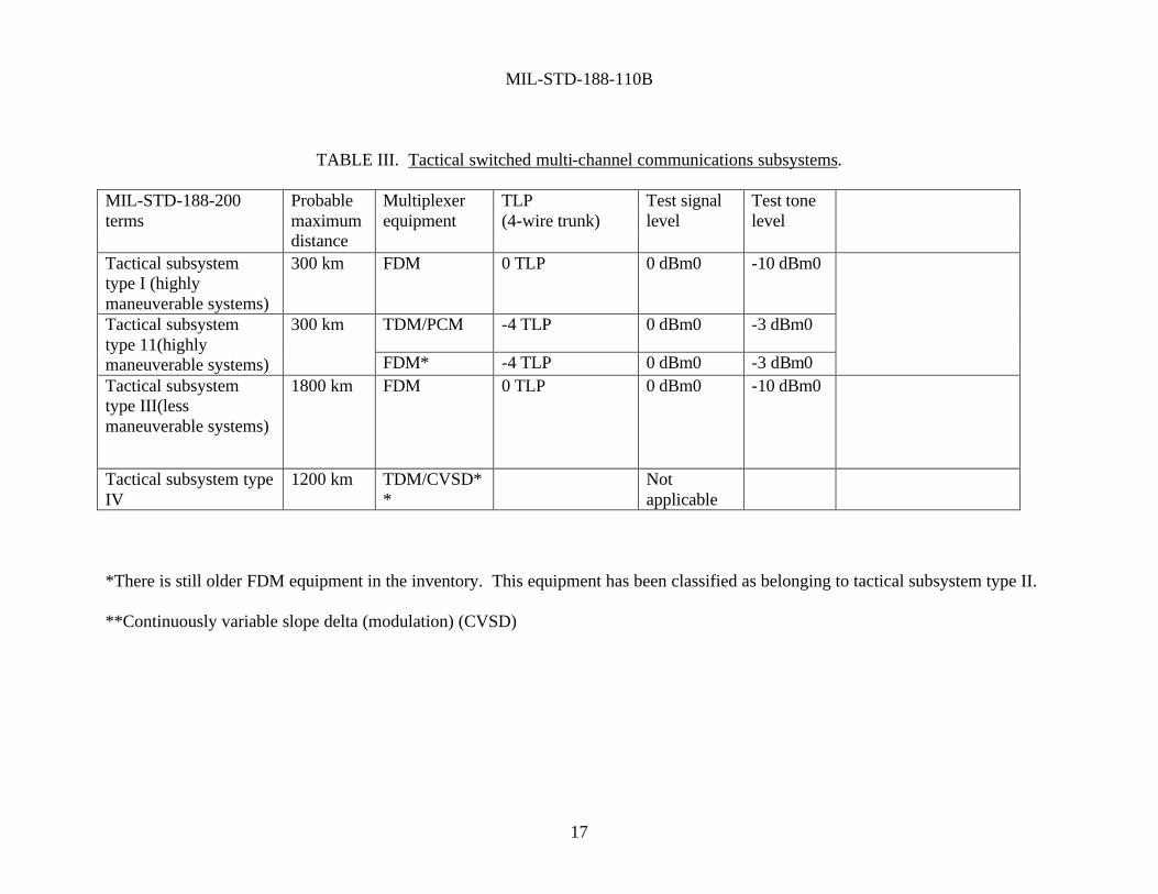
4.2.3 Digital interface characteristics. The electrical characteristics of the digital interface at the modulator input and the demodulator output shall be in accordance with the applicable requirements of military standard MIL-STD-188-114. 4.2.4 Terminal impedance for quasi-analog signals. 4.2.4.1 Modems used in multi-channel subsystems. For modems used in long-haul systems and in tactical subsystem types I, II, and III (see table III), the terminal impedance at the modulator output and the demodulator input shall be 600 ohms, balanced to ground, with a minimum return loss of 26 decibels (dB) against a 600-ohm resistance over the frequency band of interest. The electrical symmetry shall be sufficient to suppress longitudinal currents to a level which is at least 40 dB below reference level (-40 dB referred to one milliwatt measured at zero transmission level point (dBm0)). 4.2.4.2 Modems used in single-channel radio subsystems. For modems used with radio equipment of single-channel radio subsystems, the terminal impedance at the modulator output shall be 150 ohms, unbalanced to ground, with a minimum return loss of 20 dB against a 150-ohm resistance over the frequency band of interest. The terminal impedance at the demodulator input shall be 600 ohms, balanced to ground, with a minimum return loss of 26 dB against a 600-ohm resistance over the frequency band of interest. The electrical symmetry shall be sufficient to suppress longitudinal currents to a level that is at least 40 dB below reference level (-40 dBm0).
NOTE: As a design objective (DO), the terminal impedance at the modulator output should be 600 ohms, balanced to ground, with a minimum return loss of 26 dB against a 600-ohm resistance over the frequency band of interest. The electrical symmetry should be sufficient to suppress longitudinal currents to a level that is at least 40 dB below reference level (-40 dBm0). NOTE: A terminal impedance balanced to ground is recommended for equipment (radios, data modems, etc.) operating in an environment that has a high electromagnetic interference (EMI) level, such as in aircraft and tanks. Measurements have shown that an electrical noise-rejection improvement of up to 20 dB can be achieved for balanced terminations, compared with unbalanced terminations.
MIL-STD-188-110B
17
TABLE III. Tactical switched multi-channel communications subsystems.
MIL-STD-188-200 terms
Probable maximum distance
Multiplexer equipment
TLP (4-wire trunk)
Test signal level
Test tone level
Tactical subsystem type I (highly maneuverable systems)
300 km FDM 0 TLP 0 dBm0 -10 dBm0
TDM/PCM -4 TLP 0 dBm0 -3 dBm0 Tactical subsystem type 11(highly maneuverable systems)
300 km
FDM* -4 TLP 0 dBm0 -3 dBm0
Tactical subsystem type III(less maneuverable systems)
1800 km FDM 0 TLP 0 dBm0 -10 dBm0
Tactical subsystem type IV
1200 km TDM/CVSD**
Not applicable
*There is still older FDM equipment in the inventory. This equipment has been classified as belonging to tactical subsystem type II. **Continuously variable slope delta (modulation) (CVSD)

MIL-STD-188-110B
18
4.2.5 Quasi-analog signal levels. 4.2.5.1 Modems used in multi-channel subsystems. For modems used in long-haul systems and in tactical subsystem types I, II, and III (see table III), the quasi-analog signal level at the modulator output shall be adjustable from at least -18 dB referred to one milliwatt (dBm) to +3 dBm. The difference in the output levels between the MARK and SPACE binary signals shall be less than 1 dB. The demodulator shall be capable of operating, without degradation of performance, with a received quasi-analog signal level ranging from at least -35 dBm to +3 dBm.
a. For long-haul systems and tactical subsystem types I and III, the transmitted quasi-analog signal level of telegraph and data equipment (modem, multiplexer, etc.) shall be adjustable from at least -18 dBm to +3 dBm to provide -13 dBm0 (e.g., -13 dBm at a zero transmission level point (0 TLP)) at the input terminals of a data trunk or switch. For multitone data signals, the level of each data tone with reference to -13 dBm, shall be equal to -13 - (10 log t), measured in dBm, where t is the number of tones.
b. For tactical subsystem type II, the transmitted quasi-analog signal level of telegraph and data equipment (modem, multiplexer, etc.), shall be adjustable from at least -18 dBm to +3 dBm to provide -6 dBm0 (e.g., -10 dBm at a - 4 TLP) at the input terminals of a data trunk or switch. For multitone data signals, the level of each data tone with reference to -10 dBm shall be equal to -10 - (10 log t), measured in dBm, where t is the number of tones.
NOTE l: The formulas -13 - (10 log t) and -10 - (10 log t) assume a random phase distribution for the data tones of a multitone modem. The multitone phases may not be distributed randomly if the multitone signals are derived from a common frequency source. In such a case, the probability of tones adding in phase increases. This can cause the composite multitone signal to have a higher level than that given by the formulas and thus, could overload frequency-division multiplexing (FDM) equipment. NOTE 2: The standard data level of -6 dBm0 applies also to time-division multiplexing/pulse code modulation (TDM/PCM) equipment even if this type of equipment is not subject to the same overload problems as FDM equipment. A data level that exceeds the standard level will cause clipping of the peak amplitudes of quasi-analog signals by the PAM equipment, resulting in unsatisfactory data transmission. NOTE 3: The different transmitted quasi-analog signal level of tactical subsystem type II (3 dB higher), as compared to the level of long-haul systems and tactical subsystem types I and III, must be accompanied when interconnecting VF channels of tactical subsystem type II with VF channels of the other subsystems or systems. NOTE 4: Compliance with 4.2.5.1 does not require the quasi-analog signal level to be continuously adjustable. The specified signal level may be obtained in incremental

MIL-STD-188-110B
19
steps, continuously, or by a combination of both methods. The methods of adjustment will be determined in applicable equipment specifications.
4.2.5.2 Modems used in single-channel radio subsystems. Standards for the quasi-analog signal levels of modulators and demodulators are documented in MIL-STD-188-141. 4.2.6 Clock equipment, control, and timing. All data modems shall have the capability to accept external timing signals. The clock is the device which provides the time base for controlling operation of digital equipment. An equipment clock provides the peculiar needs of its equipment and in some cases may control the flow of data at its equipment interface. A master or station clock, regardless of its physical location, controls two or more equipments which are linked together as a system. The following subparagraphs, 4.2.6.1 through 4.2.6.3.1, are primarily concerned with master or Station clocks. 4.2.6.1 Transmission modes. All future communications equipment requiring a stable clock or precise character interval control shall make provisions for operating from station clocks in any or all of the following states;, specified in subparagraphs 4.2.6.1.1 through 4.2.6.1.3.1. 4.2.6.1.1 Bit synchronous. In bit synchronous operation, clock timing shall be delivered at twice the data modulation rate. (For this purpose "data" includes information bits plus all bits added to the stream for whatever purpose they may serve in the system; i.e., error control, framing. . .etc.). The device shall release one bit within the duration of one clock cycle. It shall be assumed that, during periods of communication difficulty, a clock signal might be delivered to a send device occasionally or not at all for periods extending to hours. During periods when the sending equipment has no traffic to send, an idle pattern or all "ones" may be transmitted. 4.2.6.1.2 Bit-by-bit asynchronous. In bit-by-bit asynchronous operation It is assumed that rapid manual, semiautomatic or automatic shifts in the data modulation rate will be accomplished by gating or slewing the clock modulation rate. It is possible that equipment may be operated at 50 bps one moment and the next moment at 1200 bps or 2400 bps, etc. It shall be assumed that, during periods of communication difficulty, a clock signal might be delivered to a send device occasionally or not at all for periods extending to hours. During periods when the sending equipment has no traffic to send, an idle pattern or all "ones" may be transmitted. 4.2.6.1.3 Character interval synchronous. In character interval synchronized equipment, any character interval from 4 to 16 unit intervals per character interval shall be permitted. It is assumed that, having programmed a given facility for a particular character interval, no other character interval operation would be expected except by reprogramming. An example of such operation would be a 7.0 units per character interval tape reader being stepped at 8.0 units per character interval.

MIL-STD-188-110B
20
4.2.6.2 Clock characteristics. 4.2.6.2.1 Modulation rates. The standard clock modulation rates for compatibility with modulation or data signaling rates shall be two times the standard rates specified in subparagraph 4.2.1. 4.2.6.2.2 Modulation rate stability. The stability of synchronized or crook timing supplied in all synchronous digital transmission, switching, terminal, and security equipment shall be sufficient to ensure that synchronization is maintained within ±25 percent of the unit interval between transmitted and received signals for periods of not less than 100,000 consecutive seconds. 4.2.6.2.3 Modulation rate phase adjustment. Means shall be provided in all digital transmission, switching, terminal, and security equipment so that, at the applicable modulation rates, a shift in phase of the incoming data stream with relation to the clocking pulse shall be possible over a period of three unit intervals (i.e., a shift of 1.5 unit intervals early or late from theoretical center of the unit interval at the applicable modulation rate). 4.2.6.2.4 Output signal. The output of the clock shall be an alternating symmetrically-shaped wave at the required clock modulation rate. In the case of an unbalanced digital interface, the clock output signal shall comply with the voltage and wave-shaping requirement of subparagraphs 4.3.1.3.3.4 and 4.3.1.3.3.5, respectively. In the case of a balanced digital interface, the clock output signal shall comply with the voltage requirements of subparagraph 4.3.1.3.4.4 and shall contain no points of inflection prior to reaching the maximum amplitudes. When the clock is quiescent, the clock signal state shall be negative. 4.2.6.2.5 Clock period. A clock period or cycle is defined as having one half-cycle of positive polarity (sense) and one half-cycle of negative polarity (sense). The duty cycle shall be 60 percent ±1.0 percent. Thus, in the binary sense, each clock period or cycle is composed of two clock unit intervals, and it follows that a clock rate of 50 Hz is a clock modulation rate of 100 Bd. 4.2.6.3 Clock/data phase relationship. Arrangements which may be used to supply clock pulses to sources and sinks are shown in subparagraph 4 3.1.6.3.1. Typical standard arrangements are shown from which one may be selected to meet a specific application. For those digital devices operated at dc baseband which are interconnected by metallic wire (or other equipment which provides in effect the same function as a metallic wire), the following clock/data phase relationships apply if, and only if, interface circuit lengths permit. It is noted that, due to signal propagation delay time differences over different dc wire circuits or dc equivalent circuits at data modulation rates higher than 2400 Bd, there may be a significant relative clock/data phase shift which must be adjusted in accordance with subparagraph 4.3.1.6.2.3. Practical operating experience indicates that typical multiple pair paper cable or polyvinyl chloride (PVC) insulated exchange grade telephone cable may be expected to function at modulation rates of 4800 Bd data/ 9600 Bd clock at distances up

MIL-STD-188-110B
21
to 3000 cable feet without any need for concern over relative pulse shift or noise if the standard low level digital interface is applied to both clock and data signals in accordance with subparagraph 4 3.1.3. All data transition emitted by a source under direct control of an external clock shall occur on (be caused by) negative to positive transitions of that clock. The design objective is a minimum delay between the clock transition and the resulting data transition, but in no case shall this delay exceed 12.5 percent of the duration of the data unit interval. For each equipment, once this delay is fixed in hardware, it shall be consistent within ±1 percent of itself for each clock transition. These delay limits shall apply directly at the driver interface. Sampling of the data signal by the external clock at a sink interface shall occur on (be caused by) positive to negative clock transitions. When the clock is used for controlling intermittent data transmission, data may not change state except when requested by a negative to positive clock transition. The quiescent state of the clock shall be at negative voltage. The quiescent state of the data shall be that state resulting from the last negative to positive clock transition. The phase relationship between external clock and data is not specified for devices in which the external clock is related only indirectly to the source data; for example, to maintain synchronism between a data source and data sink for a signal with a constant modulation rate. However, whatever the phase delay, It shall be consistent to within +/- 1 percent at the data unit interval at the applicable modulation rate. If the clock at twice the modulation rate at the same data is also supplied as an output, then data transitions shall coincide within +/- 1 percent of the data unit interval with the negative to positive transitions of the output clock (see Figure 4. 3-9). Direct control means control of the data by a clock signal at twice the modulation rate of the data. Indirect control means use of a clock at some higher standard modulation rate; e.g., 4, 8, 128 times the modulation rate. 4.2.6.3.1 Standard arrangements for clock/data phase relationship. TBD.

MIL-STD-188-110B
22
4.3 General design requirements. The general design requirements of 4.3.1 through 4.3.2.3 involve documents outside of the mandatory MIL-STD-188 series. Extreme care must be used to ensure that the provisions, selected from these documents as applicable to a given design task, are tailored in accordance with the policies of Department of Defense (DoD) Directive 4120.21. 4.3.1 Federal maritime interoperability requirements. Ship-to-ship and shore-to-ship medium frequency (MF) and high frequency (HF) radio teletypewriter system (RATT) operation shall be in accordance with the requirements of FED-STD-1035. 4.3.2 International interoperability requirements. 4.3.2.1 Shore-to-ship broadcast systems. For interoperation with North Atlantic Treaty Organization (NATO) member nations, the electrical characteristics of data modems employed in shore-to-ship broadcast systems shall be in accordance with the applicable requirements of NATO Standardization Agreement (STANAG) 5031. 4.3.2.2 Maritime air communications systems. For interoperation with NATO member nations, the electrical characteristics of data modems employed in maritime air communication systems shall be in accordance with the applicable requirements of STANAG 5035. 4.3.2.3 Radio teletypewriter systems. For interoperation among American, British, Canadian, Australian (ABCA) armies, the electrical characteristics of data modems employed in HF and very high frequency (VHF) RATT operations shall comply with the applicable requirements of Quadripartite Standardization Agreement (QSTAG)-303.
NOTE: The applicable characteristics of data modems standardized in this document comply with STANAG 5031, STANAG 5035, and QSTAG-303.
4.4 Data link protocol (optional). When an ARQ protocol is used it shall be in accordance with Appendix E.

MIL-STD-188-110B
23
5 DETAILED REQUIREMENTS
5.1 Frequency shift keying (FSK) data modulators-demodulators (modems) for single-channel
radio equipment. Non-diversity FSK modems used primarily with single-channel (3 kHz) radio equipment shall comply with the applicable requirements of 4.2, 4.3, 5.1.1, 5.1.2, and 5.1.3.
NOTE: The waveform requirements in this paragraph apply when backward compatibility and interoperability are necessary.
Table IV shows characteristic frequencies of the various FSK modems for different radio channels.
TABLE IV. Characteristic frequencies of FSK data modems for single-channel radio equipment.
Channel Mark frequency
(Hz) Center frequency
(Hz) Space frequency
(Hz) LF radio 915 1000 1085
MM radio 1615 1700 1785 HF radio 1575 2000 2425
UHF radio 500 600 700 5.1.1 Narrow-shift FSK modem. For single-radio operation with binary narrow-shift FSK modulation, a shift of 170 hertz (Hz) shall be used with the characteristic frequencies given in table IV. The tolerance of each characteristic frequency shall be ± 4 Hz. 5.1.2 Wide-shift FSK modem. For single-channel telegraph operation over high frequency (HF) radio links operating under 150 baud (Bd), the use of FSK with an 850-Hz shift is not consistent with the requirement that the U.S. operate its HF communication services in accordance with International Telecommunication Union (ITU) recommendations. However, where 850-Hz wide-shift FSK is used, the characteristic frequencies given in table IV shall apply. The tolerance of each characteristic frequency shall be ±4 Hz. 5.1.3 Speech-plus-telegraph operation. For speech-plus-telegraph operation, the modem shall use binary FSK modulation with a shift of 85 Hz at the characteristic frequencies shown in table V. The tolerance of each characteristic frequency shall be ±1 Hz.

MIL-STD-188-110B
24
TABLE V. Characteristic frequencies of FSK data modems for single-channel speech-plus-telegraph operation.
Parameters Characteristic
frequencies (Hz) MARK frequency 2762.5 CENTER frequency 2805.0 SPACE frequency 2847.5
5.2 FSK data modems for voice frequency (VF) channel operation. Non-diversity FSK modems used primarily in point-to-point (switched or non-switched) connections over VF channels shall comply with the applicable requirements of 4.2, 4.3, and 5.2.1 through 5.2.2.2. The modems shall exhibit a bit error ratio (BER) of not more than 1 bit error in 105 (design objective (DO): 106) data bits 99 percent of the time when operating over a military C1 type circuit as defined in Defense Information Systems Agency Circular (DISAC) 300-175-9. As a DO, during 99 percent of the time that the network is in use the user throughput should be equal to or greater than 50 percent. 5.2.1 FSK data modems for 150 bits per second (bps) or less. Non-diversity FSK modems used primarily for single-channel telegraph with data signaling rates of 150 bps or less shall comply with 5.2.1.1 through 5.2.1.4. 5.2.1.1 Operational characteristics. The modem shall be capable of 2-wire half-duplex and 4-wire full-duplex operation. When the modem is connected for 2-wire half-duplex operation, the modem shall be capable of generating a break-in signal (see 5.2.1.4) that stops the transmission from the remote modem and allows the direction of data flow to be reversed. 5.2.1.2 Modulation characteristics. The modem shall use binary FSK modulation with a shift of 85 Hz at the characteristic frequencies shown in table VI. The tolerance of each characteristic frequency shall be ±4 Hz. The modem shall have a ready means of reversing the signaling sense of MARK and SPACE conditions to facilitate interoperation with older modems.
NOTE: The characteristic frequencies specified in 5.2.1.2 for MARK and SPACE conditions are reversed in a large number of older modems.
TABLE VI. Characteristic frequencies of FSK data modems for 150 bps or less.
Parameters Characteristic frequencies (Hz)
MARK frequency 1232.5 CENTER frequency 1275.0 SPACE frequency 1317.5

MIL-STD-188-110B
25
5.2.1.3 Carrier suppression. During periods of no transmission, the modulator output shall be removed automatically. The carrier suppression time delay shall be such that the modulator output persists for 2.5 seconds (s), ±0.5 s. 5.2.1.4 Break-in signal characteristics. The frequency of the break-in signal shall be 1180 Hz, ±3 Hz. The nominal level of the break-in signal shall be the same as the nominal level of the quasi-analog data signal at the modulator output. The break-in frequency detector of the demodulator shall operate with signal levels ranging at least from -35 decibels referred to one milliwatt (dBm) to -5 dBm. 5.2.2 FSK data modems for 1200 bps or less. 5.2.2.1 Modulation characteristics. The modem shall use phase-continuous FSK with a shift of 400 Hz for data signaling rates of 600 bps or less, and a shift of 800 Hz for a data signaling rate of 1200 bps. The characteristic frequencies shall comply with those listed in table VII and shall have a tolerance of ±5 Hz.
TABLE VII. Characteristic frequencies of FSK data modems for 1200 bps or less.
Characteristic frequencies (in Hz) for Parameters 600 bps or less*
(400-Hz shift) 1200 bps only (800-Hz shift)
MARK frequency 1300 1300 CENTER frequency 1500 1700 SPACE frequency 1700 2100
* Standard modulation and data signaling rates are given in 4.2.1.
5.2.2.2 Modulator output spectrum. The transmitted spectrum energy of the quasi-analog signal, measured at the modulator output, shall be suppressed for all frequencies above 3400 Hz to a level that is at least 40 decibels (dB) below the level of the maximum spectrum energy. This requirement shall apply to all modulation rates for which the modem was designed.

MIL-STD-188-110B
26
5.3 HF data modems. The serial (single tone) transmit waveform described in this paragraph establishes the minimum essential interoperability and performance requirements for new HF modems. 5.3.1 General requirements. 5.3.1.1 Capability. The HF modems shall be capable of modulating and demodulating serial binary data into/from a serial (single-tone) waveform. This waveform is transmitted received over HF radio operating in either fixed-frequency or frequency-hopping modes of operation. The minimum acceptable performance and joint service interoperability shall be at 75, 150, 300, 600, 1200, and 2400 bps using the fixed-frequency phase shift keying (PSK) serial waveform specified herein. Uncoded serial tone modem operation at 4800 bps is a design objective (DO). Note that this is a less robust mode of operation at 4800 than that capability specified in Appendix C. 5.3.1.2 Voice digitization. When integrated within the data modem, voice digitization functions shall be in accordance with North Atlantic Treaty Organization (NATO) Standardization Agreement (STANAG) 4198. 5.3.1.3 Optional modes. As a DO, the modem should be expandable to include one or more of the following optional modes:
a. NATO mode. If included, this mode shall be in accordance with STANAG 4285 and 4481. The data link protocol for NATO interoperation is specified in Appendix E
b. Binary FSK mode. If included, this mode shall be in accordance with 5.1. c. Advanced narrowband digital voice terminal (ANDVT) (thirty-nine tone) mode. If
included, this mode shall be in accordance with MIL-C-28883 and STANAG 4197. d. Sixteen-tone differential phase-shift keying (DPSK) mode. If included this mode shall be
in accordance with appendix A. e. Thirty-nine-tone DPSK mode. If included, this mode shall be in accordance with
appendix B. f. Sixteen-tone DPSK mode for digital data applications. If included, the mode shall be in
accordance with MIL-C-28883. g. High data rate mode (3200 – 9600 bps). If included, this mode shall be in accordance
with Appendix C. h. Robust 75 bps mode. If included, this mode shall be in accordance with STANAG 4415.
MIL-STD-188-110B
27
i. Frequency-hopping mode. If included, this mode shall be in accordance with the PSK serial (single-tone) waveform contained herein and the data training and timing format provided in MIL-STD-188-148.
j. STANAG 4529. When narrowband operation is required, it shall be in accordance with
STANAG 4529. 5.3.1.4 Interface requirements. 5.3.1.4.1 Line-side data characteristics. Line-side data interfaces shall be in accordance with MIL-STD-188-114. 5.3.1.4.2 LAN interface (DO). If an additional Ethernet LAN interface is provided (see Joint Technical Architecture, 2.3.2.2.2.1: Local Area Network (LAN) Access), the modem should be capable of performing both line side and Remote Control (see 5.3.1.5) interface functions over the LAN including transport of user data. 5.3.1.4.3 Equipment side characteristics. Modems shall be designed to provide the required performance (see 5.3.2.5) using the single-channel bandwidth and characteristics as given in MIL-STD-188-141. As a DO, modems should be capable of transmitting and receiving the quasi-analog signals over unconditioned 3-kHz VF lines while maintaining the performance established in 5.3.2.5. 5.3.1.4.4 Transmit override. When operating in other than full duplex mode, data presented for transmission at the line-side or LAN interface shall cause the modem to commence transmit operation, overriding any reception of data on the equipment side. An option may be provided to disable transmit override, so that CTS is delayed after the assertion of RTS until a reception in progress is complete. 5.3.1.4.5 Buffering in synchronous serial mode. When transferring line-side data in the synchronous mode, the modem shall transmit all user data that occur after the assertion of CTS by the modem and before the de-assertion of RTS by the DTE. At the receive end of the link, all of the bits that occur in this interval shall be delivered by the modem to the DTE. Transmission and reception of user bits that fall outside this interval is not precluded. 5.3.1.5 Remote control interface. A remote control interface is mandatory for all new procurements of HF data modems. 5.3.1.5.1 Electrical interface. The electrical interface for remote control of the modem shall comply with the specified industrial or military interface standard.

MIL-STD-188-110B
28
5.3.1.5.2 Optional modem control driver. As an option a software remote control driver shall be supplied for installation in a remote control unit that provides a standardized Application Programming Interface (API) to communications software. 5.3.2 Serial (single-tone) mode. 5.3.2.1 General. This mode shall employ M-ary phase-shift keying (PSK) on a single carrier frequency as the modulation technique for data transmission. Serial binary information accepted at the line-side input is converted into a single 8-ary PSK-modulated output carrier. The modulation of this output carrier shall be a constant 2400-symbols-per-second waveform regardless of the actual throughput rate. The rate-selection capability shall be as given in 5.3.1.1. Selectable interleaver settings shall be provided. This waveform (signal structure) has four functionally distinct, sequential transmission phases. These time phases are:
a. Synchronization preamble phase. b. Data phase. c. End-of-message (EOM) phase. d. Coder and interleaver flush phase.
NOTE: Unless otherwise specified, the included serial (single-tone) waveform requirements apply to both the fixed-frequency and frequency-hopping modes of operation.
5.3.2.2 Sequencing of time phases. Figure 2 illustrates the functional block diagram for fixed-frequency and frequency-hopping operation.

MIL-STD-188-110B
29
EOM
SEQUENCE
FEC
ENCODER
DATASEQUENCE
RANDOMIZINGGENERATOR
SYNCSEQUENCE
RANDOMIZINGGENERATOR
MODULATORSCRAMBLER
SYMBOL
FORMATION
MODIFIEDGRAY
DECODER(MGD)
SYNCPREAMBLESEQUENCE
INTERLEAVE
FETCH
INTERLEAVE
LOAD
INTERLEAVE
MATRIX #2
INTERLEAVE
MATRIX #1
OUTPUT
KNOWNDATA
(PROBE)
UNKNOWNDATA
S4
S2
S3
S1
ZERO(FLUSH)
UNKNOWNDATA
FIGURE 2. Serial (single-tone) waveform functional block diagram
SYNC
DATA SYNC


MIL-STD-188-110B
31
5.3.2.2.1 Synchronization (sync) preamble phase. The duration of the sync preamble phase shall correspond to the exact time required to load the selected interleaver matrix when an interleaver is present, with one block of data. During this phase, switch S1 (see figure 2) shall be in the UNKNOWN DATA position and the encode and load interleave functions shall be active as the modem begins accepting data from the data terminal equipment (DTE). Switches S2 and S3 shall be in the SYNC position. The transmitting modem shall send the required sync preamble sequence (see 5.3.2.3.7.2) to achieve time and frequency sync with the receiving modem. The length of the sync preamble sequence pattern shall be 0.6 s for the zero interleaver setting (this requires that a 0.6 s buffer be used to delay data traffic during the sync preamble transmission), 0.6 s for the short interleaver setting, and 4.8 s for the long interleaver setting. For radio frequency hopping operation, S4 and the data fetch controller shall provide the required traffic dead time at the beginning of each hop by disabling the modem output. The dead time shall be equal to the duration of 96 symbols. Switch S4 shall be placed in the through position during fixed-frequency operation. Referring to figure 3, the sequence of events for synchronous and asynchronous operation is as follows:
a. For fixed-frequency, full-duplex data operation, upon receipt of the message request- to-send (RTS) signal from the DTE, the modem shall simultaneously perform the following;
(1) return to the DTE a clear-to-send (CTS) signal, (2) begin loading the interleaver with data traffic, and (3) commence sending the special sync preamble pattern described in 5.3.2.3.7.2 and
5.3.2.3.8.2. b. For fixed-frequency half-duplex (one-way reversible) data operation using radio
equipment without automatic link establishment (ALE) capability, the radio set transmitter shall be keyed first, then the sequence of events shall be identical to that given for fixed-frequency full-duplex operation.
c. Fixed-frequency half-duplex data operation using ALE radio equipment shall incorporate
a method of delaying the data CTS signal until radio link confirmation. In an example of this operation, upon receipt of the RTS signal from the user data terminal, the controller first initiates and confirms linking with the called station. During this link confirmation period, the RTS signal is controlled and delayed in the controller until the link is confirmed. After link confirmation, the controller sends the RTS signal to the modem. (In effect, the delaying of the RTS signal provides the needed delay of the data CTS signal.) Upon receipt of the RTS signal from the controller, the modem shall simultaneously perform the following:
(1) key the radio,
(2) return to the DTE a CTS signal,
(3) begin loading the interleaver with data traffic, and
(4) commence sending the special sync pattern described in 5.3.2.3.7.2 and 5.3.2.3.8.2.

MIL-STD-188-110B
32
USERDATA/
TRAFFICTERMINAL
AUTOMATICNODE
CONTROLLER
AUTOMATICNODE
CONTROLLER
HFMODEM
HFRADIO
DTE DTEDCE DCE RTE RCE RTE RCE
RTS2 RTX RTX2PTT
CTS
TD
RD RD2
TD2
CTX
RA RS
DCD DCD
RC
TC
RC2
TC2
K
CTSCTS2
LIN
K
RTS RTS RTS RTX RTX
K
K
K
K
K
K
DET
ECT
CAR
RIE
R
DCD2 DCD
TC TC2
RC2 RC
RD RD
TDTD
CTS
TS
ORCTX
HOPPAUSE
CTX2 CTX*** *** TU
NE
& TX
K
K
K
SYN
C
HF AUTOMATIC NODECONTROLLER (ANC)
FIGURE 3. An example of equipment interface block diagram.
TA TA TA2 TA
RA2 RA RA
KPTT
AND
PREP

MIL-STD-188-110B
33
LEGEND: * * * INDICATES A NECESSARY INTERFACE WHICH IS NOT PRESENTLY DEFINED
AND REQUIRED IN PRESENT EQUIPMENTS AND STANDARDS, AND MUST BE INCORPORATED.
ANC AUTOMATIC NODE CONTROLLER AND LOGICAL AND, ALL (AVAILABLE) INPUTS MUST BE TRUE TO
OBTAIN A TRUE OUTPUT CTS CLEAR TO SEND CTS2 CTS CONTROLLED THROUGH ANC CTX CLEAR TO TRANSMIT (TRANSMITTER TUNED AND ON) CTX2 CTX CONTROLLED THROUGH ANC DCD DATA CARRIER DETECT (RECEIVED DATA CARRIER DETECTION) DCD2 DCD CONTROLLED THROUGH ANC DCE DATA CIRCUIT-TERMINATING EQUIPMENT DTE DATA TERMINAL EQUIPMENT HOP PAUSE COMMAND TO PAUSE (TRANSMIT DATA) WHILE RADIO CHANGES
FREQUENCY K INDICATES HF AUTOMATIC NODE CONTROLLER (ANC) CONTROL,
WHICH MAY ALSO INCLUDE MONITORING AND/OR INJECTION. LINK HF RADIO LINK, INCLUDING DISTANT STATION AND
PROPAGATION OR LOGICAL OR, SOME (AVAILABLE) INPUTS MUST BE TRUE TO
OBTAIN A TRUE OUTPUT PREP PREPARATION TO ACCEPT AND SEND DATA, AND KEY
TRANSMITTER PTT PUSH TO TALK (KEY TRANSMITTER ON) RA RECEIVE AUDIO RA2 RA CONTROLLED THROUGH ANC RC RECEIVE CLOCK RC2 RC CONTROLLED THROUGH ANC RCE RADIO COMMUNICATIONS EQUIPMENT RD RECEIVE DATA RD2 RD CONTROLLED THROUGH ANC RS RECEIVE (HF RADIO) SIGNAL RTE RADIO TERMINAL EQUIPMENT RTS REQUEST TO SEND RTS2 RTS CONTROLLED THROUGH ANC RTX REQUEST TO TRANSMIT RTX2 RTX CONTROLLED THROUGH ANC SYNC SYNCHRONIZATION FOR DATA TRANSMISSION TA TRANSMIT AUDIO TA2 TA CONTROLLED THROUGH ANC TC TRANSMIT CLOCK TC2 TC CONTROLLED THROUGH ANC TD TRANSMIT DATA

MIL-STD-188-110B
34
TD2 TD CONTROLLED THROUGH ANC TS TRANSMIT (HF RADIO) SIGNAL TUNE TUNING OF THE TRANSMITTER AND ANTENNA SYSTEM BEFORE
TRANSMIT TX TRANSMIT (HF RADIO ON AND READY TO SEND DATA)
FIGURE 3. An example of equipment interface block diagram - Continued.
d. For frequency-hopping data operation, the modem shall, upon receipt of the RTS signal
from the DTE input device, simultaneously perform the following:
(1) key the radio, (2) return a data CTS signal to the DTE, (3) commence loading the interleaver, and (4) wait for the radio clear-to-transmit (CTX) signal. In no case shall the radio CTX signal occur later than 2.4 seconds after receipt of the data CTS signal. This requires, in addition to an interleaver buffer, a buffer of at least 2.45 times the highest data rate used. NOTE: This additional buffer shall be bypassed during fixed-frequency operation.
Upon receipt of the radio CTX, the transmitting modem shall then commence sending the sync pattern as given in 5.3.2.3.7.2 and 5.3.2.3.8.2, and will use the data framing and timing format in MIL-STD-188-148.
NOTE: The interleaver fetch and modified-Gray decoding functions are not active during this phase. All received data prior to entry into the data phase must be buffered by the modem. The radio CTX signal can originate from either the radio set itself or, if using ALE radio equipment, an ALE controller.
5.3.2.2.2 Data phase. During the data phase, the transmit waveform shall contain both message information (UNKNOWN DATA) and channel probes (KNOWN DATA), that is, training bits reserved for channel equalization by the distant receive modem. Function switches S1 and S3 (figure 2) are in the UNKNOWN DATA and DATA position, respectively, and switch S2 toggles between the UNKNOWN DATA (modified-Gray decoder (MGD) output) and the KNOWN DATA (probe) positions. The probe shall consist of zeros, D1, and D2 (D1 and D2 are defined in 5.3.2.3.7.1.2). The period of dwell in each switch position shall be as follows:
a. For frequency-hopping operation, the dwell is a function of bit rate and time duration of the hop. MIL-STD-188-148 gives the required timing of switches S2 and S4 during each hop time as a function of data rate and dead time.

MIL-STD-188-110B
35
b. For fixed-frequency operation, the period of dwell shall be a function of bit rate only. At 2400 and 4800 bps, there shall be a 32-symbol duration in the UNKNOWN DATA position followed by a 16-symbol duration in the KNOWN DATA position. At 150, 300, 600, and 1200 bps, the two durations shall be 20 symbols in each position. At 75 bps, switch S2 shall remain in the UNKNOWN DATA position. Data transfer operation shall be terminated by removal of the RTS signal by the input DTE.
NOTE: In all cases, switch S2 is placed in the UNKNOWN DATA position first, following the end of the sync preamble phase.
5.3.2.2.3 EOM phase. When the last UNKNOWN DATA bit prior to the absence of the RTS signal has entered the forward error correction (FEC) encoder, S1 (figure 2) shall be switched to the EOM position. This shall cause a fixed 32-bit pattern (see 5.3.2.3.1) to be sent to the FEC encoder. Function switches S2 and S3 (and also S4 in frequency-hopping operation) shall continue to operate as established for the data phase. 5.3.2.2.4 FEC coder and interleaver flush phase. Immediately upon completion of the EOM phase, S1 (figure 2 shall be switched to the FLUSH position causing input of flush bits (see 5.3.2.3.2) to the FEC encoder. 5.3.2.3 Functional descriptions. The following subparagraphs provide figure 2 block descriptions. 5.3.2.3.1 EOM sequence. The eight-digit hexadecimal number, 4B65A5B2 shall represent the EOM sequence. The bits shall be transmitted with the most significant digit first. Thus the first eight bits are, left to right, 0100 1011. 5.3.2.3.2 Interleaver flush If an interleaver is used, the duration of the flush phase shall be 144 bits (for coder flush) plus enough bits to complete transmission of the remainder of the interleaved matrix data block (see 5.3.2.3.4 for data block size) containing the last coder flush bit. Flush bits shall be set to "0". If the interleaver is in a bypass (0.0 s) state, only the coder flush bits are transmitted.
NOTE: This causes the transmission of enough flush bits to allow effective flushing of the FEC decoder and the deinterleaver at the receiving modem.
5.3.2.3.3 FEC encoder. The FEC encoder shall be used for data rates up to and including 2400 bps. The FEC encoder block diagram for frequency-hopping and fixed-frequency operation is shown on figure 4. For frequency-hopping operation, the FEC encoder function shall be accomplished by a constraint length 7 convolutional coder with repeat coding used at the 75, 150, and 300 bps rates. The two summing nodes on the figure represent modulo 2 addition. For each bit input to the encoder, two bits shall be taken as output from the encoder, the upper output bit Tl(x) being taken first. For the 2400 bps rate, every fourth bit (the second value of T2(x) shall be omitted at the interleaver

MIL-STD-188-110B
36
output to form a punctured rate 2/3 convolutional rate. At all other rates, the convolutional coder shall be rate 1/2. Coded bit streams of 3600, 2400, and 1200 bps shall be generated for the input data rates of 2400, 1200, and 600 bps, respectively. For the 300, 150, and 75 bps input data rates, a 1200 bps coded bit stream shall be generated by repeating the pairs of output bits the appropriate number of times. The bits shall be repeated in pairs rather than repetitions for the first, Tl(x), followed by repetitions of the second T2(x). Error-correction coding for frequency-hopping operation shall be in accordance with table VIII.
TABLE VIII. Error correcting coding, frequency hopping operation.
Data
rate (bps) Effective code rate
Method for achieving the code rate
2400 2/3 Rate 2/3 punctured convolutional code 1200 1/2 Rate 1/2 code 600 1/2 Rate l/2 code 300 1/4 Rate l/2 code repeated 2 times 150 1/8 Rate 1/2 code repeated 4 times 75 1/16 Rate 1/2 code repeated 8 times

MIL-STD-188-110B
37
x6 1xx2x3x4x5
+
+
OUTPUT
SWITCH RATE= TWICE INPUTSYMBOL RATE
T1(X)
T2(X)
I(X)
INPUT
CONSTRAINT LENGTH = 7GENERATOR POLYNOMIALS:
FOR T 1 X6+X4+X3+X+1FOR T 2 X
6+X5+X4+X3+1
FIGURE 4. FEC encoder block diagram .
b. For fixed-frequency operation, the FEC encoder function shall be accomplished by a single rate 1/2 constraint length 7 convolutional coder with repeat coding used at 150 and 300 bps. The two summing nodes shall operate as given for frequency-hopping operation; that is, for each bit input to the encoder, two bits shall be taken as output from the encoder. Coded bit streams of 4800, 2400, and 1200 bps shall be generated for input data rates of 2400, 1200, and 600 bps, respectively. For 300-bps and 150-bps input data rates, repeating the pairs of output bits the appropriate number of times shall generate a 1200-bps coded bit stream. The bits shall be

MIL-STD-188-110B
38
repeated in pairs rather than repetitions for the first, T1(X), followed by repetitions of the second T2(X). At 75 bps, a different transmit format (see 5.3.2.3.7.1.1) is used and the effective code rate of 1/2 shall be employed to produce a 150-bps coded stream. Error-correction coding for fixed-frequency operation shall be in accordance with table IX.
TABLE IX. Error-correcting coding, fixed frequency operation.
Data rate (bps)
Effective code rate
Method for achieving the code rate
4800 (no coding) (no coding) 2400 1/2 Rate 1/2 1200 1/2 Rate 1/2 code 600 1/2 Rate1/2 code 300 1/4 Rate l/2 code repeated 2 times 150 1/8 Rate 1/2 code repeated 4 times 75 1/2 Rate 1/2
c. For 4800-bps fixed-frequency operation, the FEC encoder shall be bypassed.
5.3.2.3.4 Interleave load. The interleaver, when used, shall be a matrix block type that operates upon input bits. The matrix size shall accommodate block storage of 0.0, 0.6, or 4.8 s of receiving bits (depending on whether the zero, short, or long interleave setting is chosen) at all required data rates. Because the bits are loaded and fetched in different orders, two distinct interleave matrices shall be required.
NOTE: This allows one block of data to be loaded while the other is being fetched. The selection between the long and short interleaves is contained in the transmitted sync pattern (5.3.2.3.7.2). The short interleaves shall be switch selectable to be either 0.0 s or 0.6 s (see 5.3.2.3.7.2.1).
To maintain the interleave delay at a constant value, the block size shall be scaled by bit rate. TABLES X lists the interleaver matrix dimensions (rows and columns) that shall be allocated for each required bit rate and interleave delay.
NOTE: For frequency-hopping operation at rates of 300, 150, and 75 bps, the number of bits required for a constant time delay is the same as that for 600 bps due to repeat coding. For fixed-frequency operation, repeat coding is used with only the 300-bps and 150-bps rates.
Unknown data bits shall be loaded into the interleaver matrix starting at column zero as follows: the first bit is loaded into row 0, the next bit is loaded into row 9, the third bit is loaded into row 18, and the fourth bit into row 27. Thus, the row location for the bits increases by 9 modulo 40. This process continues until all 40 rows are loaded. The load then advances to column 1 and the process is repeated until the matrix block is filled. This procedure shall be followed for both long and short interleave settings.

MIL-STD-188-110B
39
NOTE: The interleaver shall be bypassed for 4800-bps fixed-frequency operation.
For fixed-frequency operation at 75 bps only, the following changes to the above description shall apply:
a. When the interleaver setting is on long, the procedure is the same, but the row number shall be advanced by 7 modulo 20.
b. When the interleaver setting is on short, the row number shall be advanced by 7 module 10. If the short interleaver is selected and the short interleaver setting is 0.0 s, the interleaver shall be bypassed.
TABLE X. Interleaver matrix dimensions.
Long interleaver Short interleaver Bit rate (bps) Number
of rows Number
of columns Number of rows
Number of columns
2400 40 576 40 72 1200 40 288 40 36 600 40 144 40 18 300 40 144 40 18 150 40 144 40 18 75H 40 144 40 18 75N, 20 36 10 9
NOTE: H = frequency-hopping operation, N = fixed-frequency operation.
5.3.2.3.5 Interleave fetch. The fetching sequence for all rates shall start with the first bit being taken from row zero, column zero. The location of each successive fetched bit shall be determined by incrementing the row by one and decrementing the column number by 17 (modulo number of columns in the interleaver matrix). Thus, for 2400 bps with a long interleave setting, the second bit comes from row 1, column 559, and the third bit from row 2, column 542. This interleaver fetch shall continue until the row number reaches the maximum value. At this point, the row number shall be reset to zero, the column number is reset to be one larger than the value it had when the row number was last zero and the process continued until the entire matrix data block is unloaded. The interleaver fetch process shall be the same for frequency-hopping and fixed-frequency operation except as follows:
a. For frequency-hopping operation (as stated in 5.3.2.3.3), the puncture process at 2400 bps shall occur during the fetch routine by omitting every fourth bit from the interleaver output.
b. For fixed-frequency operation at the 75-bps rate, the interleaver fetch is similar except the decrement value of the column number shall be 7 rather than 17.

MIL-STD-188-110B
40
The bits obtained from the interleaver matrix shall be grouped together as one, two, or three bit entities that will be referred to as channel symbols. The number of bits that must be fetched per channel symbol shall be a function of bit rate as given in table XI.
TABLE Xl. Bits-per-channel symbol.
Data rate (bps) Number of bits fetched per channel symbol
2400 3 1200 2 600 1 300 1 150 1 75H 1 75N 2
NOTE: H = frequency-hopping operation, N = fixed-frequency operation.
5.3.2.3.6 Modified-Gray decoder. At 4800 and 2400 bps, the channel bits are effectively transmitted with 8-ary channel symbols. At 1200 bps and 75 bps (fixed frequency), the channel bits are effectively transmitted with 4-ary channel symbols.
NOTE: The purpose of decoding the bits from the interleaver matrix (through the MGD) is to guarantee that only one bit is in error when symbol errors involving adjacent phases are made at the receiving demodulator.
Modified-Gray decoding of the 2400 bps, 4800 bps (tribit), and 75 bps (fixed frequency) 1200 bps (dibit) channel symbols shall be in accordance with tables XII and XIII respectively. When one-bit channel symbols are used (600-150 bps, and 75 bps (frequency-hopping operation)) the MGD does not modify the unknown data bit stream.

MIL-STD-188-110B
41
TABLE XII. Modified-Gray decoding at 2400 bps and 4800 bps.
Input bits First bit Middle bit Last bit Modified Gray decoded value
0 0 0 000 0 0 1 001 0 1 0 011 0 1 1 010 1 0 0 111 1 0 1 110 1 1 0 100 1 1 1 101
TABLE XIII. Modified-Gray decoding at 75 bps (fixed frequency) and 1200 bps.
Input bits
First bit Last bit Modified-Gray decoded value 0 0 00 0 1 01 1 0 11 1 1 10
5.3.2.3.7 Symbol formation. The function of symbol formation is one of mapping the one, two, or three bit channel symbols from the MGD or from the sync preamble sequence into tribit numbers compatible with transmission using an 8-ary modulation scheme. The mapping process is discussed separately for data and preamble transmissions. 5.3.2.3.7.1 Symbol formation for data transmission. Channel symbols shall be fetched from the interleaver only during the portion of time that unknown symbols are to be transmitted. For all frequency-hopping and fixed-frequency operation data rates, the output of the symbol formation shall be scrambled with pseudo-random three bit numbers. This scrambled waveform shall appear to be 8-ary tribit numbers regardless of operational throughput bit rates. The relationship of tribit numbers (0-7) to the transmitted phase of the waveform is further defined in 5 3.2.3.9. 5.3.2.3.7.1.1 Unknown data. At all frequency-hopping operation rates and rates above 75 bps for fixed-frequency operation, each one, two, or three bit channel symbol shall map directly into one of the 8-ary tribit numbers as shown on the state constellation diagram, figure 5. When one bit channel symbols are used (600-150 bps, and 75 bps (frequency-hopping)), the symbol formation output shall be tribit numbers 0 and 4 At the 1200-bps rate, the dibit channel symbol formation shall use tribit numbers 0, 2, 4, and 6. At the 4800-bps and 2400-bps rates, all the tribit numbers (0-7) shall be used for symbol formation. At 75 bps fixed-frequency operation, the channel symbols shall consist of two bits for 4-ary channel symbol mapping. Unlike the higher rates, no known symbols (channel probes) shall be transmitted and no repeat coding shall be used. Instead, the

MIL-STD-188-110B
42
use of 32 tribit numbers shall be used to represent each of the 4-ary channel symbols. The mapping that shall be used is given in table XIV. The mapping in table XIVa shall be used for all sets of 32 tribit numbers with the exception of every 45th set (following the end of the sync pattern) if short interleave is selected, and every 360th set (following the end of sync pattern) if long interleave is selected. These exceptional sets, every 45th set for short interleave and every 360th set for long interleave, shall use the mappings of table XIVb. In any case, the resultant output is one of four orthogonal waveforms produced for each of the possible dibits of information. As before, these values will be scrambled later to take on all 8-phase states.
NOTE: Each set consists of 32 tribit numbers. The receive modem shall use the modification of the known data at interleaver boundaries to synchronize without a preamble and determine the correct date rate and mode of operation.
5.3.2.3.7.1.2 Known data. During the periods where known (channel probe) symbols are to be transmitted, the channel symbol formation output shall be set to 0 (000) except for the two known symbol patterns preceding the transmission of each new interleaved block.. The block length shall be 1440 tribit channel symbols for short interleave setting and 11520 tribit channels symbols for the long interleave setting. When the two known symbol patterns preceding the transmission of each new interleaver block are transmitted, the 16 tribit symbols of these two known symbol patterns shall be set to Dl and D2, respectively, as defined in table XV of 5.3.2.3.7.2.1 and table XVII of 5.3.2.3.7.2.2. The two known symbol patterns are repeated twice rather than four times as they are in table XVII to produce a pattern of 16 tribit numbers. In cases where the duration of the known symbol pattern is 20 tribit symbols, the unused last four tribit symbols shall be set to 0 (000).
NOTE: When zero interleaver setting is selected, the pattern associated with the 0.6 s block is used. When 4800 bps operation is selected, the pattern associated with the short interleaver setting is selected.
TABLE XIV. Channel symbol mapping for 75 bps.
Channel symbol Tribit numbers
a. Mapping for normal sets 00 (0000) repeated 8 times 01 (0404) repeated 8 times 10 (0044) repeated 8 times 11 (0440) repeated 8 times
b. Mapping for exceptional sets. 00 (0000 4444) repeated 4 times 01 (0404 4040) repeated 4 times 10 (0044 4400) repeated 4 times 11 (0440 4004) repeated 4 times

MIL-STD-188-110B
43
5.3.2.3.7.2 Sync preamble sequence. 5.3.2.3.7.2.1 General. The waveform for synchronization is essentially the same for all data rates. The synchronization pattern shall consist of either three or twenty four 200 millisecond (ms) segments (depending on whether either zero, short, or long interleave periods are used). Each 200-ms segment shall consist of a transmission of 15 three bit channel symbols as described in 5.3.2.3.7.2.2. The sequence of channel symbols shall be 0, 1, 3, 0, 1, 3, 1, 2, 0. Dl, D2, C1, C2, C3, 0. The three bit values of Dl and D2 shall designate the bit rate and interleave setting of the transmitting modem. Table XV gives the assignment of these values.
NOTE: The D1, D2 combinations 5,6 and 5,7 are reserved for application-specific use.
If a demodulator receives any D1, D2 combination that it does not implement, it shall not synchronize but shall continue to search for synchronization.
NOTE: The short interleave can be selected to either 0.0 (bypassed) or 0.6 s. The short interleave generally should be set to 0.6 s. If the 0.0s interleave is selected, coordination with the distant terminal must be made before transmitting data. An automatic feature of selection between the 0.0 s and 0.6 s interleaver for both transmitter and receiver is a DO.
The three count symbols C1, C2, and C3 shall represent a count of the 200 ms segments starting at 2 for the zero and short sync (interleave) setting cases and 23 for the long sync (interleave) case. The count in either case shall start at the value established by the sync case setting and count down each segment to zero. The values shall be read as a six-bit word (C1, C2, C3), where C1 contains the most significant two bits. The two bit values of each C (C1, C2, C3) shall be converted to three bit values. Adding a “1” before the two-bit value does this so that this "1" becomes the most significant bit. This conversion shall be as shown in table XVI. NOTE: The converted count of 23 (010111) would have values of 5, 5, and 7 for C1, C2, and C3, respectively.

MIL-STD-188-110B
44
TABLE XV. Assignment of designation symbols D1 and D2.
Short interleave Long interleave Bit rate D1 D2 D1 D2 4800 7 6 - -
2400 (Secure voice). 7 7 - - 2400 (Data) 6 4 4 4
1200 6 5 4 5 600 6 6 4 6 300 6 7 4 7 150 7 4 5 4 75 7 5 5 5
TABLE XVI. Conversion of two bit count value to three bit symbol.
Two-bit count value Three-bit sync symbol 00 4 (100) 10 5 (101 ) 01 6 (110) 11 7 (111)

MIL-STD-188-110B
45
90°
45°
315°
270°
225°
180°
135°
0 (000)( 00 )( 0 )
1 (001)
(01)2 (010)
3 (011)
4 (100)( 10 )( 1 )
5 (101)
( 11 )6 (110)
7 (111)
0°
LEGEND:0°...315° = PHASE (DEGREES)0 ...7 = TRIBIT NUMBERS(000) ... (111) = THREE BIT CHANNEL SYMBOLS(00) ... (11) = TWO BIT CHANNEL SYMBOLS(0) ... (1) = ONE BIT CHANNEL SYMBOLS
FIGURE 5. State constellation diagram .

MIL-STD-188-110B
46
5.3.2.3.7.2.2 Preamble pattern generation. The sync preamble pattern shall be a sequence of channel symbols containing three bits each (see 5.3.2.3.7.2.1). These channel symbols shall be mapped into thirty two tribit numbers as given in table XVII.
NOTE: When the two known symbol patterns preceding the transmission of each new interleaves block are transmitted, the patterns in table XVII are repeated twice rather than four times to produce 8 pattern of 16 tribit numbers.
TABLE XVII. Channel symbol mapping for sync preamble.
Channel Symbol Tribit Numbers
000 (0000 0000)repeated 4 times 001 (0404 0404) repeated 4 times 010 (0044 0044) repeated 4 times 011 (0440 0440) repeated 4 times 100 (0000 4444) repeated 4 times 101 (0404 4040) repeated 4 times 110 (0044 4400) repeated 4 times 111 (0440 4004) repeated 4 times
5.3.2.3.8 Scrambler. The tribit number supplied from the symbol formation function for each 8-ary transmitted symbol shall be modulo 8 added to a three bit value supplied by either the data sequence randomizing generator or the sync sequence randomizing generator. 5.3.2.3.8.1 Data sequence randomizing generator. The data sequence randomizing generator shall be a 12 bit shift register with the functional configuration shown on figure 6. At the start of the data phase, the shift register shall be loaded with the initial pattern shown in figure 6 (101110101101 (binary) or BAD (hexadecimal)) and advanced eight times. The resulting three bits, as shown, shall be used to supply the scrambler with a number from 0 to 7. The shift register shall be shifted eight times each time a new three bit number is required (every transmit symbol period). After 160 transmit symbols, the shift register shall be reset to BAD (hexadecimal) prior to the eight shifts.
NOTE: This sequence produces a periodic pattern 160 transmit symbols in length.

MIL-STD-188-110B
47
1 10110101110
LSBMiddleBitMSB
NOTES:1. Initial settings shown2. Shifted 8 times between outputs
FIGURE 6. Randomizing shift register functional diagram. 5.3.2.3.8.2 Sync sequence randomizing Generator. The following scrambling sequence for the sync preamble shall repeat every 32 transmitted symbols:
7 4 3 0 5 1 5 0 2 2 1 1 5 7 4 3 5 0 2 6 2 1 6 2 0 0 5 0 5 2 6 6 where 7 shall always be used first and 6 shall be used last. The sequences in 5.3.2.3.8.1 and this paragraph shall be modulo 8 added to the output of the symbol formation function. 5.3.2.3.9 PSK modulation.
a. The eight-phase modulation process shall be achieved by assigning the tribit numbers from the scrambler to 45-degree increments of an 1800-Hz sinewave. Thus, 0 (000) corresponds to 0 degrees, 1 (001) corresponds to 45 degrees, 2 (010) corresponds to 90 degrees, etc. Figure 5 shows the assignment and pattern of output waveform generation.
NOTE: Since the transmit channel symbol duration is less than one cycle of the 1800-Hz carrier, the waveforms controlling the sine and cosine components must be filtered to prevent severe aIiasing.
b. Clock accuracy for generation of the 1800-Hz carrier shall be within ±1 Hz.
5.3.2.4 Waveform summary. For frequency-hopping and fixed-frequency operation, tables XVIII and XIX summarize the data phase characteristics of the transmitted formats that shall be used for each bit rate.
NOTE: 4800 bps is not applicable to the frequency-hopping operation.

MIL-STD-188-110B
48
TABLE XVIII. Frequency-hopping operation waveform characteristics.
Information rate
Coding rate
Channel rate
Bits/channel symbol
8-Phase channel symbol
Hop format
2400 2/3 3600 3 1 * 1200 1/2 2400 2 1 * 600 1/2 1200 1 1 * 300 1/4 1200 1 1 * 150 1/8 1200 1 1 * 75 1/16 1200 1 1 *
*See MIL-STD-188-148 (S).
TABLE XIX. Fixed-frequency operation waveform characteristics.
Information rate
Coding rate
Channel rate
Bits/channel symbol
8-Phase symbols/ channel symbol
No. of unknown 8-phase symbols
No. of known 8-
phase symbols
4800 No coding 4800 3 1 32 16 2400 1/2 4800 3 1 32 16 1200 1/2 2400 2 1 20 20 600 1/2 1200 1 1 20 20 300 1/4 1200 1 1 20 20 150 1/8 1200 1 1 20 20 75 1/2 150 2 32 All 0
5.3.2.5 Performance requirements. The measured performance of the serial (single-tone) mode, using fixed-frequency operation and employing the maximum interleaving period, shall be equal to or better than the coded BER performance in table XX. Performance verification shall be tested using a baseband HF simulator patterned after the Watterson Model in accordance with International Telecommunications Union (ITU) Recommendation ITU-R F.520-2. The modeled multipath spread values and fading (two sigma) bandwidth (BW) values in table XX shall consist of two independent but equal average power Rayleigh paths. For frequency-hopping operation, an additional 2 dB in signal-to-noise ratio (SNR) shall be allowed.

MIL-STD-188-110B
49
TABLE XX. Serial (single-tone) mode minimum performance.
User bit rate
Channel Paths
Multipath (ms)
Fading (Note l) BW (Hz)
SNR (Note 2) (dB)
Coded BER
4800 1 Fixed - - 17 1.0 E-3 4800 2 Fading 2 0.5 27 1.0 E-3 2400 1 Fixed - - 10 1.0 E-5 2400 2 Fading 2 l 18 l.0 E-5 2400 2 Fading 2 5 30 1.0 E-3 2400 2 Fading 5 1 30 1.0 E-5 1200 2 Fading 2 1 11 1.0 E-5 600 2 Fading 2 1 7 1.0 E-5 300 2 Fading 5 5 7 1.0 E-5 150 2 Fading 5 5 5 1.0 E-5 75 2 Fading 5 5 2 1.0 E-5
NOTES: 1. Per ITU-R F520-2. 2. Both signal and noise powers are measured in a 3-kHz bandwidth.
5.3.3 Frequency hopping mode (optional). See MIL-STD-188-148 (S). 5.3.4 Robust serial tone mode for severely degraded HF links (optional). The optional robust serial tone mode shall employ the waveform specified above for 75 bps operation, and shall meet the performance requirements of STANAG 4415.

MIL-STD-188-110B
50
5.4 Wireline data modems. Wireline data modems shall be capable of operation in private line (leased) point-to-point circuits and in the public switched network (PSN) dial-up circuits. General and specific requirements for these applications are provided below in 5.4.1 and 5.4.2, respectively. 5.4.1 General requirements. 5.4.1.1 Interface requirements. The modem shall be directly connectable to the PSN in conformance with Part 68 of the Federal Communications Commission (FCC) Rules and Regulations. 5.4.1.2 Output power level. The total power transmitted by the modem to the line shall be adjustable in no greater than 1 dB steps from at least -12 dBm to -3 dBm. 5.4.2 Performance requirements. 5.4.2.1 General. As a minimum, wireline data modems shall be evaluated using BER and user throughput as standardized measures. During 99 percent of the time that the network is in use, the user throughput shall be equal to or greater than 50 percent. BER requirements for private line (leased) service point-to-point circuits and PSN circuits are given below in 5.4.2.2 and 5.4.2.3, respectively. 5.4.2.2 BER for private line (leased) service point-to point circuits. The BER shall not exceed one bit error in 105 (DO: 106) bits 99 percent of the time when operating over a military C1 type circuit at 600 or 1200 bps, or over a military C2 type circuit at the higher bit rates. Cl and C2 type circuits are defined in DISAC-300-175-9. 5.4.2.3 BER and other parameters for PSN service dial-up circuits. The BER for PSN service dial-up circuits shall not exceed one bit error in 105 bits 95 percent of the time when operating over a military C3 type circuit. The C3 type circuit is defined in DISAC 300-175-9. Modem performance shall be evaluated in accordance with the channel impairment combinations specified in Telecommunications Industries Association (TIA) (formerly Electronic Industries Association (EIA)) Standard EIA-496-A, Section 5, Data Transmission Evaluation Criteria. 5.4.2.4 Automatic answering and calling sequence for PSN. PSN wireline modems shall perform the automatic answering and calling sequence in accordance with International Telecommunication Union (ITU) Recommendation V.25. 5.5 Data modems for 600 bps or 1200 bps. Full duplex modems used for transmitting data with signaling rates of 600 bps or 1200 bps over nominal 4 kilohertz (kHz) VF channels terminated by 2-wire circuits shall comply with the

MIL-STD-188-110B
51
applicable requirements of Federal Standard FIPS-PUB-136 as modified by 5.4 above. FIPS-PUB-136 is based on ITU Recommendation V.22. 5.6 Data modems for 2400 bps. The data modems used for transmitting data with signaling rates of 2400 bps over nominal 4-kHz VF channels shall comply with the applicable requirements of FIPS-PUB-133. FIPS-PUB-133 is based on ITU Recommendation V.22 bis, V.26, and V.26 bis. As a DO, the modem should be capable of expansion to include the following, optional mode: a 2-wire DPSK full-duplex modem with optional fallback rate to 1200 bps in accordance with ITU Recommendation V.26. 5.7 Data modems for 4800 bps. Nondiversity DPSK modems used for transmitting data with signaling rates of 4800 bps over nominal 4-kHz VF channels shall comply with the applicable requirements of FIPS-PUB-134-1 as modified by 5.4 above. FIPS-PUB-134-1 is based on techniques described in ITU Recommendations V.27bis, V.27 ter ad V.32. 5.7.1 Fallback operation. If 2400-bps fallback operation is required, it shall be in accordance with one of the two alternative modes of FIPS-PUB-134-1.
NOTE: This implements FIPS-PUB-133 and 5.6 above. 5.7.2 Optional modes. As a DO, the modem should be capable of expansion to include one or more of the following additional modes.
• 2-wire half-duplex and 4-wire full-duplex mode in accordance with ITU Recommendation V.27 ter.
• 2-wire full-duplex mode in accordance with ITU Recommendation V.32. • 2-wire half-duplex and 4-wire full-duplex mode in accordance with ITU
Recommendation V.29.
5.8 Data modems for 9600 bps. 5.8.1 Private line operation. Quadrature amplitude modulation (QAM) 4-wire full-duplex modems, used for transmitting data with signaling rates of 9600 bps with optional fallback rates of 7200 bps and 4800 bps over nominal 4-kHz VF channels, shall comply with the applicable requirements of FIPS-PUB-135 as modified by 5.4 above. 5.8.2 Fallback operation. If 4800-bps fallback operation is required, it shall be in accordance with option II in FIPS-PUB-135
NOTE: This implements FIPS-PUB-134-1 and 5.7 above.

MIL-STD-188-110B
52
5.8.3 Switched network operation (U.S. PSN, foreign push-to-talk (PTT) and Digital Switched Network (DSN)).
The modem shall be capable of operation at 9600 bps in accordance with ITU Recommendation V.32 and provide a level of performance in accordance with section 5 of EIA-496A. (D.O. 14.4 kbps). 5.9 Data modems with data signaling rates greater than 9600 bps. Requirements for data modems with data signaling rates greater than 9600 bps are not standardized here.

MIL-STD-188-110B
53
6 NOTES (This section contains information of a general or explanatory nature that may be helpful, but is not mandatory.) 6.1 Intended use. This standard contains requirements to ensure interoperability and minimum performance of new long-haul and tactical data modulators-demodulators (modems). These modems are intended for use in dedicated point-to-point circuits, public switched network (PSN) circuits, and in single purpose systems such as medium frequency (MF) and high frequency (HF) radio; however, other radio systems employ this standard. 6.2 Issue of Department of Defense Index of Specifications and Standards (DODISS). When this standard is used in acquisition, the applicable issue of the DODISS must be cited in the solicitation (see 2.2.1 and 2.2). 6.3 Subject term (key word) listing. Asynchronous DPSK Error-correcting code Fallback Operation Fixed-frequency Frequency hopping FSK Full-duplex Modified gray decoder Half-duplex HF data modems In-band signaling Interleaving Modulator/demodulator PSK QAM Quasi-analog signals Randomizing generator Scrambler Serial (single tone) Synchronous 16-tone DPSK mode 39-tone parallel mode

MIL-STD-188-110B
54
APPENDIX A 16-TONE DIFFERENTIAL PHASE-SHIFT KEYING (DPSK) MODE
CONTENTS
PARAGRAPH PAGE A.1 GENERAL 55 A.1.1 Scope 55 A.1.2 Applicability 55 A.2 APPLICABLE DOCUMENTS 55 A.3 DEFINITIONS 55 A.4 GENERAL REQUIREMENTS 55 A.4.1 Introduction 55 A.4.2 Input/output data signaling rates 55 A.5 DETAILED REQUIREMENTS 55 A.5.1 Modulator output signal 55 A.5.2 Data tone frequencies 55 A.5.3 Phase modulation and encoding 56 A.5.4 Synchronization 56 A.5.5 Doppler correction 56 A.5.6 In-band diversity combining 56 A.5.7 Demodulator signal alarm 56 LIST OF FIGURES A-1 Phase modulation vectors for HF 16 tone DPSK data modem 61 LIST OF TABLES A-I Data tone frequencies and bit locations for HF 16-tone
DPSK data modem 59 A-II Modulation characteristics for HF 16-tone DPSK data modem 60

MIL-STD-188-110B
APPENDIX A
55
16-TONE DIFFERENTIAL PHASE-SHIFT KEYING (DPSK) MODE A.1 GENERAL A.1.1 Scope. This appendix describes the 16-tone differential phase-shift keying (DPSK) mode. A.1.2 Applicability. This appendix is a nonmandatory part of MIL-STD-188-ll0B; however, when the optional 16-tone DPSK mode is used, it shall be implemented in accordance with this appendix. A.2 APPLICABLE DOCUMENTS This section is not applicable to this appendix A.3 DEFINITIONS See section 3. A.4 GENERAL REQUIREMENTS A.4.1 Introduction. The modulator accepts serial binary data signals at the input and converts this information into DPSK data tones transmitted at the modulator output. The input data-signaling rate determines the type of modulation and the degree of in-band diversity that is used. The modulation rate of the modulator output signal is constant for all input signaling rates accepted by the modulator. The modulator-demodulator (modem) provides a means for synchronization and, if required, a separate tone for Doppler correction. The demodulator accepts the DPSK data tones at the input and reconverts this information into serial binary data signals at the demodulator output. A.4.2 Input/output data signaling rates. The modulator input shall accept, and the demodulator output shall deliver, a serial binary bit stream with standard data signaling rates ranging from 75 to 2400 bits per second (bps). A.5 DETAILED REQUIREMENTS A.5.1 Modulator output signal. The modulator output signal shall contain 16 DPSK data tones (table A-I). The 16 data tones shall be simultaneously keyed to produce a signal element interval of 13 1/3 milliseconds (ms) for each data tone. The composite modulator output signal shall have a constant modulation rate of 75 baud for all input data signaling rates from 75 to 2400 bps. The modulator shall provide a separate tone combination to initiate synchronization and, if required, a separate tone for Doppler correction. A.5.2 Data tone frequencies. The frequency of each data tone shall be as listed in table A-II. The tone frequencies shall maintain an accuracy of ±0.1 hertz (Hz).

MIL-STD-188-110B
APPENDIX A
56
A.5.3 Phase modulation and encoding. For data signaling rates of 75, 150, 300, or 600 bps at the modulator input, each data tone signal element shall be two phase (biphase) modulated (see figure A-1a). Each bit of the serial binary input signal shall be encoded, depending on the MARK or SPACE logic sense of the bit, into a phase change of the data-tone signal element as listed in table A-II. For data signaling. rates of 1200 or 2400 bps at the modulator input, each data-tone signal element shall be four-phase (quadrature-phase) modulated (see figure A-lb). Each dibit of the serial binary input signal shall be encoded, depending on the MARK or SPACE logic sense and the even or odd bit location of each bit, into a phase change of the data tone signal element as listed in table A-II. The phase changes of the data tone signal elements specified in table A-II shall be relative to the phase of the immediately preceding signal element. A.5.4 Synchronization. Upon receipt of a transmit command, the modem shall initiate a synchronization preamble. The preamble shall consist of two tones with frequencies of 605 Hz and 1705 Hz, for a minimum duration of 66 2/3 ms, corresponding to a duration of five to 32 data tone signal elements. The 605 Hz tone shall be unmodulated and used for Doppler correction, if required. The 1705 Hz tone shall be phase shifted 180 degrees for each data tone signal element and shall be used to obtain proper modem synchronization by the demodulator. During the preamble, the transmitted level of the 605 Hz tone shall be 7 decibels (dB), ±1 dB higher than the level of the 1705 Hz tone. The composite transmitted signal level of the 605 Hz and 1705 Hz tones during the preamble shall have a root-mean-square (rms) value within ±1 dB of the rms value of the modulator output signal level during data transmission when all 16 data tones plus Doppler correction tone are transmitted. At the completion of the preamble, all data tones shall be transmitted for the duration of one signal element (13 1/3 ms) prior to the transmission of data to establish a phase reference. During data transmission, synchronization shall be maintained by sampling the signal energy in the 825 Hz synchronization slot. No tone shall be transmitted in the synchronization slot of 825 Hz. A.5.5 Doppler correction. For those applications where a Doppler correction capability is required, a tone with a frequency of 605 Hz shall be used. The level of the 605 Hz tone shall be 7 dB ±1 dB higher than the normal level of any one of the subcarriers. A.5.6 In-band diversity combining. In-band diversity combining shall be accomplished at data signaling rates from 75 bps to 1200 bps The data tones shall be combined in accordance with table A-I. The degree of diversity combining shall be as listed in table A-II. A.5.7 Demodulator signal alarm. Provisions shall be made in the demodulator to activate an alarm when the incoming signals from the HF radio link decreases below a preset level.

MIL-STD-188-110B
APPENDIX A
57
NOTE: The specific techniques and levels to be used for the demodulator signal alarm are not standardized and should be defined in applicable modem specifications.


MIL-STD-188-110B
APPENDIX A
59
TABLE A-1. Data tone frequencies and bit locations for HF 16-tone DPSK data modem.
Even and odd bit locations of serial binary bit stream, encoded and phase modulated on each data tone employing:
Quadrature-phase modulation Biphase modulation Tone frequency
(Hz) Function 2400 bps 1200 bps 600 bps 300 bps 150 bps 75 bps
605 Continuous Doppler tone
In-band diversity (See A.5.6)
825* Synchronization slot
935 Data tone 1 1st and 2nd 1st and 2nd 1st 1st 1st 1st 1045 Data tone 2 3rd and 4 th 3rd and 4th 2nd 2nd 2nd 1st 1155 Data tone 3 5th and 6th 5th and 6th 3rd 3rd 1st 1st 1265 Data tone 4 7th and 8th 7th and 8th 4th 4th 2nd 1st 1375 Data tone 5 9th and 10th 9th and 10th 5th 1st 1st 1st 1485 Data tone 6 11th and 12th 11th and 12th 6th 2nd 2nd 1st 1595 Data tone 7 13th and 14th 13th and 14th 7th 3rd 1st 1st 1705 Data tone 8 15th and 16th 15th and 16th 8th 4th 2nd 1st 1815 Data tone 9 17th and 18th 1st and 2nd 1st 1st 1st 1st 1925 Data tone 10 19th and 20th 3rd and 4th 2nd 2nd 2nd 1st 2035 Data tone 11 21st and 22nd 5th and 6th 3rd 3rd 1st 1st 2145 Data tone 12 23rd and 24 th 7th and 8th 4th 4th 2nd 1st 2255 Data tone 13 25th and 26th 9th and 10th 5th 1st 1st 1st 2365 Data tone 14 27th and 28th 11th and 12th 6th 2nd 2nd 1st 2475 Data tone 15 29th and 30th 13th and 14th 7th 3rd 1st 1st 2585 Data tone 16 31st and 32nd 15th and 16th 8th 4th 2nd 1st
*No tone is transmitted at this frequency. (See A.5.4)

MIL-STD-188-110B
APPENDIX A
60
TABLE A-II. Modulation characteristics for HF 16-tone DPSK data modem.
Logic sense of dibits or bits in serial binary bit stream depending on:
Phase (in degrees)of data tone signal element relative to phase of preceding signal element
Input data signaling rate
(bps)
Degree of in-bond diversity combining
Type of modulation
Even bit locations
Odd bit locations
2400 N/A MARK SPACE +45 Four- SPACE SPACE +135 phase SPACE MARK +225
1200 2 MARK MARK +315 600 2 MARK* +315 300 4 Two- 150 8 phase 75 16 SPACE* +135
*Regardless of even or odd bit locations.

MIL-STD-188-110B
APPENDIX A
61
FIGURE A-1. Phase modulation vectors for HF 16 tone DPSK data modem.
90°
315°
135°
S
M
0° REFERENCE
90°
315°
135°SeSo
0° REFERENCE
a. For data signalling rates of 75, 150, 300, or 600 bps
b. For data signalling rates of 1200, or 2400 bps
Notes:1. M= Logic sense of MARK; S= Logic sense of SPACE2. The subscripts refer to the even (e) or odd (o) bit locations of the
serial binary bit stream (see table A-II).
225°
45°MeSo
MeMoSeMo

MIL-STD-188-110B
APPENDIX B
62
39-TONE PARALLEL MODE
CONTENTS PARAGRAPH PAGE B.1 GENERAL 64 B.1.1 Scope 64 B.1.2 Applicability 64 B.2 APPLICABLE DOCUMENTS 64 B.3 DEFINITIONS 64 B.4 GENERAL REQUIREMENTS 64 B.5 DETAILED REQUIREMENTS 64 B.5.1 Characteristics B.5.2 Error-correcting coding 64 B.5.3 Interleaving 65 B.5.4 Synchronization 65 B.5.5 Modulator output signal 66 B.5.6 In-band diversity 66 B.5.7 Asynchronous data operation 67 B.6 PERFORMANCE REQUIREMENTS 68 LIST OF FIGURES B-1 Transmit direction functional diagram 84 B-2 Data flow through encoder and interleaver for an interleaver
containing an even number of code words 85 B-3 Data flow through encoder and interleaver for an interleaver
containing an odd number of code words 86 B-4 Transmit sequence of events 87 B-5 Framing sequence feedback shift register generator 88

MIL-STD-188-110B
APPENDIX B
63
CONTENTS LIST OF TABLES B-I Selectable interleaving degrees 68 B-II Normalized tone amplitudes and initial phases 69 B-III Framing sequence insertion intervals and lengths 71 B-IV Data-tone frequencies and bit locations 72 B-V Modulation characteristics of the 39-tone HF modem 73 B-VI In-band time/frequency diversity 74 B-VII In-band frequency diversity 75 B-VIII Asynchronous character set 76 B-IX 75 bps and 150 bps asynchronous operational parameters 77 B-X 300 bps and 600 bps asynchronous operational parameters 79 B-XI 1200 bps and 2400 bps asynchronous operational parameters 81 B-XII Probability of bit error vs signal-to-noise ratio 83

MIL-STD-188-110B
APPENDIX B
64
39-TONE PARALLEL MODE
B.1 GENERAL B.1.1 Scope. This appendix describes the 39-tone parallel mode. B.1.2 Applicability. This appendix is a nonmandatory part of MIL-STD-188-ll0B; however, when the optional 39-tone parallel mode is used, it shall be implemented in accordance with this appendix. B.2 APPLICABLE DOCUMENTS This section is not applicable to this appendix. B.3 DEFINITIONS See section 3. B.4 GENERAL REQUIREMENTS The mode specified herein uses 39 orthogonal subcarrier tones in the audio frequency band with quadrature differential phase shift keying (QDPSK) modulation for bit synchronous data transmission. In the transmit direction, this mode (see figure B-1) (1) accepts UNKNOWN serial binary data at its line side data input port, (2) performs forward error correction (FEC) encoding and interleaving, and (3) converts the resulting bit stream into QDPSK data tones at the modulator output port. The modulation rate of the modulator output is constant for all data rates. In-band diversity of varying degrees is used at data rates below 1200 bits per second (bps). A means is provided for synchronization of the signal element and interleaved data block timing. A 40th unmodulated tone is used for correcting frequency offsets introduced by Doppler shift or radio equipment instability. In a like manner, the receive direction (1) accepts QDPSK data tones at its input, (2) converts them into the transmitted serial bit stream, (3) performs deinterleaving and FEC decoding, and (4) makes the resulting data stream available at its line-side output port. B.5 DETAILED REQUIREMENTS B.5.1 Characteristics. In this section, detailed requirements are given for the waveform characteristics for which knowledge is needed to achieve over-the-air interoperability. These characteristics are error correction coding, interleaving, synchronization, modulator output signal, in-band time/frequency diversity, and asynchronous data operation. B.5.2 Error-correcting coding. All UNKNOWN input data shall have redundant bits added to it, prior to modulation, for the purpose of correcting errors introduced by the transmission medium. The added bits shall be computed by a shortened Reed-Solomon (15,11) block code, whose generator polynomial is:

MIL-STD-188-110B
APPENDIX B
65
g(x) = x4 + a l3 x3 + a6x2 + a3x + a10; where a is a non zero element of the Galois field (GF)(24) formed as the field of polynomials over GF(2) module x4 + x + 1. For input signaling rates of 2400 bps, the code shall be shortened to (14,10). Otherwise, the code shall be shortened to (7,3). B.5.3 Interleaving. The mode shall perform block interleaving for the purpose of providing time separation between contiguous symbols of a code word. Selectable interleaving degrees for the data rates is shown in table B-I shall be provided. For a data signaling rate of 2400 bps, the selection shall consist of eight degrees. At data signaling rates below 2400 bps, four degrees for each bit rate shall be provided as shown in table B-I. The input data stream shall be loaded into the interleaver buffer as described by figures B-2 and B-3. B.5.4 Synchronization. A means shall be provided whereby the receive demodulator process achieves time alignment with both signal element and code word timing. Frame synchronization shall be acquired within 680 milliseconds (ms). The transmit sequence of events is shown on figure B-4. B.5.4.1 Preamble. Prior to the transmission of data, a three part preamble shall be transmitted. Part one shall last for 14 signal element periods and consist of four equal amplitude unmodulated data tones of 787.5, 1462.5, 2137.5, and 2812.5 hertz (Hz). Part two shall last for 8 signal element periods and consist of three modulated data tones of 1125.0, 1800.0, and 2475.0 Hz. The three data tones of part two shall be advanced 180 degrees at the boundary of each data signal element. Part three shall last for one signal element period and consist of all 39 data tones plus the Doppler correction tone. This last part establishes the starting phase reference for subsequent signal element periods. During all parts of the preamble, the transmitted level of the composite signals shall have a root-mean-square (rms) value within ±1 decibel (dB) of the rms value of the modulator output (39-tone) levels occurring during subsequent data transmission. The tone phases at the onset of each part of the preamble, along with their normalized amplitudes, shall be in accordance with table B-II. B.5.4.2 Extended preamble. To improve the probability of synchronization and signal presence detection in low signal-to-noise ratio situations, the ability to select an extended preamble shall be provided. Part one of the extended preamble shall last for 58 signal element periods, part two shall last for 27 signal element periods, and part three shall last for 12 signal element periods. In parts one and two, the data tones shall be as described in the nonextended preamble given above. In part three, the phase of each data tone shall be set at the onset of each signal element to the phase that it had at the onset of the first signal element in this part.
MIL-STD-188-110B
APPENDIX B
66
NOTE: When operating with the extended preamble, the minimum doppler correction shall be ±20 Hz and frame synchronization shall be acquired within 2.5 seconds (s).
B.5.4.3 Data block synchronization. A set of interleaved code words is known as a super block. Block synchronization (framing) is the process whereby a receiving demodulator locates super block boundaries. This synchronization process must occur before proper deinterleaving and decoding can commence. Framing shall be established and maintained by periodically inserting into the encoded unknown data bit stream a known pseudo-random sequence. The required sequence is defined by the primitive polynomial f(x) = x9 + x7 + x6 + x4 + 1, when used in the feedback shift register configuration shown in figure B-5. The first insertion of the block framing sequence shall start on the first signal element following the synchronization preamble. Upon transmission of the last bit of the sequence, the first bit of the first super block shall be transmitted without interruption. Thereafter, the framing sequence shall be inserted each time the number of super blocks specified in table B-III has been transmitted. Upon transmission of the last bit of the framing sequence, transmission of data bits shall resume without interruption. The number of framing bits to be transmitted per insertion varies with data rate and interleaving degree, and is specified in table B-III. However, the final bit of the framing sequence shall always be the first space bit that follows a contiguous block of nine MARK bits. Equivalently, the final sequence bit shall be the bit generated by the shift register when its present state is 111111111 (binary) or 511 (decimal). B.5.5 Modulator output signal. The modulator output shall contain 39 QDPSK data tones (see table B-IV). The 39 data tones shall be simultaneously keyed to produce a signal element interval of 22.5 milliseconds (ms) for each data tone. The composite modulator output shall have a constant modulation rate of 44.44 baud (Bd) for all standard input data signaling rates from 75 to 2400 bps. At input signaling rates less than 2400 bps, information carried on data tones 1 through 7 shall also be carried on data tones 33 through 39. The modulator shall also provide the required special preamble tone combinations used to initiate synchronization and Doppler correction. During data transmission, the unmodulated Doppler correction tone shall be 6 dB ±1 dB higher than the normal level of any data tone. All tone frequencies shall maintain an accuracy of ±0.05 Hz. At the onset of each signal element, every data tone shall experience a phase change relative to its phase at the onset of the previous signal element. The modulator shall partition the bit stream to be transmitted into 2 bit symbols (dibits) and map them into a phase change of the appropriate data tone according to table B-V. B.5.6 In-band diversity. Two selectable methods of in-band diversity for data rates of 75 - 600 bps shall be incorporated in each modem as follows: a modern method containing both time and frequency diversity, and a frequency-only diversity method for backward compatibility with older modems. The

MIL-STD-188-110B
APPENDIX B
67
requirements given for these methods in the following subparagraphs apply to diversities of order d, where d = 1200/(data signaling rate). B.5.6.1 Time/frequency diversity. Disregarding the redundant data carried on data tones 33 through 39, 64 bits, equally partitioned into d data words, shall be transmitted during each 22.5 ms signal element. Each data word and its d-1 copies shall be transmitted on 32/d unique data tones in d different signal elements. If data word i is being transmitted in a given signal element, the other data words that are to be transmitted in the same signal element are given by i - k(16/d), where k ranges from l through d-1 (see table B-VI). B.5.6.2 Frequency diversity. In-band diversity shall be characterized by transmitting a data word and its (d-1) copies in one signal element (e.g., 22.5 ms time interval). This characterization is according to the tone/bit assignments shown in table B-VII. B.5.7 Asynchronous data operation. In addition to bit synchronous data transmission, an asynchronous mode shall also be supported. When operating in the asynchronous mode, the modulator shall accept source data in asynchronous start/stop character format, and convert it to bit synchronous data prior to FEC encoding. Conversely, after FEC decoding, the demodulator shall convert bit synchronous data back into asynchronous format. Also, before FEC encoding, SPACE bits shall replace the start, stop, and parity bits. After FEC decoding, the start, stop, and parity bits shall be re-generated before placing the characters in the output data stream. Otherwise, the mode operates as specified in B.5.1 through B.5.6.2 above. B.5.7.1 Character length. A means shall be provided whereby the modulator will accept, and the demodulator will generate, any of the data characters shown in table B-VIII. B.5.7.2 Data signaling rate constraint. A means shall be provided whereby the selected data signaling rate of the modem is constrained to not exceed the nominal bit rate of the data input source. B.5.7.3 Data-rate adjustment. A means shall be provided whereby differences between data signaling rates of the data input source and the modem are accommodated with no loss of data or introduction of extraneous data in the demodulated output. B.5.7.3.1 Input data source rate greater than modem rate. The modem shall maintain a control path to the data source for the purpose of stopping the flow of data into the modulator. When the modem senses that continued flow of input data will result in data loss, it shall cause the data source to suspend the transfer of data. Upon sensing that the threat of data loss has passed, the modem shall allow the transfer of data to resume.

MIL-STD-188-110B
APPENDIX B
68
B.5.7.3.2 Input data source rate less than modem rate. When the modem senses that it is about to exhaust its supply of source data, it shall insert a special "null" character into the source data bit stream prior to encoding. The null character shall be formed by making each of its bits a SPACE, and the start, stop, and parity bits a MARK. The demodulator shall recognize this bit pattern as a null character, and discard it from its data output. B.5.7.4 End-of-message (EOM) indication. Upon reception of the source's final data character, the modulator shall insert a series of EOM characters into the source data bit stream prior to encoding. The EOM character shall be formed by making each of its bits a MARK. The number of EOM characters inserted shall range from a minimum of ten to the number greater than ten required to fill a super block. The demodulator shall use the arrival of the EOM characters to terminate its data output. B.5.7.5 Asynchronous mode interleaving and block framing. The degree of interleaving, and the framing sequence length used in the asynchronous mode, vary with data signaling rate and character length. With each data rate and character length, four selectable interleaving degrees shall be provided as shown in tables B-IX, B-X, and B-XI, along with the corresponding framing sequence length. B.5.7.6 Bit packing. An integral number of data characters shall be transmitted between framing sequence transmissions. Therefore, the number of bits encoded will not always equal the number of bits received from the data source. In such cases, the modulator shall insert into the source data a number of fill bits equal to the difference between the number of bits encoded and the number of bits received (see tables B-IX, B-X, and B-XI). The fill bits shall be located in the bit stream so that they are the first bits encoded, thereby permitting the remainder of the data transmission to carry an integral number of data characters. B.6 PERFORMANCE REQUIREMENTS The minimum performance of the 39-tone mode employing soft decision decoding and maximum interleaving, as measured using a baseband HF simulator patterned after the Watterson Model for channel simulation shall be as shown in table B-XII.
TABLE B-I. Selectable interleaving degrees.
Data rate (bps) 75 150 300 600 1200 2400
1 1 1 1 1 1 36 4 9 17 33 63 9 72
12 25 47 99 189 18 144 Interleaving
degree 36 81 153 297 567 27 288

MIL-STD-188-110B
APPENDIX B
69
TABLE B-II. Normalized tone amplitudes and initial phases.
Preamble part
number
Tone freq (Hz)
Function Normalized amplitude
Initial phase (degrees)
1 787.50 Data tone 3 3 0.0 1 1462.50 Data tone 15 3 103.7 1 2137.50 Data tone 27 3 103.7 1 2812.50 Data tone 39 3 0.0 2 1125.00 Data tone 9 4 0.0 2 1800.00 Data tone 21 4 90.0 2 2475.00 Data tone 33 4 0.0 3 393.75 Doppler 2 0.0 3 675.00 Data tone 1 1 0.0 3 731.25 Data tone 2 1 5.6 3 787.50 Data tone 3 1 19.7 3 843.75 Data tone 4 1 42.2 3 900.00 Data tone 5 1 73.1 3 956.25 Data tone 6 1 115.3 3 1012.50 Data tone 7 1 165.9 3 1068.75 Data tone 8 1 225.0 3 1125.00 Data tone 9 1 295.3 3 1181.25 Data tone 10 1 14.1 3 1237.50 Data tone 11 1 101.3 3 1293.75 Data tone 12 1 199.7 3 1350.00 Data tone 13 1 303.8 3 1406.25 Data tone 14 1 59.1 3 1462.50 Data tone 15 1 185.6 3 1518.75 Data tone 16 1 317.8 3 1575.00 Data tone 17 1 101.3 3 1631.25 Data tone 18 1 253.1 3 1687.50 Data tone 19 1 56.3 3 1743.75 Data tone 20 1 225.0 3 1800.00 Data tone 21 1 45.0 3 1856.25 Data tone 22 1 236.3 3 1912.50 Data tone 23 1 73.1 3 1968.75 Data tone 24 1 281.3 3 2025.00 Data tone 25 1 137.8 3 2081.25 Data tone 26 1 5.6 3 2137.50 Data tone 27 1 239.1 3 2193.75 Data tone 28 1 123.8 3 2250.00 Data tone 29 1 19.7 3 2306.25 Data tone 30 1 281.3 3 2362.50 Data tone 31 1 194.1 3 2418.75 Data tone 32 1 115.3

MIL-STD-188-110B
APPENDIX B
70
Preamble part
number
Tone freq (Hz)
Function Normalized amplitude
Initial phase (degrees)
3 2475.00 Data tone 33 1 45.0 3 2531.25 Data tone 34 1 345.9 3 2587.50 Data tone 35 1 295.3 3 2643.75 Data tone 36 1 253.1 3 2700.00 Data tone 37 1 222.2 3 2756.25 Data tone 38 1 199.7 3 2812.50 Data tone 39 1 185.6

MIL-STD-188-110B
APPENDIX B
71
TABLE B-III. Framing sequence insertion intervals and lengths.
Insertion interval Data rate
(bps) Interleaving
degree (super blocks) (bits) Sequence length
(bits) 75 1 567 15876 252 75 4 234 26208 416 75 12 75 25200 400 75 36 16 16128 256 150 1 576 16128 256 150 9 100 25200 400 150 25 36 25200 400 150 81 8 18144 288 300 1 567 15876 252 300 17 54 25704 408 300 47 18 23688 376 300 153 4 17136 272 600 1 567 15876 252 600 33 30 27720 440 600 99 10 27720 440 600 297 2 16632 264
1200 1 567 15876 252 1200 63 14 24696 392 1200 189 6 31752 504 1200 567 1 15876 252 2400 1 144 8064 256 2400 9 16 8064 256 2400 18 12 12096 384 2400 27 9 13608 432 2400 36 7 14112 448 2400 72 3 12096 384 2400 144 1 8064 256 2400 288 1 16128 512
NOTE: Insertion interval does not include framing sequence bits.

MIL-STD-188-110B
APPENDIX B
72
TABLE B-IV. Data-tone frequencies and bit locations. Bit locations
Tone freq(Hz) Function 2400 bps 1200 bps 393.75 Continuous Doppler 675.00 Data tone 1 1 2 1 2 731.25 Data tone 2 3 4 3 4 787.50 Data tone 3 5 6 5 6 843.75 Data tone 4 7 8 7 8 900.00 Data tone 5 9 10 9 10 956.25 Data tone 6 11 12 11 12
1012.50 Data tone 7 13 14 13 14 1068.75 Data tone 8 15 16 15 16 1125.00 Data tone 9 17 18 17 18 1181.25 Data tone 10 19 20 19 20 1237.50 Data tone 11 21 22 21 22 1293.75 Data tone 12 23 24 23 24 1350.00 Data tone 13 25 26 25 26 1406.25 Data tone 14 27 28 27 28 1462.50 Data tone 15 29 30 29 30 1518.75 Data tone 16 31 32 31 32 1575.00 Data tone 17 33 34 33 34 1631.25 Data tone 18 35 36 35 36 1687.50 Data tone 19 37 38 37 38 1743.75 Data tone 20 39 40 39 40 1800.00 Data tone 21 41 42 41 42 1856.25 Data tone 22 43 44 43 44 1912.50 Data tone 23 45 46 45 46 1968.75 Data tone 24 47 48 47 48 2025.00 Data tone 25 49 50 49 50 2081.25 Data tone 26 51 52 51 52 2137.50 Data tone 27 53 54 53 54 2193.75 Data tone 28 55 56 55 56 2250.00 Data tone 29 57 58 57 58 2306.25 Data tone 30 59 60 59 60 2362.50 Data tone 31 61 62 61 62 2418.75 Data tone 32 63 64 63 64 2475.00 Data tone 33 65 66 1 2 2531.25 Data tone 34 67 68 3 4 2587.50 Data tone 35 69 70 5 6 2643.75 Data tone 36 71 72 7 8 2700.00 Data tone 37 73 74 9 10 2756.25 Data tone 38 75 76 11 12 2812.50 Data tone 39 77 78 13 14

MIL-STD-188-110B
APPENDIX B
73
TABLE B-V. Modulation characteristics of the 39-tone HF modem.
Logic sense of dibits Later bit Earlier bit Phase change (degrees)
MARK (1) SPACE (0) +45 SPACE (0) SPACE (0) +135 SPACE (0) MARK (1) +225 MARK (1) MARK (1) +315

MIL-STD-188-110B
APPENDIX B
74
TABLE B-VI. In-band time/frequency diversity.
Tone number
600 bps Data word
300 bps Data word
150 bps Data word
75 bps Data word
1 1 2 1 2 1 2 1 2 2 3 4 3 4 3 4 3 4 i
3 5 6 5 6 5 6 1 2 4 7 8 7 8 7 8
i
3 4 i-1
5 9 10 9 10 1 2 1 2 6 11 12 11 12 3 4 3 4 i-
7 13 14 13 14 5 6 1 2 8 15 16 15 16
i
7 8
i-2
3 4 i-3
9 17 18 1 2 1 2 1 2 10 19 20 3 4 3 4 3 4 i-4
11 21 22 5 6 5 6 1 2 12 23 24 7 8 7 8
i-4
3 4 i-5
13 25 26 9 10 1 2 1 2 14 27 28 11 12 3 4 3 4 i-6
15 29 30 13 14 5 6 1 2 16 31 32
i
15 16
i-4
7 8
i-6
3 4 i-7
17 1 2 1 2 1 2 1 2 18 3 4 3 4 3 4 3 4 i-8
19 5 6 5 6 5 6 1 2 20 7 8 7 8 7 8
i-8
3 4 i-9
21 9 10 9 10 1 2 1 2 22 11 12 11 12 3 4 3 4 i-10
23 13 14 13 14 5 6 1 2 24 15 16 15 16
i-8
7 8
i-10
3 4 i-11
25 17 18 1 2 1 2 1 2 26 19 20 3 4 3 4 3 4 i-12
27 21 22 5 6 5 6 1 2 28 23 24 7 8 7 8
i-12
3 4 i-13
29 25 26 9 10 1 2 1 2 30 27 28 11 12 3 4 3 4 i-14
31 29 30 13 14 5 6 1 2 32 31 32
i-8
15 16
i-12
7 8
i-14
3 4 i-15
33 1 2 1 2 1 2 1 2 34 3 4 3 4 3 4 3 4 i
35 5 6 5 6 5 6 1 2 36 7 8 7 8 7 8
i
3 4 i-1
37 9 10 9 10 1 2 1 2 38 11 12 11 12 3 4 3 4 i-2
39 13 14
i
13 14
i
5 6
i-2
1 2 i-3

MIL-STD-188-110B
APPENDIX B
75
TABLE B-VII. In-band frequency diversity. Tone freq
(Hz) Function 600 bps 300 bps 150 bps 75 bps
393.75 Continuous Doppler
675.00 Data tone 1 1 2 1 2 1 2 1 2 731.25 Data tone 2 3 4 3 4 3 4 3 4 787.50 Data tone 3 5 6 5 6 5 6 1 2 843.75 Data tone 4 7 8 7 8 7 8 3 4 900.00 Data tone 5 9 10 9 10 1 2 1 2 956.25 Data tone 6 11 12 11 12 3 4 3 4
1012.50 Data tone 7 13 14 13 14 5 6 1 2 1068.75 Data tone 8 15 16 15 16 7 8 3 4 1125.00 Data tone 9 17 18 1 2 1 2 1 2 1181.25 Data tone 10 19 20 3 4 3 4 3 4 1237.50 Data tone 11 21 22 5 6 5 6 1 2 1293.75 Data tone 12 23 24 7 8 7 8 3 4 1350.00 Data tone 13 25 26 9 10 1 2 1 2 1406.25 Data tone 14 27 28 11 12 3 4 3 4 1462.50 Data tone 15 29 30 13 14 5 6 1 2 1518.75 Data tone 16 31 32 15 16 7 8 3 4 1575.00 Data tone 17 1 2 1 2 1 2 1 2 1631.25 Data tone 18 3 4 3 4 3 4 3 4 1687.50 Data tone 19 5 6 5 6 5 6 1 2 1743.75 Data tone 20 7 8 7 8 7 8 3 4 1800.00 Data tone 21 9 10 9 10 1 2 1 2 1856.25 Data tone 22 11 12 11 12 3 4 3 4 1912.50 Data tone 23 13 14 13 14 5 6 1 2 1968.75 Data tone 24 15 16 15 16 7 8 3 4 2025.00 Data tone 25 17 18 1 2 1 2 1 2 2081.25 Data tone 26 19 20 3 4 3 4 3 4 2137.50 Data tone 27 21 22 5 6 5 6 1 2 2193.75 Data tone 28 23 24 7 8 7 8 3 4 2250.00 Data tone 29 25 26 9 10 1 2 1 2 2306.25 Data tone 30 27 28 11 12 3 4 3 4 2362.50 Data tone 31 29 30 13 14 5 6 1 2 2418.75 Data tone 32 31 32 15 16 7 8 3 4 2475.00 Data tone 33 1 2 1 2 1 2 1 2 2531.25 Data tone 34 3 4 3 4 3 4 3 4 2587.50 Data tone 35 5 6 5 6 5 6 1 2 2643.75 Data tone 36 7 8 7 8 7 8 3 4 2700.00 Data tone 37 9 10 9 10 1 2 1 2 2756.25 Data tone 38 11 12 11 12 3 4 3 4 2812.50 Data tone 39 13 14 13 14 5 6 1 2

MIL-STD-188-110B
APPENDIX B
76
TABLE B-VIII. Asynchronous character set.
Character bit designation and location
Number of bits
1 2 3 4 5 6 7 8 9 10 11 12
7 St Da Da Da Da Da Sp 8 St Da Da Da Da Da P+ Sp 8 St Da Da Da Da Da P- Sp 8 St Da Da Da Da Da Sp Sp 8 St Da Da Da Da Da Da Sp 9 St Da Da Da Da Da P+ Sp Sp 9 St Da Da Da Da Da P- Sp Sp 9 St Da Da Da Da Da Da P+ Sp 9 St Da Da Da Da Da Da P- Sp 9 St Da Da Da Da Da Da Sp Sp 9 St Da Da Da DA Da Da Da Sp
l0 St Da Da Da Da Da Da P+ Sp Sp 10 St Da Da Da Da Da Da P- Sp Sp 10 St Da Da Da Da Da Da Da P+ Sp 10 St Da Da Da Da Da Da Da P- Sp 10 St Da Da Da Da Da Da Da Sp Sp 10 St Da Da Da Da Da Da Da Da Sp
11 St Da Da Da Da Da Da Da P+ Sp Sp 11 St Da Da Da Da Da Da Da P- Sp Sp 11 St Da Da Da Da Da Da Da Da P+ Sp 11 St Da Da Da Da Da Da Da Da P- Sp 11 St Da Da Da Da Da Da Da Da Sp Sp
12 St Da Da Da Da Da Da Da Da P+ Sp Sp 12 St Da Da Da Da Da Da Da Da P- Sp Sp
Bit labeling key: Da = Data St = Start P+ = Positive parity Sp = Stop P- = Negative parity

MIL-STD-188-110B
APPENDIX B
77
TABLE B-IX. 75 bps and 150 bps asynchronous operational parameters.
Data rate
(bps)
Char length (bits)
Intlv degree
Super blocks
Number of bits encoded
Number of source
bits fill bits
Seq Number
length (bits)
75 7 1 567 6804 6804 0 252 75 7 5 189 11340 11340 0 420 75 7 12 84 12096 12096 0 448 75 7 35 18 7560 7560 0 280
75 8 1 576 6912 6912 0 256 75 8 4 234 11232 11232 0 416 75 8 12 75 10800 10800 0 400 75 8 36 16 6912 6912 0 256
75 9 1 567 6804 6804 0 252 75 9 4 252 12096 12096 0 448 75 9 12 84 12096 12096 0 448 75 9 36 16 6912 6912 0 256
75 10 1 585 7020 7020 0 260 75 10 4 242 11616 11610 6 416 75 10 12 75 10800 10800 0 400 75 10 35 18 7560 7560 0 280
75 11 1 594 7128 7128 0 264 75 11 4 260 12480 12474 6 448 75 11 11 99 13068 13068 0 484 75 11 33 18 7128 7128 0 264
75 12 1 567 6804 6804 0 252 75 12 4 261 12528 12528 0 464 75 12 12 84 12096 12096 0 448 75 12 36 16 6912 6912 0 256
150 7 1 567 6804 6804 0 252 150 7 9 112 12096 12096 0 448 150 7 27 35 11340 11340 0 420 150 7 81 7 6804 6804 0 252
150 8 1 576 6912 6912 0 256 150 8 9 100 10800 10800 0 400 150 8 25 36 10800 10800 0 400 150 8 81 8 7776 7776 0 288

MIL-STD-188-110B
APPENDIX B
78
Data rate
(bps)
Char length (bits)
Intlv degree
Super blocks
Number of bits encoded
Number of source
bits fill bits
Seq Number
length (bits)
150 9 1 567 6804 6804 0 252 150 9 9 112 12096 12096 0 448 150 9 25 38 11400 11394 6 408 150 9 81 7 6804 6804 0 252
150 10 1 585 7020 7020 0 260 150 10 9 110 11880 11880 0 440 150 10 25 36 10800 10800 0 400 150 10 75 9 8100 8100 0 300
150 11 1 594 7128 7128 0 264 150 11 9 110 11880 11880 0 440 150 11 27 33 10692 10692 0 396 150 11 77 9 8316 8316 0 308
150 12 1 567 6804 6804 0 252 150 12 9 110 11880 11880 0 440 150 12 27 33 10692 10692 0 396 150 12 81 7 6804 6804 0 252

MIL-STD-188-110B
APPENDIX B
79
TABLE B-X. 300 bps and 600 bps asynchronous operational parameters.
Data rate (bps)
Char length (bits)
Intlv degree
Super blocks
Number of bits encoded
Number of source
bits fill bits
Seq Number length (bits)
300 7 1 567 6804 6804 0 252 300 7 15 63 11340 11340 0 420 300 7 49 18 10584 10584 0 392 300 7 145 5 8700 8694 6 308
300 8 1 576 6912 6912 0 256 300 8 17 54 11016 11016 0 408 300 8 47 18 10152 10152 0 376 300 8 153 4 7344 7344 0 272
300 9 1 567 6804 6804 0 252 300 9 17 54 ll016 11016 0 408 300 9 47 18 10152 10152 0 376 300 9 153 4 7344 7344 0 272
300 10 1 585 7020 7020 0 260 300 10 17 49 9996 9990 6 356 300 10 45 22 11880 11880 0 440 300 10 153 5 9180 9180 0 340
300 11 1 594 7128 7128 0 264 300 11 19 43 9804 9801 3 356 300 11 45 22 11880 11880 0 440 300 11 161 4 7728 7722 6 272
300 12 1 567 6804 6804 0 252 300 12 17 54 11016 11016 0 408 300 12 49 18 10584 10584 0 392 300 12 153 4 7344 7344 0 272
600 7 1 567 6804 6804 0 252 600 7 35 27 11340 11340 0 420 600 7 105 9 11340 11340 0 420 600 7 315 2 7560 7560 0 280
600 8 1 576 6912 6912 0 256 600 8 33 30 11880 11880 0 440 600 8 99 10 11880 11880 0 440

MIL-STD-188-110B
APPENDIX B
80
Data rate (bps)
Char length (bits)
Intlv degree
Super blocks
Number of bits encoded
Number of source
bits fill bits
Seq Number length (bits)
600 8 297 2 7128 7128 0 264
600 9 1 567 6804 6804 0 252 600 9 33 30 11880 11880 0 440 600 9 99 10 11880 11880 0 440 600 9 297 2 7128 7128 0 264
600 10 1 585 7020 7020 0 260 600 10 33 30 11880 11880 0 440 600 10 99 10 11880 11880 0 440 600 10 315 2 7560 7560 0 280
600 11 1 594 7128 7128 0 264 600 11 33 30 11880 11880 0 440 600 11 99 10 11880 11880 0 440 600 11 297 2 7128 7128 0 264
600 12 1 567 6804 6804 0 252 600 12 33 30 11880 11880 0 440 600 12 99 10 11880 11880 0 440 600 12 297 2 7128 7128 0 264
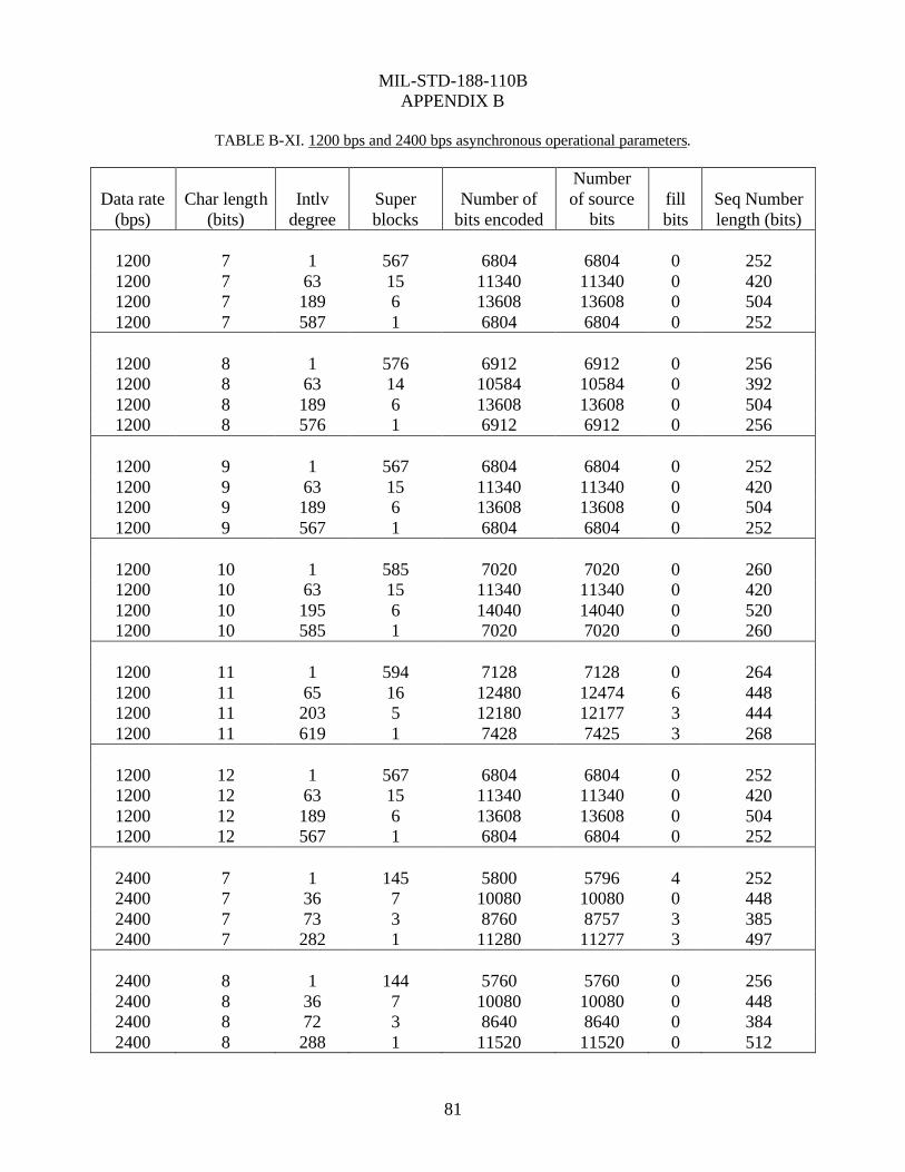
MIL-STD-188-110B
APPENDIX B
81
TABLE B-XI. 1200 bps and 2400 bps asynchronous operational parameters.
Data rate (bps)
Char length (bits)
Intlv degree
Super blocks
Number of bits encoded
Number of source
bits fill bits
Seq Number length (bits)
1200 7 1 567 6804 6804 0 252 1200 7 63 15 11340 11340 0 420 1200 7 189 6 13608 13608 0 504 1200 7 587 1 6804 6804 0 252
1200 8 1 576 6912 6912 0 256 1200 8 63 14 10584 10584 0 392 1200 8 189 6 13608 13608 0 504 1200 8 576 1 6912 6912 0 256
1200 9 1 567 6804 6804 0 252 1200 9 63 15 11340 11340 0 420 1200 9 189 6 13608 13608 0 504 1200 9 567 1 6804 6804 0 252
1200 10 1 585 7020 7020 0 260 1200 10 63 15 11340 11340 0 420 1200 10 195 6 14040 14040 0 520 1200 10 585 1 7020 7020 0 260
1200 11 1 594 7128 7128 0 264 1200 11 65 16 12480 12474 6 448 1200 11 203 5 12180 12177 3 444 1200 11 619 1 7428 7425 3 268
1200 12 1 567 6804 6804 0 252 1200 12 63 15 11340 11340 0 420 1200 12 189 6 13608 13608 0 504 1200 12 567 1 6804 6804 0 252
2400 7 1 145 5800 5796 4 252 2400 7 36 7 10080 10080 0 448 2400 7 73 3 8760 8757 3 385 2400 7 282 1 11280 11277 3 497
2400 8 1 144 5760 5760 0 256 2400 8 36 7 10080 10080 0 448 2400 8 72 3 8640 8640 0 384 2400 8 288 1 11520 11520 0 512

MIL-STD-188-110B
APPENDIX B
82
Data rate (bps)
Char length (bits)
Intlv degree
Super blocks
Number of bits encoded
Number of source
bits fill bits
Seq Number length (bits)
2400 9 1 144 5760 5760 0 256 2400 9 36 7 10080 10080 0 448 2400 9 72 3 8640 8640 0 384 2400 9 288 1 11520 11520 0 512
2400 10 1 144 5760 5760 0 256 2400 10 36 7 10080 10080 0 448 2400 10 72 3 8640 8640 0 384 2400 10 288 1 11520 11520 0 512
2400 11 1 151 6040 6039 1 267 2400 11 33 9 11880 11880 0 528 2400 11 71 3 8520 8514 6 370 2400 11 297 1 11880 11880 0 528
2400 12 1 144 5760 5760 0 256 2400 12 36 7 10080 10080 0 448 2400 12 72 3 8640 8640 0 384 2400 12 288 1 11520 11520 0 512

MIL-STD-188-110B
APPENDIX B
83
TABLE B-XII. Probability of bit error vs signal-to-noise ratio.
Probability of bit error
Signal-to-noise ratio (dB in 3-kHz bandwidth) 2400 bps 1200 bps
5 8.6 E-2 6.4 E-2 10 3.5 E-2 4.4 E-3 15 1.0 E-2 3.4E-4 20 1.0 E-3 9.0 E-6 30 1.8 E-4 2.7 E-6 Probability of bit error
300 bps 75 bps 0 1.8 E-2 4.4 E-4 2 6.4 E-3 5.0 E-5 4 1.0 E-3 1.0 E-6 6 5.0 E-5 1.0 E-6 8 1.5 E-6 1.0 E-6
NOTE: Two independent equal average power Rayleigh fading paths, with 2 Hz fading
bandwidth and 2 ms multipath spread.

MIL-STD-188-110B
APPENDIX B
84
FECCODING
INTERLEAVEMATRIX #1
INTERLEAVEMATRIX #2
DATAFETCH
BLOCK SYNC
PREAMBLESYNC
TONEMODULATOR
(2400)
UNKNOWNDATA
FILL OR EOMSEQUENCE
(3360)
(107)
PREAMBLE CONTROL
}
COMPOSITE39-TONE
+ DOPPLERSIGNAL
FIGURE B-1. Transmit direction functional diagram .

MIL-STD-188-110B
APPENDIX B
85
D31D30 D29D28 D27 D26D25D24 D7 D6 D5 D4 D3 D2 D1 D0 SYMBOL0D39D38 D37D36 D35 D34D33D32D15D14 D13D12 D11 D10 D9 D8 SYMBOL1D47D46 D45D44 D43 D42D41D40D22D21 D20D19 D18 D17D16D15SYMBOL2P51P50 P49 P48 P35 P34 P33P32 P18P17 P16 P15 P3 P2 P1 P0 SYMBOL3P55P54 P53 P52 P39 P38 P37P36 P23P22 P21 P20 P7 P6 P5 P4 SYMBOL4P59P58 P57 P56 P43 P42 P41P40 P27P26 P25 P24 P11 P10 P9 P8 SYMBOL5P63P62 P61 P60 P47 P46 P45P44 P31P30 P29 P28 P15 P14 P13P12SYMBOL6
COD EWOR D1
COD EWOR D4
COD EWOR D3
COD EWOR D2
COD EWOR D1
PARITYSYMBOL
S
D47 D46 D45 D44 … D4 D3 D2 D1 D0 P3 P2 P1 P0 D19D18D17D16D11D10D9 D8 D3 D2 D1 D0
IN P UT D ATASTR EAM FE C
E NCODER
FIRS TBIT IN FIRS T
BIT OU T
INTE RLEAV E R P63 P62 … P12 … D16 D39 … D8 D31D30D29D28D27 D26D25 D24 D7 D6 D5 D4 D3 D2 D1 D0
DA T AS YMB OLS
FIGU RE B-2. D ata fl ow thro u g h e nco d e r a n d i nterle a ver f or a n interle a v er c o ntainin g a n e v e n numb e r of c o d ew ord s.

MIL-STD-188-110B
APPENDIX B
86
D27 D26 D25 D24 D7 D6 D5 D4 D3 D2 D1 D0 SYMBOL 0D35 D34 D33 D32 D15 D14 D13 D12 D11 D10 D9 D8 SYMBOL 1D43 D42 D41 D40 D23 D22 D21 D20 D19 D18 D17 D16 SYMBOL 2P35 P34 P33 P32 P19 P18 P17 P16 P3 P2 P1 P0 SYMBOL 3P39 P38 P37 P36 P23 P22 P21 P20 P7 P6 P5 P4 SYMBOL 4P43 P42 P41 P40 P27 P26 P25 P24 P11 P10 P9 P8 SYMBOL 5P47 P46 P45 P44 P31 P30 P29 P28 P15 P14 P13 P12 SYMBOL 6
CODEWORD 1
CODEWORD 3 CODEWORD 2 CODEWORD 1
PARITYSYMBOLS
D35 D34 D33 D32 … D4 D3 D2 D1 D0 P3 P2 P1 P0 D19 D18 D17 D16D11 D10 D9 D8 D3 D2 D1 D0
INPUT DATA STREAM
FECENCODER
FIRSTBIT IN FIRST
BIT OUT
INTERLEAVER P47 P46 … P13 P12 … D16 D31 … D12 D11 D10 D49 D8 D27 D26D25 D24 D7 D6 D5 D4 D3 D2 D1 D0
DATASYMBOLS
FIGURE B-3. Data flow through encoder and interleaver for an interleaver containing an odd number of code words.

MIL-STD-188-110B
APPENDIX B
87
3MODULATED
TONES
BLOCKSYNC
4UNMODULATED
TONES
DATA SUPERBLOCKS(S)
1-576 BLOCKS8064 TO 31752 BITS
BLOCKSYNC
FILLOR
DATADATA ASYNC
EOM
315 ms 180 ms 22.5 ms
517.5 ms
PREAMBLE40 REFERENCE TONES
FIGURE B-4. Transmit sequence of events .

MIL-STD-188-110B
APPENDIX B
88
FIGURE B-5. Framing sequence feedback shift register generator

MIL-STD-188-110B
APPENDIX C
89
CONTENTS
PARAGRAPH PAGE C.1 GENERAL 91 C.1.1 Scope 91 C.1.2 Applicability 91 C.2 APPLICABLE DOCUMENTS 91 C.3 DEFINITIONS 91 C.4 GENERAL REQUIREMENTS 91 C.5 DETAILED REQUIREMENTS 91 C.5.1 Modulation 91 C.5.2 Frame structure 101 C.5.3 Coding and interleaving 106 C.5.4 Operational features and message protocols 109 C.6 PERFORMANCE 112 C.6.1 BER performance 112 C.6.2 Acquisition performance 113 C.6.3 Doppler shift test 113 C.6.4 Doppler sweep performance 113 C.7 ASSOCIATED COMMUNICATIONS EQUIPMENT 113 LIST OF FIGURES C-1 8PSK signal constellation and symbol mapping 93 C-2 16QAM signaling constellation 96 C-3 32QAM signaling constellation 97 C-4 64QAM signaling constellation 98 C-5 Scrambling sequence generator illustrating scrambling
generator for 8PSK symbols 100 C-6 Frame sequence for all waveforms 101 C-7 Constraint length 7, rate 1/2 convolutional encoder 107

MIL-STD-188-110B
APPENDIX C
90
CONTENTS LIST OF TABLES C-I 8PSK symbol mapping 93 C-II Modulation used to obtain each data rate 94 C-III Transcoding for 3200 bps 94 C-IV Transcoding for 3200 bps 95 C-V In-phase and Quadrature components of each 16QAM symbol 96 C-VI In-phase and Quadrature components of each 32QAM symbol 97 C-VII In-phase and Quadrature components of each 64QAM symbol 99 C-VIII D0, D1, D2 8PSK symbol values as a function of data rate
and interleaver length 103 C-IX Bit patterns for specifying data rate and interleaver length 103 C-X S0, S1, S2, S3, S4, S5 (sign) values as a function of data rate
and interleaver setting 105 C-XI S6, S7, S8 (sign) values as a function of mini-probe set 105 C-XII Input data block size in bits as a function of data rate
and interleaver length 106 C-XIII Interleaver size in bits as a function of data rate and interleaver
length 108 C-XIV Interleaver increment value as a function of data rate and interleaver length 109 C-XV High data rate mode performance requirements 112

MIL-STD-188-110B
APPENDIX C
91
HF Data Modem Waveforms for Data Rates Above 2400 bps
C.1 GENERAL C.1.1 Scope. This appendix describes the HF data modem waveforms for data rates above 2400 bps. C.1.2 Applicability. This appendix is a nonmandatory part of MIL-STD-188-110B; however, when using HF data modem waveforms for data rates above 2400 bps, they shall be implemented in accordance with this appendix. C.2 APPLICABLE DOCUMENTS This section is not applicable to this appendix. C.3 DEFINITIONS See section 3. C.4 GENERAL REQUIREMENTS This appendix presents a modem waveform and coding specification for data rates of 3200, 4800, 6400, 8000 and 9600 bps. Uncoded operation at 12800 bps is a DO. The single-tone waveforms specified in this appendix use modulation techniques of greater complexity and data blocks larger than those found in section 5.3.2 of this standard in order to achieve the efficiencies necessary to obtain the required data rates. A block interleaver is used to obtain 6 interleaving lengths ranging from 0.12 s to 8.64 s. A single coding option, a constraint length 7, rate 1/2 convolutional code, punctured to rate 3/4, is used for all data rates. The full-tail-biting approach is used to produce block codes from this convolutional code that are the same length as the interleaver. Since the minimum interleaver length spans a single data frame, there is no option of zero interleaving, since the time delays would not be reduced. Both the data rate and interleaver settings are explicitly transmitted as a part of the waveform, both as part of the initial preamble and then periodically as both a reinserted preamble and in the periodic known symbol blocks. This “autobaud” feature is critical in developing an efficient (ARQ) protocol for high frequency (HF) channels. The receive modem is required to be able to deduce the data rate and interleaver setting both from the preamble or from the subsequent data portion of the waveform. C.5 DETAILED REQUIREMENTS C.5.1 Modulation. The symbol rate for all symbols shall be 2400 symbols-per-second, which shall be accurate to a minimum of ±0.24 (10 ppm) symbols-per-second when the transmit data clock is generated by the modem and not provided by the data terminal equipment (DTE). Phase-shift keying (PSK)

MIL-STD-188-110B
APPENDIX C
92
and quadrature amplitude modulation (QAM) modulation techniques shall be used. The sub-carrier (or pair of quadrature sub-carriers in the case of QAM) shall be centered at 1800 Hz accurate to a minimum of 0.018 Hz (10 ppm). The phase of the Quadrature sub-carrier relative to the In-phase carrier shall be 90 degrees. The correct relationship can be achieved by making the In-phase sub-carrier cos(1800 Hz) and the Quadrature sub-carrier -sin(1800 Hz). The power spectral density of the modulator output signal should be constrained to be at least 20 dB below the signal level measured at 1800 Hz, when tested outside of the band from 200 Hz to 3400 Hz. The filter employed shall result in a ripple of no more than ±2 dB in the range from 800 Hz to 2800 Hz. C.5.1.1 Known symbols. For all known symbols, the modulation used shall be PSK, with the symbol mapping shown in table C-I and figure C-1. No scrambling shall be applied to the known symbols.

MIL-STD-188-110B
APPENDIX C
93
TABLE C-I. 8PSK symbol mapping.
Symbol Number
Phase In-Phase Quadrature
0 0 1.000000 0.000000 1 π/4 0.707107 0.707107 2 π/2 0.000000 1.000000 3 3π/4 -0.707107 0.707107 4 π -1.000000 0.000000 5 5π/4 -0.707107 -0.707107 6 3π/2 0.0000000 -1.000000 7 7π/4 0.707107 -0.707107
Note that the complex symbol values = exp[jnπ/4] where n is the symbol number.
FIGURE C-1. 8PSK signal constellation and symbol mapping.
C.5.1.2 Data symbols. For data symbols, the modulation used shall depend upon the data rate. Table C-II specifies the modulation that shall be used with each data rate.

MIL-STD-188-110B
APPENDIX C
94
TABLE C-II. Modulation used to obtain each data rate.
Data Rate (bps)
Modulation
3200 QPSK 4800 8PSK 6400 16QAM 8000 32QAM 9600 64QAM 12800 64QAM
The 3200 bps quadrature phase-shift keying (QPSK) constellation is scrambled to appear, on-air, as an 8PSK constellation. Both the 16QAM and 32QAM constellations use multiple PSK rings to maintain good peak-to-average ratios, and the 64QAM constellation is a variation of the standard square QAM constellation, which has been modified to improve the peak-to-average ratio. C.5.1.2.1 PSK data symbols. For the PSK constellations, a distinction is made between the data bits and the symbol number for the purposes of scrambling the QPSK modulation to appear as 8PSK, on-air. Scrambling is applied as a modulo 8 addition of a scrambling sequence to the 8PSK symbol number. Transcoding is an operation which links a symbol to be transmitted to a group of data bits. C.5.1.2.1.1 QPSK symbol mapping. For the 3200 bps user data rate, transcoding shall be achieved by linking one of the symbols specified in table C-I to a set of two consecutive data bits (dibit) as shown in table C-III. In this table, the leftmost bit of the dibit shall be the older bit; i.e., fetched from the interleaver before the rightmost bit.
TABLE C-III. Transcoding for 3200 bps.
Dibit Symbol 00 0 01 2 11 4 10 6
C.5.1.2.1.2 8PSK symbol mapping. For the 4800 bps user data rate, transcoding shall be achieved by linking one symbol to a set of three consecutive data bits (tribit) as shown in table C-IV. In this table, the leftmost bit of the tribit shall be the oldest bit; i.e., fetched from the interleaver before the other two, and the rightmost bit is the most recent bit.

MIL-STD-188-110B
APPENDIX C
95
TABLE C-IV. Transcoding for 4800 bps.
Tribit Symbol 000 1 001 0 010 2 011 3 100 6 101 7 110 5 111 4
C.5.1.2.2 QAM data symbols. For the QAM constellations, no distinction is made between the number formed directly from the data bits and the symbol number. Each set of 4 bits (16QAM), 5 bits (32QAM) or 6 bits (64QAM) is mapped directly to a QAM symbol. For example, the four bit grouping 0111 would map to symbol 7 in the 16QAM constellation while the 6 bit grouping 100011 would map to symbol 35 in the 64QAM constellation. Again, in each case the leftmost bit shall be the oldest bit, i.e. fetched from the interleaver before the other bits, and the rightmost bit is the most recent bit. The mapping of bits to symbols for the QAM constellations has been selected to minimize the number of bit errors incurred when errors involve adjacent signaling points in the constellation. C.5.1.2.2.1 The 16 QAM constellation. The constellation points which shall be used for 16QAM are shown in figure C-2 and specified in terms of their In-phase and Quadrature components in table C-V. As can be seen in the figure, the 16 QAM constellation is comprised of two PSK rings: 4 PSK inner and 12 PSK outer

MIL-STD-188-110B
APPENDIX C
96
16 Point Constellation
-1
1
-1 1
FIGURE C-2. 16QAM Signaling Constellation.
TABLE C-V. In-phase and Quadrature components of each 16QAM symbol.
Symbol Number
In-Phase Quadrature
0 0.866025 0.500000 1 0.500000 0.866025 2 1.000000 0.000000 3 0.258819 0.258819 4 -0.500000 0.866025 5 0.000000 1.000000 6 -0.866025 0.500000 7 -0.258819 0.258819 8 0.500000 -0.866025 9 0.000000 -1.000000 10 0.866025 -0.500000 11 0.258819 -0.258819 12 -0.866025 -0.500000 13 -0.500000 -0.866025 14 -1.000000 0.000000 15 -0.258819 -0.258819

MIL-STD-188-110B
APPENDIX C
97
C.5.1.2.2.2 The 32 QAM constellation. The constellation points which shall be used for 32QAM are shown in figure C-3 and specified in terms of their In-phase and Quadrature components in table C-VI. This constellation contains an outer ring of 16 symbols and an inner square of 16 symbols.
FIGURE C-3. 32QAM signaling constellation.
TABLE C-VI. In-phase and Quadrature components of each 32QAM symbol.
Symbol Number
In-Phase Quadrature Symbol Number
In-Phase Quadrature
0 0.866380 0.499386 16 0.866380 -0.499386 1 0.984849 0.173415 17 0.984849 -0.173415 2 0.499386 0.866380 18 0.499386 -0.866380 3 0.173415 0.984849 19 0.173415 -0.984849 4 0.520246 0.520246 20 0.520246 -0.520246 5 0.520246 0.173415 21 0.520246 -0.173415 6 0.173415 0.520246 22 0.173415 -0.520246 7 0.173415 0.173415 23 0.173415 -0.173415 8 -0.866380 0.499386 24 -0.866380 -0.499386 9 -0.984849 0.173415 25 -0.984849 -0.173415 10 -0.499386 0.866380 26 -0.499386 -0.866380 11 -0.173415 0.984849 27 -0.173415 -0.984849 12 -0.520246 0.520246 28 -0.520246 -0.520246 13 -0.520246 0.173415 29 -0.520246 -0.173415 14 -0.173415 0.520246 30 -0.173415 -0.520246 15 -0.173415 0.173415 31 -0.173415 -0.173415

MIL-STD-188-110B
APPENDIX C
98

MIL-STD-188-110B
APPENDIX C
99
C.5.1.2.2.3 The 64QAM constellation. The constellation points which shall be used for the 64QAM modulation are shown in figure C-4 and specified in terms of their In-phase and Quadrature components in table C-VII. This constellation is a variation on the standard 8 x 8 square constellation, which achieves better peak-to-average without sacrificing the very good pseudo-Gray code properties of the square constellation.
64 Point Constellation
-1
1
-1 1
FIGURE C-4. 64QAM signaling constellation.

MIL-STD-188-110B
APPENDIX C
100
TABLE C-VII. In-phase and Quadrature components of each 64QAM symbol.
Symbol Number
In-Phase Quadrature Symbol Number
In-Phase Quadrature
0 1.000000 0.000000 32 0.000000 1.000000 1 0.822878 0.568218 33 -0.822878 0.568218 2 0.821137 0.152996 34 -0.821137 0.152996 3 0.932897 0.360142 35 -0.932897 0.360142 4 0.000000 -1.000000 36 -1.000000 0.000000 5 0.822878 -0.568218 37 -0.822878 -0.568218 6 0.821137 -0.152996 38 -0.821137 -0.152996 7 0.932897 -0.360142 39 -0.932897 -0.360142 8 0.568218 0.822878 40 -0.568218 0.822878 9 0.588429 0.588429 41 -0.588429 0.588429 10 0.588429 0.117686 42 -0.588429 0.117686 11 0.588429 0.353057 43 -0.588429 0.353057 12 0.568218 -0.822878 44 -0.568218 -0.822878 13 0.588429 -0.588429 45 -0.588429 -0.588429 14 0.588429 -0.117686 46 -0.588429 -0.117686 15 0.588429 -0.353057 47 -0.588429 -0.353057 16 0.152996 0.821137 48 -0.152996 0.821137 17 0.117686 0.588429 49 -0.117686 0.588429 18 0.117686 0.117686 50 -0.117686 0.117686 19 0.117686 0.353057 51 -0.117686 0.353057 20 0.152996 -0.821137 52 -0.152996 -0.821137 21 0.117686 -0.588429 53 -0.117686 -0.588429 22 0.117686 -0.117686 54 -0.117686 -0.117686 23 0.117686 -0.353057 55 -0.117686 -0.353057 24 0.360142 0.932897 56 -0.360142 0.932897 25 0.353057 0.588429 57 -0.353057 0.588429 26 0.353057 0.117686 58 -0.353057 0.117686 27 0.353057 0.353057 59 -0.353057 0.353057 28 0.360142 -0.932897 60 -0.360142 -0.932897 29 0.353057 -0.588429 61 -0.353057 -0.588429 30 0.353057 -0.117686 62 -0.353057 -0.117686 31 0.353057 -0.353057 63 -0.353057 -0.353057
C.5.1.3 Data scrambling. Data symbols for the 8PSK symbol constellation (3200 bps, 4800 bps) shall be scrambled by modulo 8 addition with a scrambling sequence. The data symbols for the 16QAM, 32QAM, and 64QAM constellations shall be scrambled by using an exclusive or (XOR) operation. Sequentially, the data bits forming each symbol (4 for 16QAM, 5 for 32QAM, and 6 for 64QAM) shall be XOR’d with an equal number of bits from the scrambling sequence. In all cases, the scrambling sequence generator polynomial shall be x9 +x4 +1 and the generator shall be

MIL-STD-188-110B
APPENDIX C
101
initialized to 1 at the start of each data frame. A block diagram of the scrambling sequence generator is shown in figure C-5.
FIGURE C-5. Scrambling sequence generator illustrating scrambling generator for 8PSK symbols.
For 8PSK symbols (3200 bps and 4800 bps), the scrambling shall be carried out taking the modulo 8 sum of the numerical value of the binary triplet consisting of the last (rightmost) three bits in the shift register, and the symbol number (transcoded value). For example, if the last three bits in the scrambling sequence shift register were 010 which has a numerical value equal 2, and the symbol number before scrambling was 6, symbol 0 would be transmitted since: (6+2) Modulo 8 = 0. For 16QAM symbols, scrambling shall be carried out by XORing the 4 bit number consisting of the last (rightmost) four bits in the shift register with the symbol number. For example, if the last 4 bits in the scrambling sequence shift register were 0101 and the 16QAM symbol number before scrambling was 3 (i.e. 0011), symbol 6 (0110) would be transmitted. For 32QAM symbols, scrambling shall be carried out by XORing the 5 bit number formed by the last (rightmost) five bits in the shift register with the symbol number. For 64QAM symbols, scrambling shall be carried out by XORing the 6 bit number formed by the last (rightmost) six bits in the shift register with the symbol number. After each data symbol is scrambled, the generator shall be iterated (shifted) the required number of times to produce all new bits for use in scrambling the next symbol (i.e., 3 iterations for 8PSK, 4 iterations for 16QAM, 5 iterations for 32QAM and 6 iterations for 64QAM). Since the generator is iterated after the bits are use, the first data symbol of every data frame shall, therefore, be scrambled by the appropriate number of bits from the initialization value of 00000001.

MIL-STD-188-110B
APPENDIX C
102
The length of the scrambling sequence is 511 bits. For a 256 symbol data block with 6 bits per symbol, this means that the scrambling sequence will be repeated just slightly more than 3 times, although in terms of symbols, there will be no repetition. C.5.2 Frame structure. The frame structure that shall be used for the waveforms specified in this appendix is shown in figure C-6. An initial 287 symbol preamble is followed by 72 frames of alternating data and known symbols. Each data frame shall consist of a data block consisting of 256 data symbols, followed by a mini-probe consisting of 31 symbols of known data. After 72 data frames, a 72 symbol subset of the initial preamble is reinserted to facilitate late acquisition, Doppler shift removal, and sync adjustment. It should be noted that the total length of known data in this segment is actually 103 symbols: the 72 reinserted preamble symbols plus the preceding 31 symbol mini-probe segment which follows the last 256 symbol data block.
287
FIGURE C-6. Frame structure for all waveforms.
C.5.2.1 Synchronization and reinserted preambles. The synchronization preamble is used for rapid initial synchronization. The reinserted preamble is used to facilitate acquisition of an ongoing transmission (acquisition on data). C.5.2.1.1 Synchronization preamble. The synchronization preamble shall consist of two parts. The first part shall consist of at least N blocks of 184 8-PSK symbols to be used exclusively for radio and modem AGC. The value of N shall be configurable to range from values of 0 to 7 (for N=0 this first section is not sent at all). These 184 symbols shall be formed by taking the complex conjugate of the first 184 symbols of the sequence specified below for the second section.

MIL-STD-188-110B
APPENDIX C
103
The second section shall consist of 287 symbols. The first 184 symbols are intended exclusively for synchronization and Doppler offset removal purposes while the final 103 symbols, which are common with the reinserted preamble, also carry information regarding the data rate and interleaver settings. Expressed as a sequence of 8PSK symbols, using the symbol numbers given in table C-I the synchronization preamble shall be:
1, 5, 1, 3, 6, 1, 3, 1, 1, 6, 3, 7, 7, 3, 5, 4, 3, 6, 6, 4, 5, 4, 0, 2, 2, 2, 6, 0, 7, 5, 7, 4, 0, 7, 5, 7, 1, 6, 1, 0, 5, 2, 2, 6, 2, 3, 6, 0, 0, 5, 1, 4, 2, 2, 2, 3, 4, 0, 6, 2, 7, 4, 3, 3, 7, 2, 0, 2, 6, 4, 4, 1, 7, 6, 2, 0, 6, 2, 3, 6, 7, 4, 3, 6, 1, 3, 7, 4, 6, 5, 7, 2, 0, 1, 1, 1, 4, 4, 0, 0, 5, 7, 7, 4, 7, 3, 5, 4, 1, 6, 5, 6, 6, 4, 6, 3, 4, 3, 0, 7, 1, 3, 4, 7, 0, 1, 4, 3, 3, 3, 5, 1, 1, 1, 4, 6, 1, 0, 6, 0, 1, 3, 1, 4, 1, 7, 7, 6, 3, 0, 0, 7, 2, 7, 2, 0, 2, 6, 1, 1, 1, 2, 7, 7, 5, 3, 3, 6, 0, 5, 3, 3, 1, 0, 7, 1, 1, 0, 3, 0, 4, 0, 7, 3,
0, 0, 0, 0, 0, 2, 4, 6, 0, 4, 0, 4, 0, 6, 4, 2, 0, 0, 0, 0, 0, 2, 4, 6, 0, 4, 0, 4, 0, 6, 4, 2, ( D0, D0, D0, D0, D0, D0, D0, D0, D0, D0, D0, D0, D0 + 0, 4, 0, 4, 0, 0, 4, 4, 0, 0, 0, 0, 0) Modulo 8 ( D1, D1, D1, D1, D1, D1, D1, D1, D1, D1, D1, D1, D1 + 0, 4, 0, 4, 0, 0, 4, 4, 0, 0, 0, 0, 0) Modulo 8 ( D2, D2, D2, D2, D2, D2, D2, D2, D2, D2, D2, D2, D2 + 0, 4, 0, 4, 0, 0, 4, 4, 0, 0, 0, 0, 0) Modulo 8 6, 4, 4, 4, 4, 4, 6, 0, 2, 4, 0, 4, 0, 4, 2, 0, 6, 4, 4, 4, 4, 4, 6, 0, 2, 4, 0, 4, 0, 4, 2, 0 where the data symbols D0, D1, and D2 take one of 30 sets of values chosen from table C-VIII to indicate the data rate and interleaver settings. The Modulo operations are meant to signify that each of the D values are used to shift the phase of a length 13 bit Barker code (0101001100000) by performing modulo 8 addition of the D value with each of the Barker code 13 phase values (0 or 4). This operation can encode 6 bits of information using QPSK modulation of the 13 bit (chip) Barker codes. Since the three Barker code sequences only occupy 39 symbols, the 31 symbol mini-probes are lengthened to 32 symbols each to provide the additional 2 symbols required to pad the three 13 symbol Barker codes up to a total of 41 symbols.

MIL-STD-188-110B
APPENDIX C
104
TABLE C-VIII. D0, D1, D2 8 PSK symbol values as a function of data rate and interleaver length.
Interleaver Length in Frames (256 Symbol Data Blocks) Data Rate
(bps) 1 3 9 18 36 72
3200 0,0,4 0,2,6 0,2,4 2,0,6 2,0,4 2,2,6 4800 0,6,2 0,4,0 0,4,2 2,6,0 2,6,2 2,4,0 6400 0,6,4 0,4,6 0,4,4 2,6,6 2,6,4 2,4,6 8000 6,0,2 6,2,0 6,2,2 4,0,0 4,0,2 4,2,0 9600 6,0,4 6,2,6 6,2,4 4,0,6 4,0,4 4,2,6 12800 6,6,2* reserved reserved reserved reserved reserved
* For 12800 bps 1 frame interleaver shall be interpreted as no interleaving The mapping chosen to create table C-VIII uses 3 bits each to specify the data rate and interleaver length. The 3 data rate bits are the 3 most significant bits (MSB) of 3 dibit symbols and the interleaver length bits are the least significant bits (LSB). The phase of the Barker code is determined from the 3 resulting dibit words using TABLE C-III, the dibit transcoding table. The 3 bit data rate and interleaver length mappings are shown in table C-IX. Note that the transcoding has the effect of placing the 3 interleaver length bits in quadrature with the 3 data rate bits.
TABLE C-IX. Bit patterns for specifying data rate and interleaver length.
Data Rate 3 Bit Mapping Interleaver Length 3 Bit Mapping Name reserved 000 illegal: see C.5.2.1.2 000 3200 001 1 Frame 001 Ultra Short (US) 4800 010 3 Frames 010 Very Short (VS) 6400 011 9 Frames 011 Short (S) 8000 100 18 Frames 100 Medium (M) 9600 101 36 Frames 101 Long (L) 12800 110 72 Frames 110 Very Long (VL) reserved 111 illegal: see C.5.2.1.2 111
Because the Barker code is unbalanced in terms of the number of 0s and 1s, the 000 or 111 patterns exhibit a net imbalance in each quadrature component of the 39 symbols that is 12 to 27. These two patterns are reserved for future standardization of high data rate modes that employ constellations more dense than those specified in C.5.1. The other 3-bit patterns are more balanced (17 to 22) and are used for the more robust constellations. C.5.2.1.2 Reinserted preamble. The reinserted preamble shall be identical to the final 72 symbols of the synchronization preamble. In fact, the final 103 symbols are common between the synchronization preamble and the contiguous block consisting of the reinserted preamble and the mini-probe which

MIL-STD-188-110B
APPENDIX C
105
immediately precedes it. The 103 symbols of known data (including the 31 mini-probe symbols of the preceding data frame) are thus: 0, 0, 0, 0, 0, 2, 4, 6, 0, 4, 0, 4, 0, 6, 4, 2, 0, 0, 0, 0, 0, 2, 4, 6, 0, 4, 0, 4, 0, 6, 4, 2, ( D0, D0, D0, D0, D0, D0, D0, D0, D0, D0, D0, D0, D0 + 0, 4, 0, 4, 0, 0, 4, 4, 0, 0, 0, 0, 0) Modulo 8 ( D1, D1, D1, D1, D1, D1, D1, D1, D1, D1, D1, D1, D1 + 0, 4, 0, 4, 0, 0, 4, 4, 0, 0, 0, 0, 0) Modulo 8 ( D2, D2, D2, D2, D2, D2, D2, D2, D2, D2, D2, D2, D2 + 0, 4, 0, 4, 0, 0, 4, 4, 0, 0, 0, 0, 0) Modulo 8 6, 4, 4, 4, 4, 4, 6, 0, 2, 4, 0, 4, 0, 4, 2, 0, 6, 4, 4, 4, 4, 4, 6, 0, 2, 4, 0, 4, 0, 4, 2, 0; where the data symbols D0, D1, and D2 again take one of 30 sets of values chosen from table C-VIII to indicate the data rate and interleaver settings as described in the Synchronization Preamble section above. The first 31 of these symbols are the immediately preceding mini-probe, which follows the last of the 72 data blocks. Note that the 3 Bit Mappings for Interleaver Length of 000 or 111 may result in an S0 to S8 pattern that could be confused with the fixed (- - - - - - - +) mini probe pattern. For this reason, these mappings are referred to as “illegal” in Table C-IX. C.5.2.2 Mini-probes. Mini-probes 31 symbols in length shall be inserted following every 256 symbol data block and at the end of each preamble (where they are considered to be part of the preamble). Using the 8PSK symbol mapping, each mini-probe shall be based on the repeated Frank-Heimiller sequence. The sequence that shall be used, specified in terms of the 8PSK symbol numbers, is given by: 0, 0, 0, 0, 0, 2, 4, 6, 0, 4, 0, 4, 0, 6, 4, 2, 0, 0, 0, 0, 0, 2, 4, 6, 0, 4, 0, 4, 0, 6, 4. This mini-probe will be designated ‘+’. The phase inverted version of this is: 4, 4, 4, 4, 4, 6, 0, 2, 4, 0, 4, 0, 4, 2, 0, 6, 4, 4, 4, 4, 4, 6, 0, 2, 4, 0, 4, 0, 4, 2, 0 and mini-probes using this sequence will be designated ‘-’, as the phase of each symbol has been rotated 180 degrees from the ‘+’. There are a total of 73 mini-probes for each set of 72 data blocks. For convenience, each mini-probe will be sequentially numbered, with mini-probe 0 being defined as the last 31 symbols of the preceding (reinserted) preamble, mini-probe number 1 following the first data block after a (reinserted) preamble. Mini-probe 72 follows the 72nd data block, and is also the first 31 symbols of the next 103 symbol reinserted preamble. Mini-probes 0 and 72 have been defined as part of the reinsertion preamble to have the signs - and + respectively. The data rate and

MIL-STD-188-110B
APPENDIX C
106
interleaver length information encoded into the synchronization and reinserted preambles shall also be encoded into mini-probes 1 through 72. These 72 mini-probes are grouped into four sets of 18 consecutive mini-probes (1 to 18, 19 to 36, 37 to 54, and 55 to 72). Note that the 256 symbol data block that immediately follows the 18th mini-probe, in each of the first three sets, is also the 1st data block of an interleaver block with frame lengths of 1, 3, 9, and 18. The length 36 interleaver block begins after the second set, and a reinserted preamble begins after the fourth set. This structure permits data to begin to be demodulated as soon as the interleaver boundary becomes known. Each 18 mini-probe sequence shall consists of seven – signs, a + sign, followed by six sign values that are dependent on the data rate and interleaver length, three sign values that specify which of the four sets of 18 mini-probes it is, and then finally a + sign. For the fourth set, this final + sign (mini-probe 72) is also the initial mini-probe of the next reinserted preamble (which uses the + phase). Pictorially, this length 18 sequence is: - - - - - - - + S0 S1 S2 S3 S4 S5 S6 S7 S8 +, where the first six Si sign values are defined in table C-X. Note that these 6 bit patterns ( + is a 0 ) correspond to the concatenation of the 3 bit mappings from table C-IX for the data rate (S0 S1 S2) and the interleaver length (S3 S4 S 5). The final three Si sign values which specify the mini-probe set (count) are defined in table C-XI.
TABLE C-X. S0, S1, S2, S3, S4, S5 (sign) values as a function of data rate and interleaver setting.
Interleaver Length in Frames (256 Symbol Data Blocks) Data Rate (bps) 1 3 9 18 36 72 3200 + + - + + - + + - + - + + + - + - - + + - - + + + + - - + - + + - - - +
4800 + - + + + - + - + + - + + - + + - - + - + - + + + - + - + - + - + - - +
6400 + - - + + - + - - + - + + - - + - - + - - - + + + - - - + - + - - - - +
8000 - + + + + - - + + + - + - + + + - - - + + - + + - + + - + - - + + - - +
9600 - + - + + - - + - + - + - + - + - - - + - - + + - + - - + - - + - - - +
12800 - - + + + - N/A N/A N/A N/A N/A
TABLE C-XI. S6, S7, S8 (sign) values as a function of mini-probe set.
Mini-probe set 1 to 18 19 to 36 37 to 54 55 to 72
+ + - + - + + - - - + +
The 1st eight mini-probes in each set (- - - - - - - +) uniquely locate the starting point for the following nine Si values. This is possible since the Si sequences used contain at most runs of four + or - phases. This makes it impossible for a sequence of 7 mini-probes with the same phase followed by one with a phase reversal to occur anywhere else except at the beginning of one of the 18 mini-probe sequences. Once this fixed 8 mini-probe pattern is located, the 0 or 180 degree phase ambiguity is also resolved so that the following 9 mini-probes can be properly

MIL-STD-188-110B
APPENDIX C
107
matched to the data rate, interleaver length, and mini-probe set count. The entire mini-probe sequence shall therefore be as follows: [rp] - - - - - - - + S0 S1 S2 S3 S4 S5 S6 S7 S8 + - - - - - - - + S0 S1 S2 S3 S4 S5 S6 S7 S8 +
- - - - - - - + S0 S1 S2 S3 S4 S5 S6 S7 S8 + - - - - - - - + S0 S1 S2 S3 S4 S5 S6 S7 S8 [rp]
where the [rp] represents the 103 reinserted preamble symbols (includes mini-probes 72 and 0). C.5.3 Coding and interleaving. The interleaver used shall be a block interleaver. Each block of input data shall also be encoded using a block encoding technique with a code block size equal to the size of the block interleaver. Thus, the input data bits will be sent as successive blocks of bits that span the duration of the interleaver length selected. Table C-XII shows the number of input data bits per block as function of both data rate and interleaver length. Note that an “input data block” should not be confused with the 256 symbol data block that is part of a data frame in the waveform format. The bits from an input data block will be mapped through the coding and interleaving to the number of data frames, and thus 256 symbol data blocks, that define the interleaver length.
TABLE C-XII. Input data block size in bits as a function of data rate and interleaver length
Interleaver Length in Frames 1 3 9 18 36 72
Data Rate (bps) Number of Input Data Bits per Block 3200 384 1152 3456 6912 13824 27648 4800 576 1728 5184 10368 20736 41472 6400 768 2304 6912 13824 27648 55296 8000 960 2880 8640 17280 34560 69120 9600 1152 3456 10368 20736 41472 82944
C.5.3.1 Block boundary alignment. Each code block shall be interleaved within a single interleaver block of the same size. The boundaries of these blocks shall be aligned such that the beginning of the first data frame following each reinserted preamble shall coincide with an interleaver boundary. Thus for an interleaver length of 3 frames, the first three data frames following a reinserted preamble will contain all of the encoded bits for a single input data block. The first data symbol from the first data frame in each interleaver set shall have as its MSB the first bit fetched from the interleaver. This is no different from what would normally be expected, but is a requirement. C.5.3.2 Block encoding. The full-tail-biting and puncturing techniques shall be used with a rate 1/2 convolutional code to produce a rate 3/4 block code that is the same length as the interleaver. C.5.3.2.1 Rate 1/2 convolutional code. A constraint length 7, rate ½ convolutional code shall be used prior to puncturing. This shall be the same code as is used in the single-tone waveform described in section 5.3.2 of this standard.

MIL-STD-188-110B
APPENDIX C
108
figure C-7 is a pictorial representation of the encoder. The two generator polynomials used shall be:
T1 = x6 + x4 + x3 + x + 1 T2 = x6 + x5 + x4 + x3 + 1
FIGURE C-7. Constraint length 7, rate 1/2 convolutional encoder.
The two summing nodes in the figure represent modulo 2 addition. For each bit input to the encoder, two bits are taken from the encoder, with the upper output bit, T1(x), taken first. C.5.3.2.2 Full-tail-biting encoding. To begin encoding each block of input data, the encoder shall be preloaded by shifting in the first six input data bits without taking any output bits. These six input bits shall be temporarily saved so that they can be used to “flush” the encoder. The first two coded output bits shall be taken after the seventh bit has been shifted in, and shall be defined to be the first two bits of the resulting block code. After the last input data bit has been encoded, the first six “saved” data bits shall be encoded. Note that the encoder shift register should not be changed before encoding these saved bits; i.e., it should be filled with the last seven input data bits. The six “saved” data bits are encoded by shifting them into the encoder one at a time, beginning with the earliest of the six. The encoding thus continues by taking the two resulting coded output bits as each of the saved six bits is shifted in. These encoded bits shall be the final bits of the resulting (unpunctured) block code. Prior to puncturing, the resulting block code will have exactly twice as many bits as the input information bits. Puncturing of the rate 1/2 code to the required rate 3/4 shall be done prior to sending bits to the interleaver. C.5.3.2.3 Puncturing to rate 3/4. In order to obtain a rate 3/4 code from the rate 1/2 code used, the output of the encoder must be punctured by not transmitting 1 bit out of every 3. Puncturing shall be performed by using a

MIL-STD-188-110B
APPENDIX C
109
puncturing mask of 1 1 1 0 0 1, applied to the bits output from the encoder. In this notation a 1 indicates that the bit is retained and a 0 indicates that the bit is not transmitted. For an encoder generated sequence of T1(k), T2(k), T1(k+1), T2(k+1), T1(k+2), T2(k+2) . . . the transmitted sequence shall be T1(k), T2(k), T1(k+1), T2(k+2) . . . Defining T1(0), T2(0) to be the first two bits of the block code generated as defined in paragraph C.5.3.2, then the value of k in the above sequences shall be an integral multiple of 3. The block code shall be punctured in this manner before being input to the interleaver. C.5.3.3 Block interleaver structure. The block interleaver used is designed to separate neighboring bits in the punctured block code as far as possible over the span of the interleaver with the largest separations resulting for the bits that were originally closest to each other. Because of the 30 different combinations of data rates and interleaver lengths, a more flexible interleaver structure than used for the single-tone waveform described in section 5.3.2 of this standard is needed. The structure to be used is actually simpler than that used previously. C.5.3.3.1 Interleaver size in bits. The interleaver shall consist of a single dimension array, numbered from 0 to its size in bits –1. The array size shall depend on both the data rate and interleaver length selected as shown in table C-XIII.
TABLE C-XIII. Interleaver size in bits as a function of data rate and interleaver length.
Interleaver Length in Frames 1 3 9 18 36 72
Data Rate
(bps) Interleaver Size in Bits 3200 512 1536 4608 9216 18,432 36,864 4800 768 2304 6912 13,824 27,648 55,296 6400 1024 3072 9216 18,432 36,864 73,728 8000 1280 3840 11,520 23,040 46,080 92,160 9600 1536 4608 13,824 27,648 55,296 110,592
C.5.3.3.2 Interleaver load. The punctured block code bits shall be loaded into the interleaver array beginning with location 0. The location for loading each successive bit shall be obtained from the previous location by incrementing by the “Interleaver Increment Value” specified in table C -XIV, modulo the “Interleaver Size in Bits.”

MIL-STD-188-110B
APPENDIX C
110
Defining the first punctured block code bit to be B(0), then the load location for B(n) is given by:
Load Location = ( n * Interleaver Increment Value) Modulo (Interleaver Size in Bits)
Thus for 3200 bps, with a one frame interleaver (512 bit size with an increment of 97), the first 8 interleaver load locations are: 0, 97, 194, 291, 388, 485, 70, and 167.
TABLE C-XIV. Interleaver increment value as a function of data rate and interleaver length.
Interleaver Length in Frames 1 3 9 18 36 72
Data Rate
(bps) Interleaver Increment Value 3200 97 229 805 1393 3281 6,985 4800 145 361 1045 2089 5137 10,273 6400 189 481 1393 3281 6985 11,141 8000 201 601 1741 3481 8561 14,441 9600 229 805 2089 5137 10,273 17,329
These increment values have been chosen to ensure that the combined cycles of puncturing and assignment of bit positions in each symbol for the specific constellation being used is the same as if there had been no interleaving. This is important, because each symbol of a constellation contains “strong” and “weak” bit positions, except for the lowest data rate. Bit position refers to the location of the bit, ranging from MSB to LSB, in the symbol mapping. A strong bit position is one that has a large average distance between all the constellation points where the bit is a 0 and the closest point where it is a 1. Typically, the MSB is a strong bit and the LSB a weak bit. An interleaving strategy that did not evenly distribute these bits in the way they occur without interleaving could degrade performance. C.5.3.3.3 Interleaver fetch. The fetching sequence for all data rates and interleaver lengths shall start with location 0 of the interleaver array and increment the fetch location by 1. This is a simple linear fetch from beginning to end of the interleaver array. C.5.4 Operational features and message protocols. The format of this high-rate waveform has been designed to permit it to work well with most of the protocols used and planned for use with HF. The reinserted preamble facilitates acquisition (or re-acquisition) of an ongoing broadcast transmission. The short length of the synchronization preamble, wide range of interleaving lengths, and the use of full-tail-biting coding is intended to provide efficient operation with ARQ protocols. To further enhance the operation with these protocols, the following operational features shall be included in the HF modem.

MIL-STD-188-110B
APPENDIX C
111
C.5.4.1 User interfaces. C.5.4.1.1 Conventional asynchronous interface. The modem shall be capable of interfacing with an asynchronous DTE. In this case the DTE provides (accepts) asynchronous Words consisting of a Start Bit, an N bit Character, and some minimum number of Stop Bits. Additional Stop Bits are provided (accepted) by the DTE between Words as necessary to accommodate gaps between their occurrence. Interoperability shall be provided for those cases where the value of N, the number of Bits in the Character, is 5,6,7, or 8 (including any parity bits), and the minimum number of Stop Bits is 1 or 2. Hence interoperability is defined for those cases where the number of Bits in the Word is N+2 and N+3. In these cases the entire N+2 or N+3 bits of the Word shall be conveyed contiguously in the modulated signal. Additional Stop Bits shall be conveyed as necessary to accommodate gaps in data from the DTE; there shall be no modem-defined null character incorporated into the modulated signal. C.5.4.1.2 High speed asynchronous user interface with flow control. Certain high speed user interfaces provide data to (and accept data from) the modem in units of 8 bit bytes. Furthermore, the Input Data Blocks shown in Table C-XII are all mutiples of 8 bit bytes. An optional mode shall be provided to accommodate the special case of an 8 bit character (which includes any parity check bits) and a 1.0 unit interval Stop Bit. In this optional mode, the 8 bit Character shall be aligned with the 256 symbol modem frame boundary, and no Start or Stop Bits shall be transmitted. In this mode of operation it is assumed that the DTE data rate is greater than that which can be accommodated by the modem. Consequently flow control shall be used to temporarily stop data flow from the DTE to the modem when the modem’s input buffer becomes full. Conversely, when the modem’s input buffer becomes empty, the modem shall assume that the DTE has finished its message, and the modem shall initiate its normal message-termination procedure. This method of operation obviates the need for the transmission of Null characters for the purpose of “rate padding.” Consequently, no Null characters shall be transmitted for this purpose. C.5.4.1.3 Ethernet interface. The modem shall provide an Ethernet interface (see 5.3.1.4.2) for byte oriented user data transfers (see C.5.4.1.2), and these bytes shall be aligned with the Input Data Block boundaries. C.5.4.2 Onset of transmission. The modem shall begin a transmission no later than 100 ms after it has received an entire input data block (enough bits to fill a coded and interleaved block), or upon receipt of the last input data bit, whichever occurs first. The latter would only occur when the message is shorter than one interleaver block. A transmission shall be defined as beginning with the keying of the radio, followed by the output of the preamble waveform after the configured pre-key delay, if any. The delay between when the modem receives the first input data bit and the onset of transmission will be highly dependent on the means for delivery of the input data bits to the modem. A synchronous serial interface at the user data rate will have the greatest delay. For this reason it is

MIL-STD-188-110B
APPENDIX C
112
recommended that a high speed asynchronous interface (serial or Ethernet port) with flow-control be used if this delay is of concern for the deployed application. C.5.4.3 End of message. The use of an end-of-message (EOM) in the transmit waveform shall be a configurable option. When the use of an EOM has been selected, a 32-bit EOM pattern shall be appended after the last input data bit of the message. The EOM, expressed in hexadecimal notation is 4B65A5B2, where the left most bit is sent first. If the last bit of the EOM does not fill out an input data block, the remaining bits in the input data block shall be set to zero before encoding and interleaving the block. If the use of an EOM has been inhibited, and the last input data bit does not fill out an input data block, the remaining bits in the input data block shall be set to zero before encoding and interleaving the block. It is anticipated that the use of an EOM will only be inhibited when an ARQ data protocol uses ARQ blocks which completely fill (or nearly so) the selected input data block size (interleaver block). Without this feature, the use of an EOM would require the transmission of an additional interleaver block under these circumstances. C.5.4.4 Termination of a transmission. Upon receipt of a radio silence (or equivalent) command, the modem shall immediately un-key the radio and terminate its transmit waveform. In normal operation, the modem shall terminate a transmission only after the transmission of the final data frame, including a mini-probe, associated with the final interleaver block. Note that a data frame consists of a 256 symbol data block followed by a mini-probe. Note that any signal processing and/or filter delays in the modem and the HF transmitter must be accounted for (as part of the key line control timing) to ensure that the entire final mini-probe is transmitted before the transmitter power is turned off. C.5.4.5 Termination of receive data processing. There are a number of events which shall cause the HF modem to cease processing the received signal to recover data, and return to the acquisition mode. These are necessary because a modem is not able to acquire a new transmission while it is attempting to demodulate and decode data. C.5.4.5.1 Detection of EOM. The HF modem shall always scan all of the decoded bits for the 32-bit EOM pattern defined in paragraph C.5.4.3. Upon detection of the EOM the modem shall return to the acquisition mode. The modem shall continue to deliver decoded bits to the user (DTE) until the final bit immediately preceding the EOM has been delivered. C.5.4.5.2 Command to return to acquisition. Upon receipt of a command to terminate reception, the HF modem shall return to the acquisition mode and terminate the delivery of decoded bits to the user (DTE).

MIL-STD-188-110B
APPENDIX C
113
C.5.4.5.3 Receipt of a specified number of data blocks. The maximum message duration measured in number of Input Data Blocks (interleaver blocks) shall be a configurable parameter. One value of this parameter shall specify that an unlimited number may be received. Once the modem has decoded and delivered to the user (DTE), the number of bits corresponding to the configured maximum message duration, the HF modem shall return to the acquisition mode and terminate the delivery of decoded bits to the user (DTE). Note that for a given interleaver length, this parameter also specifies the maximum message duration in time, independent of the bit rate. Note that this parameter is the maximum duration and that the transmit end always has the option of using an EOM for shorter transmissions. Operation with a specified number of input data blocks may be used by an ARQ protocol where the size of the ARQ packet is fixed, or occasionally changed to accommodate changing propagation conditions. In this case we anticipate that this parameter (maximum message duration) will be sent to the receiving end of the link as part of the ARQ protocol. It would then be sent to the receiving modem through the remote control interface (see C.5.4.6 below), since it is not embedded in the waveform itself as the data rate and interleaver length parameters are. C.5.4.5.4 Initiation of a transmission. If, and only if, the HF Modem is configured to operate in half-duplex mode with transmit override, the initiation of a transmission by the user (DTE) shall cause the HF modem to terminate the receive processing and the delivery of decoded bits to the user (DTE). C.5.4.6 Remote control. The remote control interface (see section 5.3.1.5) shall provide the capability to specify the following parameters and commands:
a. High-rate waveform parameters: 1) The 5 data rates for the high-rate waveform 2) The 6 interleaver lengths for the high-rate waveform
b. A command to select the usage of the optional EOM in the transmit waveform. Note that the receiving modem must always scan for the EOM regardless of this setting.
c. A command to specify the maximum message duration measured in number of Input Data Blocks (interleaver blocks). The value of 0 (zero) for this parameter shall specify that an unlimited number may be received.
d. A command to cause the modem to terminate receive data processing and return to acquisition mode.

MIL-STD-188-110B
APPENDIX C
114
C.6 PERFORMANCE C.6.1 BER performance. The measured performance of the high data rate mode, using fixed-frequency operation and employing the maximum interleaving period (the 72-frame “Very Long” interleaver), shall achieve coded BER of no more than 1.0E-5 under each of the conditions listed in table C-XV.
TABLE C-XV. High data rate mode performance requirements.
User data Average SNR (dB) for BER • 1.0E-5 rate (bps) AWGN Channel ITU-R Poor Channel
12800 27 - 9600 21 33 8000 19 28 6400 16 24 4800 13 20 3200 9 15
Performance shall be tested using a baseband HF simulator patterned after the Watterson Model in accordance with ITU-R 520-2.
• The AWGN channel shall consist of a single, non-fading path. Each condition shall be measured for at least 60 minutes.
• The ITU-R Poor channel shall consist of two independent but equal average power Rayleigh fading paths, with a fixed 2 ms delay between paths, and with a fading (two sigma) bandwidth (BW) of 1 Hz. Each condition shall be measured for at least 5 hours.
• Both signal and noise power shall be measured in a 3 kHz bandwidth. Note that the average power of QAM symbols is different from that of the 8PSK mini-probes and reinserted preambles; the measured signal power shall be the long-term average of user data, mini-probe, and reinserted preamble symbols.
C.6.2 Acquisition performance. Not yet standardized. C.6.3 Doppler shift test. The modem shall acquire and maintain synchronization for at least 5 minutes with a test signal having the following characteristics: 9600 bps/Very Long interleaver, 75 Hz frequency offset, 2 ms delay spread, a fading BW of 1 Hz, and an average SNR of 30 dB. The test shall be repeated with a –75 Hz frequency offset. No BER test is required. C.6.4 Doppler sweep performance. The AWGN BER test at 9600 bps from Table C-XV shall be repeated with a test signal having a frequency offset that continuously varies at a rate of 3.5 Hz/s between the limits of -75 and +75

MIL-STD-188-110B
APPENDIX C
115
Hz, such that a plot of frequency offset vs. time describes a periodic “triangle” waveform having a period of (300/3.5) seconds. Over a test duration of 1 hour, the modem shall achieve a BER of 1.0E-5 or less at an SNR of 24 dB. C.7 ASSOCIATED COMMUNICATIONS EQUIPMENT The QAM constellations specified in this appendix are more sensitive to equipment variations than the PSK constellations specified in section 5.3.2 of this standard. Because of this sensitivity, radio filters will have a significant impact on the performance of modems implementing the waveforms in this appendix. In addition, because of the level sensitive nature of the QAM constellations, turn-on transients, AGC, and ALC can cause significant performance degradation. It is recommended that modems implementing the waveforms in this appendix should include a variable pre-key feature, by which the user can specify a delay between the time when the transmitter is keyed and the modem signal begins. This allows for turn-on transient settling, which is particularly important for legacy radio equipment. It is recommended that a slow AGC setting (e.g., the “nondata mode” in MIL-STD-188-141) be used when receiving the HDR waveforms in this appendix.

MIL-STD-188-110B
APPENDIX D
116
SUBNETWORK INTERFACE D.1 GENERAL D.1.1 Scope. This appendix describes the optional subnetwork interface to be provided by data modems. D.1.2 Applicability. This appendix is a nonmandatory part of MIL-STD-188-ll0B; however, when the optional subnetwork interface is provided, it shall be implemented in accordance with this appendix. D.2 APPLICABLE DOCUMENTS The following documents form a part of this document to the extent specified herein. Unless otherwise specified, the issues of the documents that are DoD adopted are those listed in the issues of the DODISS cited in the solicitation. Unless otherwise specified, the issues of documents not listed in the DODISS are the issues of the documents cited in the solicitation (see 6.2). INTERNATIONAL STANDARDIZATION DOCUMENTS NORTH ATLANTIC TREATY ORGANIZATION (NATO) STANDARDIZATION AGREEMENTS (STANAG)
STANAG 5066 Profile for High Frequency (HF) Radio Data Communications
D.3 DEFINITIONS See section 3.

MIL-STD-188-110B
APPENDIX D
117
D.4 GENERAL REQUIREMENTS D.4.1 Introduction. The subnetwork interface for MIL-STD-188-110B is an extended version of that specified in STANAG 5066 Annex A. D.4.2 Primitives. The primitives to be provided are listed in table D-I.
TABLE D-I. Subnetwork interface primitives. Primitive 5066 New Function HF_BIND_REQUEST X Client registers with HFSN HF_UNBIND_REQUEST X Client disconnects from HFSN HF_BIND_ACCEPTED X HFSN accepts client HF_BIND_REJECTED X HFSN rejects client HF_UNBIND_INDICATION X HFSN detaches client HF_HARD_LINK_ESTABLISH X Client requests virtual circuit HF_HARD_LINK_TERMINATE X Client releases virtual circuit HF_HARD_LINK_ESTABLISHED X Virtual circuit available HF_HARD_LINK_REJECTED X Virtual circuit not established HF_HARD_LINK_TERMINATED X Virtual circuit released HF_HARD_LINK_INDICATION X Incoming virtual circuit HF_HARD_LINK_ACCEPT X Accept incoming virtual circuit HF_HARD_LINK_REJECT X Reject incoming virtual circuit HF_HARD_LINK_KEY X Key transmitter HF_HARD_LINK_UNKEY X Unkey transmitter HF_PACKET_SEND X Send packet, return ID HF_PACKET_INDICATION X Incoming packet HF_PACKET_RECEIVE X Accept incoming packet HF_PACKET_STATUS_REQUEST X Request packet status by ID HF_PACKET_STATUS_REPLY X Return packet status HF_PACKET_ABORT X Abort sending packet by ID HF_STATUS_REQUEST X Request HF subnetwork status HF_STATUS_REPLY X Report HF subnetwork status HF_STATUS_INDICATION X Report discovery of status change D.5 DETAILED REQUIREMENTS TBD


MIL-STD-188-110B
APPENDIX E
119
DATA LINK PROTOCOL E.1 GENERAL E.1.1 Scope. This appendix describes the optional data link protocol to be used with data modems. E.1.2 Applicability. This appendix is a nonmandatory part of MIL-STD-188-ll0B; however, when the optional data link protocol is provided, it shall be implemented in accordance with this appendix. E.2 APPLICABLE DOCUMENTS The following documents form a part of this document to the extent specified herein. Unless otherwise specified, the issues of the documents that are DoD adopted are those listed in the issues of the DODISS cited in the solicitation. Unless otherwise specified, the issues of documents not listed in the DODISS are the issues of the documents cited in the solicitation (see 6.2). INTERNATIONAL STANDARDIZATION DOCUMENTS NORTH ATLANTIC TREATY ORGANIZATION (NATO) STANDARDIZATION AGREEMENTS (STANAG)
STANAG 5066 Profile for High Frequency (HF) Radio Data Communications
E.3 DEFINITIONS See section 3. E.4 GENERAL REQUIREMENTS E.4.1 Introduction. The optional data link protocol is adapted from STANAG 5066. E.4.2 Channel access protocol. The channel access protocol is specified in STANAG 5066 Annex B. E.4.3 Data transfer protocol. The data transfer protocol is specified in STANAG 5066 Annex C.

MIL-STD-188-110B
APPENDIX F
120
HF Data Modems for Multiple Channel Systems
F.1 GENERAL F.1.1 Scope. This appendix describes HF data modem operation over multiple discrete channels (including independent sidebands of a single carrier). In addition, a waveform is described that supports data rates of 9600 to 19,200 bps over two-independent-sideband (2-ISB) radios using the waveforms from Appendix C. F.1.2 Applicability. This appendix is a nonmandatory part of MIL-STD-188-110B; however, systems using HF data modem waveforms on multiple discrete channels shall operate in accordance with this appendix.
F.2 APPLICABLE DOCUMENTS This section is not applicable to this appendix.
F.3 DEFINITIONS See section 3.
F.4 GENERAL REQUIREMENTS The use of multiple HF channels in parallel can provide data throughput greater than the use of a single sideband channel. The following sections describe alternative architectures for multiple channel operation that are applicable to specific applications, as well as an independent sidband (ISB) modem waveform. F.4.1 Architectures for multiple channel operation. F.4.1.1 Multiple channel operation with independent-sideband modem. When ISB radios and channel allocations are available, the channels provided by the radio have similar channel characteristics, and can support similar data rates. A modem that spreads coded symbols over the available channels takes full advantage of this capability. Such a modem is shown in Figure F-I (with optional link-level encryption. Sections F.4.2 and F.5 contain specifications for such a modem.
FIGURE F-I. Multiple channel operation with independent-sideband modem.
ISBRadio
Modulator
ModulatorFECARQ
Modem
Traffic Manager
User Data MuxCrypto

MIL-STD-188-110B
APPENDIX F
121
The ISB capability is currently limited to two channels per modem. Four-channel radios support two such 2-ISB modems using either of the techniques described in the following sections. F.4.1.2 Multiple channel operation with single-sideband modems. When ISB radios and channel allocations are available, but ISB modems with a matching number of audio channels are not available, multiple modems may be employed as shown in Figure F-II. The upper diagram illustrates the case of unencrypted user data and link-level encryption (as in the previous section). The lower diagram depicts application-layer (end-to-end) encryption.
FIGURE F-II. Multiple channel operation with single-sideband modems.
The first bit of data to be sent shall be delivered to the modem associated with the lowest over-the-air frequency, with succeeding bits delivered to modems with increasing frequencies. When M modems are attached to a single ISB radio (M = 2 shown), all modems shall operate at a single data rate, and modem i (i = 0 .. M - 1) shall carry bits numbered i + nM (n = 0, 1,…). This architecture also may be applied to multiple radios operating on unrelated frequencies. However, performance may not be satisfactory if the characteristics of the various channels are not sufficiently similar to support a common maximum data rate. Bit ordering shall be as specified above, with the identity of the modem associated with the lowest over-the-air frequency determined when the link is initially established, regardless of subsequent frequency changes while linked. In the bit-synchronous approach described above, it is understood that the multiplexer and modems share a common clock. In addition, the multiplexer provides a short synchronization header in the bit stream to each modem prior to the pay load data. Note that this header is transparent to the ARQ or other modem-user process. The headers are used by the multiplexer at
ISBRadio
ARQ
Modem
Traffic Manager
FEC Modulator
Modem
FEC Modulator
Encrypted Data
ISBRadio
ARQ
Modem
Traffic Manager
FEC Modulator
Modem
FEC Modulator
User Data Crypto Mux
MuxControl

MIL-STD-188-110B
APPENDIX F
122
the receive end to establish bit-order integrity. This header is required since a bit-synchronous Tx modem interface does not generally guarantee that the first bit out of the receiving modem is the first bit out of the transmitting DTE following assertion of CTS. Alternatively, the High Speed Asynchronous Interface with Flow Control that is described in section C.5.4.1 may be used. In this case, data to successive modems from the multiplexer will be successive bytes rather than successive bits. F.4.1.3 Multiple channel operation with parallel ARQ channels. The architecture shown in Figure F-III accommodates any combination of radios and modems for multiple-channel operation. As above, the upper diagram illustrates link-level encryption while the lower diagram depicts application-layer (end-to-end) encryption.
FIGURE F-III. Multiple channel operation with parallel ARQ channels. A traffic manager process dynamically assigns packets to a separate ARQ protocol process associated with each modem. Each ARQ process adapts its modem’s data rate to the channel conditions it encounters; the traffic manager likewise adapts the rate that it assigns packets to the ARQ processes based on their completion rates. Message reassembly relies on packet offset fields in the packet headers. F.4.2 HF data modem waveform for two-independent-sideband applications. This appendix presents a modem waveform and coding specification for data transmission over two HF sidebands for data rates from 9.6 up to 19.2 kbps. As in Appendix C, a block interleaver is used to obtain 6 interleaving lengths ranging from 0.12 s to 8.64 s. The waveforms in this appendix have been designed to be compatible with the Appendix C waveforms, and use identical preamble processing with the exception that these waveforms employ settings for specifying data rate and interleaver that are reserved in Appendix C.
Radio(s)
ARQ SSB or ISB Modem
Traffic Manager
ARQ
User Data
•••
•••
•••
Crypto
Crypto
Radio(s)
ARQ
Modems
Traffic Manager
ARQ
•••
•••
•••
Encrypted Data
Control
SSB or ISB Modem
SSB or ISB Modem
SSB or ISB Modem

MIL-STD-188-110B
APPENDIX F
123
Data rate and interleaver settings are explicitly transmitted as a part of the waveform, both as part of the initial preamble and then periodically as a reinserted preamble and in the periodic known symbol blocks (“mini-probes”). This “autobaud” feature is critical in developing an efficient (ARQ) protocol for high frequency (HF) channels. The receive modem is required to be able to deduce the data rate and interleaver setting from either the preamble or the subsequent data portion of the waveform. A block diagram of the 2-ISB modem with 2-ISB radios is shown in Figure F-IV. In all applications of this modem, the quasi-analog signal designated Channel 0 shall be connected to the radio equipment so that the sideband that it produces is lower in frequency than the sideband produced by the quasi-analog signal designated Channel 1. In particular, with 2-ISB radios Channel 0 shall use the lower sideband and Channel 1 shall use the upper sideband.
FIGURE F-IV. 2-ISB Modem.
F.5 DETAILED REQUIREMENTS F.5.1 Modulation. Each of the channels shall be modulated independently. The modulation of each of the channels is identical, with a few specified exceptions, to that specified in appendix C for the high data rate single sideband option. The transmit data clock for both of the channels shall be synchronized so that there is no drift in the relative clocks for each of the channels. The power spectral density of each modulator output signal should be constrained to be at least 20 dB below the signal level measured at 1800 Hz, when tested outside of the band from 200 Hz to 3400 Hz. The filter employed shall result in a ripple of no more than ±2 dB in the range from 800 Hz to 2800 Hz. F.5.1.1 Known symbols. For all known symbols, the modulation used shall be PSK, with the symbol mapping shown in table C-I and figure C-1. No scrambling shall be applied to the known symbols.
Modulator
ModulatorFEC deMux
Ch 1
Ch 0ISB
RadioISB
Radio
Ch 1
Ch 0
Demodulator
Demodulator
Mux FEC

MIL-STD-188-110B
APPENDIX F
124
F.5.1.2 Data symbols. For data symbols, the modulation used depends upon the data rate as shown in Table F-I.
TABLE F-I. Modulation used to obtain each data rate for 2-ISB operation.
Modulation Code Rate Data Rate (kbps) 8PSK 3/4 9.6
16QAM 3/4 12.8 32QAM 3/4 16.0 64QAM 3/4 19.2
F.5.1.2.1 PSK data symbols. For the PSK constellations, a distinction is made between the data bits and the symbol number. Transcoding is an operation which links a symbol to be transmitted to a group of data bits. F.5.1.2.1.1 QPSK symbol mapping. For QPSK symbols, used in the preamble and reinserted preamble to specify data rate and interleaving, transcoding shall be achieved by linking one of the symbols specified in table C-I to a set of two consecutive data bits (dibit) as shown in table C-III. In this table, the leftmost bit of the dibit shall be the older bit; i.e., fetched from the interleaver before the rightmost bit. F.5.1.2.1.2 8PSK symbol mapping. For the 9600 bps user data rate, transcoding shall be achieved by linking one symbol to a set of three consecutive data bits (tribit) as shown in table C-IV. In this table, the leftmost bit of the tribit shall be the oldest bit; i.e., fetched from the interleaver before the other two, and the rightmost bit is the most recent bit. F.5.1.2.2 QAM data symbols. For the QAM constellations, no distinction is made between the number formed directly from the data bits and the symbol number. Each set of 4 bits (16QAM), 5 bits (32QAM) or 6 bits (64QAM) is mapped directly to a QAM symbol. For example, the four bit grouping 0111 would map to symbol 7 in the 16QAM constellation while the 6 bit grouping 100011 would map to symbol 35 in the 64QAM constellation. Again, in each case the leftmost bit shall be the oldest bit, i.e. fetched from the interleaver before the other bits, and the rightmost bit is the most recent bit. F.5.1.2.2.1 The 16 QAM constellation. See figure C-2 and table C-V. F.5.1.2.2.2 The 32 QAM constellation. See figure C-3 and table C-VI. F.5.1.2.2.3 The 64QAM constellation. See figure C-4 and table C-VII.
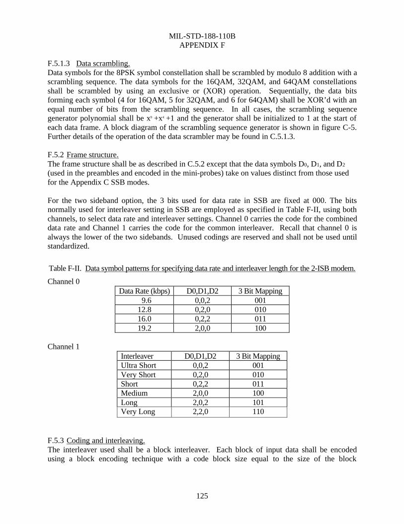
MIL-STD-188-110B
APPENDIX F
125
F.5.1.3 Data scrambling. Data symbols for the 8PSK symbol constellation shall be scrambled by modulo 8 addition with a scrambling sequence. The data symbols for the 16QAM, 32QAM, and 64QAM constellations shall be scrambled by using an exclusive or (XOR) operation. Sequentially, the data bits forming each symbol (4 for 16QAM, 5 for 32QAM, and 6 for 64QAM) shall be XOR’d with an equal number of bits from the scrambling sequence. In all cases, the scrambling sequence generator polynomial shall be x9 +x4 +1 and the generator shall be initialized to 1 at the start of each data frame. A block diagram of the scrambling sequence generator is shown in figure C-5. Further details of the operation of the data scrambler may be found in C.5.1.3. F.5.2 Frame structure. The frame structure shall be as described in C.5.2 except that the data symbols D0, D1, and D2 (used in the preambles and encoded in the mini-probes) take on values distinct from those used for the Appendix C SSB modes. For the two sideband option, the 3 bits used for data rate in SSB are fixed at 000. The bits normally used for interleaver setting in SSB are employed as specified in Table F-II, using both channels, to select data rate and interleaver settings. Channel 0 carries the code for the combined data rate and Channel 1 carries the code for the common interleaver. Recall that channel 0 is always the lower of the two sidebands. Unused codings are reserved and shall not be used until standardized. Table F-II. Data symbol patterns for specifying data rate and interleaver length for the 2-ISB modem.
Channel 0 Data Rate (kbps) D0,D1,D2 3 Bit Mapping
9.6 0,0,2 001 12.8 0,2,0 010 16.0 0,2,2 011 19.2 2,0,0 100
Channel 1
Interleaver D0,D1,D2 3 Bit Mapping Ultra Short 0,0,2 001 Very Short 0,2,0 010 Short 0,2,2 011 Medium 2,0,0 100 Long 2,0,2 101 Very Long 2,2,0 110
F.5.3 Coding and interleaving. The interleaver used shall be a block interleaver. Each block of input data shall be encoded using a block encoding technique with a code block size equal to the size of the block

MIL-STD-188-110B
APPENDIX F
126
interleaver. Thus, the input data bits will be sent as successive blocks of bits on both channels that together span the duration of the interleaver length selected. Table F-III shows the number of input data bits per block as function of both data rate and interleaver length. Note that an “input data block” should not be confused with the 256 symbol data block that is part of a data frame in the waveform format. The bits from an input data block will be mapped through the coding and interleaving to the number of data frames, and thus 256 symbol data blocks, that define the interleaver length.
TABLE F-III. Input data block size in bits as a function of data rate and interleaver length
Interleaver Length in Frames 1 3 9 18 36 72
Data Rate
(kbps) Number of Input Data Bits per Block 9.6 1,152 3,456 10,368 20,736 41,472 82,944 12.8 1,536 4,608 13,824 27,648 55,296 110,592 16.0 1,920 5,760 17,280 34,560 69,120 138,240 19.2 2,304 6,912 20,736 41,472 82,944 165,888
F.5.3.1 Block boundary alignment. Each code block shall be interleaved within a single interleaver block of the same size. The boundaries of these blocks shall be aligned such that the beginning of the first data frame following each reinserted preamble shall coincide with an interleaver boundary. Thus for an interleaver length of 3 frames, the first three data frames following a reinserted preamble will contain all of the encoded bits for a single input data block. The first data symbol from the first data frame in each interleaver set shall have as its MSB the first bit fetched from the interleaver. This is no different from what would normally be expected, but is a requirement. F.5.3.2 Block encoding. See C.5.3.2. F.5.3.3 Block interleaver structure. The block interleaver used is designed to separate neighboring bits in the punctured block code as far as possible over the span of the interleaver with the largest separations resulting for the bits that were originally closest to each other. F.5.3.3.1 Interleaver size in bits. The interleaver shall consist of a single dimension array, numbered from 0 to its size in bits –1. The array size shall depend on both the data rate and interleaver length selected as shown in table F-IV.
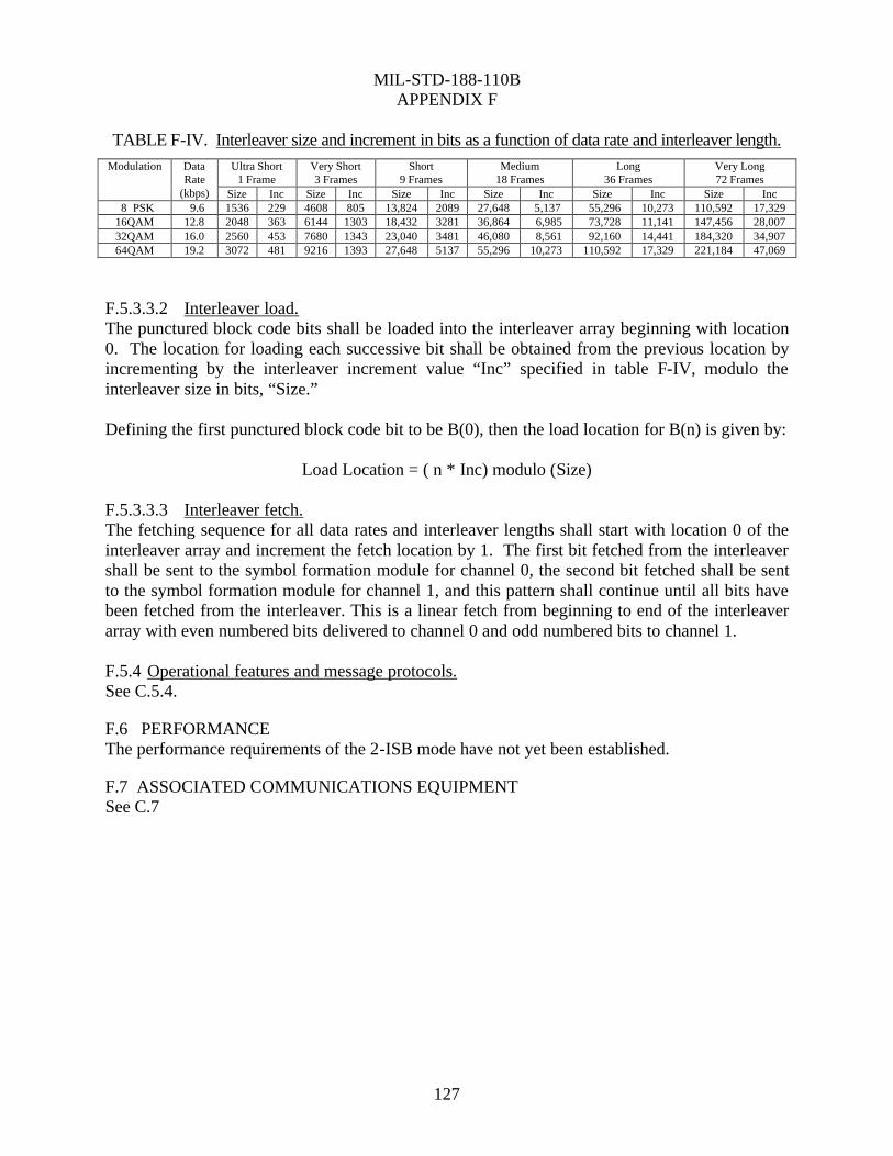
MIL-STD-188-110B
APPENDIX F
127
TABLE F-IV. Interleaver size and increment in bits as a function of data rate and interleaver length. Ultra Short
1 Frame Very Short 3 Frames
Short 9 Frames
Medium 18 Frames
Long 36 Frames
Very Long 72 Frames
Modulation Data Rate
(kbps) Size Inc Size Inc Size Inc Size Inc Size Inc Size Inc 8 PSK 9.6 1536 229 4608 805 13,824 2089 27,648 5,137 55,296 10,273 110,592 17,329 16QAM 12.8 2048 363 6144 1303 18,432 3281 36,864 6,985 73,728 11,141 147,456 28,007 32QAM 16.0 2560 453 7680 1343 23,040 3481 46,080 8,561 92,160 14,441 184,320 34,907 64QAM 19.2 3072 481 9216 1393 27,648 5137 55,296 10,273 110,592 17,329 221,184 47,069
F.5.3.3.2 Interleaver load. The punctured block code bits shall be loaded into the interleaver array beginning with location 0. The location for loading each successive bit shall be obtained from the previous location by incrementing by the interleaver increment value “Inc” specified in table F-IV, modulo the interleaver size in bits, “Size.” Defining the first punctured block code bit to be B(0), then the load location for B(n) is given by:
Load Location = ( n * Inc) modulo (Size)
F.5.3.3.3 Interleaver fetch. The fetching sequence for all data rates and interleaver lengths shall start with location 0 of the interleaver array and increment the fetch location by 1. The first bit fetched from the interleaver shall be sent to the symbol formation module for channel 0, the second bit fetched shall be sent to the symbol formation module for channel 1, and this pattern shall continue until all bits have been fetched from the interleaver. This is a linear fetch from beginning to end of the interleaver array with even numbered bits delivered to channel 0 and odd numbered bits to channel 1. F.5.4 Operational features and message protocols. See C.5.4.
F.6 PERFORMANCE The performance requirements of the 2-ISB mode have not yet been established.
F.7 ASSOCIATED COMMUNICATIONS EQUIPMENT See C.7

MIL-STD-188-110B
128
CONCLUDING MATERIAL Custodians: Preparing activity:
Air Force - 90 Air Force - 90 Army - SC Navy - EC
Review activities: (Project IXMP-00361) Army - CR Navy- MC DoD - DC, NS, JT

STANDARDIZATION DOCUMENT IMPROVEMENT PROPOSAL INSTRUCTIONS
1. The preparing activity must complete blocks 1, 2, 3, and 8. In block 1, both the document number and revision letter should be given.
2. The submitter of this form must complete blocks 4, 5, 6, and 7, and send to preparing activity.
3. The preparing activity must provide a reply within 30 days from receipt of the form.
NOTE: This form may not be used to request copies of documents, nor to request waivers, or clarification of requirements on current contracts. Comments submitted on this form do not constitute or imply authorization to waive any portion of the referenced document(s) or to amend contractual requirements.
I RECOMMEND A CHANGE: 1. DOCUMENT NUMBER
MIL-STD-188-110B 2. DOCUMENT DATE (YYMMDD)
000309 3. DOCUMENT TITLE Interoperability and Performance Standards for Data Modems 4. NATURE OF CHANGE (Identify paragraph number and include proposed rewrite, if possible. Attach extra sheets as needed.)
5. REASON FOR RECOMMENDATION
6. SUBMITTER a. NAME (Last, First, Middle Initial)
b. ORGANIZATION
c. ADDRESS (Include Zip Code)
d. TELEPHONE (Include Area Code) (1) Commercial
(2) AUTOVON (If applicable)
7. DATE SUBMITTED (YYMMDD)
8. PREPARING ACTIVITY a. NAME
Air Force Communications Agency b. TELEPHONE (Include Area Code)
(1) Commercial (618) 256-2975 (2) AUTOVON 576-2975
c. ADDRESS (Include Zip Code) ATTN: ITS Scott Air Force Base, IL 62225-5238
IF YOU DO NOT RECEIVE A REPLY WITHIN 45 DAYS, CONTACT: Defense Standardization Program Office (DLSC-LM) 8725 John J. Kingman road, Suite 2533 Ft. Belvoir, VA 22060-2533 Telephone (703) 767-6888 AUTOVON 427-6888
DD FORM 1426, FEB 1999 (EG) PREVIOUS EDITION IS OBSOLETE WHS/DIOR, Feb 99