department of civil engineering engineering …
TRANSCRIPT

STBCET CIVIL/EM/ Page 1
SHRI TULJABHAVANI TEMPLE TRUST’SSHRI
TULJABHAVANI COLLEGE OF ENGINEERING,
TULJAPUR.
DEPARTMENT OF CIVIL ENGINEERING
ENGINEERING MECHANICS
LAB MANUAL
PreparedBy ApprovedBy
Prof.S.D.Sagare Hangargekar P.A.
Subject Incharge H.O.D. Civil

STBCET CIVIL/EM/ Page 2

STBCET CIVIL/EM/ Page 3
DEPARTMENT OF CIVIL ENGINEERING
ENGINEERING MECHANICS
LIST OF EXPERIMENTS
SR.NO. NAMEOFTHE EXPERIMENT PAGE
NO.
01 Study of Simple Machines 03
02 Polygon Law of Coplanar Forces 07
03 Centre of gravity of Irregular Shaped Bodies 11
04 Bell Crank Lever 14
05 Support Reaction for Beam 18
06 Simple/ Compound Pendulum 22
07 Inclined Plane (To determine coefficient of friction) 26
08 Moment of Inertia of a Fly Wheel 30
09 Simple Screw Jack 34
10 Lami’s theorem 40
11. Application of Spreadsheet Program 44
Time Allotted for each Practical Session = 02 Hrs.

STBCET CIVIL/EM/ Page 4
EXPERIMENT NO. 01
STUDY OF SIMPLE MACHINES
STBCET CIVIL/EM/ Page 5
EXPERIMENT NO. 01
STUDY OF SIMPLE MACHINES
Aim: To study simple machines.
Machine:
It is a device by means of which a small effort applied at one part of it is
transmitted to another to secure an advantage to lift a heavy load.
Load (W):
This is that part of resistance which machine has to overcome and which is of
the use to the operator.
Effort (P):
This is the force necessary to work the machine so as to overcome the load and
any other resistance against movement
Mechanical advantage (M.A.):
This is the ratio of the load applied to the effort applied to the machine i.e.
M.A. = load applied / effort applied = W / P
Velocity Ratio (V.R.):
This is the ratio of the distance moved by the effort in any interval of time to the
corresponding distance, moved by the load in the same interval of time.
V.R. = Distance moved by effort / Distance moved by load = Sp / Sw
Input of machine:
This is the total work done on the machine. This is the energy supplied to the
machine. This is same as work done by the effort. The importance of machine is
to lift the load and overcome the resistance. (Friction of the machine)
Resistance of machine:
This is the resistance against the movement of load. Resistance of the machine
is mainly due to the friction between the moving parts of the machine.

STBCET CIVIL/EM/ Page 6
Output of machine:
This is the useful work done.
Efficiency of machine: ():
This is ratio of output of machine to the input. This is also same as the ratio of
useful work done by the machine to the energy supplied to it.
Efficiency of machine = output of machine / input of machine
= useful work done / actual energy supplied
= (W * Sw) / (P *Sp)
= (W/P) / (Sp/Sw)
= M.A. / V.R.
% = (M.A. / V.R.)*100 i.e. efficiency in %.
Ideal machine:
This machine is absolutely free from the frictional resistance. Since no
resistance are in the energy supplied equal to the useful work done i.e., for ideal
machine,
Ideal Effort (Pi):
Input = Output
W / P = Sp / Sw
P*Sp = W * Sw
M.A. = V.R.
For ideal machine V.R. = M.A. i.e. W/P = V.R.
Therefore P = W / V.R.
Hence ideal effort is the ratio of load applied to the velocity ratio.
Pi = W / V.R.

STBCET CIVIL/EM/ Page 7
Frictional Effort (Pf):
Frictional effort = Actual effort – Ideal effort
Pf = Pa – Pi
Law of machine:
The relation between the efforts required in the machine to lift a load is called
as a law of machine. It can be expressed in the form of:
P = mW + C
Where, P = Effort applied in ‗N‘
W = Load applied in ‗N‘
m= Slope of graph line (Graph of actual effort Vs Load)
C = Intercept of line on Y axis / Constant.
Reversibility of simple machine:
If load and effort are changed whether the machine works or not is called
reversibility of machine.
If efficiency of machine is >= 50%, machine is reversible.
If efficiency of machine is <50%, machine is irreversible / self locking.
Questions:
1. What ismachine?
2. What is MechanicalAdvantage?
3. What is VelocityRatio?
4. What is the unit ofM.A.?
5. What is input & output ofmachine?
6. What is efficiency ofmachine?
7. M.A. = V.R, condition for whichmachine?
8. What is idealeffort?
9. What is frictionaleffort?
10. What is Law of machine?Explain.
11. What is reversibility of machine? Explain with example.

STBCET CIVIL/EM/ Page 8
EXPERIMENT NO. 02
POLYGON LAW
OF
COPLANAR FORCES

STBCET CIVIL/EM/ Page 9
P4
P5
P2
P3
P1
Foot screw
P3
P2
String P4
P1 P5
Ө2
5
1
Ө
Ө 3
Ө
Ө4
Figure: Force Table

STBCET CIVIL/EM/ Page 10
EXPERIMENT NO. 02
POLYGON LAW OF COPLANAR FORCES
Aim: To verify law of polygon and calculate the resultant of coplanar
concurrent force system
Equipment: Force table, pulleys, set of weights, light inextensible string, spirit
level, and circular ring.
Theory: If more than three coplanar concurrent forces are acting on rigid body
be represented by the sides of polygon taken in order (tail of second force
coincides with tip of first force) then, closing line of polygon represents the
resultant taken in reverse order (tip of resultant force coincides with tip of last
force). At equilibrium force is zero. Therefore, tail of the first force coincides
with tip of last force i.e. polygon is closed figure.
Procedure:
1. Organize the physical set up of experiment & studyit.
2. Level the force table by adjusting the foot screws &check it with help of
bubbletube.
3. Apply the forces P1, P2, P3, P4& P5 so that the pivot remains at centre of
ring. Note down the magnitude & direction offorces.
4. Observe the angles between consecutive forces & noteit.
5. Draw space diagrams for each reading using Bow‘s notation & then draw
the force polygon with proper scale for all forces on graphpaper.
6. Observe the nature of polygon whether it is open orclosed.
7. Apply unknown weight on one of the string & adjust the forces in other
strings to so that the pivot remains at centre ofring.
8. Find the unknown weight by drawing space diagram & forcepolygon.

STBCET CIVIL/EM/ Page 11
Observation Table:
Sr.
No.
Magnitude of forces (N) Angle between consecutive
forces Remark
P1 P2 P3 P4 P5 θ1 θ2 θ3 θ4 θ5
1.
2.
3.
4.
Calculations: Analytical Calculations
Result:
Sr.No. Resultant calculated by analytical method
Resultant calculated by graphical method
1.
2.
3.
4.
Conclusion:
Resultant of the force system calculated by analytical method and graphical
method is ………. (Nearly same / exactly same).
STBCET CIVIL/EM/ Page 12
EXPERIMENT NO.03
CENTRE OF GRAVITY OF IRREGULAR
OBJECTS
STBCET CIVIL/EM/ Page 13
STBCET CIVIL/EM/ Page 14
EXPERIMENT NO.03
Aim: To determine the centre of gravity of irregular objects.
Material Required: Cardboards of different shapes, thread, nail, pencil,
rule/straight edge, load, etc.
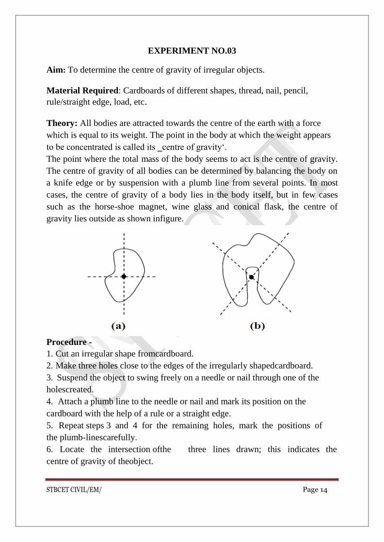
Theory: All bodies are attracted towards the centre of the earth with a force
which is equal to its weight. The point in the body at which the weight appears
to be concentrated is called its ‗centre of gravity‘.
The point where the total mass of the body seems to act is the centre of gravity.
The centre of gravity of all bodies can be determined by balancing the body on
a knife edge or by suspension with a plumb line from several points. In most
cases, the centre of gravity of a body lies in the body itself, but in few cases
such as the horse-shoe magnet, wine glass and conical flask, the centre of
gravity lies outside as shown infigure.
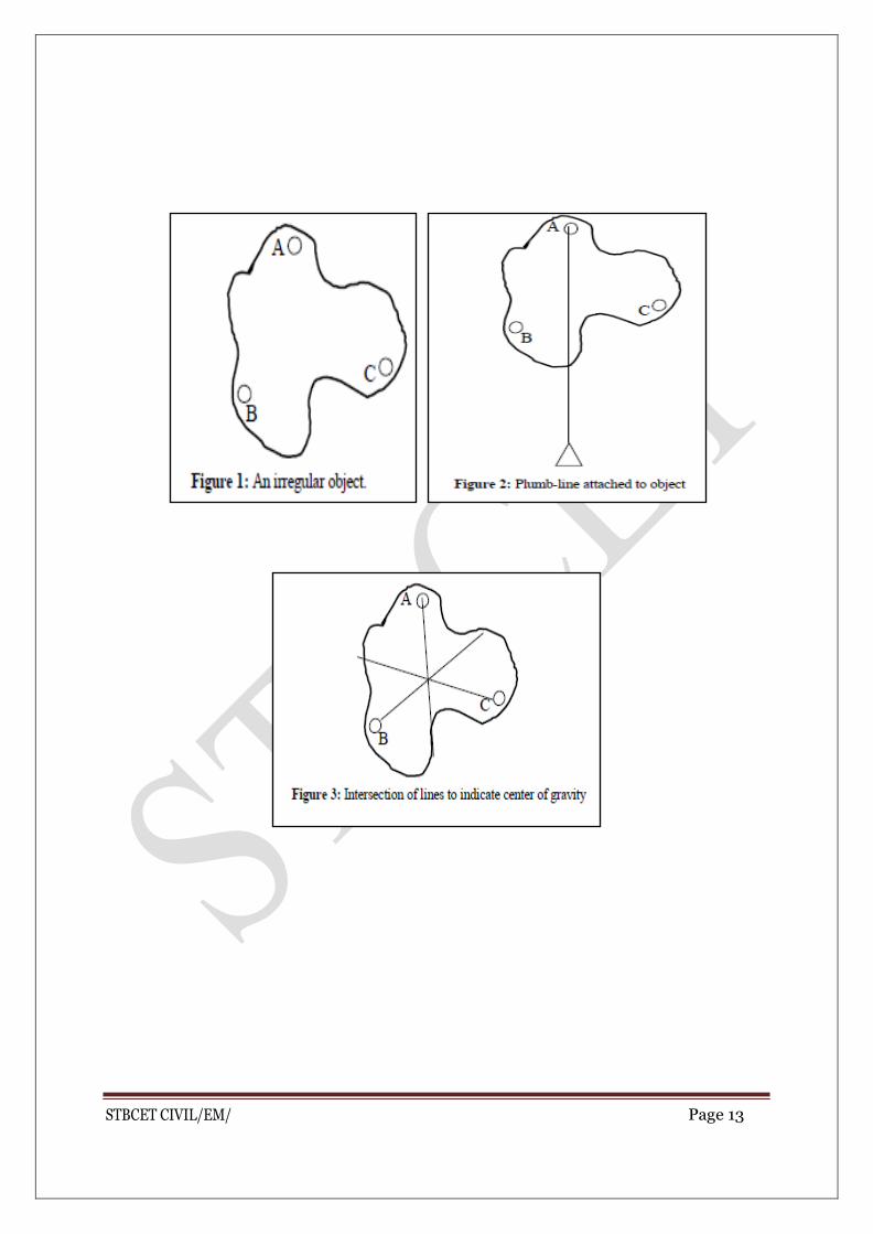
Procedure -
1. Cut an irregular shape fromcardboard.
2. Make three holes close to the edges of the irregularly shapedcardboard.
3. Suspend the object to swing freely on a needle or nail through one of the
holescreated.
4. Attach a plumb line to the needle or nail and mark its position on the
cardboard with the help of a rule or a straight edge.
5. Repeat steps 3 and 4 for the remaining holes, mark the positions of
the plumb-linescarefully.
6. Locate the intersection ofthe three lines drawn; this indicates the
centre of gravity of theobject.

STBCET CIVIL/EM/ Page 15
EXPERIMENT NO.04
BELL CRANK LEVER

STBCET CIVIL/EM/ Page 16
Figure. Bell Crank Lever

STBCET CIVIL/EM/ Page 17
EXPERIMENT NO.04
BELL CRANK LEVER
Aim: To verify the Principle of Moments using the Bell Crank Lever apparatus.
Apparatus: Bell crank lever apparatus, hangers, weights, scale.
Theory: Principle of Moments states, ‗the algebraic sum of the moments of a
system of coplanar forces about any point in the plane is equal to the moment of
the resultant force of the system about the same point‘.
This principle would be verified for a bell crank lever arrangement.
A lever whose two arms form a right angle, or nearly a right angle and having
its fulcrum at the apex of the angle is referred to as a bell crank lever. These
levers were originally used to operate the bell from a long distance especially
where change in direction of bell wires was involved and hence the name. Now
bell crank levers are used in machines to convert the direction of reciprocation
movement.
Procedure:
1. Arrange three hangers at arbitrary locations on the horizontal arm. Note the
locations x1, x2, and x3 of these hangers from the hinge. Adjust the tension in
the spring connected to the vertical arm such that the two pointers come in the
same vertical line. In this position the horizontal arm is truly horizontal. Note
the tensile force in the spring as the initial tension Ti. Also note the location Y
of the spring from thehinge.
2. Hang the weights W1, W2 and W3 from the hangers. This will cause the
arms to tilt and the pointers to move away from each other. Now adjust the
tension in the spring such that the pointers once again come in the same vertical
line. The horizontal arm is once again in its horizontal position. Note the tensile
force in the spring as the final tension Tf. The tensile force T on the vertical arm
is the difference Tf —Ti.
3. Since the external forces are being supported by the single hinge at the apex
of the arms, implies that the resultant of these external applied forces passes
through the supporting hinge. Therefore to verify the principle of moments we
need to take moments (ΣM) of all the external forces (which includes the
weights of the hangers hanging from the horizontal arm and the tension inthe

STBCET CIVIL/EM/ Page 18
spring connected to the vertical arm) about the hinge and if the total sum is zero,
verifies the law of moments since the moment of the resultant is also zero at the
hinge.
4. Repeat the above steps by changing the weights and their location on the
horizontal arm for two more set ofobservations.
Observation Table:
Sr. No.
Ti (N)
Y (m)
W1 (N)
W2 (N)
W3 (N)
X1 (m)
X2 (m)
X3 (m)
Tf (N)
T= Tf -Tn
ΣM=T*Y-W1*X1 -W2*X2 -W3*X3
1.
2.
3.
Calculations:
Summation moments of all external forces at the hinge O.
ΣMo =T*Y-W1*X1 -W2*X2 -W3*X3
RESULT:
The sum of moments of all the applied external forces on the bell crank lever,
within limits of experimental error being close to zero, is in accordance to the
‗Principle of Moments‘.
Hence the experiment is verified.

STBCET CIVIL/EM/ Page 19
EXPERIMENT NO. 5
EQUILIBRIUM OF PARALLEL FORCES
STBCET CIVIL/EM/ Page 20
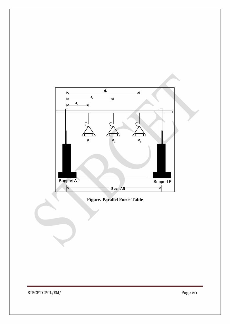
Figure. Parallel Force Table

STBCET CIVIL/EM/ Page 21
EXPERIMENT NO. 5
EQUILIBRIUM OF PARALLEL FORCES
Aim: To study Equilibrium of parallel forces – simply supported beam
reactions.
Apparatus: Beam reaction apparatus, hooks & weights with hangers.
Theory: When system of parallel forces act on body & keeps the body in
equilibrium then algebraic sum of forces is equals to zero & sum of moment of
forces (active & reactive) about any point in plane of forces is equals to zero.
Procedure:
1. Organize the physical set up of experiment studyit.
2. Measure span ofbeam. 3. Note down initial reading (reactive forces) at support A &B.
4. Apply loads P1, P2, (active forces) at different positions & measure the
distances d1, d2, respectively from support A & noteit.
5. Take final readings of reactive forces at supports A & B after loading&
note down in observationtable.
6. Calculate analytically support reaction at support A &B. 7. Compare the support reactions at supports A & B calculated by analytical
method with support reactions calculated by deducting initial readings
from final readings at eachsupport.
8. Repeat the procedure for four sets ofloadings.
Observation:
a) Span of AB = L = ………………mm
b) Initial readings at support A=…………………N
c) Initial readings at support B=…………………N

STBCET CIVIL/EM/ Page 22
Observation table:
Sr. No.
Loads (N)
Distance from support A
SupportReactions Support reactions by analytical method
Remark
P1 P2 D1 D2 AtA At B Ra Rb
Final Reading (gm)
Ra (N)
Final Reading (gm)
Rb (N)
1.
2.
3.
4.
Result:
Sr. No. Reactions calculated by Experimental method
Reactions calculated by Analytical method
1.
2.
3
4.
Conclusion: Support reactions calculated by analytical method and
experimental method are …………… (Nearly same/ exactly same)
STBCET CIVIL/EM/ Page 23
EXPERIMENT NO.6
COMPOUND PENDULUM
STBCET CIVIL/EM/ Page 24
EXPERIMENT NO.6
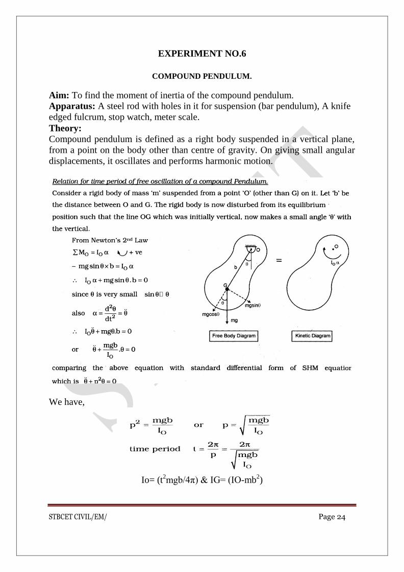
COMPOUND PENDULUM.
Aim: To find the moment of inertia of the compound pendulum. Apparatus: A steel rod with holes in it for suspension (bar pendulum), A knife
edged fulcrum, stop watch, meter scale.
Theory:
Compound pendulum is defined as a right body suspended in a vertical plane,
from a point on the body other than centre of gravity. On giving small angular
displacements, it oscillates and performs harmonic motion.
We have,
Io= (t2mgb/4π) & IG= (IO-mb
2)

STBCET CIVIL/EM/ Page 25
Observations:
Mass of uniform bar, m= ------kg
No. of oscillations = 20
Length of the bar L = 1m
Analytically,
IG =mL2/12
Sr. No.
b
(m)
T(sec) t=T-20 (sec)
Io=(t2mgb/4π)
IG=(IO- mb2)
IG (Average)

STBCET CIVIL/EM/ Page 26
Result:-
1. Moment of inertia of the compound pendulum(experimental)
=………………… 2. Moment of inertia of the compound pendulum(analytical)
=………………………

STBCET CIVIL/EM/ Page 27
EXPERIMENT NO.7
FRICTION
STBCET CIVIL/EM/ Page 28
EXPERIMENT NO.7
FRICTION
Aim: To find the Coefficient of Friction between two surfaces.
Apparatus: Inclined Plane with pulley, weights, block, weight pan, etc.
Theory: Friction force is developed whenever there is a motion or tendency of
motion of one body with respect to the other body involving rubbing of the
surfaces of contact. Friction is therefore a resistance force to sliding between
two bodies produced at the common surfaces ofcontact.
Friction occurs because no surface is perfectly smooth, however flat it may
appear. On every surface there are ‗microscopic hills and valleys‘ and due to
this the surfaces get interlocked making it difficult for one surface to slide over
the other. During static state the friction force developed at the contact surface
depends on the magnitude of the disturbing force. When the body is on the
vergeofmotionthecontactsurfaceoffersmaximumfrictionalforcecalledas
‗Limiting Frictional Force‘.
In 1781 the French Physicist Charles de Coulomb found that the limiting
frictional force did not depend on the area of contact but depends on the
materials involved and the pressure (normal reaction) between them.
Thus frictional force F α N, or
F = μsN
Here μs is the coefficient of static friction, a term introduced by Coulomb. The
value of lies between 0 and 1 and it depends on both the surfaces of contact.
Coefficient of static friction ‗μs‘ between two surfaces can be found out
experimentally by two methods, viz. Angle of Repose method and Friction
Planemethod.
The minimum angle of an inclined plane at which a body kept on it slides down
the plane without the application of any external force is known as Angle of
Repose. It is denoted by letter φ.
Angle of repose, φ = tan-1 μs

STBCET CIVIL/EM/ Page 29
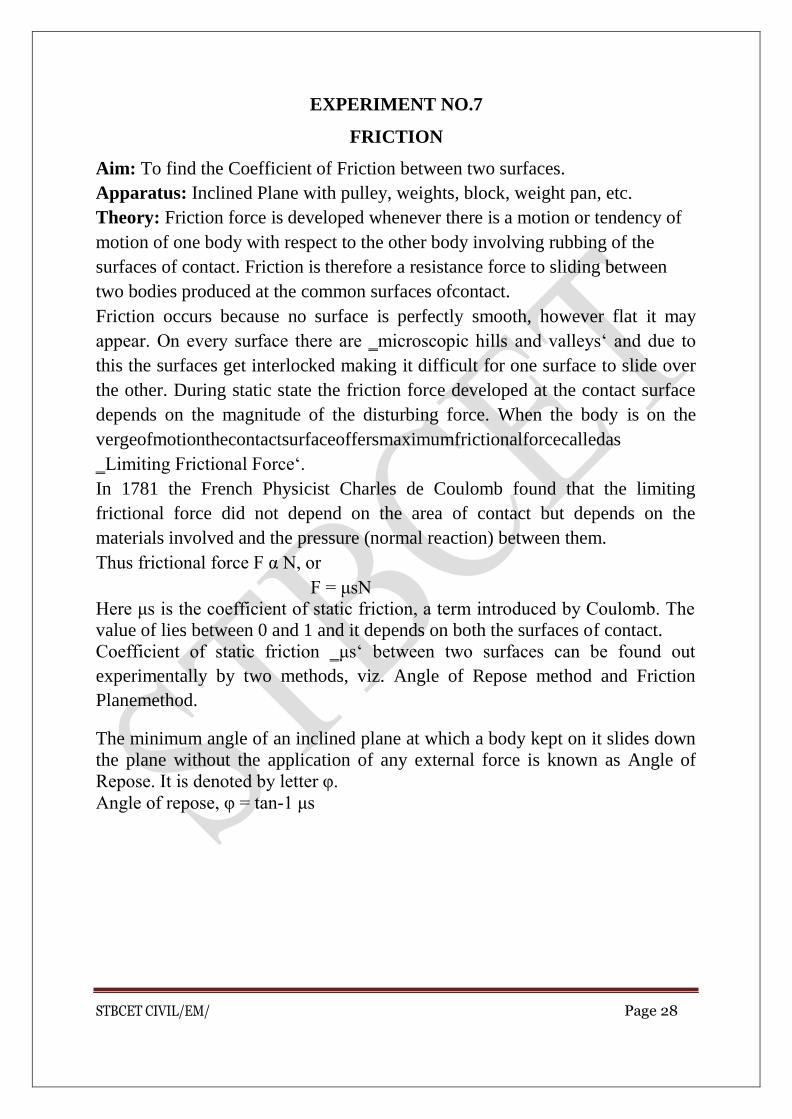
PROCEDURE
1. Set the inclined plane with glass top at some angle with the horizontal. Note
the inclination θ of the plane on the quadrant scale. Take a box of known
weight, note its bottom surface (whether surface is soft wood, or sand paper, or
card board etc,) and weight W (weight ofbox)
2. Tie a string to the box and passing the string over a smooth pulley, attach an
effort pan toit.
3. Slowly add weights in the effort pan. A stage would come when the effortpan
just slides down pulling the box up the plane. Using fractional weights up to a
least count of 5 gm, find the least possible weight in the pan that causes the box
to just slide up the plane. Note the weight in the effort pan. This isforce
‗P‘.
W
W Cosθ
F
W Sinθ
P
N

STBCET CIVIL/EM/ Page 30
4. Repeat the above steps 1 to 3 by changing the weights in the box for two
more sets ofobservations.
Observation Table:
Type of
surface
Weig
ht of
block
(W)
in
‗N‘
Angle
of the
Plane
(θ)
Weight
in
effort
pan (P)
in ‗N‘
Coefficient
of Friction
(µ)
Avera
ge (µ)
Angle of Repose
Analytical experimental
Wood
Carpet
Cloth
Result :
Coefficient of friction between glass and wood is………………….
Coefficient of friction between glass and carpet cloth is ……………..
Conclusion :
Wooden block has smooth contacting surface than carpet cloth, therefore its
coefficient of friction is ……………(less than/ more than) carpet cloth.

STBCET CIVIL/EM/ Page 31
EXPERIMENT NO.08
MOMENT OF INERTIA OF FLYWHEEL
STBCET CIVIL/EM/ Page 32
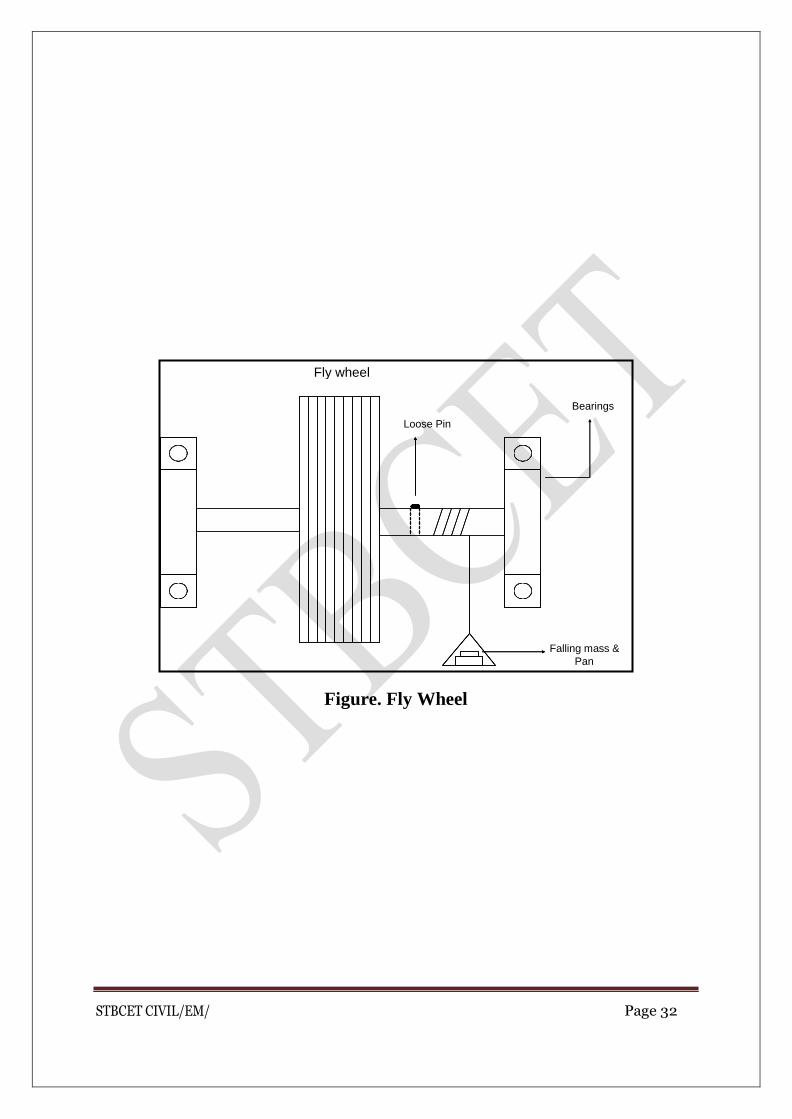
Figure. Fly Wheel
Fly wheel
Bearings
Loose Pin
Falling mass &
Pan

STBCET CIVIL/EM/ Page 33
EXPERIMENT NO.08
MOMENT OF INERTIA OF FLYWHEEL
Aim: To find moment of inertia of flywheel
Apparatus: Flywheel mounted on axle and supported by bearing, pan, weights,
and stop watch.
Theory:
Moment of Inertia is the property of the body by virtue of which it resists the
change in the state of its angular motion about any axis. It depends upon the
mass of the body and the distance with respect to axis of rotation.
For falling mass,
Initial velocity = v = 0
Height of fall = h
a= 2h/t2
Resultant force = T-mg
-F = T-mg
-ma = T-mg
T = m(g-a)
Moment ‗M‘ = Iα
T*r =I*a/r (since a=rα)
I =Tr2/a
I = m (g – a) r2 / a
Procedure:
Attach a long thread about 1.8 m length to the axle of flywheel and end of
thread is attached to the axle while the pan is attached to the outer end of the
thread. Weight should be added so that pan must be in suitable line on thewheel
STBCET CIVIL/EM/ Page 34
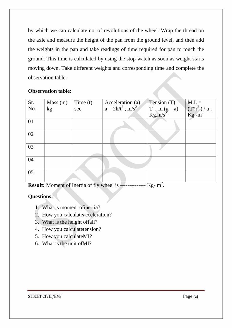
by which we can calculate no. of revolutions of the wheel. Wrap the thread on
the axle and measure the height of the pan from the ground level, and then add
the weights in the pan and take readings of time required for pan to touch the
ground. This time is calculated by using the stop watch as soon as weight starts
moving down. Take different weights and corresponding time and complete the
observation table.
Observation table:
Sr. No.
Mass (m)
kg
Time (t)
sec
Acceleration (a)
a = 2h/t2 , m/s
2
Tension (T)
T = m (g – a) Kg.m/s
2
M.I. =
(T*r2 ) / a ,
Kg -m2
01
02
03
04
05
Result: Moment of Inertia of fly wheel is -------------- Kg- m2.
Questions:
1. What is moment ofinertia?
2. How you calculateacceleration?
3. What is the height offall?
4. How you calculatetension?
5. How you calculateMI?
6. What is the unit ofMI?

STBCET CIVIL/EM/ Page 35
EXPERIMENT NO. 09
SIMPLE SCREW JACK

STBCET CIVIL/EM/ Page 36
Figure. Screw Jack
L
W
Pitch
Screw
P
STBCET CIVIL/EM/ Page 37
EXPERIMENT NO. 09
SIMPLE SCREW JACK
Aim: To study simple screw jack and find its V.R. and its various performances
Apparatus: Simple screw jack, thread, pan, weights etc…
Theory:
A screw jack is used to lift & support heavy loads. Jacks used for lifting trucks
or cars for repairs are screw jack. To lift such heavy loads, comparatively very
small effort is applied at the end of the handle.
Screw jack consists of a screw & a drum is mounted at its head. Load is kept on
the drum therefore it is called as Load drum. Load drum is rotated with the help
of the thread passing over the pulley and having effort applied at its end.
When screw jack completes on the rotation load drum will also complete one
rotation. Distance moved by effort is equals to the circumference of the load
drum at the same time load is lifted by distance equals to the pitch of the screw.
Therefore velocity ratio =Distance moved by effort
Distance moved by load
Procedure:
= Circumference ofloaddrum =CW
Pitch ofthe screw P
1. Observe the machine – ‗Screw Jack.‘ Identify the various components Such
as screw, load drum,pulley.
2. Measure the pitch of the screw and circumference of loaddrum.
3. Find the velocityratio.
4. Set up the machine and attach heavy loaddrum.

STBCET CIVIL/EM/ Page 38
5. Find corresponding effort (P) by gradually increasing the value so that when
effort (P) moves down, load (W) just starts moving up. Label the motions in the
diagram.
6. Repeat the procedure for different heavy loadW.
7. Draw the graph by taking load values on x-axis and effort values on Y-axis
with suitable scale. Note the co-linear relationship between efforts & loadW.
8. Find slope (m) and intercept (C) on y-axis for the straight line, and write
relation (in the form of P= (mW+C). Note this equation is called as Law of
machine.
9. Calculate mechanical advantage & subsequently efficiency for each set of
load (W) & corresponding effort (P) by relation MA= load (W) / Effort (P) &
efficiency (%η) = MA/V.R. x 100. Tabulate the same in observationtable.
10. Calculate ideal effort (Pi) for each of load (W) by a relation Pi = W / V.R. &
tabulate it. Note that effort (P) in actual machine is greater than ideal effort (Pi)
requiredinidealmachine.Plotthegraphofidealeffort-Pi(Ony-axis)&Load
– W (On x-axis).
11. Note linear relationship betweenthem.
12. Calculate effort lost in friction (Pf) ‗for each of the load (W) by relation
Pf = P – W / V.R. & tabulate thesame.
13. Plot the graph of ‗Effort lost in friction ‗Pf(on y-axis) against Load (W) on
X-axis. Note the linear relationship between Pf &W.
14. Draw an interference from the graphplotted.
15. Draw the graph taking load on x-axis and mechanical advantage &
efficiency ony-axis.
16. Calculate load loss in friction by the formula Wf= P x V.R. –W.
17. Find the maximum mechanical advantage & maximum efficiency for the
machine.

STBCET CIVIL/EM/ Page 39
Observations:
1. Diameter of load table:D
2. Pitch of Screw:p
3. Circumference of load table:πD
4. Velocity Ratio: Sp/Sw =πD/p
Observation Table:
Sr. No.
Load (W)
Newton
Effort
(Pa) Newton
M.A. =
W/Pa
η%=
M.A./V.R. * 100
Pi =
W/V.R.
Pf = Pa-Pi
01
02
03
04
05
Sample Calculations:
1. Load(W)= _N
2. Effort(P) = N
3. M.A. = W /P= N
4. Velocityratio= Distance moved by effort=
Distance moved by load
5. Efficiency(%)= M.A. ×100
V.R.
6. Law of machine =mW+C
STBCET CIVIL/EM/ Page 40
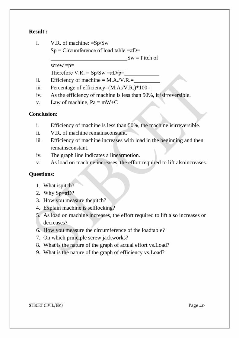
Result :
i. V.R. of machine: =Sp/Sw
Sp = Circumference of load table =πD=
Sw = Pitch of
screw =p=
Therefore V.R. = Sp/Sw =πD/p=
ii. Efficiency of machine = M.A./V.R.=
iii. Percentage of efficiency=(M.A./V.R.)*100= _
iv. As the efficiency of machine is less than 50%, it isirreversible.
v. Law of machine, Pa = mW+C
Conclusion:
i. Efficiency of machine is less than 50%, the machine isirreversible.
ii. V.R. of machine remainsconstant.
iii. Efficiency of machine increases with load in the beginning and then
remainsconstant.
iv. The graph line indicates a linearmotion.
v. As load on machine increases, the effort required to lift alsoincreases.
Questions:
1. What ispitch?
2. Why Sp=πD?
3. How you measure thepitch?
4. Explain machine is selflocking?
5. As load on machine increases, the effort required to lift also increases or
decreases?
6. How you measure the circumference of the loadtable?
7. On which principle screw jackworks?
8. What is the nature of the graph of actual effort vs.Load?
9. What is the nature of the graph of efficiency vs.Load?

STBCET CIVIL/EM/ Page 41

STBCET CIVIL/EM/ Page 42
EXPERIMENT NO.10
LAMI’S THEOREM
STBCET CIVIL/EM/ Page 43
EXPERIMENT NO.10
LAMI’S THEOREM
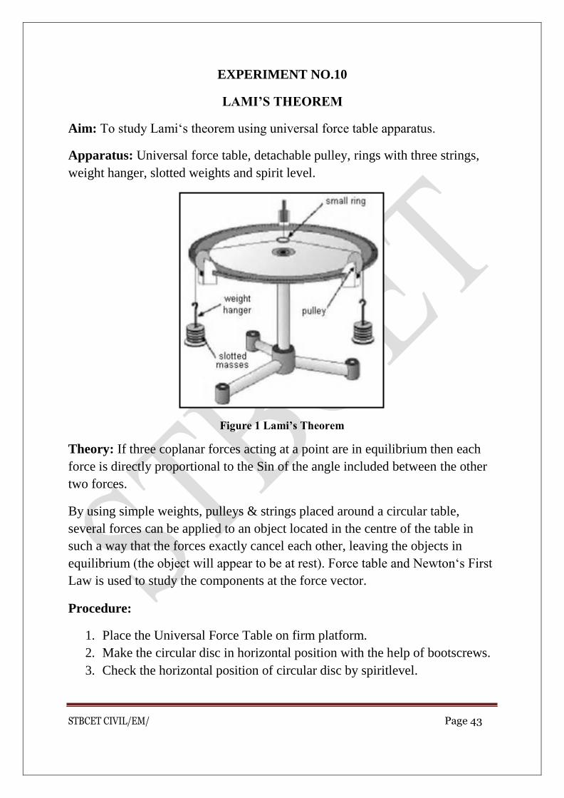
Aim: To study Lami‘s theorem using universal force table apparatus.
Apparatus: Universal force table, detachable pulley, rings with three strings,
weight hanger, slotted weights and spirit level.
Figure 1 Lami’s Theorem
Theory: If three coplanar forces acting at a point are in equilibrium then each
force is directly proportional to the Sin of the angle included between the other
two forces.
By using simple weights, pulleys & strings placed around a circular table,
several forces can be applied to an object located in the centre of the table in
such a way that the forces exactly cancel each other, leaving the objects in
equilibrium (the object will appear to be at rest). Force table and Newton‘s First
Law is used to study the components at the force vector.
Procedure:
1. Place the Universal Force Table on firm platform.
2. Make the circular disc in horizontal position with the help of bootscrews.
3. Check the horizontal position of circular disc by spiritlevel.

STBCET CIVIL/EM/ Page 44
4. Clamp the three detachable pulleys to the circular disc at threedifferent
positions.
5. Keep the ring at the centre of disc and pass the other ends of eachstring
over the threepulleys.
6. Hang three hangers to these ends of strings passing over thepulleys.
7. Put slotted weights to each hanger so as to make pivot and ringconcentric
with eachother.
8. Note the sum of slotted weights in each hanger and weight of hanger as
three forces F1, F2,F3.
9. Measure the angles included between the two adjacent pulleys andnote
them as θ1, θ2, θ3 as per figure no.(2)
10. Record these observations intable.
11. Repeat step (7) by changing one or two pulleys position and take two sets
ofobservation.
Observation Table:
Sr.
No.
Forces in‗N‘ (Wt.
in hanger + Wt. of hanger)
Included angles
between two forces in―degrees‖
Ratio of force and angle
between other two forces
F1 F2 F3 θ1 θ2 θ3 F1/sin θ1
F2/sin θ2
F3/sin θ3
01
02
03
Result:
The ratios obtained are:
1. F1/sinθ1=
2. F2/sinθ2=
3. F3/sinθ3=
STBCET CIVIL/EM/ Page 45
Conclusion:
The ratios obtained for each reading are…………. (same / nearly same/not
same)
Questions:
1. What are apparatus required for carrying outexperiment?
2. What is Lami‘stheorem?

STBCET CIVIL/EM/ Page 46
EXPERIMENT NO. 11
APPLICATION OF SPREADSHEET
PROGRAM

STBCET CIVIL/EM/ Page 47
Σ Fy = 0 ( ↑ +ve, ↓-ve)
RA + RB - W1 - W2 = 0
RA + RB = W1 + W2
Input Load KN Length M
1 W1 10 L1 0.2
2 W2 10 L2 0.8
3 L 1
Output Reactions
RA +RB = 20
RA = 10
RB = 10
Simply Supported Beam Carrying Point Loads
Σ MA = 0 ( Clockwise +ve, Anti-clockwise -ve)
(W1 X L1 + W2 X L2 - RB X L ) =0
RB = (W1 X L1 + W2 X L2) / L

STBCET/CIVIL/SOM LAB Page 1
SHRI TULJABHAVANI TEMPLE TRUST’S
SHRI TULJABHAVANI COLLEGE OF ENGINEERING, TULJAPUR.
DEPARTMENT OF CIVIL ENGINEERING
STRENGTH OF MATERIAL
LAB MANUAL
Prepared By Approved By
Prof. Sagare S.D. Hangargekar P.A.
Lab In-charge H.O.D. Civil

STBCET/CIVIL/SOM LAB Page 2
Program Educational Objectives
I. Graduates of Civil Engineering Program will be prepared to take the challenges in the field of CivilEngineering.
II. To provide Graduates with a sound Knowledge in mathematical, scientific and Civil Engineering fundamentals required to solve engineering problems and also to pursue higher studies.
III. To train students with good scientific and engineering breadth in Construction industry & many field of CivilEngineering.
IV. To build the confidence of students leading to professional and ethical integrity, effective communication skill, leadership, so that they can apply engineering knowledge for betterment of society.
V. To provide a good competitive learning environment so that graduates of Civil Engineering will be ready to meet the needs of Indian and multinational constructionindustries.
Program specific outcomes
The students are able to demonstrate:
1. The knowledge of planning and designing of the system components for
building planning, transportation, water resources, estimating, costing and
scheduling the constructionprocesses.
2. The fundamental knowledge of analysis and design of various structures with
an understanding of associated safety, quality andeconomy.
3. The knowledge of field data collection and material characterization to provide
constructive and creative engineering solutions that reflect social and
environmentalsensitivities.

STBCET/CIVIL/SOM LAB Page 3
‘STRENGTH OF MATERIAL’ CLASS: - Second Year Civil / Mechanical Engineering
LIST OF EXPERIMENTS
Sr.
No. Name of Experiment
Page No.
From To
I Study of universal testing machine 03 04
II Tension test on mild steel bar 05 09
III Bending test on mild steel 10 10
IV Shear test on mild steel 11 13
V Hardness test (three metal specimens),
Rockwell hardness test on mild steel
14 15
VI Izod and Charpy impact test on any three metals 16 20
VII Torsion test on mild steel bar 21 23
VIII Bending test on Timber 24 26
IX Compressive strength of burnt clay building bricks 27 28
X Water absorption test on burnt bricks 29 29
Time Allotted for each Practical Session = 02 Hrs.
STBCET/CIVIL/SOM LAB Page 4
EXPERIMENT NO: I
STUDY UNIVERSAL TESTING MACHINE. (U.T.M.)
AIM:-To Study universal testing machine. (U.T.M.)
THEORY:-The U.T.M. serves for conditioning tests in tension, compression, bending, shear and hardness test for metals & other materials. The testing machine is operated hydraulically; driving is performed by the help of electricmotor.
The machine consists of two units:- A) The loading unit. B) The control panel.
A) The loading unit :- it consistsof
1. Robustbase.
2. Lowertable.
3. Lower compressionplate.
4. Upper compressionplate.
5. Lowercrosshead.
6. Uppercrosshead.
The main hydraulic cylinder is fitted in the center of the base and
piston slides in cylinder. A motor is fitted in the left hand side of the base. The
lower table is connected to main piston through a ball and back sit joint. The joint
ensures axial loading. The lower table is rigidly connected to the upper crosshead
by columns.
The lower table and upper crosshead assembly moves up and down with the
main piston. The jaws are inserted for tensile test specimen along with the rack jaws
slide in the lower and upper crosshead jaw, locking handle is provided to lock the jaws
of lower crosshead after specimen is clamped. The arrangement ensures firm
clamping of the specimen and easy take out of the broken specimen separate job
pieces are provided for different range of specimen diameters, it should be noted that
the jaws always be released slowly and the upper end & lower jaws are non-
interchangeable.
The space between the lower table and lower crosshead is used
for compression, bending, shear, and hardness test and the space between lower
STBCET/CIVIL/SOM LAB Page 5
and upper Crosshead is used for tension test. In any test the up & down motion of
the lower table and upper crosshead assembly performs the loading action. The
mechanical up & down motion of the lower crosshead is provided for rapid initial
space arrangement depending upon length and height of the tension and
compression test specimen respectively.
B) The control panel :- It consists of
1. Load indicatingdial.
2. Flow controlvalve
3. Returnvalve.
4. Range adjuster knob.
5. Recordingdrum.
6. Zero adjustingpanel.
The control panel consists of the oil tank containing the hydraulic oil. Two balls on the
control panel are used to control the oil flow in hydraulic system the right side valve is
pressure compensated flow control valve with integral overload relief valve. The left side
valve is a return valve. The valve allows the oil from the cylinder to go back to the tank
there by reducing the pressure in the cylinder and then the working piston can be
adjusted by this valve. If the return valve is closed oil delivered by the pump passes
through the flow control valve to the cylinder and piston goes up.
A big load indicating dial fitted with a glass cover mounted at front side of the
control panel. The range indicating dial located at the back side of the load indicating
dial, is to be adjusted for the particular range selected. A range adjuster knob is provided
for this adjustment. A zero adjusting knob is provided at right hand side to serve for
initial zero adjustment.
Conclusion:-The universal testing machine has capability to evaluate tensile,compression, shear, bending and hardness properties for different materials and metals.
STBCET/CIVIL/SOM LAB Page 6
EXPERIMENT NO: II
TENSION TEST ON M.S.BAR
AIM:-To conduct tension test on a mild steel specimen.
APPARATUS: - 1) Universal testing machine 2)Extension meter, to measure elongation
of thebar 3) Verniercaliper 4) Scale
THEORY:-The purpose of the test is to know the elastic properties, tensile strength and the ductility of steel. From this test we obtain 1) Stress-strain relationship of steel 2) Modulus of elasticity 3) Yieldstrength 4) Ultimate tensilestrength 5) Percentage elongation of steel at failure under tensileload
Behavior of steel under stress: -
Steel is an important material used in structure as well as machines while designing a steel member the designer should have an idea of the properties mention above. The knowledge of behavior of steel under stress is very essential up to a certain stress limit the steel behaves an elastic material but beyond that the steel behaves differently. The designer should have an idea of the young’s modulus of elasticity, the elastic limit & the maximum tensile strength. Also the percentage of elongation at failure is measure of ductility of steel. We get all this information from one single test i.e. tensile test on steel [or for other metalalso]In which a specimen is subjected to tensile load gradually till it fail.
Definitions: 1) Elasticity:- It is the property of material due to which a loaded material return to its initial space after the load is removed.
2) Proportional limit & elasticlimit:-
The limit of stress up to which the stress is proportional to the strain is called as limit of proportionality. The stress limit up to which if the load is removed the deformation disappears is called elastic limit. Both these limits are so close that for all practical purpose of proportionality & limit of elasticity are considered as same. The fig. shows stress strain diagram. Point A denotes this limit from 0 to A is a straight line. Thus the materials obey hook’s law up to this limit.
3) Yield point or yield stress:-
It is the stress at which the material changes from elastic stage to plastic stage & deformation occurs without increase in load up to point B. Beyond yield point, deformation does not disappear even if the loadremoved.

STBCET/CIVIL/SOM LAB Page 7
4) Ultimate stress or tensile strength:-
It is the maximum stress that is reached in the test divided by the original area of cross section. In the fig. The material begins to harden at point & it gains some strength. The stress increases till reaches a maximum value at point C.The deformation is also large from B&C.
5) Breaking load : -
Further deformation of the specimen beyond point C, taken place at much faster rate, & at reduced load. Finally it breaks at a stress denoted by point D. The load at which specimen breaks is called a breaking load.
Actually as the load increase beyond point B the cross section area of the bar is reduced considerably resulting in a neck formation somewhere at point C or beyond C. The specimen breaks at the neck.
6) Ductility :-
It is the property of material due to which the metal can absorb considerable mechanical energy without breaking in an irreversible form.
7) Gauge length :-
It is the length between two reference points marked on the specimen before tensile testing. Gauge length [Lo] is usually equal to 5 times diameter of specimen if the specimen is circular. The specimen is rectangular in cross section L0=5.65√ A0. Where, A0 is the area of cross section of the specimen
8) Percentage elongation :-
It is the percentage increase in the original length i.e. the gauge length, at the time of fracture of the specimen in the tensile test, measured by bringing the fractured parts together.
Let, L0 = original gauge length
L1 = distance between gauge marks after elongation, at failure. Then percentage elongation ∈ = L1 - L0 / L0 × 10
9) Percentage reduction in area :-
It is the reduction in area of cross section of the specimen at fracture expressed as percentage of original area of cross section. Let,
A0 =original area of cross section A1 =reduced area at fracture Then, A0 – A1 / A0 × 100=percentage reduction in area
Behavior of various metals: -
• Mild steel has got definite yield point. It contain carbon less than 0.3% medium carbon 0.8% to 1.5%.As the carbon content increases the ductility is reduced. High carbon steel does not show clear yieldpoint.
• Cast Iran is brittle, it does not exhibit any yield point, & it has a low limit of proportionality. It ductility is low [i.e. percentage elongation
STBCET/CIVIL/SOM LAB Page 8
isnegligible]
• Non-ferrous metals & their alloys: this also does not show a definite yield point & their limit of proportionality is low but they areductile.
PROCEDURE: -
1) Measure the diameter [d0] of the bar accurately in mm at 3 places & find mean value, correct up to 2 places of decimals. Also measure the gauge length accurately[L0].
2) Fix the specimen in the grip holders of the tensile testing machine firmly in such a way that the load is applied as axially aspossible.
3) Attach on extensometer firmly so as to measure that elongation during loading between the gaugemarks.
4) Bring the load indicating points of the dial to zero & apply load slowly at a suitable rate. The loading rate should be as uniform as possible & any change should be made gradually without anyshocks.
5) Note down the reading of load & elongation at regular intervals of 100kgload.
Also observe at what load the machine shows sudden increase in the deformation this occurs when yielding takes place.
6) Also observe at what load the machine shows sudden increase in the deformation this occurs when yielding takes place.
7) Beyond yield point extensometer may be removed & the reading of elongation taken on scale [during plastic deformation I.S.has recommended a rate of strain to be maintain at 0.15 per minute. J therate of loading may be increased to about 3kg/mm2/Sec. of the breaking load & corresponding elongation.
8) Remove the fracture pieces of the specimen, place them together touching at the fracture & measure the length [L1] between the gauge marks. Also measure the diameter of the specimen at fracture[d1]
9) Calculate stress & strain & plot the stress straindiagrams
10) Calculate stress at yielding point, maximum [ultimate] stress, breaking stress, percentage elongation & percentage reduction in area. Also calculate the modulus of elasticity. From thegraph, from the straight line portion of thegraph.
OBSERVATIONS: -
1) Original diameter of specimen=d0= _ _ _ _ __mm 2) Original gauge length =L0 =5d0 =_ _ _ _ _ __mm 3) Area of original cross section =A0=d02 / 4 mm2 4) Load at yield point= _ _ _ _ _ __N 5) Maximum load=_ _ _ _ _ _ __N 6) Breaking load= _ _ _ _ _ __N 7) Find length between gauge marks =L1 =_ _ _ _ _ __mm 8) Diameter of section after failure = d1=_ _ _ _ _ __mm 9) Area of cross section atfailure = A1= d02 / 4 mm2

STBCET/CIVIL/SOM LAB Page 9
OBSERVATION TABLE: -
Sr.no. Load(p) ‘N’ Elongation(dl) ‘mm’
Stress =P/A0
Strain =dl/L0
Remark Yieldpoint max.load breaking load.
1
2
3
4
CALCULATIONS: -
1) Calculate stress & strain in cal.4 & 5 of the observationtable 2) Stress at yield point = yield load/A0 =_ _ _ _ _ _ _N/mm2 3) Tensile strength = maximum load /A0 =_ _ _ _ _ _ __N/mm2
4) Breaking strength = breaking load /A0 =_ _ _ _ _ _ _ _N/mm2 5) Percentage elongation= L1-L0/L0×100 = _ _ _ _ _ __% 6) Percentage reduction in area = A0-A1/A0×100 = _ _ _ _ _ __% 7) Modulus of elasticity : from graph take two point on the straight portion
with co-ordinates X1,Y1 &X2,Y2
Modulus of elasticity = E = Y2-Y1/X2-X1 = _ _ _ _ _ _ _N/mm2
A) Stress Strain graph for MildSteel

STBCET/CIVIL/SOM LAB Page 10
B) Stress Strain graph for DifferentMaterials
a) Curve Ashows a brittle material. This material is also strong because there is little strain for a high stress. The fracture of brittle material is sudden and catastrophic, with little or no plastic deformation, Brittle materials crack under tension and the stress increases around the cracks. Cracks propagate less undercompression.
b) Curve B is strong material which is not ductile. Steel wire stretch very little and break suddenly. There can be a lot of elastic strain energy in a steel wire under tension and it will be “whiplash” if it breaks. The ends are razor sharp and failure is very dangerousindeed.
c) Curve C is a ductilematerial.
d) Curve D is a plastic material. Notice a very large strain for a small stress. The material will not go back to its originallength.

STBCET/CIVIL/SOM LAB Page 11
10
RESULTS: -
Yield point = ______________N/mm2
Tensile strength = ___________N/mm2 Breaking strength = ___________N/mm2 Percentage elongation = __________% _ Percentage reduction in area =___ _% Modulus of elasticity = __ _ _N/mm2
REQUIREMENTS: -
Mild steel should have following properties: Yield point = 260 N/mm2 Mod.of elasticity =2× 10⁵N/mm2
Percentage of elongation = 23%
Tensile strength = 420 N/mm2(minimum)
CONCLUSION: -The specimen of mild steel satisfies/does not satisfy the requirements

STBCET/CIVIL/SOM LAB Page 12
EXPERIMENT NO:III
BENDING TEST ON MILD STEEL
AIM:-To conduct cold bend test on mild steel bar.
APPARATUS: - a) Universal Testing Machine b) Suitable bend fixtures and test piece.
Test Piece: - Test bar of larger diameter should be reduced to a convenient size
between 20 and 50mm in diameter. Bar of less than 20 mm diameter shall be
tested without reduction in diameter.
PROCEDURE: - 1) Lay the test piece on two parallel supports and bend it in the
middle by means of a mandrel to the specified angle. The width of the supports and
of the mandrel should be greater than that if the test piece.
2) If it is necessary to observe the point at which cracking begins , the outer surface
of the test piece should remain clearly visible in the portion being bent while
conducting thetest.
3) The radius of the supports and the mandrel and the distance between there
supports shall be asspecified in the material specifications. If the distance between
the supports is not specified in the material specification, the distance should be
taken
approximately=D+3A
Where, D= Diameter of mandrel A= Angle of Bent OBSERVATIONS: - After bending the sides and outside of the bent portion should be examined. RESULT: - Report the results , if any crack or defect observed.
PRECAUTIONS: - a) Measure the diameter of the specimen at six locations and take the
mean.

STBCET/CIVIL/SOM LAB Page 13
b) Apply the bending force uniformly.
EXPERIMENT NO:IV
DIRECT SHEAR TEST ON METALS
AIM:-To determine the strength on steel in single shear and double shear.
APPARATUS:-
1. Universal TestingMachine,
2. Shear attachment withcutter,
3. Vernier caliper,
4. Scale.
THEORY:-
The purpose of the test is to find out the shear strength of steel specimen
subjected to single shear as well as double shear. This test is useful in the design of riveted joints as the rivets may be either in single shear or may be in double shear.
SHEAR STRESS:-
Shear stress is produced in a body when it is subjected to two equal and
opposite forces spaced at an infinitesimal distance or tangentially across the resisting section.
Shear stress (fs) = Shearing force/Area of resisting force = P/A
In case of rivet, the rivet has circular cross-section.
A = Πd2/4
In single shear,
fs1 =P1/A
A In double shear,
fs2 = P2/2×A

STBCET/CIVIL/SOM LAB Page 14
PROCEDURE:-
1. Measure the diameter of thespecimen.
2. Place the specimen in the cutter of the shear attachment in such a way that only one section of thebar
is subjected to shear.
3. Place the shear attachment in the universal testing machine. Apply load &
increase it gradually till the specimen fails. Note down the maximum load
atfailure.
4. For testing the specimen in double shear insert the specimen so that it
extends on both sides of the upper anvil & rests on the lower anvil. Apply&
Increase load gradually till the specimen fails, by shearing off on both sides. Note
down the maximum load at failure.

STBCET/CIVIL/SOM LAB Page 15
OBSERVATIONS:-
RESULTS:-
1. Stress in single shear = fs1=P1/A= N/mm2
2. Stress in double shear = fs2 =P2/2×A= N/mm2
3. Ratio = Double shear/Singleshear = fs2/ fs1 =
(NOTE: P2/ P1 should be between 1.7 to 2)
CONCLUSION:-
1) The ultimate shear stress in single shear and double shear is approximatelysame.
2) Load offering fracture in double shear is double that in singleshear
Sr. no. Material Diameter
‘d’ (mm)
Area ‘A’
Load ‘P1’ (N)
Stress ‘P1/A’
(N/mm2
)
Load ‘P2’
Stress P2/2×A
(N/mm2
)
Remarks
1
2
3
4
5
STBCET/CIVIL/SOM LAB Page 16
EXPERIMENT NO:V
HARDNESS TEST ON METALS
AIM:-To conduct Rockwell Hardness tests on metals.
APPARATUS:-
(a) Rockwell hardness testingmachine.
(b) Cone Indenter.
(c) BallIndenter.
THEORY:-
The Purpose of the test is to know the effect of heat treatment, such as hardening, tempering, etcand to check the quality and uniformity of products. To resist wearing away of the material certain hardness is required in materials used for rollers, tooth gear, sideways, for such uses is given heat treatment for hardening. the test can give us the idea of hardness of metals.
HARDNESS: -
Hardness is defined as the resistance to local penetration or scratching or
abrasion .It indicates the ability of material to withstand the deformation under a
locally applied load. Various tests have been developed to test resistance to either
indention (i.e. local penetration) or abrasion or scratching. But the indentation test
is the most widely used test. It is a quick test and also a non- destructive test.
The various methods of hardness tests are:
(a) Brinell hardness test.
(b) Rockwell hardnesstest.
(c) Vicker’s hardness test.
(d) Dynamic indentationtest.
(e) Rebound test, etc. out of these tests the first three tests are verycommon.
ROCKWELL HARDNESS TEST:-
Conical point or a hard steel ball of standard dimensions is forced into the
surface of the test specimen in two consecutive loads, and the depth of indentation is
measured which is taken as measure of hardness.
STBCET/CIVIL/SOM LAB Page 17
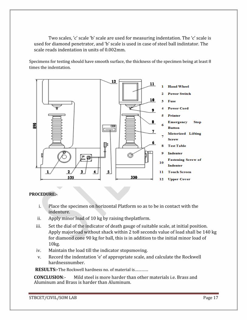
Two scales, ’c’ scale ‘b’ scale are used for measuring indentation. The ‘c’ scale is
used for diamond penetrator, and ‘b’ scale is used in case of steel ball indintator. The scale reads indentation in units of 0.002mm.
Specimens for testing should have smooth surface, the thickness of the specimen being at least 8
times the indentation.
PROCEDURE:-
i. Place the specimen on horizontal Platform so as to be in contact with the
indenture.
ii. Apply minor load of 10 kg by raising theplatform.
iii. Set the dial of the indicator of death gauge of suitable scale, at initial position. Apply majorload without shack within 2 to8 seconds value of load shall be 140 kg for diamond cone 90 kg for ball, this is in addition to the initial minor load of 10kg.
iv. Maintain the load till the indicator stopsmoving.
v. Record the indentation ‘e’ of appropriate scale, and calculate the Rockwell hardnessnumber.
RESULTS:-The Rockwell hardness no. of material is…………
CONCLUSION:- Mild steel is more harder than other materials i.e. Brass and Aluminum and Brass is harder than Aluminum.

STBCET/CIVIL/SOM LAB Page 18
EXPARIMENT NO- VI
IMPACT TEST ON METALS
AIM:-To conduct following impact test on metals.
Izod impact test b) Charpy impact test
APPARATUS:-
a) Impact testing machines b) Vernier caliper c) Scale
d) Standard izod and Charpy
THEORY:- The purpose of the test is to study the toughness of the materials. Toughness means the ability of the materials to absorb energy during plastic deformation when subjected to suddenly applied loads.
IMPACT STRENGTH:-
a) It is the resistance of the materials to shock or suddenly applied loads. It is equal to
the work performed in breading a specimen in a testing machines. Brittle materials
have low toughness. Since they have only small plastic deformation before failure.
Thus they absorb very little energy before failure andso are dangerous if used in
structures. Ductile materials absorb considerably energy before they break and so
are comparatively tougher. Thus ductile materials have greater resistance to
shockloading.
b) Other test such as tensile test, compression test etc. are conducted using gradually
apply loads. In practice we come across some loads which are suddenly applied. The
stress induced due to impact load is higher than those in case of gradually applied
loads. Thus structural member, which is safe to bear gradually applied loads may fail
under impact loads. Due to development of higher stresses impact may be in tension
or compression or shear or in bending.
c) The impact strength also depends on temperatures the strength at sub zero
temperature and at very high temperatures is required in somecases.
d)Impact test are based on following principles:
The amount of energy absorbed bymaterials before breaking under impact loading
depends on the nature of themetals.

STBCET/CIVIL/SOM LAB Page 19
DESCRIPTION OF THE MACHINES:-
The testing machines consist of heavy frame with heavy pendulum weight
supported at top of the frame. The pendulum can be clamped at a certain height
above the specimen and released for striking. The striking energy should be 16.56
kgm. The energy is read on a circular scale at top and which pointermoves as the
pendulum move. The scale is marked on both sides of centers, so as to read energy of
rise of pendulum on either of thespecimen.
IZOD TEST:-
The specimen is a square rod 10mmx 10 mm x 75mm long as shown in fig A. V
notch is made at 28mm from one end. Depth of notch is 2mm and the internal
angle is 45. With a route radius of 0 to 5 mm the specimen is fixed in advice with
the notch facing the hammer blow and level with and parallel to the top face of
vice. With top at 28 mm from the vice.
As per IS – 1598- 1977 the weight of the base and its foundation shell be at least 40
times the weight of the hammer. The plain of swing of hammer shall be
perpendicular to the vice.
The distance between base of notch and the point of specimen hit by hammer shall
be 22mm (i.e. 6mm for top ).
The angle of tip of hammer shall be 75and the angle between normal to the
specimen and the undersigned face of hammer at striking point shall be 10.
The energy absorb is is the initial energy of the hammer before striking minus final energy
remaining in in the hammer after it breaks the specimen as indicated by rise of the hammer by
swinging to other side.
STBCET/CIVIL/SOM LAB Page 20
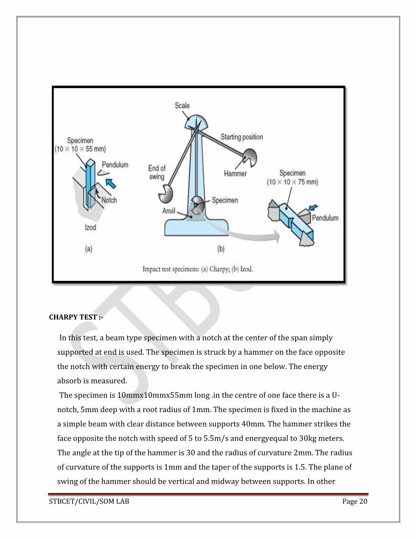
CHARPY TEST :-
In this test, a beam type specimen with a notch at the center of the span simply
supported at end is used. The specimen is struck by a hammer on the face opposite
the notch with certain energy to break the specimen in one below. The energy
absorb is measured.
The specimen is 10mmx10mmx55mm long .in the centre of one face there is a U-
notch, 5mm deep with a root radius of 1mm. The specimen is fixed in the machine as
a simple beam with clear distance between supports 40mm. The hammer strikes the
face opposite the notch with speed of 5 to 5.5m/s and energyequal to 30kg meters.
The angle at the tip of the hammer is 30 and the radius of curvature 2mm. The radius
of curvature of the supports is 1mm and the taper of the supports is 1.5. The plane of
swing of the hammer should be vertical and midway between supports. In other

STBCET/CIVIL/SOM LAB Page 21
respects the operation of the machine is similar to izod machine.
DESCRIPTION OF SPECIMEN:-
a. IZOD TEST: Test specimen 10mmX10mmX75mm long with a V-notch of
450,2mm deep and a root radius of 0.25mm at a distance of 28mm from one end. Notch should be at right angle to the longitudinal axis ofspecimen.
b. CHARPY TEST: Test specimen 10mmX10mmX55mm long with a U-notch at 27.5mm fromends, 5mm deep with roots radius 1mm. Axis of notch should be at right angles longitudinal axis of specimen.
PROCEDURE:-
A. IZODTEST:
1. Fix the pendulum weight with a flat striking surface. Bring it up andclamp.
2. Fix the specimen F izod test in the vice at the base with the notch facing the blow of hammer and at a distance of 28mm from top with the plane of symmetry in the same plane as of top of vice,in this position the pendulum will strike at 6mm from top (22mm fromnotch)
3. Adjust the pointer on the scale tozero.
4. Release the pendulum from theclamp.
5. The pendulum will strike the specimen and brake it, and swing to the other side
up due To some energy still left .after the pendulum rises to the highest point on
other side, the Pointer on the scale will read the energy absorbed by thespecimen.
STBCET/CIVIL/SOM LAB Page 22
B) Charpy Test:
1. Fix the hammer used for Charpy Test. Bring it up to ensure energy of 30 kg meters andclamp.
2. Place the specimen for Charpy test as described in above squarely against supports with notch on opposite side of the hammer blow the plane of symmetry of the notch should be in the plane of swing of thehammer.
3. Adjust the scale tozero
4. Release the hammer from theclamp
5. The hammer will break the specimen and will rise on the other side and come back. Note down the reading on the scale at the time of highest rise on other side. It indicates the impact strength of charpytest.
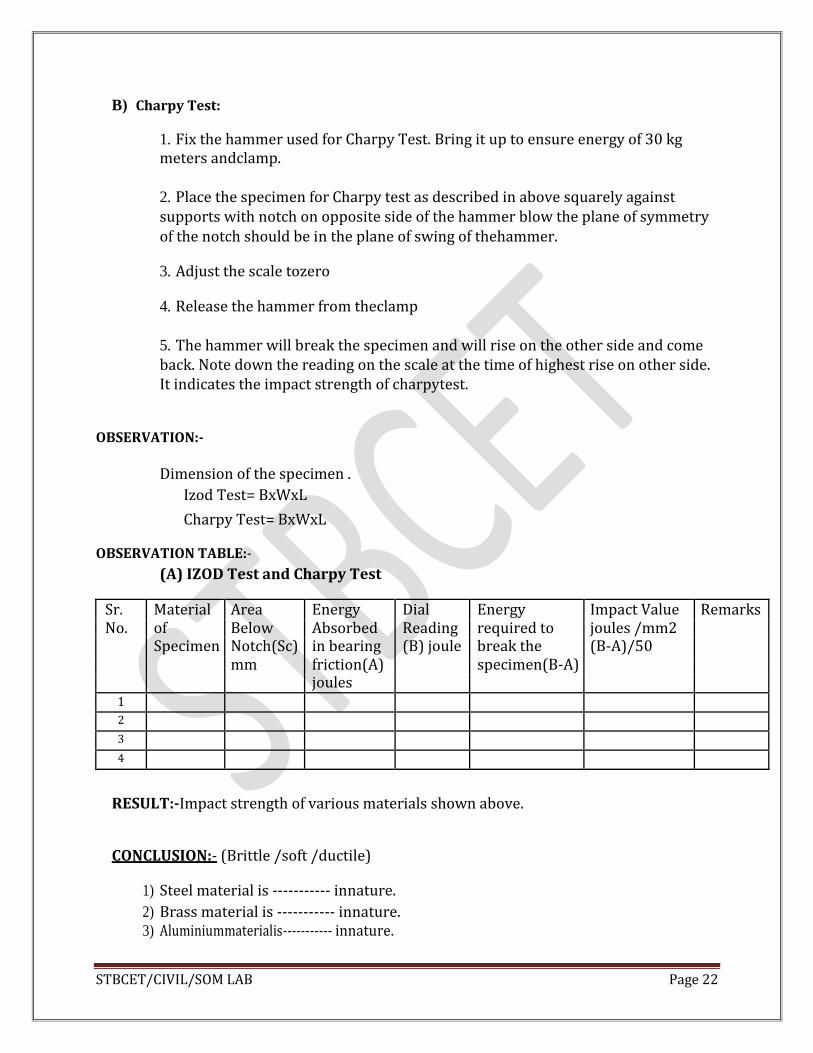
OBSERVATION:-
Dimension of the specimen .
Izod Test= BxWxL
Charpy Test= BxWxL
OBSERVATION TABLE:-
(A) IZOD Test and Charpy Test
Sr. Material Area Energy Dial Energy Impact Value Remarks No. of Below Absorbed Reading required to joules /mm2
Specimen Notch(Sc) in bearing (B) joule break the (B-A)/50
mm friction(A) specimen(B-A)
joules
1
2
3
4
RESULT:-Impact strength of various materials shown above.
CONCLUSION:- (Brittle /soft /ductile)
1) Steel material is ----------- innature.
2) Brass material is ----------- innature. 3) Aluminiummaterialis----------- innature.
STBCET/CIVIL/SOM LAB Page 23
EXPERIMENT NO.VII
TORSION TEST ON MILD STEEL BAR
AIM:-To conduct torsion test on mild steel bar.
APPARATUS:-
(a) Torsion testingmachine
(b) Vernier caliper
(c) Scale
THEORY:-
The purpose of the test is to determine the modulus of rigidity of metallic
material such as steel, cast iron of aluminum. This property is useful in design of machine members subjected to torsion such as shaft, helical springetc.
Torsion is the twisting of a member, which is subjected to a twisting
moment by two equal and opposite couples.
In this test the twisting moment is applied to a wire with diameter less than 12.5 mm and to cylindrical bars or tubes or pipes.
(a) For testing wires in torsion test, the ends of specimen are gripped in clamps. One of the ends is fixed and other end is rotated until the specimen breaks. The number of turns of rotation is counted by a revolution counter. The machine can be handoperated.
(b) For testing bars of larger diameter power operated machine is used. This machine consist of a straining unit which applied torque to one end of a specimen the other end being fixed and a pendulum weight unit which comprises of lever which transmits the torque from the fixed end of the specimen to dial indicator. At the end where the strain is applied, scale to measure angle of twist isprovided.
The angular twist is the torsional deformation.
Let T=Torque N mm.
L= Gauge length of specimen in mm to which torsional torque is applied.
= Angular deformation in radians
= Angular deformation for that length in radians.
STBCET/CIVIL/SOM LAB Page 24
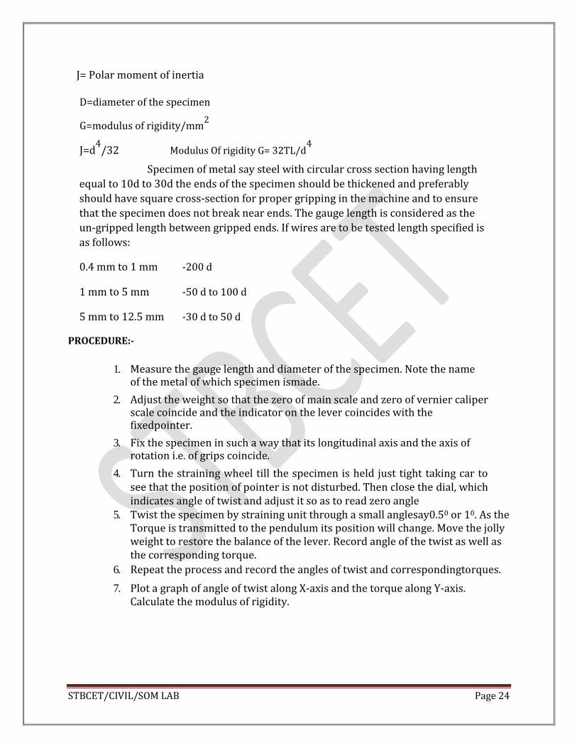
J= Polar moment of inertia
D=diameter of the specimen
G=modulus of rigidity/mm2
J=d4
/32 Modulus Of rigidity G= 32TL/d4
Specimen of metal say steel with circular cross section having length
equal to 10d to 30d the ends of the specimen should be thickened and preferably
should have square cross-section for proper gripping in the machine and to ensure
that the specimen does not break near ends. The gauge length is considered as the
un-gripped length between gripped ends. If wires are to be tested length specified is
as follows:
0.4 mm to 1 mm -200 d
1 mm to 5 mm -50 d to 100 d
5 mm to 12.5 mm -30 d to 50 d
PROCEDURE:-
1. Measure the gauge length and diameter of the specimen. Note the name
of the metal of which specimen ismade.
2. Adjust the weight so that the zero of main scale and zero of vernier caliper scale coincide and the indicator on the lever coincides with the fixedpointer.
3. Fix the specimen in such a way that its longitudinal axis and the axis of rotation i.e. of grips coincide.
4. Turn the straining wheel till the specimen is held just tight taking car to see that the position of pointer is not disturbed. Then close the dial, which indicates angle of twist and adjust it so as to read zero angle
5. Twist the specimen by straining unit through a small anglesay0.50 or 10. As the Torque is transmitted to the pendulum its position will change. Move the jolly weight to restore the balance of the lever. Record angle of the twist as well as the corresponding torque.
6. Repeat the process and record the angles of twist and correspondingtorques.
7. Plot a graph of angle of twist along X-axis and the torque along Y-axis. Calculate the modulus of rigidity.

STBCET/CIVIL/SOM LAB Page 25
OBSERVATIONS AND CALCULATIONS:-
1. Material of the specimen =-----------
2. Diameter=D=----------mm
3. Guage length=L=----------mm
OBSERVATION TABLE:
CALCULATION:-
Plot a graph of ɸ vs. T, take two points[x1,y1 and x2,y2]
T/ɸ =(y2-y1/x2-x1) x 180/π
G=---------- N/mm2
REMARKS:-
The modulus of rigidity ‘G’ of the specimen of the metal=-------N/mm2
Sr. No Angle of twist degree
Torque T N- mm
Sr. No Angle of twist degree
Torque T kg mm
1 2 3 1 2 3
1 6
2 7
3 8
4 9
5 10
J= Polar M.I=πd4/ 32 = ________ mm
4

STBCET/CIVIL/SOM LAB Page 26
EXPERIMENT NO.VIII
BENDING TEST ON TIMBER
AIM:- To conduct static bending test on timber, to study its behavior when subjected to bending up to failure and to find its modulus of elasticity and modulus of rupture.
APPARATUS:-
1. Universal testingmachine
2. Deflectometer to measure deflection of thebeam
3. Vernier scale, timber specimen
THEORY:-
The purpose of the static bending test on timber is to determine modulus of elasticity and modulus of rupture i.e. (extreme fiber states at maximum load) as well as maximum fiber stress in bending at the limit of proportionality.
NECESSITY OF DETERMINING THE ABOVE PARAMETER:-
1. As for any other modulus of structure, for design of timber, structures, the
knowledge of extreme stress is necessary. We can obtain this value by static bendingtest.
2. The knowledge of modulus of elasticity is also necessary to know the class of the timber as it is classified in 3 groups namely group A, B and C on the basis of modulus ofelasticity.
3. The static bending test is also conducted to determine the resistance of the timber in the form of beam.
PROCEDURE:-
The test is conducted on the timber sample in the form of beam centrally loaded
tested to failure. As the properties of fluid are influenced by moisture content and various
defects such as knots, splits, cross grains, etc for comparing test results the test has to be
conducted on a specimen at a certain standard moisture content and on specimen without
any defect and for straight grainsstandard moisture content the
specimenisbroughttoconstantweightbystagesundercontrolledconditionsat27°±2
°Ctempera
tureand65% ± 5% relative humidity as to bring the moisture content to about 12% test are
conducted in such a way as not to cause any large change in moisture content. Mount the

STBCET/CIVIL/SOM LAB Page 27
mm
specimen in the rig such that the distance between centers of support i.e. the span is 50 cm
and the load can be supplied centrally through the loading block as shown in figure.
Provide the thin metal plates between the loading block and specimen. The test is carried
out as follows.
1. Fix the deflectometer so as to measure the deflection at the neutral axis i.e. at the mid
depth at mid span.
2. Apply load gradually and continuously in such a way that the movable head of the testing
machine moves at a constant rate of 2.5mm/min.
3. Measure the deflection of the neutral axis at the mid span correct up to 0.002 mm, at suitable interval of load of up tofailure.
4. Record the load and deflection at the first failure, maximum load and points of sudden
changes in deflection andload. 5. Record the nature of failure whether simple tensions, cross strain tension,
splinteringtension, failure at compression or horizontal shearfailure.
OBSERVATIONS:-
1. Dimensions of specimen
A) Length ofspecimen(L)= mm
B) Breadth ofspecimen(b)= mm
C) Depth ofspecimen(h)= mm
D) Moment of inertia (a) atneutral axis= mm4
E) Species of timber = teak/ haldu/ mango/ devdar / anyother. 2. Table of observation of load anddeflection
SR NO Load in N Deflection in mm
3. Draw a load deflectioncurve.
4. Let W= load in kg at limit of proportionality i.e. upto which load deflection curve is
Straight line.
W’- Maximum load δ= cm
STBCET/CIVIL/SOM LAB Page 28
5. Modulus of elasticity = E =WL3/ 4 δ bh3 = ____---------- N/mm2
6. Modulus of rupture = R = 3W’L/2bh2= -------------- N/ mm2
7. Fiber stress at limit of proportionality (fb) = 3WL/2bh2=-------------N/mm2
8. Nature of failure = simple tension / cross grains tension/failure at compression /horizontal shear failure.
IS REQUIREMENTS:-
As per IS 883-1970 timber species are classified in three groups
Group A - modulus of elasticity more than 12.6 N/mm2
Group B - modulus of elasticity between 9.8 to 12.6 N/mm2
Group C - modulus of elasticity between 5.6 to 9.8 N/mm2
RESULTS:-
Modulus of elasticityE = N/mm2
Modulus of ruptureR = N/mm2 Fiber stress at proportionalitylimit = N/mm2
CONCLUSION:-
As the modulus of elasticity is ----------N/mm2, the sample is classified in group-----------.
STBCET/CIVIL/SOM LAB Page 29
EXPERIMENT NO.IX
COMPRESSIVE STRENGTH OF BURNT CLAY BUILDING BRICKS
(IS 1077-1976)
AIM :-
To determine compressive strength of burnt clay building bricks.
APPARATUS:-A compression testing machine, scale, plywood cover, etc.
THEORY:-
Bricks are mostly subjected to compression and rarely to tension. The usual
crushing strength ofcommon hand moulded well burnt bricks is @ 5 to 10
N/mm2 varying according to the nature ofpreparationof clay pressed and
machine moulded bricks made of thoroughly pugged clay are much stronger than
common hand moulded bricks made from carelessly prepared clay.
In all the brick walls the compressive strength of bricks decides the thickness of
walls hence it is necessary to test the compressive strength of the bricks.
PROCEDURE:-
1. Take 5 bricks and remove unevenness observed in the bed face to provide two
smooth and parallel faces bygrinding.
2. Immersed the bricks in water at room temperature for 24hours
3. Remove the specimen and drain out any surplus moisture at roomtemperature
4. Fill the frog (where provided) and all voids in the bed face flush with cement mortar ( 1 cement, 1 clean coarse sand of grade 3 mm anddown.)
5. Store under the damp jute box for 24hours
6. Remove and wipe out traces of moisture and place the specimen with flat faces horizontal and mortar filled few facing upwards between two plywood sheet each 3 mm thickness and carefully centered between plates of testingmachine.
7. Apply load axially of uniformrate. 8. Note down the load at failure. That load shall be the maximum load at which the
specimen fails to produce any further increase in the indicator reading on the testingmachine.

STBCET/CIVIL/SOM LAB Page 30
NOTE:-
In place of plywood sheets plaster of Paris may be used to ensure a uniform surface of application of load.
OBSERVATION TABLE:-
CLASS DESIGNATION AVERAGE COMP.
MINIMUM N/mm2
STRENGTH MAXIMUM 2
N/m 350 35 40
300 30 35
250 25 30
200 20 25
175 17.5 20
150 15 17.5
125 12.5 15
100 10 12.5
75 7.5 10
35 3.5 7.5
CONCLUSION:-The bricks can be / cannot be used as a constructional material.

STBCET/CIVIL/SOM LAB Page 31
EXPERIMENT NO.X
ABSORPTION TEST ON BUILDING BRICKS.
AIM:-To determine the water absorption of burnt clay building Bricks.
APPARATUS: - A sensitive balance capable of weighing within 0.1 percent of the mass of the specimen and a ventilated Oven. THEORY:-Bricks for external use must be capable of preventing rain water from passing through them to the inside the walls of reasonable thickness. A good brick should absorb water maximum 1th of the weight of the brick.
PROCEDURE:-
1. Take 5 Bricks and dry in a ventilated oven at a temperature of 1050cto1150c
till
it attains substantially constantmass.
2. Cool the specimen to room temperature and obtain its weight (w1). Specimen warm to touch shall not be used for thepurpose.
3. Immerse completely dry specimen in clean water at a temperature of 270 c ± 20c for 24 hours.
4. Remove the specimen and wipe out any traces of water with a damp cloth and weigh the specimen (W2).
5. Complete the weighing within three minutes after the specimen has been removed fromwater.
6. Water absorption , percent by mass, after 24 hours, % water absorption is given byformula
= W2 – W1 / W1 X 100
OBSEVATION TABLE:-
Sample No. Dry weight of the Brick W1
Weight of the wet Brick W2
% water absorption = W2 – W1 / W1 X 100
Remark
01
02
03
04
05

STBCET/CIVIL/SOM LAB Page 32
I.S. Requirement:-
After immersion in cold water for 24 hours , the average water absorption of the
bricks shall not be more than 20% by weight up to class 125 and 15% by weight
for higher classes.
CONCLUSION:-The bricks can be / cannot be used as a constructional material