density based tra c management using iot
TRANSCRIPT
Density Based Traffic ManagementUsing IoT
K.Lalitha1, Dr. M. Pounambal2,1Assistant Professor,Dept of CSSE,SVEC
2Vellore Institute of Technology(Vellore Campus )
October 12, 2018
Abstract
The Internet of Things (IoT) plays an important rolein developing many applications, which could be sometimesreal-world entities. The main objective of the project is toalter the time at the signal based on a number of vehicles.Depending on the number of vehicles passing through theIR sensor the time gets varied. If the number of vehicles ismore it allocates more time so that there would be furtherdecreased in a traffic jam. Microcontroller automatically ad-justs the time gap between two successive intervals of time,which is commonly known as dynamic time adjustment sys-tem or dynamic traffic signal system based on density.Thewebpage which must give a continuous update so that it canhandle traffic smoothly.
Key Words::Internet of Things, IR Module, TrafficManagement.
1 Introduction
Internet of things (IoT) is, as for, contemporary functionality andbest productiveness by uninterrupted connection of devices. Kevin
1
International Journal of Pure and Applied MathematicsVolume 120 No. 6 2018, 781-792ISSN: 1314-3395 (on-line version)url: http://www.acadpubl.eu/hub/Special Issue http://www.acadpubl.eu/hub/
781
Ashton first proposed the term internet of things in 1999. Inter-net of Things is the future that transforms the real world physicalobjects into well-informed virtual objects. The lack of architec-ture standards for the industrial and connectivity in the IoT is amajor threat.The reference frameworks for the Internet of Thingsare uniquely identifiable objects and their virtual representations.Itconnects heterogeneous communities. Industrial Internet and In-dustry 4.0 are the alternative names of IoT in North America andEurope respectively. The properties of the Internet of Things aredominance and attributes. IOT devices are inherently connected,we away from interacting with them and are commonly used forcollecting and analyzing personal data. The Density Based trans-port system plays a major role to reduce the traveling time, waitingtime, traffic conditions at a particular area, weather conditions, etc.Secondly, to monitor traffic signs, to monition the vehicle driver andcontrol or disallow certain actions, traffic sign recognition is used.To support and disburden the driver, also driving safety and com-fort, a fast real-time and robust automatic traffic sign detectionand recognition is used. The automatic recognition of traffic signsis important for automated driver assistance system to provide thedriver various information for safe and efficient navigation.But thetraffic sign identification with respect to various background view-ing conditions is a challenging task. Facilitate transportation diffi-culties, reduce traffic volume waiting time, understate overall traveltime, effieciency,optimize the safety of cars and elaborate the bene-fits in economic ,health and environmental spheres can be upgradedby conventional traffic system. To improve time management andto overcome many flaws, the simple, low-cost andreal-time smarttraffic light control system has made its implementation. To con-trol various operations, to monitor the traffic volume, to calculatethe density flow thru infrared sensors and to change the lightingmodulation slots accordingly the microcontroller based system hasto be used. Let us have a brief survey of the volume of vehiclesthat the number of vehicular purchasing is maximizing. Privatevehicle sales are believed to be largely responsible for the increasein registration of vehicles. In 2014 in India, the total registrationsstood at 1.94 crores. The highest vehicle registration in India, Ut-tar Pradesh, with 24.38 lakh number of vehicle registrations hadbeen recorded in 2015. Maharashtra holds second place with 19.91
2
International Journal of Pure and Applied Mathematics Special Issue
782
lakh number of registrations followed by 15.15 lakhs in Karnataka,which holds third. There is an expectation that countrys vehiclepopulation could touch at least 35 crore number of vehicles fromthe present 18.6 crore number of vehicles in next 20-30 years. Sogoverning of vehicles to manage the traffic is definitely a crucialone. The designed system consists of various subsystems such asan Infrared sensor, low power ,comparators and Energy EfficientMicrocontroller and Here we focused on the development of intelli-gent traffic system i.e. signal light controller using IR sensors andMicrocontroller. The limitation in a traffic control system in nor-mal vehicle detection is that they have to be controlled only by thehuman [4]. The Density-based traffic management system providesan easy manner to measure the traffic snarl-up data final resultsin more efficacious control. Major vantage of utilizing the density-based control through the infrared sensor is that it is beneficial toboth environment and economy [1]. The overall efficiency, accuracyand the capability of real-time flow control can be improved by thissystem. Each sensor has the capability of sensing the traffic densityand litigate the data through microcontroller for performance. Ateach lane, each sensor is positioned at a specific calculated locationover the line. The sensors are linked to the microcontroller via awired connection. The result will be envisioned in the form of anumber of seconds the signal has to beam.
2 ANALYSIS
In the analysis phase, it has been specifying the existing system andthe proposed system. The analysis phase also focuses on providingdetails regarding both hardware and software requirements.
2.1 INDUCTIVE LOOP SYSTEM
The principle of Inductive loop detection system works with theprinciple that one or more turns of insulated wire are placed inthe shoal exscind in the route. A lead-in wire runs from roadsidepull box to the electronic unit and the controller located in thecontroller storage system. The induction of the wire is changedwhen a vehicle passes over the loop or stops. Obviously, there willbe a change in the frequency. The controller will be receiving the
3
International Journal of Pure and Applied Mathematics Special Issue
783

signal indication, which is the frequency change in the electronicunit. This inductive loop detection system is useful in getting thevehicle presence, passageway, occupancy and even the number ofvehicles passing via a specified region. But there are few limitationsin this system. The poor dependability of system due to improperconnectivity made in the pull boxes and due to the diligence ofsealant over the cutoff of the road. If this system is enforced in thepoor pavement or where delving of the roads is frequent then theproblem of dependability will be worsened.
2.2 VIDEO ANALYSIS
Video analysis comprises of a smart camera, which contains sensors,a processing unit,and a communication unit. The continuous trafficwill be supervised with the help of smart cameras. The video, whichis captured, is compacted to reduce the transmittal bandwidth.The raw data will be collected via video analysis. Traffic statisticswill be done by this statistical data. These stats include averagespeed of vehicles, the frequency of vehicles and the lane occupancy.Following are the problems consociated with video analysis- 1. Thesystem gets impacted in case of heavy rains or fog. 2. The totaltoll of the system will be quite high. 3. Night time surveillancerequires thorough street light arrangement.
3 SYSTEM DESIGN
The Density Based Traffic Management System consists of mainlyMicrocontroller, which is the heart of the system, IR Sensors placedon top of every lane just far away from signal lights, Ethernet shieldto intercommunicate with the website via the internet. IR sensorsare arranged on each lane, above the road at a certain distance, say500 m (each side of the junction). These IR sensors are connectedto one microcontroller. The IR sensor collects the data that hascrossed it and transfers it to the microcontroller. It will analyzewhich lane has more density and the green signal will be assignedto that specified lane which has much traffic [4]. The signal lightsare connected to the micro controller, which reflects density in theform of green light. More time slice will be assigned to a particular
4
International Journal of Pure and Applied Mathematics Special Issue
784
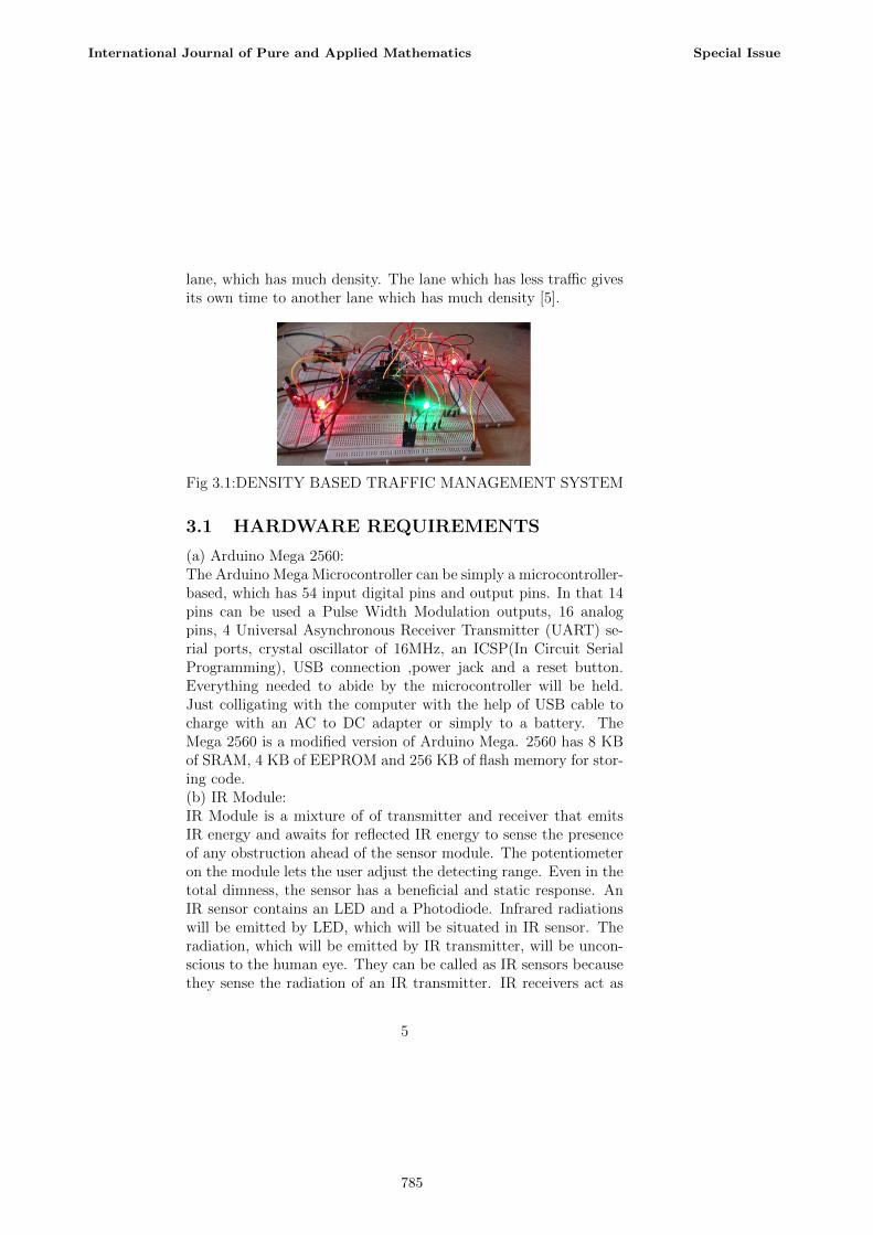
lane, which has much density. The lane which has less traffic givesits own time to another lane which has much density [5].
Fig 3.1:DENSITY BASED TRAFFIC MANAGEMENT SYSTEM
3.1 HARDWARE REQUIREMENTS
(a) Arduino Mega 2560:The Arduino Mega Microcontroller can be simply a microcontroller-based, which has 54 input digital pins and output pins. In that 14pins can be used a Pulse Width Modulation outputs, 16 analogpins, 4 Universal Asynchronous Receiver Transmitter (UART) se-rial ports, crystal oscillator of 16MHz, an ICSP(In Circuit SerialProgramming), USB connection ,power jack and a reset button.Everything needed to abide by the microcontroller will be held.Just colligating with the computer with the help of USB cable tocharge with an AC to DC adapter or simply to a battery. TheMega 2560 is a modified version of Arduino Mega. 2560 has 8 KBof SRAM, 4 KB of EEPROM and 256 KB of flash memory for stor-ing code.(b) IR Module:IR Module is a mixture of of transmitter and receiver that emitsIR energy and awaits for reflected IR energy to sense the presenceof any obstruction ahead of the sensor module. The potentiometeron the module lets the user adjust the detecting range. Even in thetotal dimness, the sensor has a beneficial and static response. AnIR sensor contains an LED and a Photodiode. Infrared radiationswill be emitted by LED, which will be situated in IR sensor. Theradiation, which will be emitted by IR transmitter, will be uncon-scious to the human eye. They can be called as IR sensors becausethey sense the radiation of an IR transmitter. IR receivers act as
5
International Journal of Pure and Applied Mathematics Special Issue
785

phototransistors and photodiode. Normal photodiodes detect onlyinfrared radiation. But IR Photodiodes are different. When IRtransmitter emits radiation it hits the object and a part of the ra-diation will be reflected back to the IR receiver. Depending on theintensity to the receiverthe result of the sensor will be determined.(c) Light Emitting Diodes:The main component of the system is Arduino ATmega Microcon-troller, could also be stated as the heart of the system. The mi-crocontroller considers the input, which will be given from variousinterlinked devices, and externalizes the result which is responsiblefor the final output. Here, the microcontroller receives the numberof vehicles that pass over, from the IR sensors, calculates the timeslice respectively and exhibits the turnout. The count will be in-cremented whenever a vehicle crosses over from the IR sensor. IRsensor is placed over every lane, a bit far from the signal lights. SoIR sensors consider every vehicles pass over as input and send it tothe microcontroller, which computes the time slice for every lane,with respect to a number of vehicles and cast the output in theform of signal lights. To connect to the internet, Ethernet Shield isused.(d) Ethernet Shield:The Arduino Ethernet Shield modifies the Arduino to transfer datato anyplace globally with an internet connectivity. We can use it toreceive notifications on the website like message arrival, bell ring-ing, etc.; remotely. The shield appropriates an unending amountof data by allowing to associate with any project to the internet.The shield will be attributed to an IP address and a MAC address.The MAC address is a unique identifier for each device, worldwide.Latest Ethernet Shields come with a label suggesting MAC addresswhich must be used. In olden shields, there would not be any kindof MAC address but the same address would not be used. GenuineIP address looks at the configuration of the network. A recommen-dation could be a DHCP usage with the IP to the shield. It can alsobe specified with a network gateway. The upcoming shields also in-clude resetting controller which assures that the Ethernet moduleis rightly reset on power-up. Old versions were not simpatico withthe Mega and manually reset after power-up.
6
International Journal of Pure and Applied Mathematics Special Issue
786
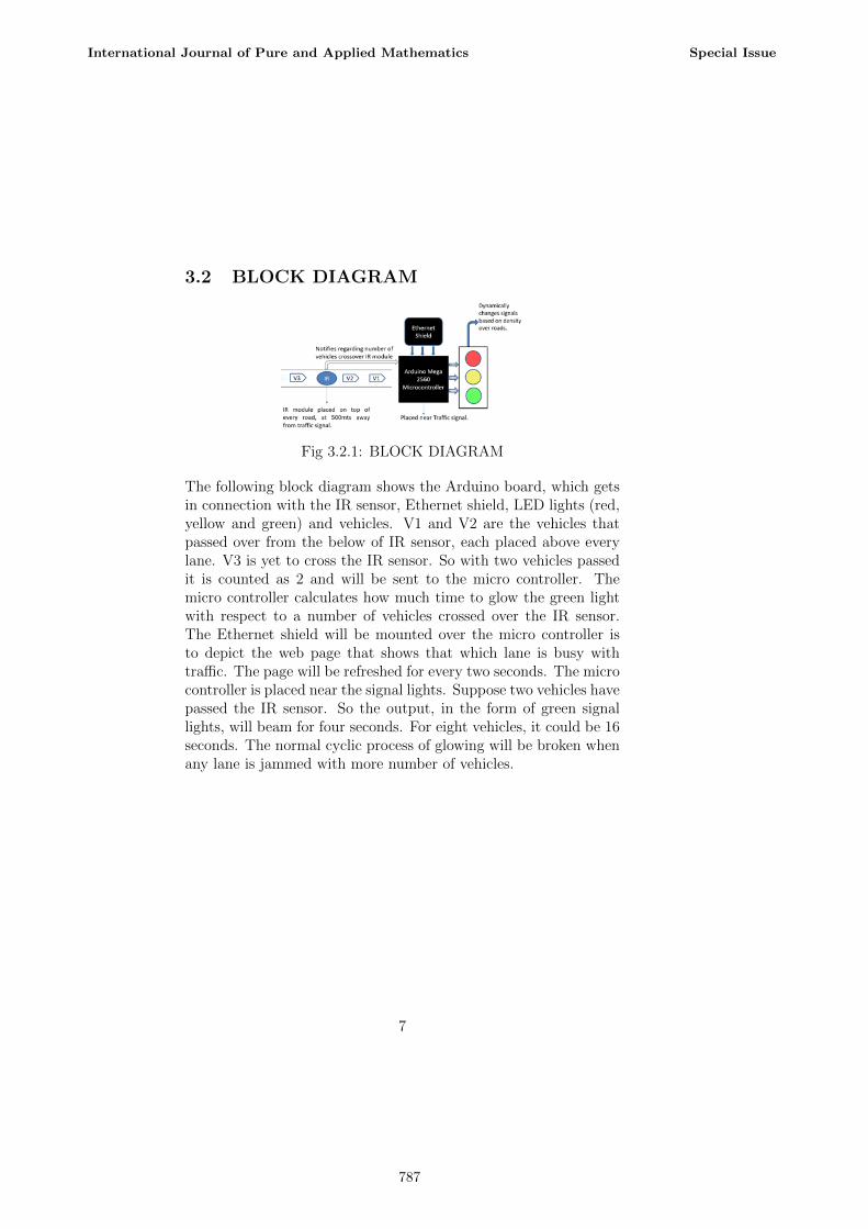
3.2 BLOCK DIAGRAM
Fig 3.2.1: BLOCK DIAGRAM
The following block diagram shows the Arduino board, which getsin connection with the IR sensor, Ethernet shield, LED lights (red,yellow and green) and vehicles. V1 and V2 are the vehicles thatpassed over from the below of IR sensor, each placed above everylane. V3 is yet to cross the IR sensor. So with two vehicles passedit is counted as 2 and will be sent to the micro controller. Themicro controller calculates how much time to glow the green lightwith respect to a number of vehicles crossed over the IR sensor.The Ethernet shield will be mounted over the micro controller isto depict the web page that shows that which lane is busy withtraffic. The page will be refreshed for every two seconds. The microcontroller is placed near the signal lights. Suppose two vehicles havepassed the IR sensor. So the output, in the form of green signallights, will beam for four seconds. For eight vehicles, it could be 16seconds. The normal cyclic process of glowing will be broken whenany lane is jammed with more number of vehicles.
7
International Journal of Pure and Applied Mathematics Special Issue
787
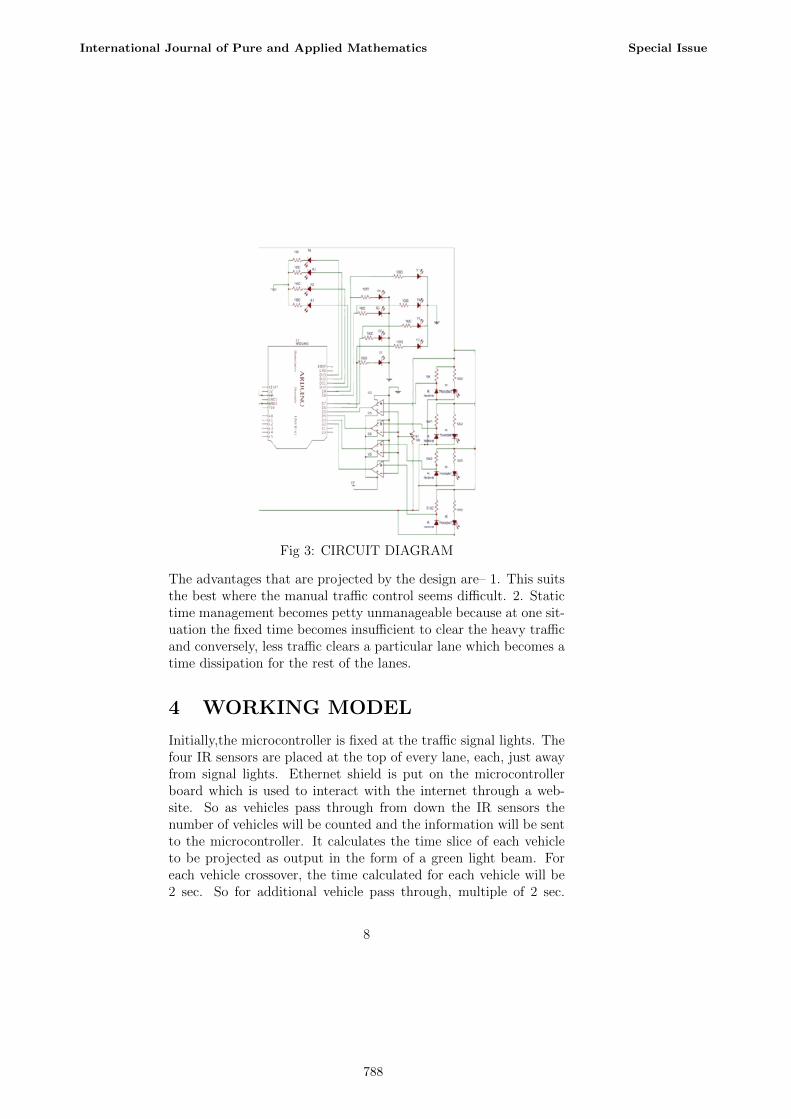
Fig 3: CIRCUIT DIAGRAM
The advantages that are projected by the design are– 1. This suitsthe best where the manual traffic control seems difficult. 2. Statictime management becomes petty unmanageable because at one sit-uation the fixed time becomes insufficient to clear the heavy trafficand conversely, less traffic clears a particular lane which becomes atime dissipation for the rest of the lanes.
4 WORKING MODEL
Initially,the microcontroller is fixed at the traffic signal lights. Thefour IR sensors are placed at the top of every lane, each, just awayfrom signal lights. Ethernet shield is put on the microcontrollerboard which is used to interact with the internet through a web-site. So as vehicles pass through from down the IR sensors thenumber of vehicles will be counted and the information will be sentto the microcontroller. It calculates the time slice of each vehicleto be projected as output in the form of a green light beam. Foreach vehicle crossover, the time calculated for each vehicle will be2 sec. So for additional vehicle pass through, multiple of 2 sec.
8
International Journal of Pure and Applied Mathematics Special Issue
788
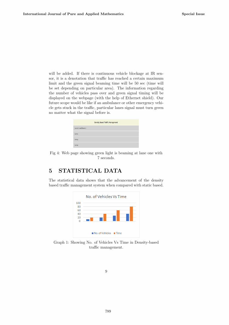
will be added. If there is continuous vehicle blockage at IR sen-sor, it is a denotation that traffic has reached a certain maximumlimit and the green signal beaming time will be 50 sec (time willbe set depending on particular area). The information regardingthe number of vehicles pass over and green signal timing will bedisplayed on the webpage (with the help of Ethernet shield). Ourfuture scope would be like if an ambulance or other emergency vehi-cle gets stuck in the traffic, particular lanes signal must turn greenno matter what the signal before is.
Fig 4: Web page showing green light is beaming at lane one with7 seconds.
5 STATISTICAL DATA
The statistical data shows that the advancement of the densitybased traffic management system when compared with static based.
Graph 1: Showing No. of Vehicles Vs Time in Density-basedtraffic management.
9
International Journal of Pure and Applied Mathematics Special Issue
789
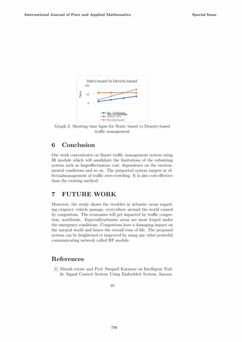
Graph 2: Showing time lapse for Static based vs Density-basedtraffic management
6 Conclusion
Our work concentrates on Smart traffic management system usingIR module which will annihilate the limitations of the subsistingsystem such as hugeeffectuation cost, dependence on the environ-mental conditions and so on. The purported system targets at ef-fectualmanagement of traffic over-crowding. It is also cost-effectivethan the existing method.
7 FUTURE WORK
Moreover, the study shows the troubles in urbanite areas regard-ing exigency vehicle passage, everywhere around the world causedby congestions. The economies will get impacted by traffic conges-tion, worldwide. Especiallyurbanite areas are most forged underthe emergency conditions. Congestions have a damaging impact onthe natural world and hence the overall tone of life. The proposedsystem can be heightened or improved by using any other powerfulcommunicating network called RF module.
References
[1] Dinesh rotate and Prof. Swapnil Karmore on Intelligent Traf-fic Signal Control System Using Embedded System, Innova-
10
International Journal of Pure and Applied Mathematics Special Issue
790
tive Systems Design And Engineering, ISSN 2222-1727 (paper)ISSN 2222-2871 (online), Vol. 3, No. 5, 2012.
[2] Shruthi K R and Vinodha K on Priority Based TrafficLights Controller Using Wireless Sensor Networks, Interna-tional Journal Of Electronics Signals And Systems (IJESS)ISSN: 2231- 5969, Vol-1 Iss-4, 2012
[3] Koushik Mandal, Arindam Sen, Abhijnan Chakraborty andSiuli Roy on Road Traffic Congestion Monitoring and Measure-ment using Active RFID and GSM Technology, IEEE — An-nual Conference on Intelligent Transportation Systems, 2011.
[4] VikramadityaDangi, AmolParab, KshitijPawar and S.SRathod on Image Processing Based Intelligent Traffic Con-troller, Undergraduate Academic Research Journal (UARJ),ISSN: 2278 1129, Vol-1, Iss-1, 2012.
[5] B. Prashanth Kumar, B. Karthik on Microcontroller basedtraffic light controller,Department of Electrical Engg.
[6] International Journal of Innovative Research in Science, Engi-neering,and Technology Volume 3, Issue 3, March 2014 DensityBased Traffic Signal System by K.Vidhya, A.BazilaBanu.
11
International Journal of Pure and Applied Mathematics Special Issue
791

792