demos traci on
DESCRIPTION
demostracion de la formula de capacidad portante mediante meyerhoffTRANSCRIPT
Theoretical Soil Mechanics. Karl TerzaghiCopyright © 1943 John Wiley & Sons, Inc.
CHAPTER VIn
BEARING CAPACITY
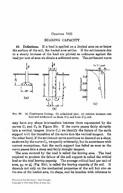
43. Definitions. If a load is applied on a limited area on or below the surface of the soil, the loaded area settles. If the settlements due to a steady increase of the load are plotted as ordinates against the load per unit of area we obtain a settlement curve. The settlement curve
lQ
I1r-I I /-2.8 -I
(a)
+ c: Q)
o.
Unit Load
Or-~=:::;'l==; :-,!'I=..D_ ..... , I Cz :
, 1
\1
~ Q1B ~ \ \ ..... .....
~O.3B
MB
(c)
C'2\ \ \ \
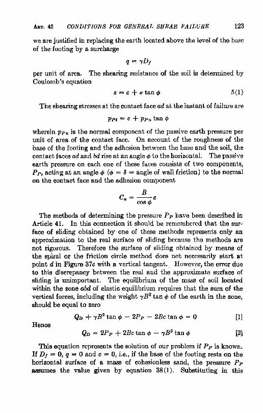
FIG. 36. (a) ContinuouB footing; (b) cylindrical pier; (c) relation between unit load and settlement on dense (C1) and loose (C2) Boil.
may have any shape intermediate between those represented by the curves C1 and C2 in Figure 36c. If the curve passes fairly abruptly into a vertical tangent (curve C1) we identify the failure of the earth support with the transition of the curve into the vertical tangent. On the other hand, if the settlement curve continues to descend on a slope, as shown by the curve C2, we specify arbitrarily, but in accordance with current conceptions, that the earth support has failed as soon as the curve passes into a steep and fairly straight tangent.
The area covered by the load is called the bearing area. The load required to produce the failure of the soil support is called the cr£tical load or the total bearing capacity. The average critical load per unit of area, qD or qb (Fig. 36c), is called the bearing capacity of the soil. It depends not only on the mechanical properties of the soil but also on the size of the loaded area, its shape, and its location with reference to
ART. 44 FAILURE BY LOCAL AND BY GENERAL SHEAR 119
the surface of the soil. In the following articles the investigation is limited to vertical loads acting on horizontal bearing areas.
H the load acts on a very long strip with a uniform width it is called a strip load in contrast to a load which acts on an area whose width is approximately equal to its length, such as a square, a rectangular, or a circular area. In engineering practice the load is transmitted to the bearing area by means of footings or piers. Figure 36a is a section through a footing. The length of a continuous footing is great compared to its width 2B whereas that of a spread footing is approximately equal to the width. A pier (Fig. 36b) is a cylindrical or a prismatic body of masonry whose horizontal dimensions are small compared to the depth D I of its base below the surface. The lower end of some piers is given the shape of a truncated cone whose base has a greater area than the section through the pier (belled-out caisson pier).
In the following investigations it is a.ssumed that the soil is homogeneous from the surface to a depth which is far below the level of the base of the footings or piers.
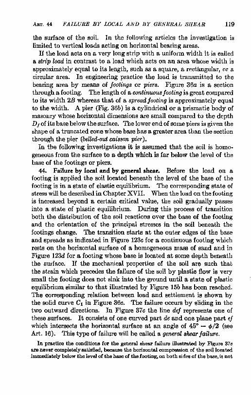
44. Failure by local and by general shear. Before the load on a footing is applied the soil located beneath the level of the base of the footing is in a state of elastic equilibrium. The corresponding state of stress will be described in Chapter XVII. When the load on the footing is increased beyond a certain critical value, the soil gradually passes into a state of plastic equilibrium. During this process of transition both the distribution of the soil reactions over the base of the footing and the orientation of the principal stresses in the soil beneath the footings change. The transition starts at the outer edges of the base and spreads as indicated in Figure 123c for a continuous footing which rests on the horizontal surface of a homogeneous mass of sand and in Figure 123d for a footing whose base is located at some depth beneath the surface. H the mechanical properties of the soil are such that the strain which precedes the failure of the soil by plastic flow is very small the footing does not sink into the ground until a state of plastic equilibrium similar to that illustrated by Figure 15b has been reached. The corresponding relation between load and settlement is shown by the solid curve C1 in Figure 36c. The failure occurs by sliding in the two outward directions. In Figure 37c the line def represents one of these surfaces. It consists of one curved part de and one plane part ef which intersects the horizontal surface at an angle of 45° - cf>/2 (see Art. 16). This type of failure will be called a general shear failure.
In practice the conditions for the general shear failure illustrated by Figure 37 c are never completely satisfied, because the horizontal compression of the 80illocated immediately below the level of the base of the footing, on both sides of the base, is not
120 BEARING CAPACITY ART. 44
great enough to produce the state of plastic equilibrium within the entire upper part of the zone aef. Therefore one has to expect a failure similar to that illustrated by Figure 37d. On account of inadequate lateral compression the shear failure occurs while the uppermost part of the zones of potential plastic equilibrium is still in a state of elastic equilibrium. If the surface of sliding cuts across a. mass of sand in a state of elastic equilibrium, it may intersect the free surface at a.ny angle intermediate between 45° - <1>/2 and 90°. (See Figures 17a and c and 70c.) In cohesive soils the surface of sliding terminates at the boundary of the zone of elastic equilibrium. In the proximity of the free surface of such soils one may find instead of a zone of shear a set of discontinuous tension cracks. In the theory of general shear failure these discrepancies between theory and rea.lity will be disregarded. The resulting error is unimportant.
On the other hand, if the mechanical properties of the soil are such that the plastic flow is preceded by a very important strain, the approach to the general shear failure is associated with a rapidly increasing settlement and the relation between load and settlement is approximately as indicated in Figure 36c by the dashed curve C2• The criterion for the failure of the soil support, represented by a conspicuous increase of the slope of the settlement curve, is satisfied before the failure spreads to the surface. Hence, this type of failure will be called local shear failure.
4S. Conditions for general shear failure of soil support of shallow, continuous footings. The term" shallow footing" is applied to footings whose width 2B is equal to or greater than the vertical distance D, between the surface of the ground and the base of the footing. If this condition is satisfied we can neglect the shearing resistance of the soil located above the level of the base of the footing. In other words we can replace the soil with a unit weight 1', located above this level, by a surcharge q = D/'Y per unit of area. This substitution simplifies the computations very considerably. The error is unimportant and on the safe side. On the other hand, if the depth D, is considerably greater than the width 2B (deep footings), it is necessary to take the shearing stresses in the soil located above the level of the base into consideration (see Art. 50).
If the soil located above the level of the base of a footing has been replaced by a surcharge, q per unit of area, the base of the footing represents a loaded strip with a uniform width 2B located on the horizontal surface of a semi-infinite mass. The state of plastic equilibrium produced by such a load is illustrated by Figure 15b. The figure is based on the assumption that the shearing stresses on the loaded area are equal to zero. In order to produce such a state of stress at the base of a continuous footing it would be necessary to eliminate completely the friction and the adhesion between the base and the soil. Figure 37 a has

ART. 45 CONDITIONS FOR GENERAL SHEAR FAILURB 121
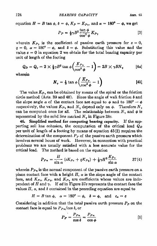
been plotted on the basis of the same assumption. The zone of plastic equilibrium represented in this figure by the area ffte1de can be subdivided into (I) a wedge-shaped zone located beneath the loaded strip, in which the major principal stresses are vertical, (II) two zones of radial shear, ade and bdelJ emanating from the outer edges of the loaded strip, whose boundaries intersect the horizontal at angles of
Smoofll perSf! (a)
!aug/soi/, Rot/gil bose
(b)
b 'i -,..l~~~L"1! ________ _
era lacer/ soil,
Rough base erna surcherrge
(c)
FIG. 37. Boundaries of zone of plastic flow after failure of earth support of continuous footings.
45° + cp/2 and 45° - cp/2, and (III) two passive Rankine zones. The dotted lines on the right-hand side of Figure 37a indicate the boundaries of the zones I to III at the instant of the failure of the soil support and the solid lines represent the same boundaries while the load sinks into the ground. The soil located within the central zone I spreads laterally and the section through this zone undergoes the distortion indicated in the figure.
If the load is transmitted onto the ground by means of a continuous
122 BEARING CAPACITY ART. 45
footing with a rough base as shown in Figure 37b, the tendency of the soil located within the zone I to spread is counteracted by the friction and adhesion between the soil and the base of the footing. On account of the existence of this resistance against lateral spreading the soil located immediately beneath the base of the footing remains permanently in a state of elastic equilibrium and the soil located within the central zone behaves as if it were a part of the sinking footing. The depth of this wedge-shaped body of soil remains practically unchanged. Yet the footing sinks. This process is only conceivable if the soil located just below point d moves vertically downward. This type of movement requires that the surface of sliding de through point d should start from a vertical tangent. The boundary ad of the zone of radial shear, ade, is also a surface of sliding. According to Article 7 the potential surfaces of sliding in an ideal plastic material intersect each other in every point of the zone of plastic equilibrium at an angle of 90° -,p. Therefore the boundary ad (Fig. 37b) must rise at an angle ,p to the horizontal, provided the friction and adhesion between the soil and the base of the footing suffice to prevent a sliding motion at the base. The right-hand side of this figure shows the deformation associated with the sinking of the footing. The sharp rise of the soil on both sides of the base of the footing has given rise to various speculations, and it has been referred to as edge action. It is nothing else but the visible manifestation of the existence of two zones of radial shear.
Trial computations have shown that the angle of base friction required to produce the state of plastic flow illustrated by Figure 37b is very much smaller than the angle of shearing resistance of the supporting soil. Hence, the lower boundary of the central zone beneath footings can always be assumed to rise at an angle ,p to the horizontal. However, theoretically, the slope angle of these boundaries may have any value 1/1 intermediate between ,p and 45° + ,p/2.
Whatever the slope angle of the boundaries may be, the footing cannot sink into the ground until the pressure exerted by the load onto the soil adjoining the inclined boundaries of zone I in Figure 37c becomes equal to the passive earth pressure. The passive earth pressure can be computed by means of one of the methods described in Chapter VII and the ultimate bearing capacity is determined by the condition that the sum of the vertical components of the forces which act on the soil located within the central zone I must be equal to zero.
To illustrate the procedure we compute the ultimate bearing capacity of a shallow continuous footing whose base is located at a depth D, below the horizontal surface of a mass of soil with a unit weight 'Y.
Figure 37c is a section through the footing. Since the footing is shallow
ART. 45 CONDITIONS FOR GENERAL SHEAR FAILURE 123
we are justified in replacing the earth located above the level of the base of the footing by a surcharge
q = -yD,
per unit of area. The shearing resistance of the soil is determined by Coulomb's equation
8 == C + utancp 5(1)
The shearing stresses at the contact face ad at the instant of failure are
PPI = C + PPn tan cf>
wherein PPn is the normal component of the passive earth pressure per unit of area of the contact face. On account of the roughness of the base of the footing and the adhesion between the base and the soil, the contact faces ad and bd rise at an angle cf> to the horizontal. The passive earth pressure on each one of these faces consists of two components, Pp, acting at an angle cp (cf> = a = angle of wall friction) to the normal on the contact face and the adhesion component
B Co = --c
cos cf>
The methods of determining the pressure Pp have been described in Article 41. In this connection it should be remembered that the surface of sliding obtained by one of these methods represents only an approximation to the real surface of sliding because the methods are not rigorous. Therefore the surface of sliding obtained by means of the spiral or the friction circle method does not necessarily start at point d in Figure 370 with a vertical tangent.. However, the error due to this discrepancy between the real and the approximate surface of sliding is unimportant. The equilibrium of the mass of soil located within the zone abd of elastic equilibrium requires that the sum of the vertical forces, including the weight -yB2 tan cp of the earth in the zone, should be equal to zero
QD + -yB2 tan cf> - 2Pp - 2Bc tan cp = 0 [1] Hence
QD = 2Pp + 2Bc tan cf> - 'YB2 tan cf> [2]
This equation represents the solution of our problem if Pp is known. If D, = 0, q = 0 and c = 0, i.e., if the base of the footing rests on the horizontal surface of a mass of cohesion less sand, the pressure Pp assumes the value given by equation 38(1). Substituting in this
124 BEARING CAPACITY ART. 45
equation H = B tan cp, ~ = cp, Kp = K py, and a = 1800 - t/J, we get
Pp = tyB2 tan cp Kp [3j cos2 cp y
wherein K py is the coefficient of passive earth pressure for c = 0, q = 0, a = 1800
- cp, and ~ = cp. Substituting this value and the value c = 0 in equation 2 we obtain for the total bearing capacity per unit of length of the footing
QD = Qy = 2 X t'YB2 tan cp (K~y - 1) = 2B X 'YBN.., [4a] cos t/J
wherein
N..,=ttancp(K~y -1) cos cp
[4b]
The value K py can be obtained by means of the spiral or the friction circle method (Arts. 39 and 40). Since the angle of wall friction ~ and the slope angle a of the contact face are equal to cp and to 1800
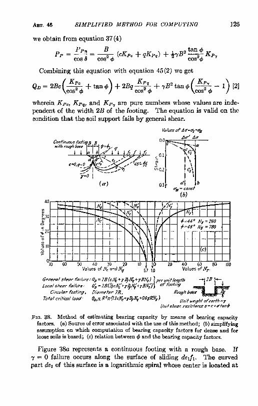
- cp respectively, the values K py and Ny depend only on cp. Therefore Ny can be computed once for all. The relationship between Ny and cp is represented by the solid line marked N.., in Figure 38c.
46. Simplified method for computing bearing capacity. If the supporting soil has cohesion, the computation of the critical load QD per unit of length of a footing by means of equation 45 (2) requires the determination of the component Pp of the passive earth pressure which involves several hours of work. However, in connection with practical problems we are usually satisfied with a less accurate value for the critical load. The method is based on the equation
37(4)
wherein PPn is the normal component of the passive earth pressure on a plane contact face with a height H, a is the slope angle of the contact face, and K pe, K pq, and Kpy are coefficients whose values are independent of Hand 'Y. If ad in Figure 37c represents the contact face the values H, a, and ~ contained in the preceding equation are equal to
H = B tan cp, a = 1800 - cp, ~ = cp, and Ca = c
Considering in addition that the total passive earth pressure Pp on the contact face is equal to PPn/cos ~, or
[1]
ART. 46 SIMPLIFIED METHOD FOR COMPUTING 125
we obtain from equation 37 (4)
PPn B 1 2 tan cp Pp = -- = --2- (cKPe + qKpq) + 2YB -2- Kp"f
cos «5 cos cp cos cp
Combining this equation with equation 45(2) we get
QD = 2Bc (K;c + tan cp) + 2Bq K;q + 'YB2 tan cp (K;"f - 1\) [2] cos cp cos cp cos cp
wherein K pe• Kpq, and Kp"f are pure numbers whose values are independent of the width 2B of the footing. The equation is valid on the condition that the soil support fails by general shear.
Ii) Cl>
40
~3 0 w
o c ';2 0 ..... o
'" ~1O ~
o 70
-
60
( «)
f{" .... .... --- r---" f{,,' c
Hc r---. ........ f'
" ....
50 40 30 20 Values of Nr. andNq
c O.1 o L
\1)0.2
0.3
f{,,' 'I /2v: , , ./
\ ; V \1\. il
\ \ 'I
" \ 11\ 1,\\ ~ , I
10 ~O 2()
5.7 1.0
j.d I-"""N,-
,p:44° NT = 260 ,--p=48° NT = 780
c)
40 60 80 100 Values of Nr ·
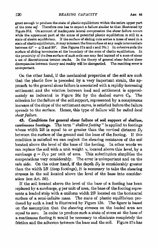
FIG. 38. Method of estimating bearing capacity by means of bearing capacity factors. (a) Source of error associated with the use of this method; (b) simplifying assumption on which computation of bearing capacity factors for dense and for loose soils is based; (c) relation between cp and the bearing capacity factors.
Figure 38a represents a continuous footing with a rough base. If 'Y = 0 failure occurs along the surface of sliding del/t. The curved part del of this surface is a logarithmic spiral whose center is located at
126 BEARING CAPACITY
point b (Prandtl 1920). The equation of the spiral is
r = TO ltan '"
ABT.46
[3]
wherein 8 is the center angle in radians measured from the zero vector ro = bd as shown in Figure 38a. For '" = 0 equation 3 represents the equation of a circle with a radius TO. Since the equation representing the surface of sliding contains neither c nor q, the shape of the surface of sliding is independent of the cohesion and the surcharge. For 'Y = 0 we obtain for the load required to produce a general shear failure along the surface of sliding dedi the value
( Kpc ) Kpq
Qo + Qq = 2Bc -2- + tan cp + 2Bq -2-cos '" cos '"
= 2BcNc + 2BqNq [4]
The factors N c and N q are pure numbers whose values depend only on the value cp in Coulomb's equation. The value Qc represents the load which the weightless soil could carry if the surcharge q were equal to zero ("( = 0 and q = 0), and Qq is the load which it could carry if its bearing capacity were exclusively due to the surcharge q ('Y = 0 and c = 0).
On the other hand, if c = 0 and q = 0, while 'Y is greater than zero, the failure occurs along deJ2 (Fig. 38a). The rigorous equation of the curved part of this line is not yet known. Its approximate shape can be determined either by means of the spiral or the friction circle method (Arts. 39 and 40). The results of such investigations show that the lowest point of the curve de2 is located well above the lowest point of del. The crit:'calload required to produce a failure along deJ2 is determined by the equation
Q'Y = 'YB2 tan cp (K~'Y - 1) = 2B X 'YBN'Y cos cp
45 (4a)
If the values c, D" and 'Yare greater than zero, the failure occurs along a surafce of sliding de! (Fig. 38a), which is located between bedl and beJ2. From the results of numerical computations we know that the corresponding critical load, QD per unit of length of the strip, is only slightly greater than the sum of the loads Qc + Qq (eq. 4) and Q." (eq.45(4a». Therefore we can assume with sufficient accuracy
QD = Qc + Qq + Q'Y = 2BcNc + 2BqNq + 2B2'YN.,
wherein 2B is the width of the footing. SUbstituting q = 'YD, we get
QD = Qc + QIl + Q'Y = 2B(cN" + 'YDINq + 'YBN.,) [5]
ART. 46 SIMPLIFIED METHOD FOR CO/vlPUTING 127
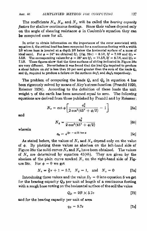
The coefficients N c, N q, and N"f will be called the bearing capacity factors for shallow continuous footings. Since their values depend only on the angle of shearing resistance ¢ in Coulomb's equation they can be computed once for all.
In order to obtain information on the importance of the error associated with equation 5, the critical load has been computed for a continuous footing with a width 2B whose base is located at a depth 2B below the horizontal surface of a mass of ideal sand. For", = 34° we obtained bit (Fig. 38a) = 8.5B, bf = 7.0B and b!2 = 5.5B. The corresponding values for", = 38° are bit = ll.5B, bf = 8.7B, and b!2 = 7.1B. These figures show that the three surfaces of sliding indicated in Figure 38a are very different. Nevertheless it was found that the load QD required to produce a shear failure on def is less than 10 per cent greater than the sum of the loads Qq and Q"f required to produce a failure on the surfaces deJ/l and de2!2 respectively.
The problem of computing the loads Qc and Qq in equation 4 has been rigorously solved by means of Airy's stress function (PrandtI1920, Reissner 1924). According to the definition of these loads the unit weight'Y of the earth has been assumed equal to zero. The following equations are derived from those published by Prandtl and by Reissner:
and
wherein
N = cot 6 - 1 [ a2 ]
c cp 2 cos2 (45° + cp/2)
a - (to" - ",/2) tan '" 6 - E
[6a]
[6b]
[6c]
As stated before, the values of Nc and N q depend only on the value of cpo By plotting these values as abscissa on the left-hand side of Figure 38a the solid curves Nc and N q have been obtained. The values of N"f are determined by equation 45(4b). They are given by the abscissa of the plain curve marked N l' on the right-hand side of Figure 38c. For cp = 0 we get
Nc = !7r + 1 = 5.7, N q = 1, and N"f = 0 [7al
Introducing these values and the value D I = 0 into equation 5 we get for the bearing capacity QD per unit of length of a continuous footing with a rough base resting on the horizontal surface of the soil the value
QD = 2B X 5.7c
and for the bearing capacity per unit of area
qD = 5.7c
[7b]
[7cl
128 BEARING CAPACITY ART. 46
For q, = 34° we get
Nc = 41.9, N q = 29.3, and Nor = 36.0
The bearing capacity QD per unit of length of a continuous footing resting on the surface of the soil (depth of foundation D, = 0) is
QD = 2B X 41.9c + 2B2 X 36.0."
and the average load per unit of area at the instant of failure is equal to
qD = 41.9c + 36.0B-y
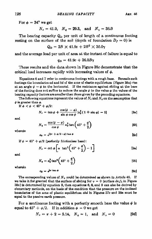
These results and the data shown in Figure 38c demonstrate that the critical load increases rapidly with increasing values of q,.
Equations 6 and 7 refer to continuous footings with a rough base. Beneath such footings the boundaries ad and bd of the zone of elastic equilibrium (Figure 38a) rise at an angle", = </I to the horizontal. If the resistance against sliding at the base of the footing does not suffice to reduce the angle", to the value </I the values of the bearing capacity factors are smaller than those given by the preceding equations;
The following equations represent the values of N. and N g on the assumption that 0/1 is greater than 4>.
If 4> < '" < 45° + 4>/2: cas(o/I - 4» 2
N. = tan", + . [as ( 1 + sin 4» - 1] [Sal Sill of> cos '"
and
[Sbl
wherein [ScI
If '" = 45° + 4>/2 (perfectly frictionless base):
N. = cot 4> [a tan2( 45° +~) - 1] (9al
and
[9bl
wherein (gel
The corresponding values of Nor could be determined as shown in Article 45. If we take it for granted that the surface of sliding for 'Y = 0 (surface deJ/I in Figure 3Sa) is determined by equation 3, then equations 6, 8, and 9 can also be derived by elementary methods, on the basis of the condition that the pressure on the inclined boundaries of the zone of plastic equilibrium abd in Figures 37e and 3& must be equal to the passive earth pressure.
For a oontinuous footing with a perfectly smooth base the value", is equal to 45° + q,/2. If in addition q, = 0 we get
Ne = 'II" +2 = 5.14, N q = 1, and Ny = 0 [9d)
ART. 47 CONDITIONS FOR WCAL SHEAR FAILURE 129
Introducing the value No = 5.14 into equation 5 and assuming that the footing rests on the surface of the ground (D, = 0), we obtain for the ultimate bearing capacity QD per unit of length of the footing
QD = 2B X 5.14c [gel
and for the bearing capacity per unit of area
qD = 5.14c [9!l
The corresponding value for a continuous footing with a rough base is qD = 5.7c (equation 7c). Both values are independent of the width of the footing.
If the point of application of the load on a footing is not located exactly at the center line (eccentric loading), the failure of the earth support will start on the side of the eccentricity. As a consequence the sinking of the footing will be associated with a tilting of its base toward the side of eccentricity. If the eccentricity is very small the load required to produce this type of failure is almost equal to the load required for producing a symmetrical general shear failure. The failure occurs on account of intense radial shear on one side of the plane of symmetry in Figure 37, while the deformations in the zone of radial shear on the other side are still insignificant. For this reason the failure is always asso~ ciated with a heave on that side toward which the footing tilts.
47. Conditions for local shear failure of soil support of shallow continuous footings. The stress conditions for the failure of a cohesive soil are approximately determined by the equation
(II = 2c tan ( 45° + ~) + (lIll tan2 (45° + ~) 7 (3)
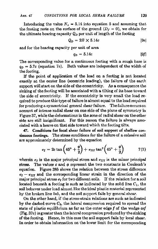
wherein (II is the major principal stress and (lIII is the minor principal stress. The values c and q, represent the two constants in Coulomb's equation. Figure 38b shows the relation between the stress difference (II - tTIll and the corresponding linear strain in the direction of the major principal stress tTl for two different soils. If the relation for a soil located beneath a footing is such as indicated by the solid line ClJ the soil behaves under load almost like the ideal plastic material represented by the broken line Oab, and the soil support fails by general shear.
On the other hand, if the stress-strain relations are such as indicated by the dashed curve C2 , the lateral compression required to spread the state of plastic equilibrium as far as the outer edge I of the wedge aef (Fig. 37 c) is greater than the lateral compression produced by the sinking of the footing. Hence, in this case the soil support fails by local shear. In order to obtain information on the lower limit for the corresponding
130 BEARING CAPACITY ART. 47
critical load QDl we replace the curve C2 by a broken line Oed. It represents the stress-strain relation for an ideal plastic material whose shear values c' and cf/ are smaller than the shear values 0 and cp for the material represented by the curve C2• Replacing the values 0 and cp in equation 7(3) bye' and cf/ we obtain
0'[ = 2c'tan (45 0 + cp' /2) + O'III tan2 (450 + cp' /2) [1]
Since the curve C2 in Figure 38b is located almost entirely on the righthand side of its ideal substitute Oed, the critical load Q~ required to produce a general shear failure in the material represented by equation 1 is somewhat smaller than the load required to produce a local shear failure in the soil represented by the curve C2 • The available data on stress-strain relations suggest that we are justified in assigning to c' and q,' the lower limiting values
0' = ic [2a] and
tan 4/ = t tan q, [2b]
H the soil support fails by general shear, the bearing capacity is determined approximately by equation 46(5). For footings with a rough base the values of the bearing capacity factors N c, N q, and N'Y contained in this equation are given by equations 46(6a to 6c) and 45(4b). In order to compute the corresponding values N:, N~, and N~ for local shear failure we must replace the values cp and 0 in these equations by c' and cp' and the value Pp in equation 45(4b) must be computed on the assumption that the angle of shearing resistance of the supporting soil is equal to cp'. The critical load Q~ is equal to the sum
Q~ = 2B(-!cN~ + 'YDIN~ + 'YBN~) [3]
This equation is the equivalent of equation 46(5). In Figure 38e the values N:, N~, and N~ are represented by the abscissas of the dashed curves N:, N~, and N~ respectively.
The bearing capacity per unit of area of the strip is
, = Q~ = ~ eN' + 'YDIN' + 'YBN' qD 2B 3 c q .., [4]
H the stress-strain relations for a soil are intermediate betN'een the two extremes represented by the curves 0 1 and C2 in Figure 38b, the critical load is intermediate ,between QD and Q~.
48. Distribution of the contact pressure over the base of continuous footings. The term contact pressure indicates the pressure which acts at the surface of contact between the base of a footing and the sup-
ART. 48 DISTRIBUTION OF THE CONTACT PRESSURE 131
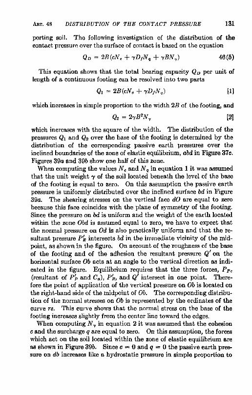
porting soil. The following investigation of the distribution of the contact pressurfl over the surface of contact is based on the equation
46(5)
This equation shows that the total bearing capacity QD per unit of length of a continuous footing can be resolved into two parts
[1]
which increases in simple proportion to the width 2B of the footing, and
Q2 = 2'YB2N'Y [2]
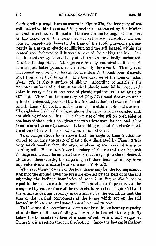
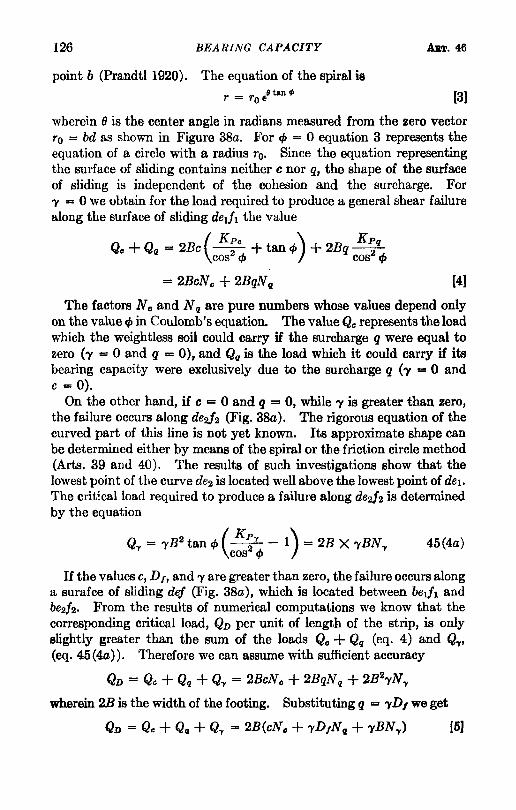
which increases with the square of the width. The distribution of the pressures Ql and Q2 over the base of the footing is determined by the distribution of the corresponding passive earth pressures over the inclined boundaries of the zone of elastic equilibrium, abd in Figure 37c. Figures 39a and 39b show one half of this zone.
When computing the values N c and N q in equation 1 it was assumed that the unit weight 'Y of the soil located beneath the level of the base of the footing is equal to zero. On this assumption the passive earth pressure is uniformly distributed over the inclined surface bd in Figure 39a. The shearing stresses on the vertical face dO are equal to zero because this face coincides with the plane of symmetry of the footing. Since the pressure on bd is uniform and the weight of the earth located within the zone Obd is assumed equal to zero, we have to expect that the normal pressure on Od is also practically uniform and that the resultant pressure P~ intersects bd in the immediate vicinity of the midpoint, as shown in the figure. On account of the roughness of the base of the footing and of the adhesion the resultant pressure Q' on the horizontal surface Ob acts at an angle to the vertical direction as indicated in the figure. Equilibrium requires that the three forces, PPc
(resultant of Pj, and Ca ), P~, and Q' intersect in one point. Therefore the point of application of the vertical pressure on Ob is located on the right-hand side of the midpoint of Ob. The corresponding distribution of the normal stresses on Ob is represented by the ordinates of the curve rs. This curve shows that the normal stress on the base of the footing increases slightly from the center line toward the edges.
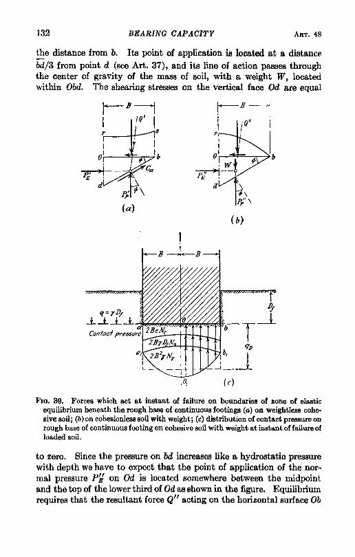
When computing N'Y in equation 2 it was assumed that the cohesion c and the surcharge q are equal to zero. On this assumption, the forces which act on the soil located within the zone of elastic equilibrium are as shown in Figure 39b. Since c = 0 and q = 0 the passive earth pressure on db increases like a hydrostatic pressure in simple proportion to
132 BEARING CAPACITY ART. 48
the distance from b. Its point of application is located at a distance bd/3 from point d (see Art. 37), and its line of action passes through the center of gravity of the mass of soil, with a weight W, located within Obd. The shearing stresses on the vertical face Od are equal
Po' E
r- B ---"1 I If/' I
I:,: "\
(a)
q= TJ)/
s
\ p/\
(b)
.J:... -.l-*--.l~~~~~~~'b:--Contacf pre55t1rf?
( c)
FIG. 39. Forces which act at instant of failure on boundaries of zone of elastic equilibrium beneath the rough base of continuous footings (a) on weightless cohesive soil; (b) on cohesionleBSsoil with weight; (c) distribution of contact pressure on rough base of continuous footing on cohesive soil with weight at instant of failure of loaded Boil.
to zero. Since the pressure on bd increases like a hydrostatic pressure with depth we have to expect that the point of application of the normal pressure Pi! on Od is located somewhere between the midpoint and the top of the lower third of Od as shown in the figure. Equilibrium requires that the resultant force Q" acting on the horizontal surface Ob
ART. 49 SHALLOW SQUARE OR CIRCULAR FOOTINGS 133
passes through the point of intersection of P~ and PjJ. Since Q" slopes toward the center line, its point of application is located at a distance slightly greater than Bf3 from point O. At the outer edge b of the base of the footing the normal pressure on the base of the footing is equal to zero and it increases toward the center point 0 (see Art. 16). These conditions combined require that the distribution of the contact pressure over the base of the footing should be roughly parabolic.
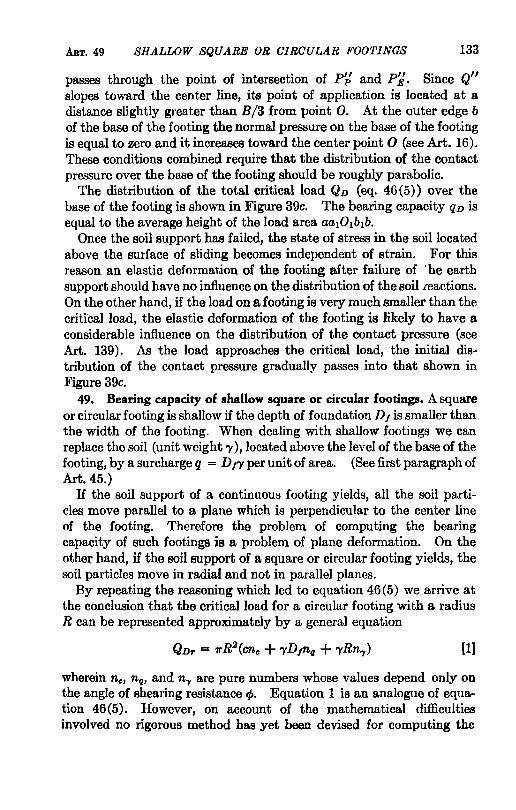
The distribution of the total critical load QD (eq. 46(5» over the base of the footing is shown in Figure age. The bearing capacity qD is equal to the average height of the load area aa10lb1b.
Once the soil support has failed, the state of stress in the soil located above the surface of sliding becomes independent of strain. For this reason an elastic deformation of the footing after failure of 'he earth support should have no influence on the distribution of the soil.leactions. On the other hand, if the load on a footing is very much smaller than the critical load, the elastic deformation of the footing is likely to have a considerable influence on the distribution of the contact pressure (see Art. 139). As the load approaches the critical load, the initial distribution of the contact pressure gradually passes into that shown in Figure 3ge.
49. Bearing capacity of shallow square or circular footings. A square or circular footing is shallow if the depth of foundation D, is smaller than the width of the footing. When dealing with shallow footings we can replace the soil (unit weight 1'), located above the level of the base of the footing, by a surcharge q = D!'Y per unit of area. (See first paragraph of Art. 45.)
H the soil support of a continuous footing yields, all the soil particles move parallel to a plane which is perpendicular to the center line of the footing. Therefore the problem of, computing the bearing capacity of such footings is a problem of plane deformation. On the other hand, if the soil support of a square or circular footing yields, the soil particles move in radial and not in parallel planes.
By repeating the reasoning which led to equation 46(5) we arrive at the conclusion that the critical load for a circular footing with a radius R can be represented approximately by a general equation
[1}
wherein nc, na, and ny are pure numbers whose values depend only on the angle of shearing resistance cpo Equation 1 is an analogue of equation 46(5). However, on account of the mathematical difficulties involved no rigorous method has yet been devised for computing the

134 BEARING CAPACITY ART. 49
coefficients. Until the results of successful theoretical or of adequate experimental investigations are available, we are obliged to estimate the bearing capaci~y on the basis of the limited experience we have at present. The available data will be given in a volume on applied soil mechanics (Golder 1942, Skempton 1942, and unpublished test results). Taking the most unfavorable test results as a basis for establishing a provisional equation, the author obtained from the experimental data for the bearing capacity of a circular area with a radius R
QD = 7rR2qD = 7rR2(1.3cN. + -yD,Nq + 0.6-yRN..,) [2]
wherein N., Nil, and N.y represent the bearing capacity factors for continuous footings, supported by the same soil. For footings covering a square area of 2B X 2B he obtained
QD = 4B2qD = 4B2(1.3cN. + -yD,Nq + 0.8-yBN"I) [3]
If the soil is loose or very compressible, the bearing capacity factors N must be replaced by the values N'. (See Figure 38c.)
Small-scale model tests have shown that the greatest heave of the ground surface surrounding a loaded circular area with a radius R occurs within a distance of about 3R from the center of the loaded area. Beyond a distance of about 5R from the center the heave is imperceptible.
Equation 2 leads to the following conclusions. If the soil support of a continuous footing with a width 2B on a cohesive soil (cjJ = 0) fails under a unit load qD by general shear, the bearing capacity of a circular footing with a diameter 2R is approximately equal to 1.3 qD. On the other hand, if c = 0, D, = 0, and cjJ > 0 the circular footing fails at an average unit load of about 0.6 qD wherein qD is the unit load required to produce a general shear failure beneath a continuous footing with a width 2R, supported by the same material. Experiments on sand and clay have shown the approximate validity of this conclusion. An exact agreement between the computed and the measured values cannot be expected.
50. Bearing capacity of cylindrical piers. In the preceding articles the shearing resistance of the soil located above the level of the base of the footings has been disregarded, because the resulting error is small and on the safe side. However, when dealing with piers whose diameter 2R is small compared to the depth of foundation, no such simplification is justified because the resulting error is likely to be excessive. The effect of the shearing stresses in the soil on the bearing capacity of a pier is illustrated by the right-hand side of Figure 36b. The earth located beneath the annular space represented by bd is acted upon by