dem user guide
DESCRIPTION
Uponor Radio Controls User GuidesTRANSCRIPT

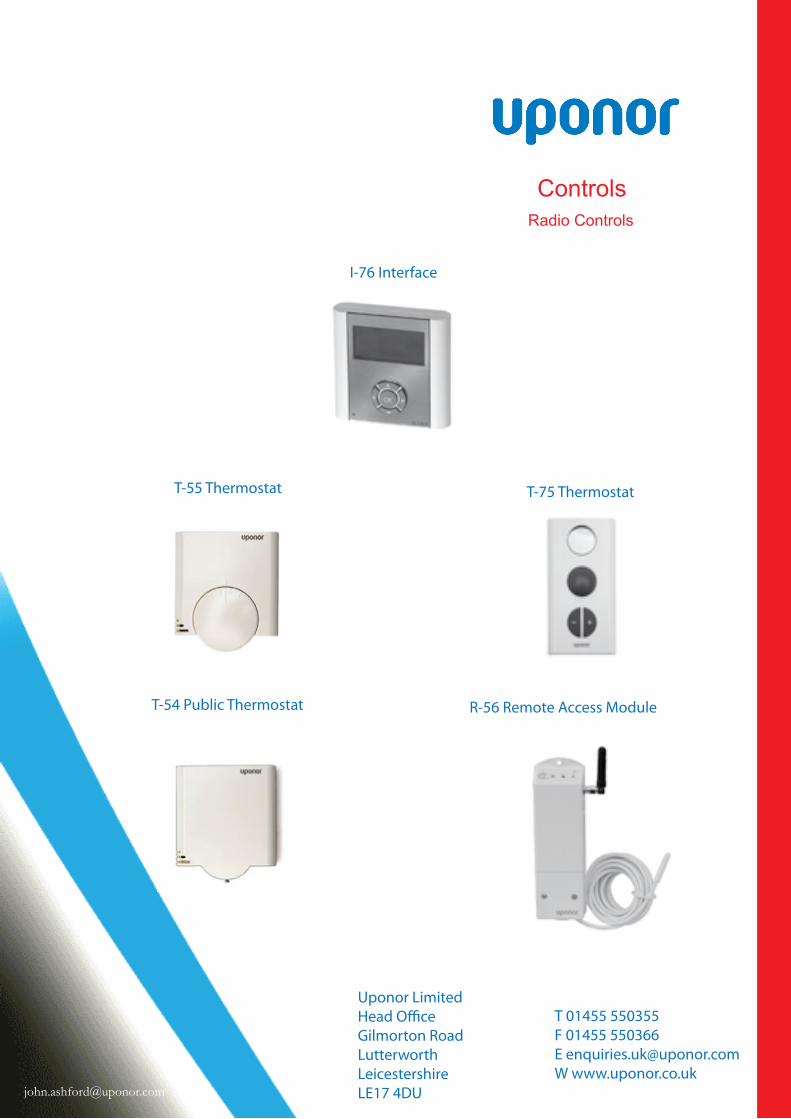
ControlsRadio Controls
Uponor LimitedHead O�ceGilmorton RoadLutterworthLeicestershireLE17 4DU
T 01455 550355F 01455 550366E [email protected] www.uponor.co.uk
Radio Control for Individual Rooms
Uponor High - Level Dynamic Energy Managment
ControlsRadio Controls
Uponor LimitedHead O�ceGilmorton RoadLutterworthLeicestershireLE17 4DU
T 01455 550355F 01455 550366E [email protected] www.uponor.co.uk
T-54 Public Thermostat
T-55 Thermostat
R-56 Remote Access Module
T-75 Thermostat
I-76 Interface

ControlsRadio
Uponor LimitedHead O�ceGilmorton RoadLutterworthLeicestershireLE17 4DU
T 01455 550355F 01455 550366E [email protected] www.uponor.co.uk
I-76 Radio InterfaceUser Guide
T-36Room Thermostat

I-75/76 Interface
Operate Uponor Interface I-75/76
Adding Uponor Interface I-75/76 to the Uponor Control Systemprovides:• Centralized management of the underfl oor system• Rapid display and update of system settingsThe illustration below shows the exterior and interior of UponorInterface I-75/76.
The table below describes the numbered itemsin the illustration.
Item Description
1 Screen 2 Navigation keys 3 Fault indicator 4 Reset button 5 Data stick connection
Use Navigation Keys
Each of the five navigation keys on Uponor Interface I-75/76has dual functions, as described in the table below.
Displays next menu or Moves to next field
Displays previous or Moves to previous fieldmenu. Pressing andholding in a menuscreen displays mainUponor screen
Moves to line above or Increases value
Moves to line below or Decreases value
Displays next screen or Confirms selections; displays screen of current menu
• Press any navigation key to activate backlighting.• Press OK to go to the main menu.
Interface I-75/76 main screen
The table below describes icons displayedon the Uponor mainscreen:
Holiday Mode
Alarm/error message
Temperature set point
Temperature measured
Floor temperature (when fl oor sensor is installed)
Batteries suffi ciently charged
Batteries discharged, replace batteries
Basic access level (Interface I-76 only)
Advanced access level (Interface I-76 only)
Icon Description
The outdoor temperature is displayed if the system hasThermostat T-54 Public with an outdoor sensor installed.
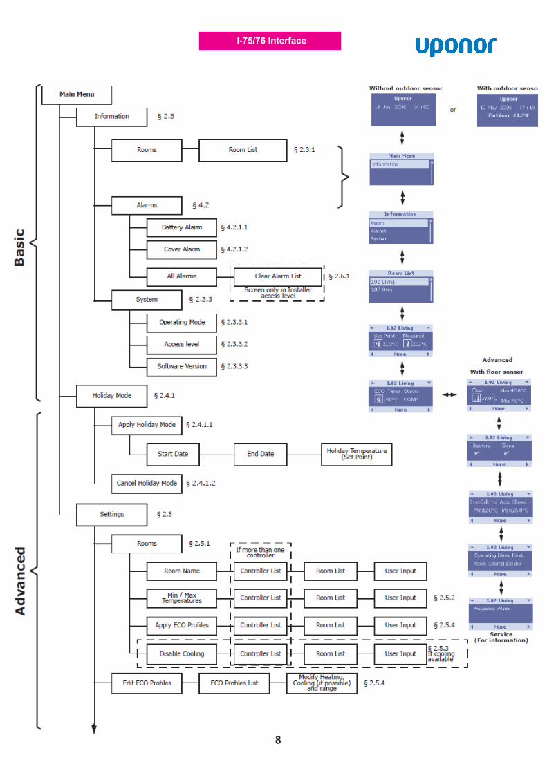
Interface I-75/76 main menu
The table below describes the numbered itemsin the example.
1 Upper banner displays menu heading
2 Information zone: the selected line is highlighted
3 Scroll bar
Item Description
1

I-75/76 Interface
Access and Navigate Menu
To access room information from the menu:
1 Press the OK navigation key to display the Main Menu.
2 Select Information and press OK.The information menu is displayed.
3 Select Rooms and press OK. The list of rooms is displayed.
4 Select the desired room and pressOK. Information for the selectedroom is displayed.
5 Display the desired informationusing the navigation keys.Use and to display theprevious/next screen.Use and to display theprevious/next thermostat.
Press OK to return to the room list.
Select access levelTwo access levels are available for operation:
• Basic allows the users to view basic information but not tomodify settings. Basic mode can be used in a public locationor rented accommodation, for example.
• Advanced allows users both to view and modify settings.
To select the access level:
1 On the Uponor screen, select Main Menu > Settings >System Parameters > Access Level.
2 Select Basic or Advanced andpress OK.
To switch from Basic to Advanced level,on the Uponor screen,simultaneously press and until the Advanced screen appears.
Select Advanced and press OK to put the system in advanced level.
Display room information
The digits at the beginning of the room name on the displaymean:
• 1st digit – controller number (1, 2, 3).
• 2nd and 3rd digits – number of the fi rst channel controlled by this thermostat (01, 02, 03, and so on). If several channels are controlled by the thermostat, only the lowest channel number is displayed.
To display room information:
1 On the Uponor screen, select Main Menu > Information >Rooms.
2 Select the desired room and press OK.
Meanings of the temperature icons as shown in the examplescreens below.
Icon Description of Use Screen Example
If temperature set on thermostatis outside allowed temperaturerange for room, limitationtemperature is displayed as setpoint.
Measured temperature is 21.2 °C.
Temperature setting for roomwhen in ECO mode. (Currentsetting 19 °C).Options for current status:COMF: Comfort mode.ECO: Economy mode.
This screen is displayed if there isa fl oor sensor in the room. Floortemperature is 23 °C.Max and Min - Minimum andmaximum fl oor temperature setpoint is displayed.
Display Battery and Communication StatusTo display battery and communication status:
Icon Description of Use Screen ExampleBattery: batteries are suffi cientlycharged.Signal: radio signal from thethermostat and antenna is good.
Battery: batteries aredischarged.Signal: radio signal from antennaor thermostat is poor or faulty.2

I-75/76 Interface
Display Room Thermostat Status
Icon Description of Use Screen Example
display thermostat and actuator status of a room:
Stat call Yes: thermostat is calling for heating (or cooling). No: thermostat is reporting that room temperature is OK.
Act. Open: actuators are powered and open or on delay and will open soon. Closed: no power to the actuators, which are closed (or closing).
Min. Minimum set point of room is set at 20 °C.
Max. Maximum temperature set point of room is set at 26 °C.
Select Heating or Cooling ModeTo select heating or cooling mode:
System Status Heating or cooling mode is activated for the whole system.
Room Cooling Enable: Cooling the room is allowed. Disable: Cooling the room is not allowed.
Use Holiday Mode
Use holiday mode to set a common temperature reduction for allrooms for a specified time. The thermostat settings are ignoredduring this period.
The reduced holiday set point applies to all installed roomthermostats. The setting range is 5 to 35 °C.
The minimum and maximum thermostat limitations have priorityover the holiday mode. For example, if the maximum/minimumtemperature range of a room thermostat is set to 20 °C to 25 °C,and holiday mode temperature is set to 15 °C for all rooms, thetemperature for this room will not go below 20 °C.
Floor sensor thermostat settings have priority over holidaymode maximum and minimum limitations.
To apply holiday mode:1 On the Uponor screen, select Main Menu > Holiday Mode > Apply Holiday Mode.
2 Enter the time and date for the start of the holiday period and press OK.
3 Enter the time and date for the end of the holiday period and press OK.
4 Enter the holiday temperature set point and press OK.
The icon on the main screenindicates that the system is in holidaymode.
To cancel holiday mode:
1 On the Uponor screen, select Main Menu > Holiday Mode > Cancel Holiday Mode.
2 Select Yes and press OK.
Assign Room Name
The digits at the beginning of the room name on the displaymean:
• 1st digit – controller number (1, 2, 3).• 2nd and 3rd digits – number of the fi rst channel controlled by the thermostat (01, 02, 03, and so on). If several channels are controlled by the thermostat, only the lowest channel number is displayed.
To assign a room name:
1 On the Uponor screen, select Main Menu > Settings > Rooms > Room names.
2 Select the desired controller (applies only when more than one is installed) and press OK.
3 Select the desired room or thermostat and press OK.
4 Select the room name from the list and press OK.
3

I-75/76 Interface
Set minimum/maximum temperaturesExample: If the temperature set point of the thermostat is setto 5 °C, the temperature will not fall below 12 °C because theminimum and maximum limitations for this room are set to 12and 26 °C respectively.
To set minimum and maximum temperatures:
1 On the Uponor screen, select Main Menu > Settings > Rooms > Min/Max Temperatures.2 Select the desired controller or All for all rooms on all controllers and press OK.
Selecting All sets the same minimum and maximum temperatures for all rooms.
3 Select a thermostat or room and press OK.
4 Set the temperatures. Use and to increase and decrease the value. Use and to toggle between minimum and maximum.
Press OK.
Disable Cooling
Use this setting to exclude specifi c rooms from cooling mode,for example, a bathroom or garage. This menu is displayed onlywhen cooling is activated during installation.
To disable cooling:
1 On the Uponor screen, select Main Menu > Settings > Rooms > Disable Cooling.
2 Select the controller (applies only when more than one is installed) and press OK.
3 Select a thermostat or room and press OK.
4 Select Yes to disable cooling for the room (or all rooms) and press OK.
To set the temperature unit:
1 On the Uponor screen, select Main Menu > Settings > System Parameters > Temperature Unit.
2 Select °C or °F and press OK.
Set temperature unit
Set Time and Date
To set the time and date:
1 On the Uponor screen, select Main Menu > Settings > System Parameters > Clock Settings > Set Date/Time.
Toggle between the fields using the and keys. Change the values using the and keys.
2 Change the time and date and press OK.
Set time format
To set time format:
1 On the Uponor screen, select Main Menu > Settings > System Parameters > Clock Settings > Time Format.
2 Select 24 hour or AM/PM and press OK.
Set date format
To set date format:
1 On the Uponor screen, select Main Menu > Settings > System Parameters > Clock Settings > Date Format.
2 Select the format and press OK.
4
I-75/76 Interface
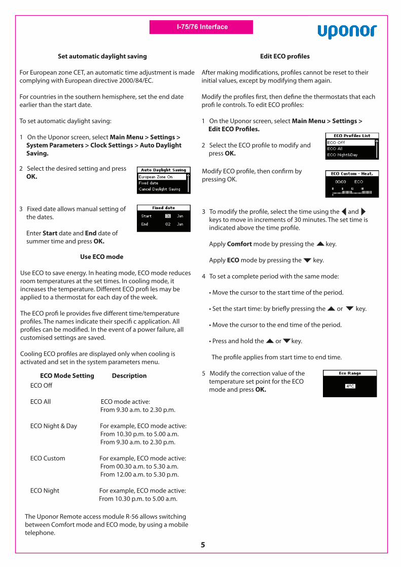
Set automatic daylight saving
For European zone CET, an automatic time adjustment is madecomplying with European directive 2000/84/EC.
For countries in the southern hemisphere, set the end dateearlier than the start date.
To set automatic daylight saving:
1 On the Uponor screen, select Main Menu > Settings > System Parameters > Clock Settings > Auto Daylight Saving.
2 Select the desired setting and press OK.
3 Fixed date allows manual setting of the dates.
Enter Start date and End date of summer time and press OK.
Use ECO mode
Use ECO to save energy. In heating mode, ECO mode reducesroom temperatures at the set times. In cooling mode, itincreases the temperature. Di�erent ECO pro� les may beapplied to a thermostat for each day of the week.
The ECO pro� le provides �ve di�erent time/temperaturepro�les. The names indicate their speci� c application. Allpro�les can be modi�ed. In the event of a power failure, allcustomised settings are saved.
Cooling ECO pro�les are displayed only when cooling isactivated and set in the system parameters menu.
ECO Mode Setting DescriptionECO O�
ECO All ECO mode active: From 9.30 a.m. to 2.30 p.m.
ECO Night & Day For example, ECO mode active: From 10.30 p.m. to 5.00 a.m. From 9.30 a.m. to 2.30 p.m.
ECO Custom For example, ECO mode active: From 00.30 a.m. to 5.30 a.m. From 12.00 a.m. to 5.30 p.m.
ECO Night For example, ECO mode active: From 10.30 p.m. to 5.00 a.m.
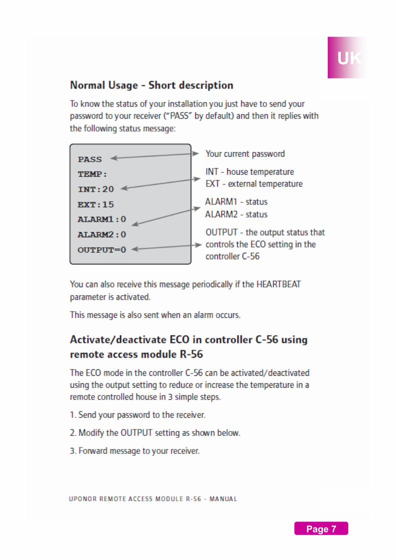
The Uponor Remote access module R-56 allows switchingbetween Comfort mode and ECO mode, by using a mobiletelephone.
Edit ECO pro�les
After making modi�cations, pro�les cannot be reset to theirinitial values, except by modifying them again.
Modify the pro�les �rst, then de�ne the thermostats that eachpro� le controls. To edit ECO pro�les:
1 On the Uponor screen, select Main Menu > Settings > Edit ECO Pro�les.
2 Select the ECO pro�le to modify and press OK.
Modify ECO pro�le, then con�rm bypressing OK.
3 To modify the pro�le, select the time using the and keys to move in increments of 30 minutes. The set time is indicated above the time pro�le.
Apply Comfort mode by pressing the key.
Apply ECO mode by pressing the key.
4 To set a complete period with the same mode:
• Move the cursor to the start time of the period.
• Set the start time: by briefly pressing the or key.
• Move the cursor to the end time of the period.
• Press and hold the or key.
The pro�le applies from start time to end time.
5 Modify the correction value of the temperature set point for the ECO mode and press OK.
5

I-75/76 Interface
Apply ECO pro�les
To check the ECO pro�le settings, select the days to check byusing and for each day. The assigned timer programme isdisplayed.
To apply ECO pro�les:
1 On the Uponor screen, select Main Menu > Settings > Rooms > Apply ECO pro�le.
2 Select the desired controller or all controllers (applies only when more than one is installed) and press OK.
3 Select the desired room or All and press OK.
If one ECO pro�le is used in most rooms, apply the pro�le to every room by selecting the setting All.
4 Select the day by using the and keys and brie�y pressing the key on the desired day. The current pro�le is displayed.
5 Select ECO Pro�les mode by pressing the key.
6 Select the desired ECO pro�le and press OK. Repeat the settings for each day.
Exercise functionality of valves and pumps
The exercise function maintains the functionality of the valvesand pumps. A 5-minute activation is scheduled each week.
Cancel exercise
To cancel the exercise:
1 On the Uponor screen, select Main Menu > Settings > System Parameters > Valve/Pump Exercise > Cancel Exercise.
2 Select Cancel Exercise and press OK.
Exercise valves and pumps
To run the exercise for both valves and pumps:
1 On the Uponor screen, select Main Menu > Settings > System Parameters > Valve/Pump Exercise > Exercise Valve and Pump.
2 Set the time and date for the 5-minute activation and press OK.
Exercise valves only
To run the exercise for valves only:
1 On the Uponor screen, select Main Menu > Settings > System Parameters > Valve/Pump Exercise > Exercise Valve Only.
2 Set the time and date for the 5-minute activation and press OK.
Set display backlight
To set the display backlight:
1 On the Uponor screen, select Main Menu > Settings > System Parameters > Backlight.
2 Select: • Always ON
• Dimmed (when inactive) for reduced screen brightness.
• OFF (when inactive) backlighting is o�.
Press OK.
Display software version
To display the software version of Uponor Interface I-75/76:1 On the Uponor screen, select Main Menu > Information >System > Software Version.
X.X.X Software version.
(X.X.X) Hardware version.
6
I-75/76 Interface
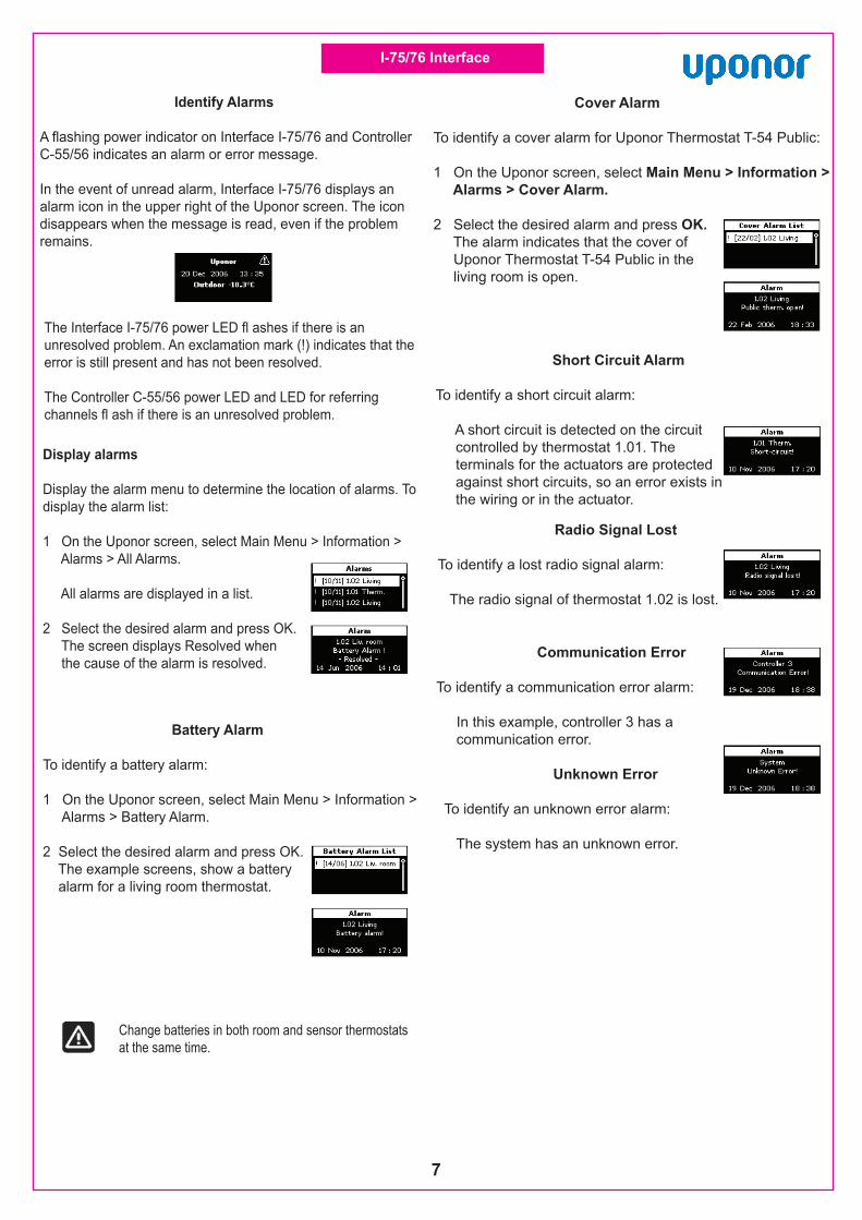
Identify Alarms
A flashing power indicator on Interface I-75/76 and ControllerC-55/56 indicates an alarm or error message.
In the event of unread alarm, Interface I-75/76 displays analarm icon in the upper right of the Uponor screen. The icondisappears when the message is read, even if the problemremains.
The Interface I-75/76 power LED fl ashes if there is anunresolved problem. An exclamation mark (!) indicates that theerror is still present and has not been resolved.
The Controller C-55/56 power LED and LED for referringchannels fl ash if there is an unresolved problem.
Display alarms
Display the alarm menu to determine the location of alarms. Todisplay the alarm list:
1 On the Uponor screen, select Main Menu > Information > Alarms > All Alarms.
All alarms are displayed in a list.
2 Select the desired alarm and press OK. The screen displays Resolved when the cause of the alarm is resolved.
Battery Alarm
To identify a battery alarm:
1 On the Uponor screen, select Main Menu > Information > Alarms > Battery Alarm.
2 Select the desired alarm and press OK. The example screens, show a battery alarm for a living room thermostat.
Change batteries in both room and sensor thermostatsat the same time.
Cover Alarm
To identify a cover alarm for Uponor Thermostat T-54 Public:
1 On the Uponor screen, select Main Menu > Information > Alarms > Cover Alarm.
2 Select the desired alarm and press OK. The alarm indicates that the cover of Uponor Thermostat T-54 Public in the living room is open.
Short Circuit Alarm
To identify a short circuit alarm:
A short circuit is detected on the circuit controlled by thermostat 1.01. The terminals for the actuators are protected against short circuits, so an error exists in the wiring or in the actuator.
Radio Signal Lost
To identify a lost radio signal alarm:
The radio signal of thermostat 1.02 is lost.
Communication Error
To identify a communication error alarm:
In this example, controller 3 has a communication error.
Unknown Error
To identify an unknown error alarm:
The system has an unknown error.
7
I-75/76 Interface
8

I-75/76 Interface
9
ControlsRadio
Uponor LimitedHead O�ceGilmorton RoadLutterworthLeicestershireLE17 4DU
T 01455 550355F 01455 550366E [email protected] www.uponor.co.uk
T-55 Room ThermostatUser Guide
T-36Room Thermostat

T-55 Operating Buttons
[email protected] 2012
Operate Thermostat T-55
During normal operation the thermostat LED flashes once only with each radio transmission.
The illustration below shows the parts of the thermostat.
The table below describes the numbered items in the illustration
Item Description
1 Room temperature set point dial control
Registration Button 2
Batteries
Radio Transmission LED 4
3
Blue cam to set minimum temperature
Red cam to set maximum temperature
5
6

T-55 Operating Buttons
[email protected] 2012
Adjust Temperature
Use the control dial of the thermostat to adjust the temperature. The illustration below shows how to adjust the thermostat set point
To adjust the thermostat temperature
Rotate the dial clockwise for a higher temperature Rotate the dial anti-clockwise for a lower temperature
Set minimum and maximum temperatures
The illustration below shows how to set minimum and maximum temperatures in the thermostat. If the system is equipped Uponor interface I-75/76, all the minimum/maximum settings can be handled from
there, and procedures below are not necessary.
To set minimum and maximum temperatures
1 - Remove the dial with a screwdriver 2 - Set the desired minimum temperature of the room with the blue cam.
3 - Set the maximum temperature with the red cam.

ControlsRadio
Uponor LimitedHead O�ceGilmorton RoadLutterworthLeicestershireLE17 4DU
T 01455 550355F 01455 550366E [email protected] www.uponor.co.uk
T-54 Public ThermostatUser Guide
T-36Room Thermostat

T-54 Public Thermostat
[email protected] 2012
Operate Thermostat T-54
Uponor Thermostat T-54 Public contains a switch that sends an alarm when the thermostat cover is opened. The alarm is transmitted by radio, causing both the power LED and related channelled to flash.
During normal operation the thermostat LED flashes once only with each radio transmission.
The illustration below shows the parts of the thermostat.
The table below describes the numbered items in the illustration
Item Description
1 Screw for opening thermostat
Terminal for external sensor ( not polarized ) 2
Batteries
Setpoint temperature potentiometer 4
3
Configuration switches
Floor sensor potentiometer
5
6
Replace Batteries The thermostats are powered by batteries.
Replace the batteries of the thermostat when the red LED flashes inside. The thermostat
flashes twice during heating or cooling demand.
The illustration shows how to open the thermostat.
8
Registration Button 7
Radio transmission LED

T-54 Public Thermostat
[email protected] 2012
Change Temperature Setpoint
It is not possible to set minimum and maximum temperatures using the Uponor Thermostat T-54 Public unless Uponor Interface I-75/76 is installed.
To change the Uponor Thermostat T-54 Public temperature setpoint:
1 Remove the cover 2 Select the desired temperature using the potentiometer
3 Put back the cover and tighten in place
The illustration below shows how to change the temperature setpoint in the Uponor Thermostat T-54 Public

T-54 Public Thermostat
[email protected] 2012
Adjust Floor Sensor
If the system includes a floor sensor, the potentiometer behind the cover of Uponor Thermostat T-54 Public Allows minimum or maximum temperature settings of the floor sensor
To change Uponor Thermostat T-54 Public floor sensor settings
1 Select the desired temperature using the potentiometer
The floor sensor limits the maximum or minimum floor temperature, regardless of room temperature. The maximum limitation can be used to prevent sensitive floor covering from exposure to excessive
high temperature when there is a high heat demand
Embedded in concrete slab
Embedded in wooden suspended floor

ControlsRadio
Uponor LimitedHead O�ceGilmorton RoadLutterworthLeicestershireLE17 4DU
T 01455 550355F 01455 550366E [email protected] www.uponor.co.uk
T-75 ThermostatUser Guide
T-36Room Thermostat

T-75 Thermostat
[email protected] 2012
Operating Uponor T-75 with Display
Batteries for Thermostats
All thermostats use two alkaline 1,5V AAA batteries. Ensure that the batteries are correctly inserted in the thermostats
Clean Thermostats
Use a dry soft cloth to clean the thermostats
Do not use detergent or any other liquids
The thermostat displays the room temperature during normal operation, as shown in the illustration.
The table below describes the numbered items in the illustration
2
1
3
LCD Display
Temperature Sensor for Ambient Temperature
+ and - Keys to Set Temperatures

T-75 Thermostat
[email protected] 2012
Operating Uponor T-75 with Display The table below describes the icons displayed on the Uponor Thermostat display T-75
Temperature display with menus and precision of 0.1º
Displayed when setting the temperature set point
Displayed during radio transmission
Temperature format for the display
Low battery indicator
Change Temperature Format
To change the temperature format to Celsius or Fahrenheit:
1 Simultaneously press the + and - keys until the SEL menu appears. 2 Press + or - to change the temperature format ( ºC or ºF ) and wait until the thermostat returns to the initial display
Adjust Temperature Use the + or - key of the thermostat to adjust the temperature. To reset the temperature set point to the start up value of 22.0ºC ( 72.0ºF), gently press the + and - key simultaneously. 1 Press the + or - key. The set point icon and value are displayed. 2 Press + or - to change the set point value: For ºC setting by 0.5 ºC steps. For ºF setting by 1 ºF steps. 3 Wait until the radio transmission icon is displayed, confirming that The set point has changed, and the display returns to normal.
Set Minimum/Maximum Temperatures
The minimum and maximum temperatures ( 5ºC and 35ºC ) of the thermostat are set and can not be changed unless the system is
equipped with the Uponor Interface T-75/76
Replace Batteries
The thermostat is powered by batteries. Replace the batteries of the thermostat when the symbol is displayed.
The illustration shows how to open the thermostat

ControlsRadio
Uponor LimitedHead O�ceGilmorton RoadLutterworthLeicestershireLE17 4DU
T 01455 550355F 01455 550366E [email protected] www.uponor.co.uk
R-56 Remote Access ModulUser Guide
T-36Room Thermostat

UK
Page 1

Page 2
UK

Page 3
UK

UK
Page 4
Page 5
UK

Page 6
UK
Page 7
UK

Page 8
UK