delta test report -...
TRANSCRIPT

DELTA Danish Electronics,
Light & Acoustics
Venlighedsvej 4
2970 Hørsholm
Denmark
Tel. (+45) 72 19 40 00
Fax (+45) 72 19 40 01
www.delta.dk
This report is issued under the rules of DANAK (Danish Accreditat ion) and ILAC (Internat ional Laboratory Accreditat ion Cooperat ion) including its MRA (Mutual Recognit ion Arrangement). Further information can be found at www.danak.dk and www.i lac.org. The report must not be reproduced, except in ful l, without the written approval of DELTA.
DELTA Test Report
Version m
TEST Reg. no. 19
W e h e l p i d e a s m e e t t h e r e a l w o r l d
Type approval testing of miscellaneous smoke and heat detectors for marine applications Performed for Consilium Marine AB DANAK-199842 Project no.: A530277 Page 1 of 44 including 3 annexes 15 February 2007

DANAK-199842 DELTA-A530277 Page 2 of 44
EbC/jh
Title Type approval testing of miscellaneous smoke and heat detectors for marine applications
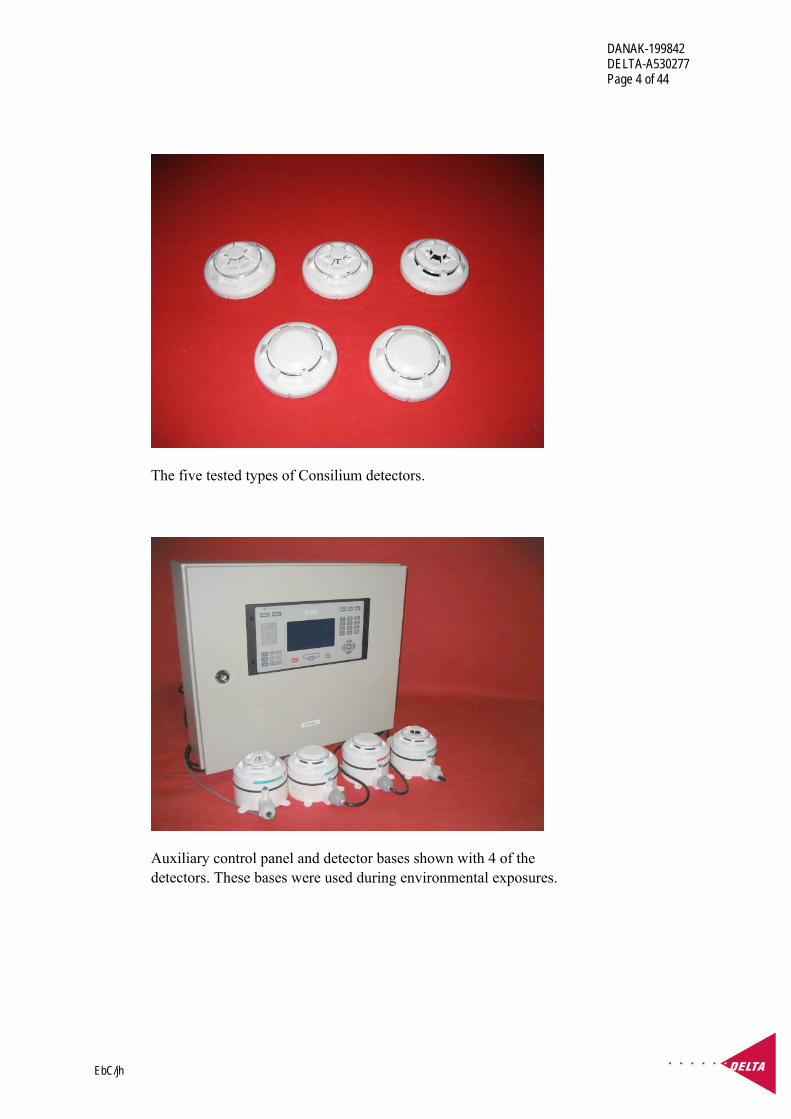
Test objects Five analogue addressable detector types:
Salwico, EV-H-A1R Heat detector, class A1R
Salwico, EV-H-CS Heat detector, class CS
Salwico, EV-P Optical smoke detector
Salwico, EV-DP Double optical smoke detector
Salwico, EV-PH Optical smoke/ heat detector, class A1R
A photo of all the tested objects is given on Page 4.
Photos of each of the test objects are given in Annex 1.
The detectors were received by DELTA for testing on 2 June 2006.
Report no. DANAK-199842
Project no. A530277
Test period June - December 2006
Client Consilium Marine AB Salsmästaregatan 21 Box 8763 402 76 Göteborg Sweden
Telephone: +46 31 710 77 00 Fax: +46 31 710 78 00
Contact person Mr. Björn Lindström E-mail: [email protected]
Manufacturer Nittan (UK) Limited
Specifications IACS E10 "Test Specification for Type Approval", Rev. 4, May 2004, ", issued by the International Association of Classification Societies (IACS)

DANAK-199842 DELTA-A530277 Page 3 of 44
EbC/jh
Results The results are given in a summary in Chapter 4
Technical documentation
The technical documentation is listed in Annex 1.
Test personnel Peter Tjell Jan B. Nielsen Claus M. Thomsen Chris J. Pilbeam Olling Truelsen Poul Terkelsen Bjørn B. Petersen
Date 15 February 2007
Responsible
Ebbe Christensen, B.Sc.E.E. DELTA
DANAK-199842 DELTA-A530277 Page 4 of 44
EbC/jh
The five tested types of Consilium detectors.
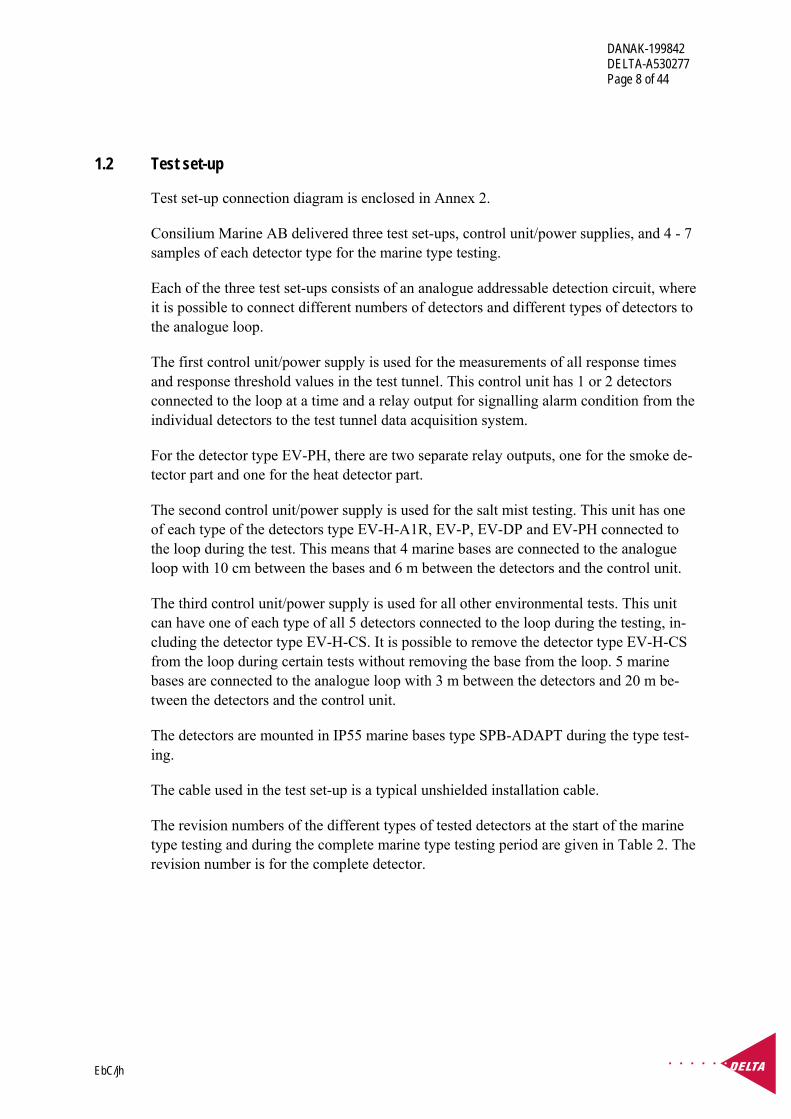
Auxiliary control panel and detector bases shown with 4 of the detectors. These bases were used during environmental exposures.

DANAK-199842 DELTA-A530277 Page 5 of 44
EbC/jh
Table of contents Page
1. General 6 1.1 Introduction 6 1.2 Test set-up 8 1.3 Functional test procedure 9 1.3.1 Simple functional testing 9 1.3.2 Measurements of response time for heat detectors and response threshold value
for smoke detectors 10 1.4 General criteria for passing the tests 11 1.5 Modifications of test objects during testing 11 1.6 References 11
2. Tests in standard environment 12 2.1 Insulation resistance 12 2.2 High voltage 13
3. Environmental tests 16 3.1 Dry heat 16 3.2 Damp heat, cyclic 19 3.3 Vibration 22 3.4 Cold 25 3.5 Salt mist 27 3.6 Radiated emission 29
4. Summary 31
Annex 1 Documentation for the test objects 32
Annex 2 Documentation for the test set-up 36
Annex 3 Test set-up and test record sheets regarding radiated emission 38

DANAK-199842 DELTA-A530277 Page 6 of 44
EbC/jh
1. General
1.1 Introduction
This report describes the marine type approval testing of five types of analogue address-able smoke and heat detectors carried out to achieve compliance with the specification:
• IACS E10 "Test Specification for Type Approval", Rev. 4, May 2004, issued by the International Association of Classification Societies (IACS)
An assessment to verify if the detectors fulfil the relevant requirements of the IACS E10 by evaluation of the validity of the previous tests and the standards used at that time compared with the IACS E10 has previously been carried out and reported. The assess-ment was reported in Ref. /1/ of Section 1.6. The assessment report describes which sup-plementary marine tests should be carried out to achieve compliance with the IACS E10 specification. In addition to these tests, Consilium Marine AB also requested dry heat and damp heat cyclic to be included for the heat detectors class A1R. This resulted in the following test plan, where the notation is defined in Table 1:
Table 1
IACS E10 Test no.
Salw
ico
EV
-H-A
1R
Salw
ico
EV
-H-C
S
Salw
ico
EV
-P
Salw
ico
EV
-DP
Salw
ico
EV
-PH
1. Visual inspection X X X X X 2. Performance test X X X X X 3. External power supply failure NR NR NR NR NR 4. Power supply variation a) electric
NR NR NR NR NR
5. Dry heat, 70°C X X X X X
6. Damp heat cyclic 55°C (+ insulation resistance)
X X X X X
7. Vibration, 4 g X ⇐ X X X 8. Inclination NR NR NR NR NR 9. Insulation resistance X ⇐ X X X 10. High voltage (+ insulation resistance)
X ⇐ X X X
11. Cold, -25°C (+ insulation resistance)
X ⇐ X X X
12. Salt mist (+ insulation resistance)
X ⇐ X X X
13. Electrostatic discharge OK OK OK OK OK

DANAK-199842 DELTA-A530277 Page 7 of 44
EbC/jh
IACS E10 Test no.
Salw
ico
EV
-H-A
1R
Salw
ico
EV
-H-C
S
Salw
ico
EV
-P
Salw
ico
EV
-DP
Salw
ico
EV
-PH
14. Electromagnetic field OK OK OK OK OK 15. Conducted low frequency NR NR NR NR NR 16. Conducted radio frequency OK OK OK OK OK 17. Burst/Fast transients OK OK OK OK OK 18. Surge/voltage OK OK OK OK OK 19. Radiated emission (limits for bridge and deck zone)
X ⇐ X X X
20. Conducted emission NR NR NR NR NR X in the table means that the test will be performed. OK in the table means that the test has already been performed. See assessment report, DELTA project
A530269, as given in Ref. /1/ of Section 1.6. ⇐ in the table means that the testing of the detector type EV-H-A1R also covers the detector type EV-H-CS. NR in the table means that the test is not relevant. See assessment report, DELTA project A530269, as given
in Ref. /1/ of Section 1.6.
The marine base type SPB-ADAPT is used for all the types of tested detectors.
Since the detector type EV-H-CS is exactly the same detector as the EV-H-A1R, except for the detector class and suffix, the type testing of the EV-H-A1R also covers the type testing of the EV-H-CS for some of the tests as described in the test programme in Table 1.
The functional testing of the test objects was carried out by measuring the Response Time (RT) of the heat detectors and the Response Threshold Value (RTV) of the smoke detectors before and after the environmental conditioning as described in Section 1.3.2.
Also, a simple functional test was carried out before, during if specified, and after the environmental testing as described in Section 1.3.1.
The results of the tests in standard environment and the environmental tests are given in Chapters 2 and 3.
A summary of all the test results is given in Chapter 4.
All measuring equipment used during the tests has been calibrated according to the re-quirements given by the accreditation.
The test results relate to the tested objects only.
DANAK-199842 DELTA-A530277 Page 8 of 44
EbC/jh
1.2 Test set-up
Test set-up connection diagram is enclosed in Annex 2.
Consilium Marine AB delivered three test set-ups, control unit/power supplies, and 4 - 7 samples of each detector type for the marine type testing.
Each of the three test set-ups consists of an analogue addressable detection circuit, where it is possible to connect different numbers of detectors and different types of detectors to the analogue loop.
The first control unit/power supply is used for the measurements of all response times and response threshold values in the test tunnel. This control unit has 1 or 2 detectors connected to the loop at a time and a relay output for signalling alarm condition from the individual detectors to the test tunnel data acquisition system.
For the detector type EV-PH, there are two separate relay outputs, one for the smoke de-tector part and one for the heat detector part.
The second control unit/power supply is used for the salt mist testing. This unit has one of each type of the detectors type EV-H-A1R, EV-P, EV-DP and EV-PH connected to the loop during the test. This means that 4 marine bases are connected to the analogue loop with 10 cm between the bases and 6 m between the detectors and the control unit.
The third control unit/power supply is used for all other environmental tests. This unit can have one of each type of all 5 detectors connected to the loop during the testing, in-cluding the detector type EV-H-CS. It is possible to remove the detector type EV-H-CS from the loop during certain tests without removing the base from the loop. 5 marine bases are connected to the analogue loop with 3 m between the detectors and 20 m be-tween the detectors and the control unit.
The detectors are mounted in IP55 marine bases type SPB-ADAPT during the type test-ing.
The cable used in the test set-up is a typical unshielded installation cable.
The revision numbers of the different types of tested detectors at the start of the marine type testing and during the complete marine type testing period are given in Table 2. The revision number is for the complete detector.
DANAK-199842 DELTA-A530277 Page 9 of 44
EbC/jh
Table 2
Item Revision no. Parts list Build standard EV-H-A1R 7 2 EV-H-CS 7 2 EV-P 6 2 EV-DP 8 1 EV-PH 9 1
During the marine type testing, including the test tunnel measurements and the environ-mental testing, the analogue addressable detectors were connected to the control and in-dicating equipment type CS4000 from Consilium Marine AB, Sweden. The CS4000 was equipped with the following software versions during the marine type testing.
Type Name Hardware version
Software version
BB Base Board R2d 1.0.3.8 LB3 Loop Board R1D 1.1.27
1.3 Functional test procedure
1.3.1 Simple functional testing
A simple functional test of all the tested detectors was performed.
The simple functional test was carried out before, during (if specified) and after each of the environmental tests.
The simple functional test included the following activities:
Smoke detectors : Smoke from a match or test gas was blown into the detector (alarm condition and reset).
Heat detectors : Heat from a hair dryer was blown into the detector (alarm con-dition and reset).
The LED on the detector and the readings on the control unit to which the detector was connected were observed.

DANAK-199842 DELTA-A530277 Page 10 of 44
EbC/jh
1.3.2 Measurements of response time for heat detectors and response threshold value for smoke detectors
The sensitivity of the test objects was found by measuring the Response Time (RT) of the heat detectors and the Response Threshold Value (RTV) of the smoke detectors. These measurements were performed before and after the environmental conditioning.
The response time for each type of heat detector was measured after the conditioning at rate of rise of air temperatures of 3 K min-1 and 20 K min-1 in the orientation which gave the maximum response time in the directional dependence test according to EN54-5, as specified in the LPCB reports from previous type testing (see the report ref. /1/ in Sec-tion 1.6), and compared with the response time measured for the same detector before the environmental test.
The response threshold value of each type of smoke detector was measured after the conditioning in the least sensitive orientation of the detector as measured in the direc-tional dependence test according to EN54-7, as specified in the LPCB reports from pre-vious type testing (see the report ref. /1/ in Section 1.6), and compared with the response time measured for the same detector before the environmental test.
Directional dependence - least sensitive orientation: Detector Heat
[Maximum response time] Smoke [mmax]
EV-H-A1R 180º - EV-H-CS 180º - EV-P - 315º EV-DP - 135º EV-PH 315º 270º
For the heat detectors, the least sensitive orientation is the orientation which resulted in the maximum response time in the previous directional dependence testing.
For optical smoke detectors, the least sensitive orientation is the orientation which re-sulted in the maximum response threshold value which is designated mmax.
For all the tested detectors, the 0° orientation was defined as the direction with the align-ment notch pointing downstream with regard to the airflow in the test tunnel. The test object was rotated clockwise when viewed from below with the detector mounted at the ceiling.
The results of the functional tests are given in Chapters 2 and 3.

DANAK-199842 DELTA-A530277 Page 11 of 44
EbC/jh
1.4 General criteria for passing the tests
The following general criteria have been used as a basis for passing the tests in this re-port:
Functioning
The testing in standard environment and the environmental testing shall not cause mal-functioning of the test object.
The test object shall function correctly when subjected to the simple functional testing as specified in Section 1.3.1 above.
The RT and RTV values measured before and after the environmental testing as speci-fied in Section 1.3.2 above are compared.
For the heat detectors, the response time measured shall be above the lower limit of re-sponse time and below the maximum deviation in response times measured before and after the environmental testing according to EN54-5.
For the optical smoke detectors, the ratio between the maximum and minimum response threshold values (mmax and mmin) measured before and after the environmental testing ac-cording to EN54-7 shall be equal to or below 1.6.
Visual inspection
The testing shall not cause damage or degradation likely to jeopardise the correct func-tioning of the test object.
1.5 Modifications of test objects during testing
The type approval testing revealed that modifications of some of the test objects were necessary to pass certain tests. The modifications are described in the summary in Annex 4 and mentioned in the relevant sections of Chapters 2 and 3.
1.6 References
/1/ Assessment of compliance with the IACS E10 "Test Specification for Type Approval", Rev. 4, May 2004, issued by the international Association of Classification Societies (IACS) for miscellaneous smoke and heat detectors from Consilium Marine AB Performed for Consilium Marine AB
DANAK-199806 Project no.: A530269 Date: 2 June 2006

DANAK-199842 DELTA-A530277 Page 12 of 44
EbC/jh
2. Tests in standard environment
Standard environment
IEC 60068-1 (1988), Part 1: General and guidance, Amendment 1 (1992).
Temperature : 15°C to 35°C Humidity : 25 %RH to 75 %RH Air pressure : 86 kPa to 106 kPa (860 mbar to 1060 mbar)
2.1 Insulation resistance
Test objects
EV-H-A1R EV-H-CS (only measured before and after the damp heat, cyclic test) EV-P EV-DP EV-PH
Specification
IACS E10 Req. 1993/Rec.4, 2004, Test No. 9
Procedure
The insulation resistance is measured for each detector between shorted supply terminals (loop or detector line) and an earth plane to which the detector is mounted, with a test voltage of 100 VDC. The rated supply voltage is 37 VDC.
The insulation resistance shall be above 10 MΩ initially, and above 1 MΩ after the cold, the damp heat and the high voltage exposures.
Results
These results apply to all the test objects as follows:
Initially : >20,000 MΩ
After cold test : >20,000 MΩ
After damp heat test : >20,000 MΩ
After high voltage test : >20,000 MΩ
The detectors all passed the insulation resistance test without comments.

DANAK-199842 DELTA-A530277 Page 13 of 44
EbC/jh
2.2 High voltage
Test objects
EV-H-A1R EV-P EV-DP EV-PH.
Specification
IACS E10 Req. 1993/Rec.4, 2004, Test no. 10.
Procedure
One of each type of detector in its marine base is tested as specified in the standard, ex-cept for the EV-H-CS detector, which was not included in this test. With respect to this test it is similar to EV-H-A1R, as described in Section 1.1, Introduction
For each type of detector, a test voltage of 574 VAC, 50 Hz is applied for one minute be-tween shorted supply terminals (loop or detection line) and an aluminium earth plate to which the detector is mounted.
During the conditioning, it is monitored that no flashover, breakdown, etc. occurs.
A simple functional test is performed after the conditioning.
The insulation resistance is measured after the high voltage test and compared with the initial measurements of the insulation resistance as described in Section 2.1.
The response times for each type of heat detector are measured after the conditioning and compared with the results achieved before the conditioning.
The response threshold value for each smoke detector is measured after the conditioning and compared with the results achieved before the conditioning.
Results
No flashover or breakdown was observed during the conditioning, and the simple func-tional test was OK after the conditioning.
The insulation resistance measured was within the required limits. Please see results in Section 2.1.
The response time of each type of heat detector was measured and compared with the measurement before the conditioning as follows:
DANAK-199842 DELTA-A530277 Page 14 of 44
EbC/jh
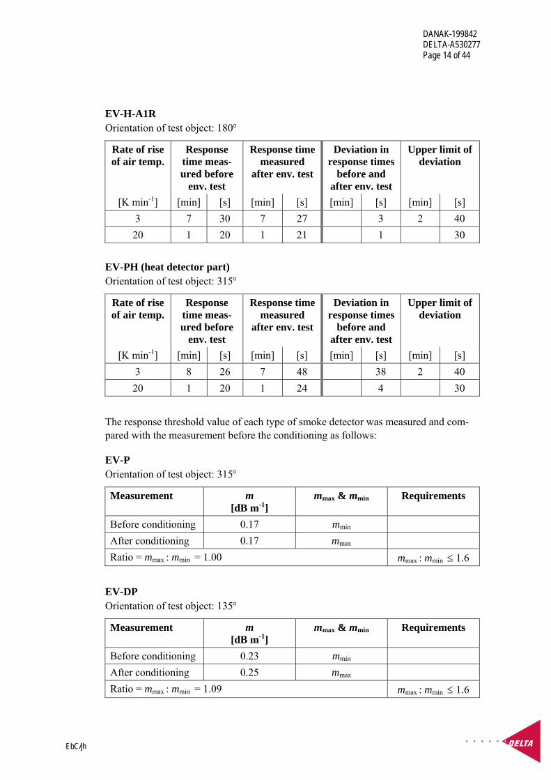
EV-H-A1R Orientation of test object: 180°
Rate of rise of air temp.
Response time meas-ured before
env. test
Response time measured
after env. test
Deviation in response times
before and after env. test
Upper limit of deviation
[K min-1] [min] [s] [min] [s] [min] [s] [min] [s] 3 7 30 7 27 3 2 40 20 1 20 1 21 1 30
EV-PH (heat detector part) Orientation of test object: 315°
Rate of rise of air temp.
Response time meas-ured before
env. test
Response time measured
after env. test
Deviation in response times
before and after env. test
Upper limit of deviation
[K min-1] [min] [s] [min] [s] [min] [s] [min] [s] 3 8 26 7 48 38 2 40 20 1 20 1 24 4 30
The response threshold value of each type of smoke detector was measured and com-pared with the measurement before the conditioning as follows:
EV-P Orientation of test object: 315°
Measurement m [dB m-1]
mmax & mmin Requirements
Before conditioning 0.17 mmin After conditioning 0.17 mmax Ratio = mmax : mmin = 1.00 mmax : mmin ≤ 1.6
EV-DP Orientation of test object: 135°
Measurement m [dB m-1]
mmax & mmin Requirements
Before conditioning 0.23 mmin After conditioning 0.25 mmax Ratio = mmax : mmin = 1.09 mmax : mmin ≤ 1.6

DANAK-199842 DELTA-A530277 Page 15 of 44
EbC/jh
EV-PH (smoke detector part) Orientation of test object: 270°
Measurement m [dB m-1]
mmax & mmin Requirements
Before conditioning 0.17 mmin After conditioning 0.17 mmax Ratio = mmax : mmin = 1.00 mmax : mmin ≤ 1.6
For all the heat detectors, the deviation between response time measured before and after the environmental test was below the upper limit as required.
The requirements for the ratio of mmax : mmin ≤1.6 for all the tested smoke detectors were fulfilled.
The detectors all passed the high voltage test without comments.

DANAK-199842 DELTA-A530277 Page 16 of 44
EbC/jh
3. Environmental tests This chapter describes the environmental tests. The tests are described with reference to test objects, specification and procedure.
3.1 Dry heat
Test objects
EV-H-A1R EV-H-CS EV-P EV-DP EV-PH.
Specification
IACS E10 Req. 1993/Rec.4, 2004, Test no. 5.
Procedure
IEC 60068-2-2 (1974), Test Bd: Dry heat for heat-dissipating object with gradual change of temperature, Amendment 1 (1993), Amendment 2 (1994).
Temperature : +70°C Duration : 2 hours Humidity : Below 50 %RH
One of each type of detector in its marine base is tested as specified in the standard.
The test objects are energised and monitored in quiescent condition during the condition-ing, except for the EV-H-A1R and EV-PH which are in heat alarm condition at this tem-perature, and it is monitored that they cannot be reset.
During the last hour of the conditioning, a simple functional test is performed. After re-covery, the simple functional test is repeated in standard environment.
The response times for each type of heat detector are measured after the conditioning and compared with the results achieved before the conditioning.
The response threshold value for each smoke detector is measured after the conditioning and compared with the results achieved before the conditioning.
Since the same EV-H-A1R detector and EV-PH detector was used for the three tests: dry heat, cold and damp heat, cyclic, carried out in this sequence, the intermediate functional test for these detectors was deleted. Only before and after the end of this sequence of tests, a functional test was carried out. Therefore, the measured response threshold

DANAK-199842 DELTA-A530277 Page 17 of 44
EbC/jh
levels/response times for these detectors are included in the test results of the dry heat test.
Results
Except as mentioned below, no malfunction was observed during the conditioning and the simple functional test was OK during the last hour of the conditioning period at the high temperature as well as after recovery.
At +70°C the EV-H-A1R and EV-PH were correctly in heat alarm condition and could not be reset.
The response time of each type of heat detector was measured and compared with the measurement before the conditioning as follows:
EV-H-A1R Orientation of test object: 180°
Rate of rise of air temp.
Response time meas-ured before
env. test
Response time measured
after env. test
Deviation in response times
before and after env. test
Upper limit of deviation
[K min-1] [min] [s] [min] [s] [min] [s] [min] [s] 3 7 35 7 41 6 2 40 20 1 22 1 19 3 30
EV-H-CS Orientation of test object: 180°
Rate of rise of air temp.
Response time meas-ured before
env. test
Response time measured
after env. test
Deviation in response times
before and after env. test
Upper limit of deviation
[K min-1] [min] [s] [min] [s] [min] [s] [min] [s] 3 10 25 10 36 11 2 40 20 1 53 1 54 1 30

DANAK-199842 DELTA-A530277 Page 18 of 44
EbC/jh
EV-PH (heat detector part) Orientation of test object: 315°
Rate of rise of air temp.
Response time meas-ured before
env. test
Response time measured
after env. test
Deviation in response times
before and after env. test
Upper limit of deviation
[K min-1] [min] [s] [min] [s] [min] [s] [min] [s] 3 9 10 8 32 38 2 40 20 1 45 1 39 6 30
The response threshold value of each type of smoke detector was measured and com-pared with the measurement before the conditioning as follows:
EV-P Orientation of test object: 315°
Measurement m [dB m-1]
mmax & mmin Requirements
Before conditioning 0.18 mmax After conditioning 0.17 mmin Ratio = mmax : mmin = 1.06 mmax : mmin ≤ 1.6
EV-DP Orientation of test object: 135°
Measurement m [dB m-1]
mmax & mmin Requirements
Before conditioning 0.23 mmax After conditioning 0.22 mmin Ratio = mmax : mmin = 1.05 mmax : mmin ≤ 1.6
EV-PH (smoke detector part) Orientation of test object: 270°
Measurement m [dB m-1]
mmax & mmin Requirements
Before conditioning 0.20 mmax After conditioning 0.16 mmin Ratio = mmax : mmin = 1.25 mmax : mmin ≤ 1.6

DANAK-199842 DELTA-A530277 Page 19 of 44
EbC/jh
For all the heat detectors, the deviation between response time measured before and after the environmental test was below the upper limit as required.
The requirements for the ratio of mmax : mmin ≤1.6 for all the tested smoke detectors were fulfilled.
The detectors all passed the dry heat test, but with the comments given below.
Comments
The dry heat test revealed that the built-in LED of the detector type EV-H-A1R did not light up when in alarm condition. Otherwise, it functioned correctly in all other aspects, and the alarm signal was correctly received by the CS4000 control panel.
A subsequent failure analysis made by Nittan showed that the fault was caused by a bad soldering. The detector was repaired and sent back to DELTA for inspection and found to be functioning correctly.
Please see information regarding the fault in Chapter 4.
3.2 Damp heat, cyclic
Test objects
EV-H-A1R EV-H-CS EV-P EV-DP EV-PH.
Specification
IACS E10: Req. 1993/Rec.4, 2004, 1997, Test no. 6.

DANAK-199842 DELTA-A530277 Page 20 of 44
EbC/jh
Procedure
IEC 60068-2-30 (1980), Test Db: Damp heat cyclic (12 + 12 hours' cycle), Variant 1, Amendment 1 (1985).
Lower temperature : 25°C Humidity at lower temperature : >95 %RH
Upper temperature : 55°C Humidity at upper temperature : 93 %RH Number of cycles : 2
One of each type of detector in its marine base is tested as specified in the standard.
The test objects are energised and in quiescent condition during the first cycle. A simple functional test is performed during the first 2 hours of the 55°C phase.
During the rise of temperature to the high temperature, condensation on the test objects is ensured.
During the second cycle, the test objects are deenergised. However, once within the last 2 hours of the second 55°C phase, the test objects are energised temporarily for a simple functional test to be performed.
After recovery, a simple functional test is carried out.
The insulation resistance is measured after the high voltage test and compared with the initial measurements of the insulation resistance as described in Section 2.1.
The response times for each type of heat detector are measured after the conditioning and compared with the results achieved before the conditioning.
The response threshold value for each smoke detector is measured after the conditioning and compared with the results achieved before the conditioning.
Since the same EV-H-A1R detector and EV-PH detector were used for the three tests: dry heat, cold and damp heat, cyclic, carried out in a sequence, the intermediate func-tional test for these detectors was deleted. Only before and after the end of this sequence of tests, a functional test was carried out. Therefore, the measured response threshold levels /response times for these detectors is included in the test results of the dry heat test in Section 3.1.
Similarly, the same EV-P detector and EV-DP detector were used for the two tests: cold and damp heat, cyclic, carried out in a sequence, the intermediate functional test was de-leted. Only before and after the end of these tests, a functional test was carried out. Therefore, the measured response threshold levels/response times for these detectors is included in the test results of the cold test in Section 3.4.

DANAK-199842 DELTA-A530277 Page 21 of 44
EbC/jh
Results
Except as mentioned below, no malfunction was observed during the conditioning, and the simple function of the test objects was OK during the first and second cycle at 55°C, 93 %RH and after recovery. No corrosion attack was observed after the conditioning.
The insulation resistance measured was within the required limits. Please see results in Section 2.1.
The response time of each type of heat detector was measured and compared with the measurement before the conditioning.
The results for the detectors type EV-H-A1R and EV-PH are included in the test results of the dry heat test in Section 3.1.
The response time for the heat detector type EV-H-CS was measured and compared with the measurement before the conditioning as follows:
EV-H-CS Orientation of test object: 180°
Rate of rise of air temp.
Response time meas-ured before
env. test
Response time measured
after env. test
Deviation in response times
before and after env. test
Upper limit of deviation
[K min-1] [min] [s] [min] [s] [min] [s] [min] [s] 3 12 29 12 31 2 2 40 20 2 35 2 44 9 30
The response threshold value of each type of smoke detectors was measured and com-pared with the measurement before the conditioning.
The results for the detector type EV-PH are included in the test results of the dry heat test in Section 3.1.
The results for the detectors type EV-P and EV-DP are included in the test results of the cold test in Section 3.4.
For all the heat detectors, the deviation between response time measured before and after the environmental test was below the upper limit as required.
The requirements for the ratio of mmax : mmin ≤1.6 for all the tested smoke detectors were fulfilled.
The detectors all passed the damp heat, cyclic test, but with the comments given below.
DANAK-199842 DELTA-A530277 Page 22 of 44
EbC/jh
Comments
The damp heat test revealed that the built-in LED of the detector type EV-H-A1R did not light up when in alarm condition. Otherwise, it functioned correctly in all other as-pects, and the alarm signal was correctly received by the CS4000 control panel.
A subsequent failure analysis made by Nittan showed that the fault was caused by a bad soldering. The detector was repaired and sent back to DELTA for inspection and found to be functioning correctly.
Also, the damp heat test revealed that when switching on at the second simple functional test during the exposure, the EV-PH gave the indication SENSOR FAULT (129) on the control panel.
The fault could not be reset before heat and smoke alarms had been subsequently pro-voked.
A new detector type EV-PH from an improved controlled production was tested at DELTA in a second damp heat, cyclic test, including initial and final response parame-ters, insulation resistance and simple function check. The new detector passed the damp heat, cyclic test without comments.
Please see information regarding the fault in Chapter 4.
3.3 Vibration
Test objects
EV-H-A1R EV-P EV-DP EV-PH.
Specification
IACS E10 Req. 1993/Rec.4, 2004, Test no. 7.
Procedure
IEC 60068-2-6 (1985), Test Fc: Vibration (sinusoidal).
Response investigation (test objects switched off) followed by endurance by frequency dwelling (switched on) is carried out in each of three axes using the following parame-ters:
DANAK-199842 DELTA-A530277 Page 23 of 44
EbC/jh
Frequency range : 2 - 100 Hz Frequency/amplitude : 2 - 25 Hz : ±1.6 mm 25-100 Hz : ±4 g Sweep rate : Max. 1 octave/min. Number of axes : 3 mutually perpendicular
One of each type of detector in its marine base is tested as specified in the standard, ex-cept for the EV-H-CS detector, which was not included in this test. With respect to this test, it is similar to EV-H-A1R, as described in Section 1.1, Introduction
During the response investigation, resonance frequencies are determined by means of stroboscopic light with slow-motion facility and accelerometer measurements of the am-plification factors (Q). Resonance frequencies with Q≥ 2 are recorded.
Endurance by frequency dwelling is carried out for 90 minutes at each resonance fre-quency with a Q≥ 2, or 90 minutes at 30 Hz if no such resonances are found.
A simple functional test and visual inspection is performed after the conditioning.
Results
No resonance frequencies with an amplification factor above 2 were recorded for any of the tested detectors.
No damage or malfunction was observed during or after the exposures and the simple function test was OK after the test.
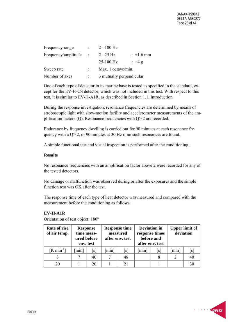
The response time of each type of heat detector was measured and compared with the measurement before the conditioning as follows:
EV-H-A1R Orientation of test object: 180°
Rate of rise of air temp.
Response time meas-ured before
env. test
Response time measured
after env. test
Deviation in response times
before and after env. test
Upper limit of deviation
[K min-1] [min] [s] [min] [s] [min] [s] [min] [s] 3 7 40 7 48 8 2 40 20 1 20 1 21 1 30

DANAK-199842 DELTA-A530277 Page 24 of 44
EbC/jh
EV-PH (heat detector part) Orientation of test object: 315°
Rate of rise of air temp.
Response time meas-ured before
env. test
Response time measured
after env. test
Deviation in response times
before and after env. test
Upper limit of deviation
[K min-1] [min]
[s] [min] [s] [min] [s] [min]
[s]
3 7 43 8 35 52 2 40 20 1 23 1 26 3 30
The response threshold value of each type of smoke detector was measured and com-pared with the measurement before the conditioning as follows:
EV-P Orientation of test object: 315°
Measurement m [dB m-1]
mmax & mmin Requirements
Before conditioning 0.19 mmax After conditioning 0.16 mmin Ratio = mmax : mmin = 1.19 mmax : mmin ≤ 1.6
EV-DP Orientation of test object: 135°
Measurement m [dB m-1]
mmax & mmin Requirements
Before conditioning 0.25 mmin After conditioning 0.25 mmax Ratio = mmax : mmin = 1.00 mmax : mmin ≤ 1.6
EV-PH (smoke detector part) Orientation of test object: 270°
Measurement m [dB m-1]
mmax & mmin Requirements
Before conditioning 0.18 mmin After conditioning 0.18 mmax Ratio = mmax : mmin = 1.00 mmax : mmin ≤ 1.6
For all the heat detectors, the deviation between response time measured before and after the environmental test was below the upper limit as required.

DANAK-199842 DELTA-A530277 Page 25 of 44
EbC/jh
The requirements for the ratio of mmax : mmin ≤1.6 for all the tested smoke detectors were fulfilled.
The detectors all passed the vibration test without comments.
3.4 Cold
Test objects
EV-H-A1R EV-P EV-DP EV-PH.
Specification
IACS E10: Req. 1993/Rec.4, 2004, Test no. 11.
Procedure
IEC 60068-2-1 (1990), Test Ad: Cold for heat-dissipating object with gradual change of temperature, Amendment 1 (1993), Amendment 2 (1994).
Temperature : -25°C Duration : 2 hours
One of each type of detector in its marine base is tested as specified in the standard, ex-cept for the EV-H-CS detector, which was not included in this test. With respect to this test, it is similar to EV-H-A1R, as described in Section 1.1, Introduction
The test objects are deenergised during the conditioning. However, during the last hour of the conditioning at the low temperature, the test objects are energised and a simple functional test is performed. After recovery, a simple functional test is carried out.
The insulation resistance is measured after the high voltage test and compared with the initial measurements of the insulation resistance as described in Section 2.1.
The response times for each type of heat detector are measured after the conditioning and compared with the results achieved before the conditioning.
The response threshold value for each smoke detector is measured after the conditioning and compared with the results achieved before the conditioning.
Since the same EV-H-A1R detector and EV-PH detector were used for the three tests: dry heat, cold and damp heat, cyclic, carried out in a sequence, the intermediate func-tional test for these detectors was deleted. Only before and after the end of this sequence of tests, a functional test was carried out. Therefore, the measured response threshold

DANAK-199842 DELTA-A530277 Page 26 of 44
EbC/jh
levels /response times for these detectors is included in the test results of the dry heat test in Section 3.1.
Similarly, the same EV-P detector and EV-DP detector were used for the two tests: cold and damp heat, cyclic, carried out in a sequence, the intermediate functional test was de-leted. Only before and after the end of these tests, a functional test was carried out. Therefore, the measured response threshold levels/response times for these detectors is included in the test results of the cold test in Section 3.4.
Results
No malfunction was observed when energising the test objects, and the simple functional test was OK during the last hour of the conditioning period at the low temperature and after recovery. (It is noted that the same detector type EV-H-A1R as tested during the previous dry heat test now functioned correctly with its LED lighting up in alarm condi-tion, both during and after this exposure.)
The insulation resistance measured was within the required limits. Please see results in Section 2.1.
The response time of each type of heat detector was measured and compared with the measurement before the conditioning.
The results for the detectors type EV-H-A1R and EV-PH are included in the test results of the dry heat test in Section 3.1.
The response threshold value of each type of smoke detectors was measured and com-pared with the measurement before the conditioning.
The results for the detector type EV-PH is included in the test results of the dry heat test in Section 3.1.
EV-P Orientation of test object: 315°
Measurement m [dB m-1]
mmax & mmin Requirements
Before conditioning 0.16 mmin After conditioning 0.17 mmax Ratio = mmax : mmin = 1.06 mmax : mmin ≤ 1.6

DANAK-199842 DELTA-A530277 Page 27 of 44
EbC/jh
EV-DP Orientation of test object: 135°
Measurement m [dB m-1]
mmax & mmin Requirements
Before conditioning 0.19 mmin After conditioning 0.22 mmax Ratio = mmax : mmin = 1.16 mmax : mmin ≤ 1.6
For all the heat detectors, the deviation between response time measured before and after the environmental tests was below the upper limit as required.
The requirements for the ratio of mmax : mmin ≤1.6 for all the tested smoke detectors were fulfilled.
The detectors all passed the cold test without comments.
3.5 Salt mist
Test objects
EV-H-A1R EV-P EV-DP EV-PH.
Specification
IACS E10 Req. 1993/Rec.4, 2004, Test no. 12.
Procedure
IEC 60068-2-52 (1996-02), Test Kb: Salt mist, cyclic (sodium, chloride solution)
Severity 1:
Salt solution (spray) : 5% NaCl Spray duration : 2 hours Humidity storage : 40°C and 93%RH Storage period : 7 days Number of cycles : 4 (total of 28 days)
One of each type of detector in its marine base is tested as specified in the standard, ex-cept for the EV-H-CS detector, which was not included in this test. With respect to this test, it is similar to EV-H-A1R, as described in Section 1.1, Introduction

DANAK-199842 DELTA-A530277 Page 28 of 44
EbC/jh
The test objects are deenergised during the conditioning. After recovery, a simple func-tional test is carried out.
The insulation resistance is measured after the high voltage test and compared with the initial measurements of the insulation resistance as described in Section 2.1.
A visual inspection of the test objects were carried out after the conditioning.
Results
No corrosion was observed after the conditioning and the simple functional test was OK after recovery.
The insulation resistance measured was within the required limits. Please see results in Section 2.1.
No corrosion attack was observed after the conditioning.
The response time of each type of heat detector was measured and compared with the measurement before the conditioning as follows:
EV-H-A1R Orientation of test object: 180°
Rate of rise of air temp.
Response time meas-ured before
env. test
Response time measured
after env. test
Deviation in response times
before and after env. test
Upper limit of deviation
[K min-1] [min] [s] [min] [s] [min] [s] [min] [s] 3 7 50 7 48 2 2 40 20 1 23 1 24 1 30
EV-PH (heat detector part) Orientation of test object: 315°
Rate of rise of air temp.
Response time meas-ured before
env. test
Response time measured
after env. test
Deviation in response times
before and after env. test
Upper limit of deviation
[K min-1] [min] [s] [min] [s] [min] [s] [min] [s] 3 8 32 8 25 7 2 40 20 1 31 1 28 3 30
The response threshold value of each type of smoke detector was measured and com-pared with the measurement before the conditioning as follows:

DANAK-199842 DELTA-A530277 Page 29 of 44
EbC/jh
EV-P Orientation of test object: 315°
Measurement m [dB m-1]
mmax & mmin Requirements
Before conditioning 0.18 mmax After conditioning 0.17 mmin Ratio = mmax : mmin = 1.06 mmax : mmin ≤ 1.6
EV-DP Orientation of test object: 135°
Measurement m [dB m-1]
mmax & mmin Requirements
Before conditioning 0.24 mmax After conditioning 0.23 mmin Ratio = mmax : mmin = 1.04 mmax : mmin ≤ 1.6
EV-PH (smoke detector part) Orientation of test object: 270°
Measurement m [dB m-1]
mmax & mmin Requirements
Before conditioning 0.20 mmax After conditioning 0.19 mmin Ratio = mmax : mmin = 1.05 mmax : mmin ≤ 1.6
For all the heat detectors, the deviation between response time measured before and after the environmental test was below the upper limit as required.
The requirements for the ratio of mmax : mmin ≤1.6 for all the tested smoke detectors were fulfilled.
The detectors all passed the salt mist test without comments.
3.6 Radiated emission
Test objects
EV-H-A1R EV-P EV-DP EV-PH.
DANAK-199842 DELTA-A530277 Page 30 of 44
EbC/jh
Specification
IACS E10: Req. 1993/Rec.4, 2004, Test no. 19 (bridge and deck zone).
Procedure
CISPR 16-1 (1999-10), Specification for radio disturbance and immunity measuring ap-paratus and methods - Part 1: Radio disturbance and immunity measuring apparatus.
CISPR 16-2:2002, Specification for radio disturbance and immunity measuring appara-tus and methods - Part 2: Methods of measurement of disturbances and immunity.
Frequency range : 0.15 - 2000 MHz
Limits (quasi-peak) : 0.15 - 0.30 MHz : 80 - 52 dBμV/m
0.30 - 30 MHz : 52 - 34 dBμV/m
30 - 2000 MHz : 54 dBμV/m, except for 156 - 165 MHz : 24 dBμV/m Photo of test set-up : See annex 3
One of each type of detector in its marine base is tested as specified in the standard, ex-cept for the EV-H-CS detector, which was not included in this test. With respect to this test, it is similar to EV-H-A1R, as described in Section 1.1, Introduction
The electric field is measured with antennas at a distance of 3 m.
The test objects are energised and in quiescent condition during the measurement.
Results
The measured emission from 0.15 to 2000 MHz was below the limits for all the test ob-jects.
The detectors all passed the salt mist test without comments.
DANAK-199842 DELTA-A530277 Page 31 of 44
EbC/jh
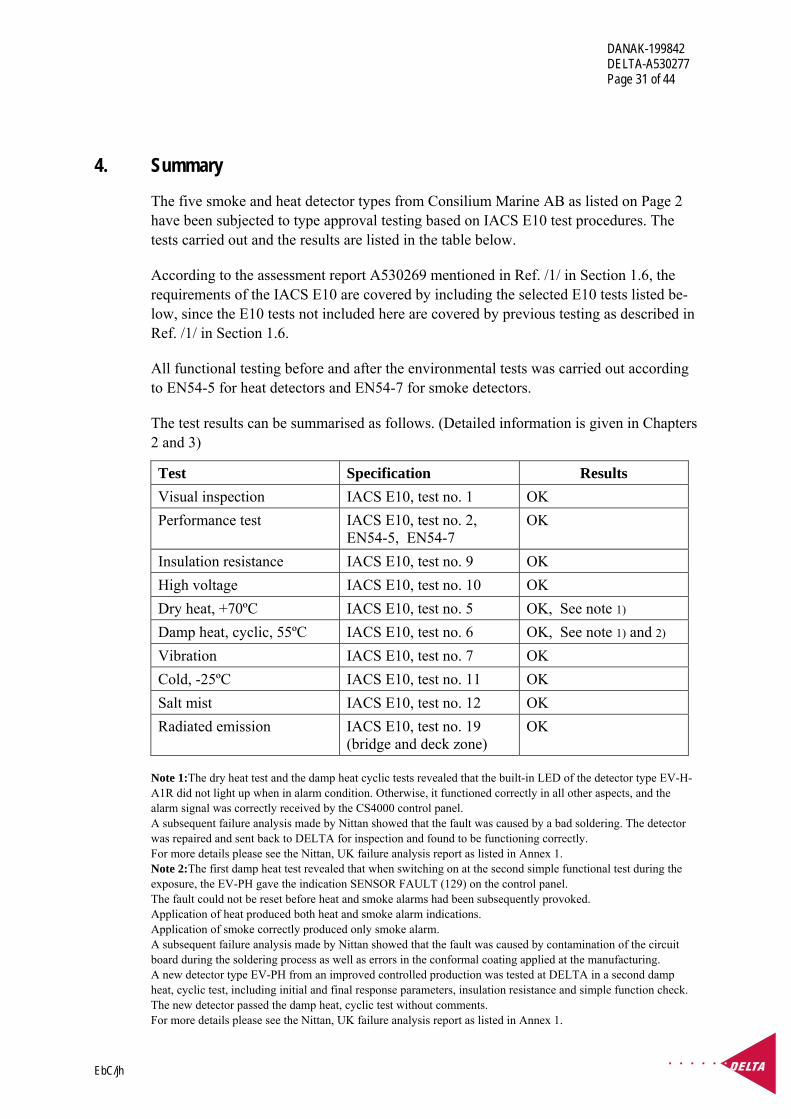
4. Summary The five smoke and heat detector types from Consilium Marine AB as listed on Page 2 have been subjected to type approval testing based on IACS E10 test procedures. The tests carried out and the results are listed in the table below.
According to the assessment report A530269 mentioned in Ref. /1/ in Section 1.6, the requirements of the IACS E10 are covered by including the selected E10 tests listed be-low, since the E10 tests not included here are covered by previous testing as described in Ref. /1/ in Section 1.6.
All functional testing before and after the environmental tests was carried out according to EN54-5 for heat detectors and EN54-7 for smoke detectors.
The test results can be summarised as follows. (Detailed information is given in Chapters 2 and 3)
Test Specification Results Visual inspection IACS E10, test no. 1 OK Performance test IACS E10, test no. 2,
EN54-5, EN54-7 OK
Insulation resistance IACS E10, test no. 9 OK High voltage IACS E10, test no. 10 OK Dry heat, +70ºC IACS E10, test no. 5 OK, See note 1) Damp heat, cyclic, 55ºC IACS E10, test no. 6 OK, See note 1) and 2) Vibration IACS E10, test no. 7 OK Cold, -25ºC IACS E10, test no. 11 OK Salt mist IACS E10, test no. 12 OK Radiated emission IACS E10, test no. 19
(bridge and deck zone) OK
Note 1:The dry heat test and the damp heat cyclic tests revealed that the built-in LED of the detector type EV-H-A1R did not light up when in alarm condition. Otherwise, it functioned correctly in all other aspects, and the alarm signal was correctly received by the CS4000 control panel. A subsequent failure analysis made by Nittan showed that the fault was caused by a bad soldering. The detector was repaired and sent back to DELTA for inspection and found to be functioning correctly. For more details please see the Nittan, UK failure analysis report as listed in Annex 1. Note 2:The first damp heat test revealed that when switching on at the second simple functional test during the exposure, the EV-PH gave the indication SENSOR FAULT (129) on the control panel. The fault could not be reset before heat and smoke alarms had been subsequently provoked. Application of heat produced both heat and smoke alarm indications. Application of smoke correctly produced only smoke alarm. A subsequent failure analysis made by Nittan showed that the fault was caused by contamination of the circuit board during the soldering process as well as errors in the conformal coating applied at the manufacturing. A new detector type EV-PH from an improved controlled production was tested at DELTA in a second damp heat, cyclic test, including initial and final response parameters, insulation resistance and simple function check. The new detector passed the damp heat, cyclic test without comments. For more details please see the Nittan, UK failure analysis report as listed in Annex 1.

DANAK-199842 DELTA-A530277 Page 32 of 44
EbC/jh
Annex 1
Documentation for the test objects

DANAK-199842 DELTA-A530277 Page 33 of 44
EbC/jh
Documentation for the test objects
Type Title Number Version Date Pages
Data sheet Heat detector Sal-wico EV-H 54°C
40000.EV-H 54C.06.1.E
- - 1
Data sheet Heat detector Sal-wico EV-H 84°C
40005.EV-H 84C.06.1.E
- - 1
Diagram EV-H - - 010309 1
Parts list PCB Assembly Part List EV-H
- Rev 2 28/01/03 3
Certificate of product confor-mity
EV-H-A1R and EV-H-CS Heat Detectors
041h - 12 May 2003
2
Layout drawing EV-PH/EV-H PCB Silkscreen (Top)
100003 1 13/12/02 1
Data sheet Optical smoke detec-tor Salwico EV-P
40020EV.P.06.1.E - - 1
Diagram EV-P Circuit 100000 0.06 030131 1
Parts list PCB Assembly Part lList EV-P
- Rev 2 28/01/03 3
Layout drawing EV-P PCB Silk-screen
100001 1 13/12/02 1
Certificate of product confor-mity
EV-P and EV-DP Optical Smoke De-tectors
041f - 12 May 2003
2
Data sheet Combined optical smoke/heat Detector Salwico EV-PH
40030.EV-PH.06.1.E
- - 1
Diagram EV-PH Circuit - - 030130 1
Parts list PCB Assembly Part List EV-PH
- Rev2 28/01/03 4
Layout drawing EV-PH/EV-H 100003 1 13/12/02 1
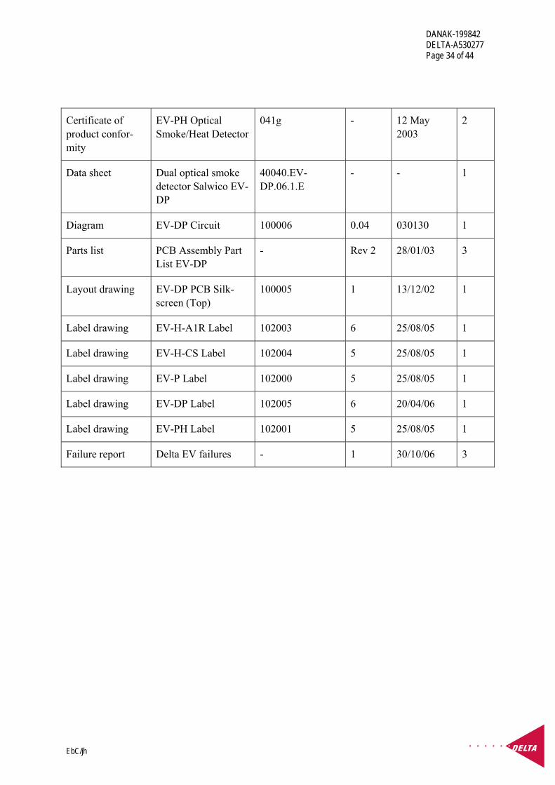
DANAK-199842 DELTA-A530277 Page 34 of 44
EbC/jh
Certificate of product confor-mity
EV-PH Optical Smoke/Heat Detector
041g - 12 May 2003
2
Data sheet Dual optical smoke detector Salwico EV-DP
40040.EV-DP.06.1.E
- - 1
Diagram EV-DP Circuit 100006 0.04 030130 1
Parts list PCB Assembly Part List EV-DP
- Rev 2 28/01/03 3
Layout drawing EV-DP PCB Silk-screen (Top)
100005 1 13/12/02 1
Label drawing EV-H-A1R Label 102003 6 25/08/05 1
Label drawing EV-H-CS Label 102004 5 25/08/05 1
Label drawing EV-P Label 102000 5 25/08/05 1
Label drawing EV-DP Label 102005 6 20/04/06 1
Label drawing EV-PH Label 102001 5 25/08/05 1
Failure report Delta EV failures - 1 30/10/06 3

DANAK-199842 DELTA-A530277 Page 35 of 44
EbC/jh
Photos of test objects
Each type of test object is shown in its normal appearance.
3.1 EV-H-A1R Heat detector, class A1R
3.2 EV-H-CS Heat detector, class CS
3.3 EV-P Smoke detector
3.4 EV-DP Double optical smoke detector
3.5 EV-PH Optical smoke/heat detector, class A1R

DANAK-199842 DELTA-A530277 Page 36 of 44
EbC/jh
Annex 2
Documentation for the test set-up

DANAK-199842 DELTA-A530277 Page 37 of 44
EbC/jh

DANAK-199842 DELTA-A530277 Page 38 of 44
EbC/jh
Annex 3
Test set-up and test record sheets regarding radiated emission

DANAK-199842 DELTA-A530277 Page 39 of 44
EbC/jh
Test set-up for measurements of radiated emission 0.15 - 30 MHz.
Test set-up for measurements of radiated emission 30-1000 GHz.

DANAK-199842 DELTA-A530277 Page 40 of 44
EbC/jh
Test set-up for measurements of radiated emission 1-2 GHz.

DANAK-199842 DELTA-A530277 Page 41 of 44
EbC/jh
DELTA Electronics Testing, EMC Section EUT: Salwico: EV-HA1R, EV-P, EV-DP and EV-PH Manufacturer: Consilium Marine AB Operating Condition: Ant 1 m Vertical. Test Site: EMC-5 Operator: CMT - A530277 Test Specification: IACS E10:2004 Comment: Sheet 1 Start of Test: 2006-09-08
0
10
20
30
40
50
60
Level [dBµV/m]
30M 50M 70M 100M 200M 300M 500M 700M 1GFrequency [Hz]
xxx
x
xx
x MES Maximering_fin QP MES IEC945 1m 30 MaxPk 1 LIM RE, E10, QP Radiated Emission
MEASUREMENT RESULT: "Maximering_fin QP" 2006-09-08 12:20 Frequency Level Transd Limit Margin Height Azimuth Polarisation MHz dBµV/m dB dBµV/m dB cm deg 37.000000 18.20 16.8 54.0 35.8 111.0 95.00 VERTICAL 43.530000 14.70 13.1 54.0 39.3 112.0 148.00 VERTICAL 45.310000 16.10 12.1 54.0 37.9 112.0 191.00 VERTICAL 80.000000 9.60 10.0 54.0 44.4 157.0 73.00 VERTICAL 98.600000 16.30 12.4 54.0 37.7 111.0 121.00 VERTICAL 158.425000 12.90 13.0 24.0 11.1 219.0 299.00 VERTICAL

DANAK-199842 DELTA-A530277 Page 42 of 44
EbC/jh
DELTA Electronics Testing, EMC Section EUT: Salwico: EV-HA1R, EV-P, EV-DP and EV-PH Manufacturer: Consilium Marine AB Operating Condition: Ant 4 m horizontal Test Site: EMC-5 Operator: CMT - A530277 Test Specification: IACS E10:2004 Comment: Sheet 2 Start of Test: 2006-09-08
0
10
20
30
40
50
60
Level [dBµV/m]
30M 50M 70M 100M 200M 300M 500M 1G 2GFrequency [Hz]
xxx
x
xx
x MES Maximering_fin QP MES IEC945 4m 30 MaxPk 1 LIM RE, IEC 60945 Radiated Emission

DANAK-199842 DELTA-A530277 Page 43 of 44
EbC/jh
DELTA Electronics Testing, EMC Section EUT: Salwico: EV-HA1R, EV-P, EV-DP and EV-PH Manufacturer: Consilium Marine AB Operating Condition: Ant. 0 deg. Test Site: EMC-5 Operator: CMT - A530277 Test Specification: IACS E10:2004 Comment: Sheet 3 Start of Test: 2006-09-08
0
20
40
60
80
100
Level [dBµV/m]
150k 300k 500k 1M 2M 3M 5M 7M 10M 30MFrequency [Hz]
x
x MES mfield_0001_fin QP MES ME IEC 945 (0 MaxPk LIM ME, E10, QP Magnetic Emission
MEASUREMENT RESULT: "mfield_0001_fin QP" 2006-09-08 12:51 Frequency Level Transd Limit Margin Azimuth MHz dBµV/m dB dBµV/m dB deg 0.265000 38.40 19.4 55.4 17.0 114.00

DANAK-199842 DELTA-A530277 Page 44 of 44
EbC/jh
DELTA Electronics Testing, EMC Section EUT: Salwico: EV-HA1R, EV-P, EV-DP and EV-PH Manufacturer: Consilium Marine AB Operating Condition: Ant. 90 deg. Test Site: EMC-5 Operator: CMT - A530277 Test Specification: IACS E10:2004 Comment: Sheet 4 Start of Test: 2006-09-08
0
20
40
60
80
100
Level [dBµV/m]
150k 300k 500k 1M 2M 3M 5M 7M 10M 30MFrequency [Hz]
x
x MES mfield_0001_fin QP MES ME IEC 945 (90 MaxPk LIM ME, E10, QP Magnetic Emission
MEASUREMENT RESULT: "mfield_0001_fin QP" 2006-09-08 13:06 Frequency Level Transd Limit Margin Azimuth MHz dBµV/m dB dBµV/m dB deg 0.265000 37.50 19.4 55.4 17.8 41.00